Embed Size (px)
Citation preview
Final report
25 June 2015 Page
24-6-2015
Automation of pressure vessel winding | The Hague University of Applied Sciences
SMR2 FINAL REPORT Lightweight Structures BV Filament Winder

Final report
25 June 2015 Page i
FINAL REPORT
Lightweight Structures BV Filament Winder
Client Maarten Labordus
Place Delft, Haagse Hogeschool
Date 24-6-2015
Version 1.0
Tutors Frederick de Wit
Thijs Brilleman
Project members Marc Cornet
Justin Gross
Sjors van Leeuwen
Rick den Ouden
Martijn van Paassen
Gerben Taanman
Dirk van Trigt
Jens Vertongen

Final report
25 June 2015 Page ii
Preface This final report has been written for both the Vessel wrapper project delivered by the Lightweight
Structures and the minor Smart Manufacturing and Robotics presented by the Academy of the TIS Delft.
First off we would like to thank Lightweight Structures for the project assignment and their help during
the project. We would also like to thank mr. T. Brilleman and mr. F. de Wit for their guidance during this
project.
Final report
25 June 2015 Page iii
Summary For Lightweight Structures BV the existing setup to wind tape around a plastic pressure vessel was
improved. The goals were to redesign the EOAT and determine its capabilities; to optimizing the
manipulator control system; make rotation speed of the pressure vessel variable and controllable; and to
build a prototype winding program for the robot.
The pressure vessel manipulator was improved upon in several areas. Bearings were replaced, a new
driveshaft was made and mouting accessories to secure the pressure vessel in the manipulator were
designed and 3d-printed. The motor was replaced by a M56b4, a 0,09 kW motor from Carpanelli. The
motor is mounted on the frame with a reaction compensation connection. Two reductions, a single gear
and a worm reduction, were placed after the motor resulting in a total reduction of 1083 with an
efficiency of 45%. Combined with the E2-201-H1F frequency converter the pressure vessel can now be
rotated with a speed from 0.5 to 1.5 rpm.
To heat the tape a new heating element and aluminum casing was provided by Lightweight Structures BV.
This casing is replaced by a newly created aluminum casing. A new EOAT was developed to mount this
heating element and casing on the robot while also providing isolation around the heating element and
aluminum casing to improve the efficiency. To achieve this a new mounting mechanism was designed. The
outer casing is made out of AlMg3 to prevent oxidation. This casing consists of two parts, a top and a
bottom part, and provides spacing - 2 cm or more - between the heating element and the outer casing.
The space is filled with the insulation material Super Isol. To measure the temperature of the tape exiting
the EOAT an IR-Sensor was mounted on the EOAT. The tape temperature is measured by the MLX90614
from Melexis and read via I2C with an Arduino.
To wind the desired pattern with the tape both the EOAT position and the vessel rotation have to be
controlled. First the path over the vessel was determined. This was done using the CAD-model of the
vessel and the cross section between this vessel and 3 projected planes. One plane for the middle of the
vessel under the desired 25 degree angle and two planes for the rounded ends of the vessel. Points on
these cross-sections, spaced 1,2 cm apart, form the path perpendicular over the vessel. Using the
calculation of the rotation angles the relation of the vessel rotation and the EOAT movement was
determined. A robot program was made to move the EOAT in this desired pattern while also controlling
the vessel speed.

Final report
25 June 2015 Page iv
List of figures Figure 1: Example of wrapped pressure vessel ............................................................................................... 1
Figure 2: Current design .................................................................................................................................. 3
Figure 3: The vessel manipulator .................................................................................................................... 5
Figure 4: Frame analysis .................................................................................................................................. 6
Figure 5: Bottom adapter(left)/ Top adapter (right) ....................................................................................... 7
Figure 6: Final manipulator overview .............................................................................................................. 9
Figure 7: Final manipulator, front view ......................................................................................................... 10
Figure 8: The EOAT design of the previous project group ............................................................................ 12
Figure 9: Redesign aluminium casing ............................................................................................................ 13
Figure 10: First design ................................................................................................................................... 13
Figure 11: First design before test ................................................................................................................. 14
Figure 12: First design after test.................................................................................................................... 14
Figure 13: Final design consisting of casing and cover .................................................................................. 16
Figure 14: Casing and cover assembled with heating element and robot mount ........................................ 16
Figure 15: Assembly casing and cover ........................................................................................................... 16
Figure 16: Line for applying tape to pressure vessel ..................................................................................... 19
Figure 17: Projected assumpted geodesic curve ........................................................................................... 20
Figure 18: Created path across the surface of the pressure vessel CAD model ........................................... 20
Figure 19: Cross Section determine angle related to applying tape ............................................................. 21
Figure 20: Relation rotation PVM and movement EOAT .............................................................................. 21
Figure 21: Movement EOAT and rotation PVM related to time ................................................................... 22
Figure 22: cross-section of the vessel shown multiple variables used in the robot code ............................. 23
Figure 23: Final Inventor design .................................................................................................................... 27
Figure 24: The vessel manipulator ................................................................................................................ 28
Figure 25: Pneumatic scheme of the pneumatic system .............................................................................. 30
Figure 26: Electrical scheme .......................................................................................................................... 32
Figure 27: Frequency display ......................................................................................................................... 33
Figure 28: Render image of the vessel manipulator at the beginning .......................................................... 35
Figure 29: AC motor ...................................................................................................................................... 38
Figure 30: DC motor ...................................................................................................................................... 38
Final report
25 June 2015 Page v
Figure 31: Servo motor .................................................................................................................................. 38
Figure 32: Gear reduction ............................................................................................................................. 39
Figure 33: Worm gear reduction ................................................................................................................... 39
Figure 34: Belt reduction ............................................................................................................................... 39
Figure 35: Chain reduction ............................................................................................................................ 39
Figure 36: Epicyclic gear reduction ................................................................................................................ 40
Figure 37: Encoder ........................................................................................................................................ 41
Figure 38: Frequency converter .................................................................................................................... 42
Figure 39: Schematic rod forces .................................................................................................................... 47
Figure 40: Electric scheme current situation ................................................................................................. 49
Figure 41: Frequency converter screen lay-out ............................................................................................ 50
Figure 42: Electric scheme new situation ...................................................................................................... 51
Figure 43: Driveshaft drawing ....................................................................................................................... 57
Figure 44: Final bearings ............................................................................................................................... 58
Figure 45: Final motor ................................................................................................................................... 58
Figure 46: Final motor with reduction .......................................................................................................... 59
Figure 47:The EOAT design of the previous project group ........................................................................... 65
Figure 48: Aluminium Casing heating element ............................................................................................. 66
Figure 49: First redesign ................................................................................................................................ 66
Figure 50: First design before test ................................................................................................................. 67
Figure 51: First design after test.................................................................................................................... 67
Figure 52: Redesign outer casing assembled with heating element and robot mount ................................ 68
Figure 53: Redesign outer casing in parts ..................................................................................................... 68
Figure 54: Redesign outer casing assembled ................................................................................................ 68
Figure 55: Final EOAT-1,2 .............................................................................................................................. 70
Figure 56: Final EOAT-3 ................................................................................................................................. 71
Figure 57: Test setup ..................................................................................................................................... 75
Figure 58: Scorched glass wool ..................................................................................................................... 77
Figure 59: Glass fibre sticking to the EOAT ................................................................................................... 78
Figure 60: Placing ring to hold the container in place above the sensor ...................................................... 87
Figure 61: A plastic container with ice water above the sensor .................................................................. 87
Figure 62: Holding a realistically sized object above the sensor ................................................................... 89

Final report
25 June 2015 Page vi
Figure 63: Comparing the Melexis sensor with the Testo IR sensor ............................................................. 91
Figure 64: The first test at 11mm distance comparing the MLX90614 vs de Testo ...................................... 91
Figure 65: The second test to confirm our results ........................................................................................ 92
Figure 66: Increasing the distance makes the sensor unusable .................................................................... 92
Figure 67: Comparing the MLX90614 with the Testo at higher temperatures and a shorter distance ........ 93
Final report
25 June 2015 Page vii
List of tables Table 1: Festo components 31
Table 2: Trade-off motor 38
Table 3: Trade-off reduction 40
Table 4: Trade-off encoder 41
Table 5: Trade-off control 42
Table 6: Morphologic chart 43
Table 7: Magnitudes and units 44
Table 8: Motor poles 45
Table 9: Frequency converter functions 52
Table 10: Relation frequency, motor speed and input voltage 54
Table 11: Test results of the input voltage for each frequency step 55
Table 12: IR-sensor choices 85
Table 13: First measurements 88
Table 14: Measurements where sensor reading stabilize 88
Table 15: Measurements of a smaller object held in boiling water before measuring 89
Final report
25 June 2015 Page viii
Table of content Preface............................................................................................................................................................. ii
Summary ........................................................................................................................................................ iii
List of figures .................................................................................................................................................. iv
List of tables .................................................................................................................................................. vii
Introduction..................................................................................................................................................... 0
1 Background .............................................................................................................................................. 1
1.1 Client ............................................................................................................................................... 1
1.2 Case description ............................................................................................................................. 1
2 Project definition ..................................................................................................................................... 2
3 Pressure vessel manipulator ................................................................................................................... 3
3.1 Original ........................................................................................................................................... 3
3.1.1 Frame .......................................................................................................................................... 3
3.1.2 Transmission, bearing and shaft ................................................................................................. 4
3.1.3 Clamping ..................................................................................................................................... 4
3.1.4 Motor .......................................................................................................................................... 4
3.1.5 Total assembly ............................................................................................................................ 5
3.2 Optimization points ........................................................................................................................ 6
3.2.1 The frame ................................................................................................................................... 6
3.2.2 Peripherals .................................................................................................................................. 7
3.2.3 Total assembly ............................................................................................................................ 8
3.3 Final design ..................................................................................................................................... 9
3.3.1 Construction ............................................................................................................................. 10
3.3.2 Propulsion ................................................................................................................................. 11
3.3.3 Control ...................................................................................................................................... 11
4 End Of Arm Tool .................................................................................................................................... 12
4.1 Original ......................................................................................................................................... 12
4.2 First redesign ................................................................................................................................ 13
4.3 Optimization ................................................................................................................................. 15
4.4 Final design ................................................................................................................................... 16
4.4.1 Material choice ......................................................................................................................... 17

Final report
25 June 2015 Page ix
4.4.2 Temperature sensor ................................................................................................................. 17
5 Filament properties ............................................................................................................................... 18
6 Winding path ......................................................................................................................................... 19
6.1 Relation EOAT and PVM ............................................................................................................... 19
6.2 Robot code ................................................................................................................................... 23
6.3 Program ........................................................................................................................................ 24
7 Conclusion and recommendations ........................................................................................................ 25
7.1 Pressure vessel manipulator ......................................................................................................... 25
7.2 End Of Arm Tool ........................................................................................................................... 25
7.3 Winding path ................................................................................................................................ 26
Appendix I: Original manipulator specifications ..................................................................................... 27
1. General overview .............................................................................................................................. 27
2. Construction specifications ............................................................................................................... 28
2.1 Motor .............................................................................................................................................. 28
2.2 Transmission, bearing and shaft...................................................................................................... 29
2.3 Frame, materials and conservation ................................................................................................. 29
2.4 Clamping .......................................................................................................................................... 29
3. Pneumatic and electrical specifications ............................................................................................ 30
3.1 Pneumatic scheme .......................................................................................................................... 30
3.2 Electronic scheme rotator ............................................................................................................... 32
3.3 Frequency controller settings .......................................................................................................... 33
Appendix II: Manipulator optimization .................................................................................................... 34
1. Current setup .................................................................................................................................... 35
2. Construction specifications ............................................................................................................... 36
2.1 Motor .............................................................................................................................................. 36
2.2 Transmission, bearing and shaft...................................................................................................... 36
3. Improvements................................................................................................................................... 37
3.1 Motor: ............................................................................................................................................. 38
3.2 Reduction: ....................................................................................................................................... 39
3.3 Encoder: .......................................................................................................................................... 41
3.4 Control: ............................................................................................................................................ 42
3.5 Morphologic chart: .......................................................................................................................... 43

Final report
25 June 2015 Page x
4. Conclusion ............................................................................................................................................. 43
Appendix III: Manipulator peripherals ...................................................................................................... 44
1. Calculations motor ................................................................................................................................ 44
2. Calculations encoder ........................................................................................................................ 48
3. Rotating system setup ........................................................................................................................... 49
3.1 Current setup .................................................................................................................................. 49
3.2 New setup ....................................................................................................................................... 51
Appendix IV: Final manipulator specifications .......................................................................................... 57
1. Driveshaft .......................................................................................................................................... 57
2. Bearings ................................................................................................................................................. 58
3. Motor .................................................................................................................................................... 58
4. Reduction .............................................................................................................................................. 59
5. Encoder ................................................................................................................................................. 60
6. Frequency converter ............................................................................................................................. 60
Appendix V: EOAT Redesign ..................................................................................................................... 61
1 Introduction ...................................................................................................................................... 63
2 Theory ............................................................................................................................................... 64
3 Design and development .................................................................................................................. 65
3.1 Prelude ..................................................................................................................................... 65
3.2 First redesign ............................................................................................................................ 66
3.3 Final design ............................................................................................................................... 68
3.4 Development ............................................................................................................................ 69
4 Result ................................................................................................................................................ 70
Appendix VI: Test report End of Arm Tool and Filament ........................................................................... 72
1. Introduction .......................................................................................................................................... 74
2. Theory ............................................................................................................................................... 74
3. Test ........................................................................................................................................................ 75
3.1 Test goals ......................................................................................................................................... 75
3.2 Test setup ........................................................................................................................................ 75
4. Results ............................................................................................................................................... 77
5. Conclusion ......................................................................................................................................... 79
Appendix VII: Sensor research ................................................................................................................ 80

Final report
25 June 2015 Page xi
2 Introduction ...................................................................................................................................... 82
3 Temperature sensors ........................................................................................................................ 83
3.1 Contact temperature sensors ................................................................................................... 83
3.2 Non-contact temperature sensor ............................................................................................. 84
3.3 Choosing a sensor ..................................................................................................................... 84
4 IR-sensor choice ................................................................................................................................ 85
4.1 Melexis sensor .......................................................................................................................... 86
5 Initial Tests ........................................................................................................................................ 86
5.1 Experiment 1 ............................................................................................................................ 86
5.2 Experiment 2 ............................................................................................................................ 89
5.3 Conclusion ................................................................................................................................ 90
6. Using the sensor .................................................................................................................................... 90
6.1 Testing under expected working conditions ............................................................................ 90
6.2 Increasing the distance ............................................................................................................. 92
6.3 Decreasing the distance ........................................................................................................... 93
6.4 Conclusion ................................................................................................................................ 94
7. Conclusion ............................................................................................................................................. 95
Appendix VIII: Program code ................................................................................................................... 96
Appendix IX: Technical drawings ............................................................................................................... 97
Appendix X: Datasheets .......................................................................................................................... 101
Appendix XI: Gantt Chart planning .......................................................................................................... 122

The Hague University of Applied Sciences Faculty for Technology, Innovation & Society Delft Smart Manufacturing and Robotics 2
25 juni 2015 Pagina 0
Introduction Lightweight Structures BV focusses on innovative lightweight structures. One of the current projects is a
pressure vessel, wrapped around with composite tape in order to make it lighter and safer.
Making it possible to create different lay-ups of the tape around the pressure vessel, a robot will be used to
apply the tape. A previous group at The Hague University has done research and build a device for rotating
the pressure vessel. During this project the previous setup will be further optimized and upgraded in order to
create a system which can wrap a pressure vessel following a generated path.
This final report concludes the project and is a collection of multiple researches and modifications performed
on the existing setup. For starters it will briefly give the background information of the project as well as the
project definition based on the project plan written at the beginning of the project. The existing setup has
been divided in two parts, the manipulator and the End Of Arm Tool (EOAT). Each of these are shown in a
format of the original followed by optimization and concluding with the final design.
The third part of this report contains the research of the new filament, which differs from the filament the
previous project group used. In final part of this report the winding path program and its code are discussed.
This part explains the mathematics and programming behind the winding path to allow others to operate the
robot used in the setup.
The Hague University of Applied Sciences Faculty for Technology, Innovation & Society Delft Smart Manufacturing and Robotics 2
25 juni 2015 Pagina 1
1 Background This chapter will provide information about the company involved in this project and describes the previous
case the project will be based.
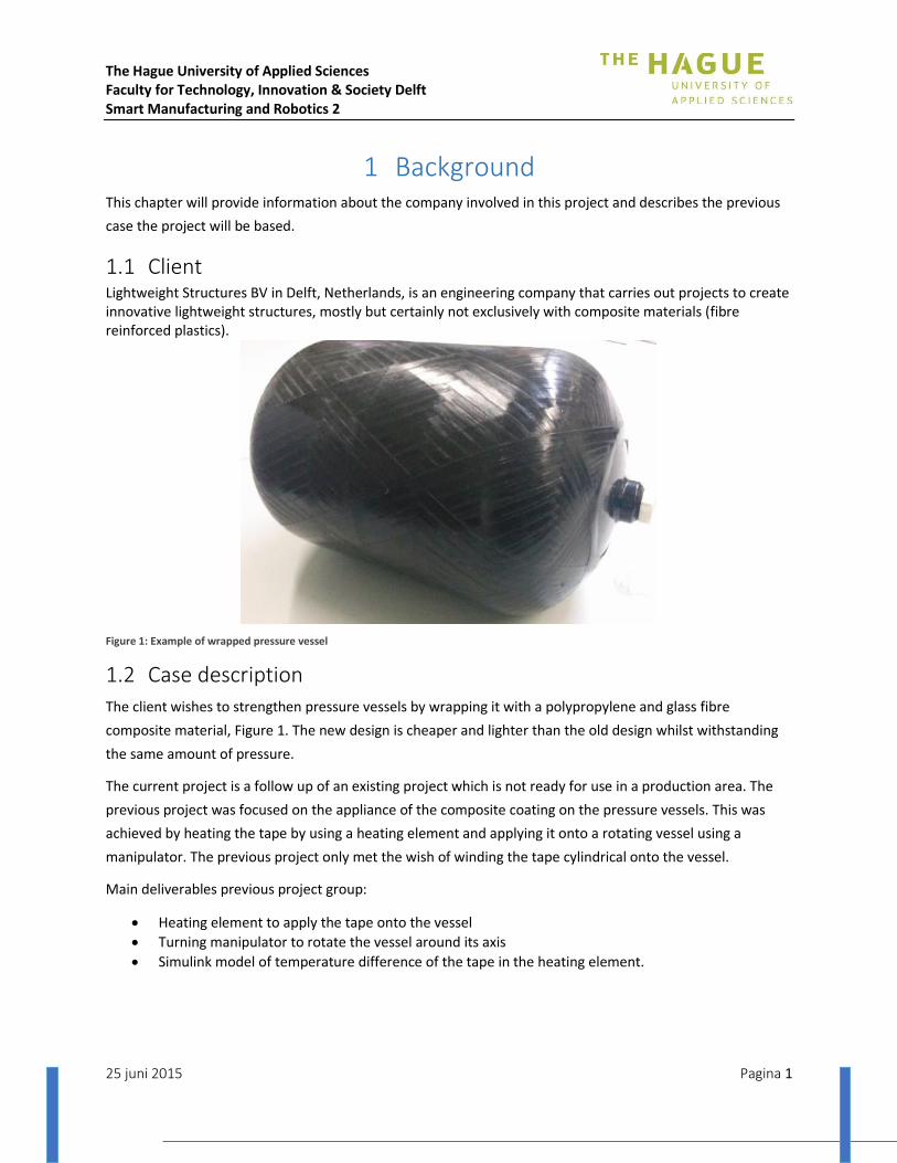
1.1 Client Lightweight Structures BV in Delft, Netherlands, is an engineering company that carries out projects to create innovative lightweight structures, mostly but certainly not exclusively with composite materials (fibre reinforced plastics).
Figure 1: Example of wrapped pressure vessel
1.2 Case description
The client wishes to strengthen pressure vessels by wrapping it with a polypropylene and glass fibre
composite material, Figure 1. The new design is cheaper and lighter than the old design whilst withstanding
the same amount of pressure.
The current project is a follow up of an existing project which is not ready for use in a production area. The
previous project was focused on the appliance of the composite coating on the pressure vessels. This was
achieved by heating the tape by using a heating element and applying it onto a rotating vessel using a
manipulator. The previous project only met the wish of winding the tape cylindrical onto the vessel.
Main deliverables previous project group:
Heating element to apply the tape onto the vessel
Turning manipulator to rotate the vessel around its axis
Simulink model of temperature difference of the tape in the heating element.

The Hague University of Applied Sciences Faculty for Technology, Innovation & Society Delft Smart Manufacturing and Robotics 2
25 juni 2015 Pagina 2
2 Project definition The project goal has always been to produce a system that could wind filament around a pressure vessel.
Although it took some time before all involved parties came to an agreement on what would be delivered at
the end of project. This chapter discusses the original and final goals which define the project.
Our predecessors have already built a frame and an End Of Arm Tool (EOAT) that could wind simple patterns.
The focus of our project was doing research. This research includes research on the cooling speed of the laid
filament, the heating of the filament whilst using a smaller EOAT provided by Lightweight Structures and
research on how to wind filament with the robots available.
After several meetings, new goals have been set. These new goals were due to an oversight as what had to
be done and what was already completed. The newly defined project still contained research but its focus
switched to optimizing the existing setup to make it capable of winding filament in a more complex pattern.
In order to have a fully functional system, multiple controllable parameters were required and with this in
mind the new goals were:
Redesigning the EOAT and determine its capabilities
Optimizing the manipulator control system
Make it possible to control the rotational speed of the pressure vessel
Built a prototype winding program
The project started with research to deduct what further steps had to be taken, followed by upgrading the
original manipulator and writing the program.
The Hague University of Applied Sciences Faculty for Technology, Innovation & Society Delft Smart Manufacturing and Robotics 2
25 juni 2015 Pagina 3
3 Pressure vessel manipulator This chapter describes the original setup left to us by our predecessors followed by what could be optimised.
The final part showcases the upgrade done during this project.
3.1 Original
The current setup of the vessel manipulator is made by previous SMR2 students. The most important
specifications of the vessel manipulator are shown.
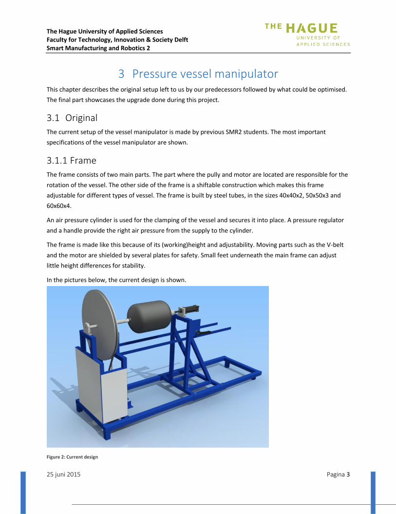
3.1.1 Frame
The frame consists of two main parts. The part where the pully and motor are located are responsible for the
rotation of the vessel. The other side of the frame is a shiftable construction which makes this frame
adjustable for different types of vessel. The frame is built by steel tubes, in the sizes 40x40x2, 50x50x3 and
60x60x4.
An air pressure cylinder is used for the clamping of the vessel and secures it into place. A pressure regulator
and a handle provide the right air pressure from the supply to the cylinder.
The frame is made like this because of its (working)height and adjustability. Moving parts such as the V-belt
and the motor are shielded by several plates for safety. Small feet underneath the main frame can adjust
little height differences for stability.
In the pictures below, the current design is shown.
Figure 2: Current design

The Hague University of Applied Sciences Faculty for Technology, Innovation & Society Delft Smart Manufacturing and Robotics 2
25 juni 2015 Pagina 4
3.1.2 Transmission, bearing and shaft
The motor side of the rotator contains the two sets of angular contact bearings. Between the two bearings a
pulley is mounted. A shaft connects these parts. The transmission of the mechanical energy goes from the
motor to the pulley via a v-belt and the pulley is attached to the shaft thus is able to make a rotational
movement.
The design uses angular bearings to rotate and hold radial forces of the pully. There is space left between the
shaft and the motor to accommodate to the specific needed speed the manipulator has to rotate. The output
from the motor is adjusted mechanically with a pulley and v-belt.
A 25 mm driveshaft is used. On the end of the drive shaft a fitting for the vessel is added. The pulley which will be used on the drive shaft, will have a diameter of 630 mm. This is needed to reduce the outgoing speed sharply. On the motor side a pulley of just 50 mm will be used.
3.1.3 Clamping
A pneumatic cylinder is used for clamping. It is a double-acting cylinder, because single-acting cylinders
cannot generate enough force to clamp these vessels. With a lever, the cylinder can be operated. On the end
of the piston-rod, there is made a mechanical system which will suspend the horizontal force and the
rotation of the vessel.
3.1.4 Motor
For the drive of the rotator a Siemen’s motor(D91066) is used in combination with an easy-drive frequency
controller (E2-202) to control the speed of the motor.

The Hague University of Applied Sciences Faculty for Technology, Innovation & Society Delft Smart Manufacturing and Robotics 2
25 juni 2015 Pagina 5
3.1.5 Total assembly
The current setup is working and controllable as stated, but not everything works well enough. This setup can
be used for more types of vessels. The current setup is not working good and accurate enough for the
applying of the tape on a particular type of vessel that is going to be used on this next task. Some
optimizations have to be made. The current assembly is as shown in Error! Reference source not found..
More specifications on the current setup are in appendix I.
Figure 3: The vessel manipulator
The Hague University of Applied Sciences Faculty for Technology, Innovation & Society Delft Smart Manufacturing and Robotics 2
25 juni 2015 Pagina 6
3.2 Optimization points
The frame made by another project group offers a good base for the manipulator. However, the frame does
not meet the necessary requirements in order for the project to succeed. Same changes have to be made in
order for the manipulator to work with the new pressure vessel setup.
3.2.1 The frame
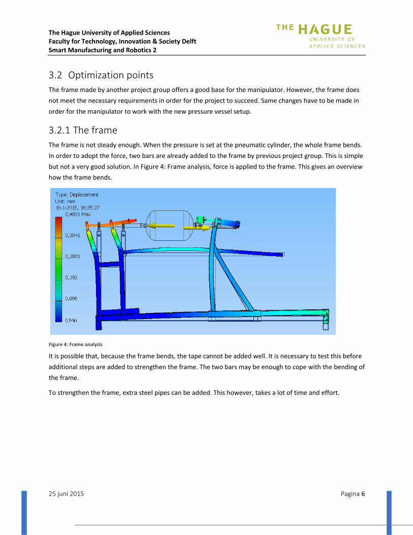
The frame is not steady enough. When the pressure is set at the pneumatic cylinder, the whole frame bends.
In order to adopt the force, two bars are already added to the frame by previous project group. This is simple
but not a very good solution. In Figure 4: Frame analysis, force is applied to the frame. This gives an overview
how the frame bends.
Figure 4: Frame analysis
It is possible that, because the frame bends, the tape cannot be added well. It is necessary to test this before
additional steps are added to strengthen the frame. The two bars may be enough to cope with the bending of
the frame.
To strengthen the frame, extra steel pipes can be added. This however, takes a lot of time and effort.

The Hague University of Applied Sciences Faculty for Technology, Innovation & Society Delft Smart Manufacturing and Robotics 2
25 juni 2015 Pagina 7
3.2.2 Peripherals
Aside from the frame, multiple peripherals of the manipulator can be optimized. These are; the motor,
encoder, rod, bearings and adapter.
Motor
The motor of the manipulator is not the right motor. The tape needs to be added at a low speed. The current
motor cannot deliver this low speed. The new motor has to be calculated.
Encoder
The robot needs to know exactly how much the pressure vessel rotates. Therefore, an encoder can be added
to the rod. This encoder can be part of the motor or can be added separate.
Rod
The current rod is too short in order to fit the new setup. By making a new rod, the new motor can be added
without making changes to the frame.
Bearings
The current bearings are not right bearings. The bearings were not fixed and not well aligned. Therefore
other bearing are necessary. A pillow block bearing is needed, because this type of bearing can be added
right to the frame. Also, the rod can be fixed in this bearing.
Adapter
To secure the pressure vessel, two different adapters have been made. A top adapter to secure the top side
(gap side) of the vessel. A bottom adapter to secure the bottom of the pressure vessel. Those two adapters
are 3d printed.
Figure 5: Bottom adapter(left)/ Top adapter (right)

The Hague University of Applied Sciences Faculty for Technology, Innovation & Society Delft Smart Manufacturing and Robotics 2
25 juni 2015 Pagina 8
3.2.3 Total assembly
The changes to the current frame are important optimizations. The new frame should be a lot more accurate.
The movement of the pressure vessel has to be as accurate as possible. As a result, the robot stick the tape
precisely on the pressure vessel.
The Hague University of Applied Sciences Faculty for Technology, Innovation & Society Delft Smart Manufacturing and Robotics 2
25 juni 2015 Pagina 9
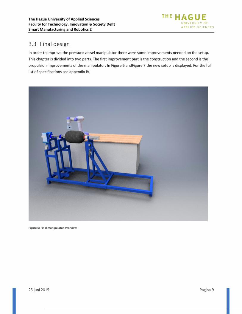
3.3 Final design
In order to improve the pressure vessel manipulator there were some improvements needed on the setup.
This chapter is divided into two parts. The first improvement part is the construction and the second is the
propulsion improvements of the manipulator. In Figure 6 andFigure 7 the new setup is displayed. For the full
list of specifications see appendix IV.
Figure 6: Final manipulator overview

The Hague University of Applied Sciences Faculty for Technology, Innovation & Society Delft Smart Manufacturing and Robotics 2
25 juni 2015 Pagina 10
3.3.1 Construction
This part will handle the constructional changes of the pressure vessel manipulator such as the frame, the
bearings and the driveshaft.
Frame
The motor is mounted on the frame by using a reaction compensation connection between the motor and
the side of the frame. This mounting has the purpose to keep the motor in the same position while rotation
the driveshaft. The technical drawings are in the appendix IX.
Bearings In order to support the shaft which will transfer the rotation of the engine onto the barrel, two tapped based
pillow blocks ‘UCPA 205’ bearings will be used. The technical datasheet is in the appendix X.
To align the bearings well with the current setup, small optimizations were made. Spacers and sheets are
added to the frame to fasten the bearings. Technical drawings of the production of these parts are in
appendix IX.
Driveshaft The driveshaft which will transfer the rotation of the motor onto the vessel is custom made for this
application. The diameter of the driveshaft which will go inside the reduction of the motor is 25mm. The
technical drawings are in appendix IX.
Figure 7: Final manipulator, front view
The Hague University of Applied Sciences Faculty for Technology, Innovation & Society Delft Smart Manufacturing and Robotics 2
25 juni 2015 Pagina 11
3.3.2 Propulsion
This second part will handle the propulsion improvements of the pressure vessel manipulator. These
improvements will cover the motor, the reduction, the encoder and the control of the motor.
Motor
The motor used for the rotation of the barrel is a 0,09 kW, M-series (M56b4) from Carpanelli, three phase
motor provided by ‘MAK aandrijvingen’. The motor has a rotation speed of 1360 rpm. The technical
datasheet is in appendix X.
The motor selection is chosen on the basis of several calculations. These calculations are in appendix III-1.
The research of the right motor is based on the calculations. The research can be found in appendix II.
Reduction
Because the application needs to rotate at really low speeds around 1 rpm, a great reduction is necessary to
slow the engine down to the required speeds. To achieve this reduction, a combination of two reductions is
used. The first one is the gear reduction ‘HW 030’ from ‘Motovario’. This gear reduction reduces the rotation
speed by 10,83. The second reduction, which is mounted directly onto the first one, is the worm reduction
‘NMRV-P 063’ from ‘Motovario’. This worm reduction reduces the rotation by 100. This reduction will be
attached to the driveshaft with a diameter of 25mm. Because the two reductions are combined, the final
reduction is 1083 (10,83 * 100 = 1083). The efficiency of this combined reduction is around 45% (gears: ± 90%
worm: ±50%). The technical datasheet is in appendix X.
Encoder
In order to control the system properly, there is a need to know at which speed or at which position the
barrel is. Therefor an encoder on the driveshaft is used. The encoder used is an incremental shaft encoder
type RI 32 from ‘Hengstler’. This encoder has a maximum pulse count of 1500 pulses. According to the
calculations in the annex this is sufficient enough for this application. The technical datasheet is in appendix
X. The encoder selection is chosen on the basis of several calculations. These calculations are in appendix III-
2.
3.3.3 Control
To control the motor, the frequency converter ‘E2-201-H1F’ from ’T-Verter’ will be used. The reach of the
frequency converter is from 1Hz till 200Hz. The frequency converter can be set manually or by means of a
variable input voltage on an input on the frequency controller. For this application we will use a variable
input voltage from the robot controller to alter the speed of the motor through the frequency converter. The
maximum rotation speed of the motor is 60Hz. Because the maximum rotation speed of the motor is 60Hz
the maximum frequency of the frequency controller has to be set to 60Hz. The technical datasheet is in
appendix X.
The frequency convertor is tested and developed. The test report is in appendix III-3.
The Hague University of Applied Sciences Faculty for Technology, Innovation & Society Delft Smart Manufacturing and Robotics 2
25 juni 2015 Pagina 12
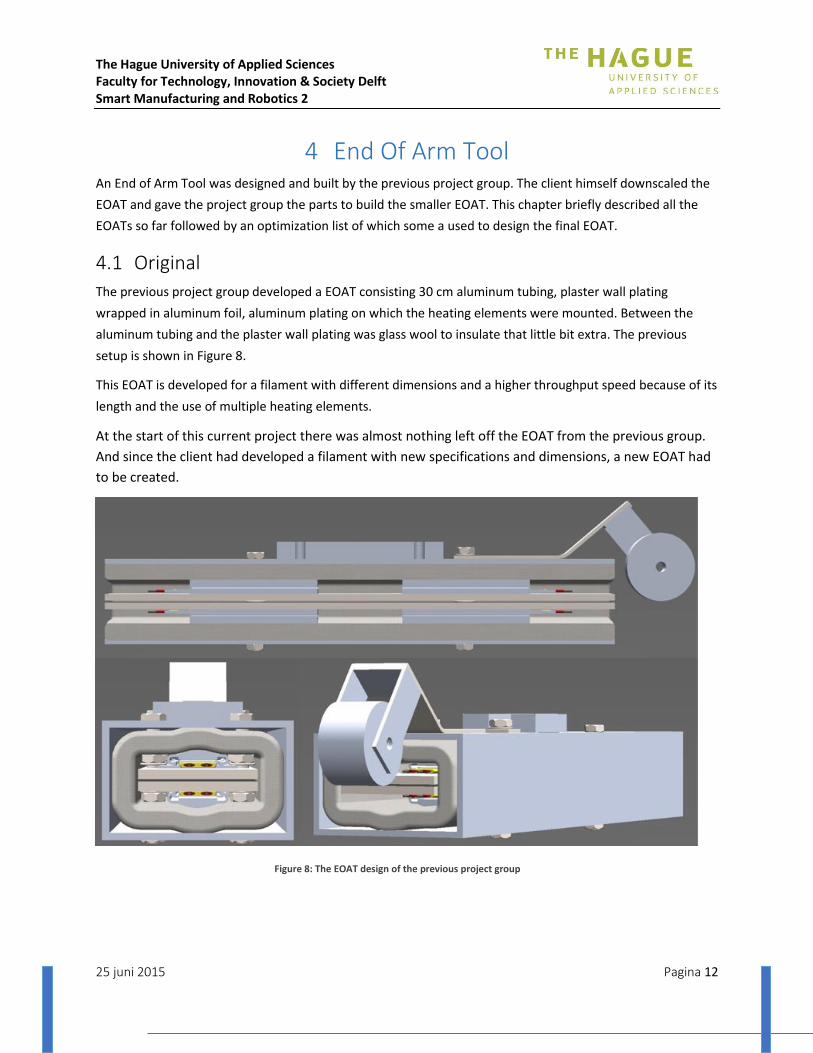
4 End Of Arm Tool An End of Arm Tool was designed and built by the previous project group. The client himself downscaled the
EOAT and gave the project group the parts to build the smaller EOAT. This chapter briefly described all the
EOATs so far followed by an optimization list of which some a used to design the final EOAT.
4.1 Original
The previous project group developed a EOAT consisting 30 cm aluminum tubing, plaster wall plating
wrapped in aluminum foil, aluminum plating on which the heating elements were mounted. Between the
aluminum tubing and the plaster wall plating was glass wool to insulate that little bit extra. The previous
setup is shown in Figure 8.
This EOAT is developed for a filament with different dimensions and a higher throughput speed because of its
length and the use of multiple heating elements.
At the start of this current project there was almost nothing left off the EOAT from the previous group.
And since the client had developed a filament with new specifications and dimensions, a new EOAT had
to be created.
Figure 8: The EOAT design of the previous project group
The Hague University of Applied Sciences Faculty for Technology, Innovation & Society Delft Smart Manufacturing and Robotics 2
25 juni 2015 Pagina 13
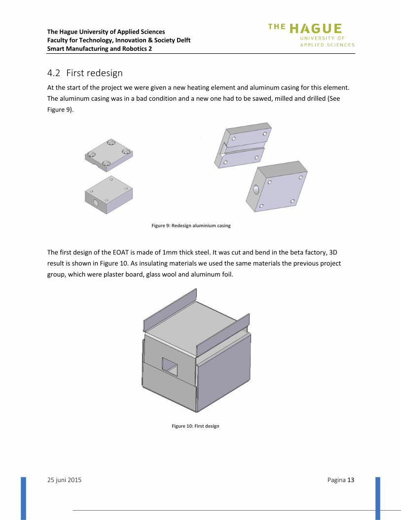
4.2 First redesign
At the start of the project we were given a new heating element and aluminum casing for this element.
The aluminum casing was in a bad condition and a new one had to be sawed, milled and drilled (See
Figure 9).
The first design of the EOAT is made of 1mm thick steel. It was cut and bend in the beta factory, 3D
result is shown in Figure 10. As insulating materials we used the same materials the previous project
group, which were plaster board, glass wool and aluminum foil.
Figure 9: Redesign aluminium casing
Figure 10: First design
The Hague University of Applied Sciences Faculty for Technology, Innovation & Society Delft Smart Manufacturing and Robotics 2
25 juni 2015 Pagina 14
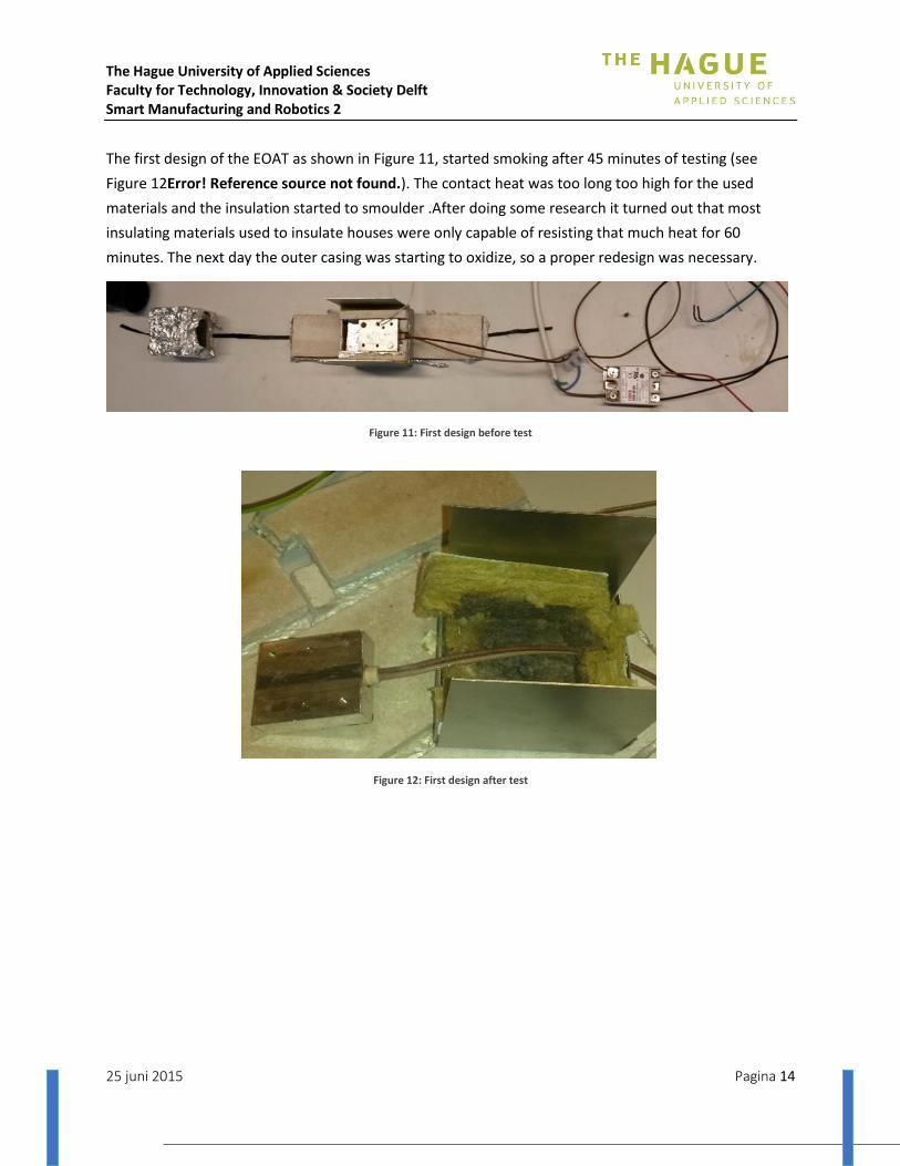
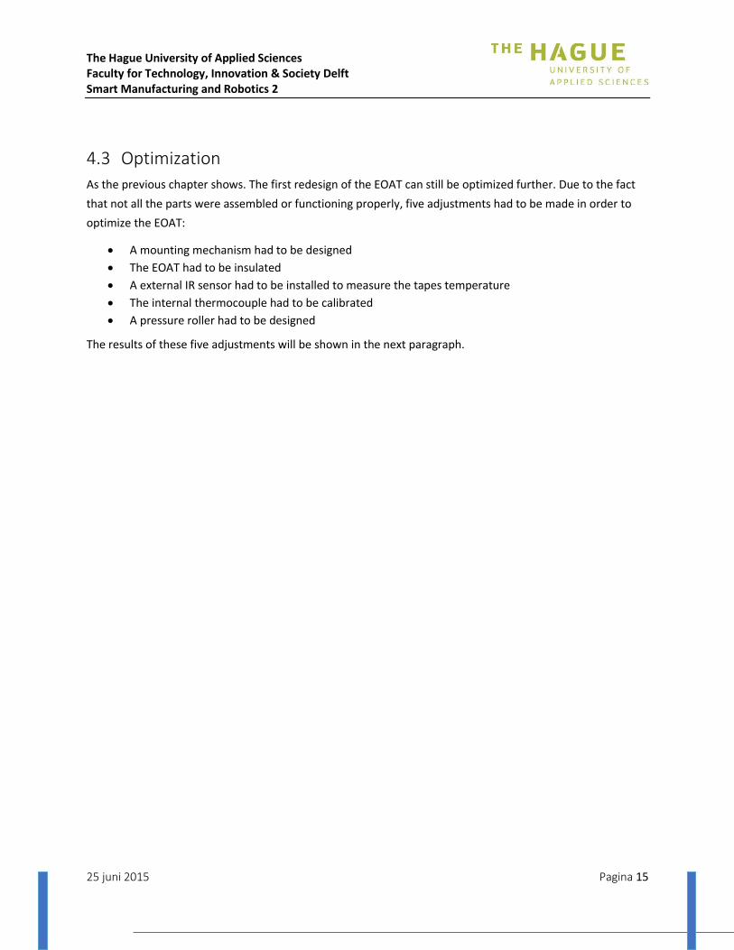
The first design of the EOAT as shown in Figure 11, started smoking after 45 minutes of testing (see
Figure 12Error! Reference source not found.). The contact heat was too long too high for the used
materials and the insulation started to smoulder .After doing some research it turned out that most
insulating materials used to insulate houses were only capable of resisting that much heat for 60
minutes. The next day the outer casing was starting to oxidize, so a proper redesign was necessary.
Figure 11: First design before test
Figure 12: First design after test
The Hague University of Applied Sciences Faculty for Technology, Innovation & Society Delft Smart Manufacturing and Robotics 2
25 juni 2015 Pagina 15
4.3 Optimization
As the previous chapter shows. The first redesign of the EOAT can still be optimized further. Due to the fact
that not all the parts were assembled or functioning properly, five adjustments had to be made in order to
optimize the EOAT:
A mounting mechanism had to be designed
The EOAT had to be insulated
A external IR sensor had to be installed to measure the tapes temperature
The internal thermocouple had to be calibrated
A pressure roller had to be designed
The results of these five adjustments will be shown in the next paragraph.

The Hague University of Applied Sciences Faculty for Technology, Innovation & Society Delft Smart Manufacturing and Robotics 2
25 juni 2015 Pagina 16
4.4 Final design
In the final design the following requirements had to be implemented:
1. Outer casing made of a material that would not oxidize;
2. Casing consists of a top part and bottom part;
3. The top part must be mounted to the robot arm so only the bottom part needs to be unbolted
when servicing the EOAT;
4. At least 2 cm of spacing between the outer casing and the aluminum block all around;
5. Finding an insulating material that is capable of resisting the temperature at all times.
These requirements came forth out of testing the first redesign of the EOAT.
In Figure 13 is shown how the casing and lit are two different parts. Error! Reference source not found.
shows how the casing and lit are assembled. Figure 8 is the complete assembly, excluding the insulating
material.
Figure 13: Final design consisting of casing and cover
Figure 15: Assembly casing and cover Figure 14: Casing and cover assembled with heating element and robot mount

The Hague University of Applied Sciences Faculty for Technology, Innovation & Society Delft Smart Manufacturing and Robotics 2
25 juni 2015 Pagina 17
4.4.1 Material choice
The material choice for the outer casing was not as difficult. The choice was AlMg3, this was available and
good for welding and bending.
To inquire more information about insulating materials several hardware stores were visited and asked if
they could provide a material that could withstand the heat generated by the heating element. And the
lengthy duration of the heating process.
All of them confirmed that the previously used material and every other material used for the insulation of
houses would not meet the requirements. Even those that did meet the heating requirement could not
handle the heat for longer than sixty minutes without degrading and losing their insulating properties.
In the end a hearth salesman gave the advice to use a material for hearths which resulted into a gift of a
board of Super Isol. The hearth salesman uses it to stick it between the wooden walls and the stone tiles in a
fireplace. Stone tiles do not insulate at all which means the board of Super Isol prevents the wood from
getting hot or burning.
For the full report see appendix V
4.4.2 Temperature sensor
To measure the temperature of the tape leaving the heating element a temperature sensor is needed. From
all the possible sensors that are available an IR-sensor is seen as the best solution. Two of those sensors were
considered. After the initial sensor of our choice, the TI TMP007, was dead on arrival so another sensor was
used. This Melexis MLX90614 IR-sensor was initially tested using ice-water and nearly boiling water. When
the sensor was believed to work correctly it was put up against our reference sensor, de Testo 835-T2.
The MLX90614 was tested by heating tape with a soldering iron and comparing the results with the
reported temperature of the Testo sensor. At 5mm, 11mm and 28mm distance between tape and the
Melexis sensor the results were compared. Only the 5mm and 11mm distances gave good results. At those
distances and at lower temperatures (< 60 °C) the differences were only a few degrees. At higher
temperatures (> 65 °C) the Melexis sensor reported up to a 17 °C higher temperature when the result was
102,6 °C versus 85 °C as measured by the Testo.
The tests have proven that this Melexis sensor can be used for the purpose of measuring the tape
temperature at a distance of 5mm and 11mm. However, when using the sensor in the final product the
Melexis results will have to be calibrated to compensate for the over reported temperature at higher
temperatures.
For the full research see appendix VII.
The Hague University of Applied Sciences Faculty for Technology, Innovation & Society Delft Smart Manufacturing and Robotics 2
25 juni 2015 Pagina 18
5 Filament properties The use of PP-glass fibre tape is a relatively new in the market. Due to the lack of information and references
research had to be done in order to gather the correct information to fulfil the assignment. Our predecessors
have already done some research on the subject, but at the start of the project to mayor changes were made
to the EOAT and filament.
First the size of the EOAT and heating element were decreased from a 150mm long block with a heating
capacity of about 1000W to an aluminium block of about 50 mm with a heating capacity of 250W.
Secondly the PP-glass fibre tape was decreased in size from 20mm in width to 5mm. In order to use both in
the project research had to be done on the following:
- Heating capacity of the EOAT
- Insulation of the aluminium block
- PP-glass fibre tape material specifications
- Operating temperature
The answers and the research report itself can be found in Appendix VI.

The Hague University of Applied Sciences Faculty for Technology, Innovation & Society Delft Smart Manufacturing and Robotics 2
25 juni 2015 Pagina 19
6 Winding path The winding path of the filament onto the pressure vessel is rather complex and therefore this chapter first
explain the mathematics behind the program followed by the program itself.
6.1 Relation EOAT and PVM
The composite tape needs to be applied following a geodesic curve, the shortest path from one point to
another, preventing the tape to slip of the pressure vessel. Applying the tape following a geodesic curve
means the End-Of-Arm-Tool (EOAT) and Pressure Vessel Manipulator (PVM) need to operate related to each
other. In order to determine this relation some assumptions have to be made:
Composite tape will be applied on top of the pressure vessel as shown in Figure 16. This creates a
plane to determine the needed rotation of the PVM in relation to the EOAT.
Figure 16: Line for applying tape to pressure vessel

The Hague University of Applied Sciences Faculty for Technology, Innovation & Society Delft Smart Manufacturing and Robotics 2
25 juni 2015 Pagina 20
The actual geodesic curve with an angle of 25 degree to the rotation axis is assumed by three
projected planes. The cross section of these projected planes are shown in Figure 17. This
assumption makes it possible to create a three dimensional path across the surface of the pressure
vessel. Though the actual geodesic path is not exactly 360 degrees, the result of the assumed pattern
can be multiplied to conform to the needed geodesic path.
Figure 17: Projected assumpted geodesic curve
The above mentioned assumptions make it possible to determine the needed rotation angle of the PVM and
to derive a path from the CAD-model. First, points with a distance of 1,2cm are generated to create the
necessary path as shown in Figure 18.
Figure 18: Created path across the surface of the pressure vessel CAD model
The created path is then exported manually into a spreadsheet, shown in Spreadsheet path coordinates. The
coordinates are used to calculate the rotation angle at the cross section of every coordinate, as shown in
Figure 19.

The Hague University of Applied Sciences Faculty for Technology, Innovation & Society Delft Smart Manufacturing and Robotics 2
25 juni 2015 Pagina 21
Figure 19: Cross Section determine angle related to applying tape
With the calculation of the rotation angles the relation between the movement of the EOAT and the rotation
of the PVM is determined. This relation is presented in Figure 20.
Figure 20: Relation rotation PVM and movement EOAT

The Hague University of Applied Sciences Faculty for Technology, Innovation & Society Delft Smart Manufacturing and Robotics 2
25 juni 2015 Pagina 22
The condition for applying composite tape at constant speed makes clear the variable time has to be
introduced. Because the distance between the coordinates of the path is equal, each step requires an equal
amount of time for constant speed of applying tape. Figure 21 shows the movement of the EOAT and
rotation of the PVM related to time. There needs to be noted: Units different than SI-units are used to
present both diagrams in the same figure.
Figure 21: Movement EOAT and rotation PVM related to time
Figure 21 makes clear the PVM adapts speed to compensate the movement of the EOAT. The middle of the
diagram shows how the EOAT almost stops moving while the PVM is rotating, meaning the pole of the
winding is reached (bottom or top of the pressure vessel). This movement makes it possible to follow a
geodesic path around the pressure vessel.

The Hague University of Applied Sciences Faculty for Technology, Innovation & Society Delft Smart Manufacturing and Robotics 2
25 juni 2015 Pagina 23
6.2 Robot code
To get the heated tape correctly wound around the pressure vessel the head needs to follow a certain
trajectory. This accomplished by attaching the head to a robot arm.
The robot will supply translation over two axes and rotation around two axes. Rotation of the vessel around
its own center axis makes sure the other translation and rotation are managed.
Approach
This approach gives the easiest way to process the wrap trajectory of the tape around the vessel. It means
the robot however will only move through one given plane. In the case of the test subject this is the XZ-plane.
Two ways were determined how to control the robots movements; TCP location wise or formula wise.
Location
A string of locations could be exported from a step-file using Inventor. These can then be entered into the
robot program and simply let the robot attend all poses subsequently. However this is the easiest approach
to a complex problem it offers very little room for adjustments and the change to another vessel would mean
a lot of work.
Formula
Option two offers more flexibility but needs more skill to figure out what need to be done. Luckily the design
of the vessel is relatively easy to follow. The contours exist of two parts of an arc circle and a straight line.
This is relatively easy to program and can (when variables are used) be easily adjusted to ensure maximum
compatibility. 1
1
2
2
3
3
4
4
5
5
6
6
A A
B B
C C
D D
ASSY-10X17-DWE
Sjorsbob 17-06-15
Designed by Checked by Approved by Date
1 / 1 Edition Sheet
Date
R128,00
r =
168,00l =
21,8
5°
Angle
_st
art
=
teta
dx
Wrap_start
Figure 22: cross-section of the vessel shown multiple variables used in the robot code

The Hague University of Applied Sciences Faculty for Technology, Innovation & Society Delft Smart Manufacturing and Robotics 2
25 juni 2015 Pagina 24
6.3 Program
The program exists of a several different sub programs. These are: Before start, calculate pose values, assign
pose values, execute move, Read encoder, calculate PID response and execute PID response.
Below is shown a PFD that show the contents of the main program that controls the robot.
Before start
Set all values to standard value
Move to position Wrap_start + 200m in Z-direction
Main program
Set x : To cos(tetaY)*r+dx
Set y = 0
Set z = sin(tetaY)*r
Set rx = 0
Set ry = 0,5*pi-tetaY
Set rz = tetaZ
Jmove to Wrap_start + (x, y, z, rx, ry, rz)
If Wrap_back == False
If tetaY < 0,5*pi, x>-l, tetaY < pi-Angle_start_Y, else If
Reverse of everything left Recalculate tetaY
Recalculate tetaZ
teta = 0,5pi
tetaZ = Angle_Z
dx=x–l/Stap_recht
Telrecht ++
Recalculate tetaY
Recalculate tetaZ
Wrap_back = True
Return Main

The Hague University of Applied Sciences Faculty for Technology, Innovation & Society Delft Smart Manufacturing and Robotics 2
25 juni 2015 Pagina 25
7 Conclusion and recommendations It is possible to strengthen pressure vessel by wrapping it with a polypropylene and glass fiber composite
material. This can be done if the following components are working well:
7.1 Pressure vessel manipulator
The pressure vessel manipulator is responsible for turning and clamping the pressure vessel. Due to a
frequency controller, the robot can communicate with the pressure vessel manipulator in terms of rotation
speed. This is necessary for the tape winding path. The pressure vessel manipulator is still adjustable for
future productions of other types of vessel. It may be necessary to design new adapters in order to fit the
different pressure vessels.
Make sure that frame is fixed while winding. This can be done by the fixing screws at the bottom of the
frame. It is also recommended to check if the vessel is properly placed before starting to wind. Don’t let the
pressure vessel fall after winding and releasing the vessel by lowering the air pressure. This may break the
adapter, different parts of the machine or even the vessel. It is also recommended to screw the white shell
into the pressure vessel before fixing it in the manipulator. Hold the pressure vessel steady at the right height
when applying air pressure on the cylinder for clamping.
7.2 End Of Arm Tool
By redesigning the EOAT tool and determine its capabilities, it was clear that the newly designed EAOT was
much better suited than the previous prototype. This new EOAT is heating the tape and measuring its
temperature. The EAOT is well insulated and ensures a good flow of the outgoing tape.
The tape width is 5 mm and the EAOT is made for this size of tape. It is recommend that only this type of tape
is used. When using other types of tape, it is necessary to test this tape and/or design a new EAOT.
When heating the tape, smoke is coming of the EOAT. This smoke may contain toxic chemicals so a good
extraction is recommended. It is possible to suck away this smoke right at the exit of the outgoing tape, by
holding or attaching a vacuum cleaner next to it.
The EAOT is well insulated but some heat is still coming of the EAOT, especially the outgoing tape. Don’t get
to close to the EOAT for safety reasons (burning and toxic air). Don’t touch the EOAT or other parts of the
robot while functioning. This can deviate the robot from its path or hurt people around.
It is also recommend to bring the EOAT as close to the pressure vessel as possible. This is important because
the heated tape will cool down between the EOAT and the vessel. If the tape is to cold it may not stick well
enough to stay. If the tape becomes too hot it may break, so rising the temperature of the EAOT is not a good
solution.

The Hague University of Applied Sciences Faculty for Technology, Innovation & Society Delft Smart Manufacturing and Robotics 2
25 juni 2015 Pagina 26
7.3 Winding path
The winding path is important for the strength of the pressure vessel after winding. To make sure the
pressure vessel is correctly winded, the robot and the manipulator must work together seamlessly. The path
covered by the robot is important for the final path of the tape.
The path the robot follows is approximately the correct path. The path is an assumption of the correct path
by an angle of 25 degrees. This path is been devised for this particular vessel. A mathematical model or other
assumption has to be made if other pressure vessels are going to be used.

The Hague University of Applied Sciences Faculty for Technology, Innovation & Society Delft Smart Manufacturing and Robotics 2
25 juni 2015 Pagina 27
Appendix I: Original manipulator specifications The current setup of the vessel rotator is made by SMR2 students before. To understand their decisions, it
was necessary to look up their reports. Most of the information of the specifications of the rotator is based
on their information and tests. It is necessary to test those results ourselves to be sure of those results. The
most important specifications of the vessel rotator are shown.
1. General overview
In the pictures below, the final design is shown.
Figure 23: Final Inventor design
A pneumatic cylinder is used for clamping. To hold the drive shaft two bearings are used. On the left it is a
simple ball bearing to suspend the down force which will be generated by the pulley, which will be place
between the two bearings. The bearing on the right is an angular contact bearing, which will suspend down
force, but also the horizontal force which is given by the cylinder to clamp the vessel. On the end of the drive
shaft a fitting for the vessel is added. The pulley which will be used on the drive shaft, will have a diameter of
630 mm. This is needed to reduce the outgoing speed sharply. On the motor side a pulley of just 50 mm will
be used.
On the other side of the drive shaft, the pneumatic cylinder is added. It is a double-acting cylinder, because
single-acting cylinders cannot generate enough force to clamp these vessels. With a lever, the cylinder can be
operated. On the end of the piston-rod, there is made a mechanical system which will suspend the horizontal
force and the rotation of the vessel.
The Hague University of Applied Sciences Faculty for Technology, Innovation & Society Delft Smart Manufacturing and Robotics 2
25 juni 2015 Pagina 28
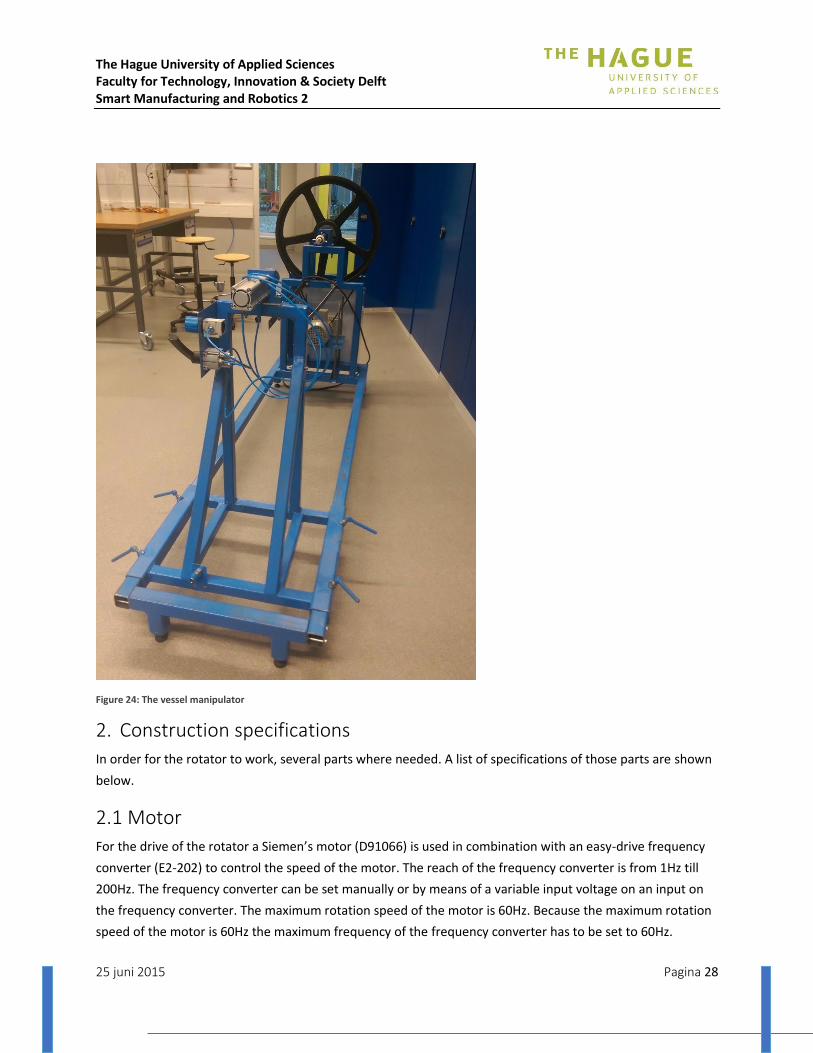
Figure 24: The vessel manipulator
2. Construction specifications
In order for the rotator to work, several parts where needed. A list of specifications of those parts are shown
below.
2.1 Motor
For the drive of the rotator a Siemen’s motor (D91066) is used in combination with an easy-drive frequency
converter (E2-202) to control the speed of the motor. The reach of the frequency converter is from 1Hz till
200Hz. The frequency converter can be set manually or by means of a variable input voltage on an input on
the frequency converter. The maximum rotation speed of the motor is 60Hz. Because the maximum rotation
speed of the motor is 60Hz the maximum frequency of the frequency converter has to be set to 60Hz.
The Hague University of Applied Sciences Faculty for Technology, Innovation & Society Delft Smart Manufacturing and Robotics 2
25 juni 2015 Pagina 29
2.2 Transmission, bearing and shaft
The motor side of the rotator contains the two sets of angular contact bearings. Between the two bearings a
pulley is mounted. A shaft connects these parts. The transmission of the mechanical energy goes from the
motor to the pulley via a v-belt and the pulley is attached to the shaft thus is able to make a rotational
movement.
The design uses angular bearings to rotate and hold radial forces. When a force comes through the shaft the
angular bearing prevents the shaft from slipping through bearing. There is space left between the shaft and
the motor to accommodate to the specifics needs in speed the rotator has to rotate. The output from the
motor is adjusted mechanically with a pulley and a v-belt.
2.3 Frame, materials and conservation
The frame is built by steel tubes, in the sizes 40x40x2, 50x50x3 and 60x60x4.
To prevent this steel frame for any rust a surface treatment is added. Because of that this machine is a
demonstration machine, the treatment has no other reason but rust prevention. Therefore, there is chosen
for paint.
2.4 Clamping
There are two types of clamps that are used in the design. A fitting and a pneumatic cylinder. The fitting is
fastened on the shaft. The pneumatic cylinder is mounted on the construction with a steel block. The fitting
holds the force from the pneumatic cylinder. The vessel connects to the fitting and the pneumatic cylinder
presses against the vessel. The fitting centres the vessel through the opening of the vessel. The pneumatic
cylinder has a support at the end of the piston with a bearing for rotating. Between each clamping and the
vessel there is a rubber pad that uses the friction forces to not let the vessel slip.
The Hague University of Applied Sciences Faculty for Technology, Innovation & Society Delft Smart Manufacturing and Robotics 2
25 juni 2015 Pagina 30
3. Pneumatic and electrical specifications
In order to understand the pneumatics and electrical components used in the current setup the schemes of
the different product groups are necessary.
3.1 Pneumatic scheme
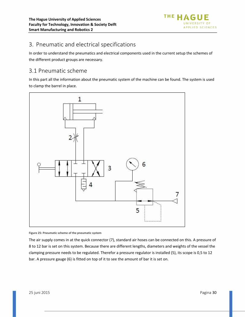
In this part all the information about the pneumatic system of the machine can be found. The system is used
to clamp the barrel in place.
Figure 25: Pneumatic scheme of the pneumatic system
The air supply comes in at the quick connector (7), standard air hoses can be connected on this. A pressure of
8 to 12 bar is set on this system. Because there are different lengths, diameters and weights of the vessel the
clamping pressure needs to be regulated. Therefor a pressure regulator is installed (5), its scope is 0,5 to 12
bar. A pressure gauge (6) is fitted on top of it to see the amount of bar it is set on.
The Hague University of Applied Sciences Faculty for Technology, Innovation & Society Delft Smart Manufacturing and Robotics 2
25 juni 2015 Pagina 31
To control the pneumatic piston (1) a 4/3 valve (3) is used. The valve is hand-operated by a handle. A 4/3
valve has 4 connections to put components on and 3 positions. 3 positions are ideal for this system, the
piston can be opened, closed and locked. From the 4/3 valve two connections go to the piston (1). On the
outgoing connection of the piston (1) a speed controller (2) is placed so the stroke of the piston is going
smoothly and can be controlled better. One connection on the 4/3 valve is an exhaust to release the
pressure. To prevent loud noises of escaping air, a muffler (4) is placed in the connection.
The system is connected with ¼ pluggable couplings where 6mm flexible tube can be put in.
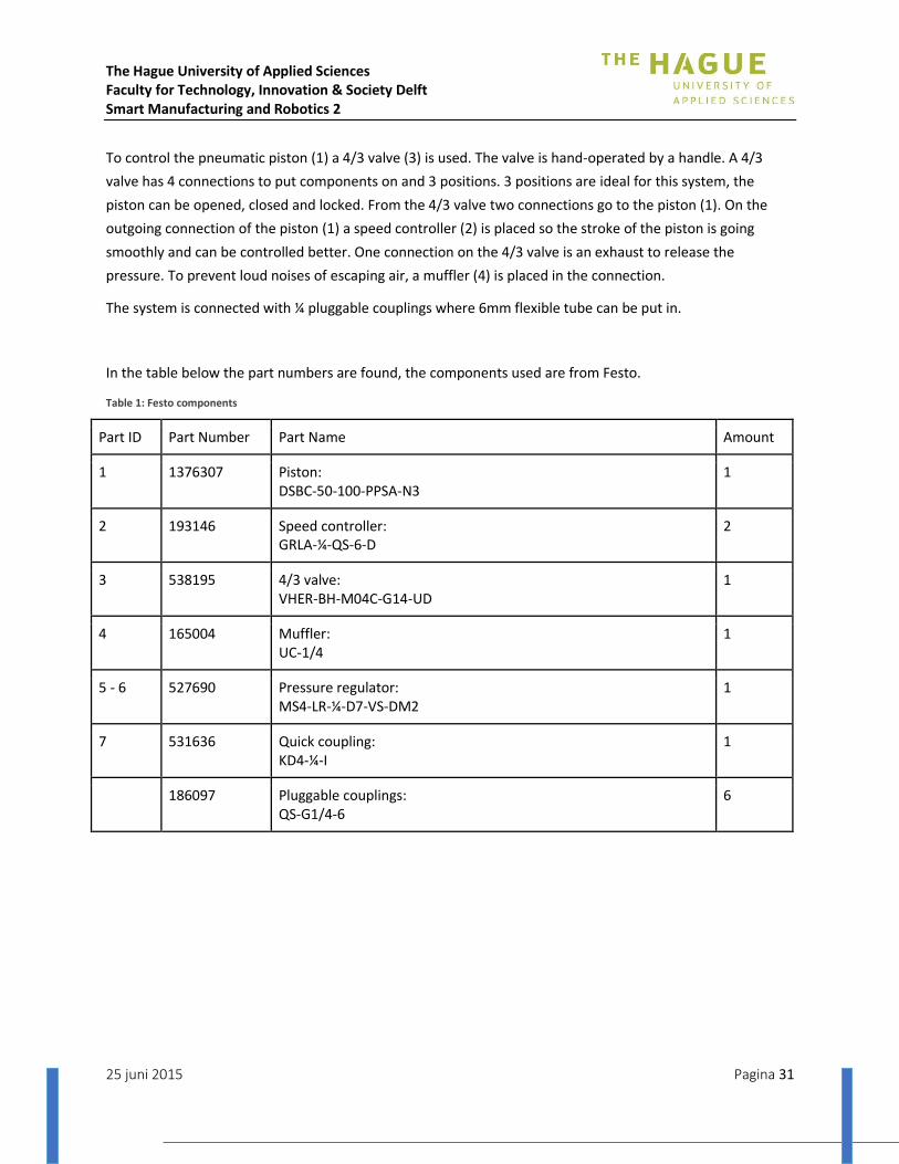
In the table below the part numbers are found, the components used are from Festo.
Table 1: Festo components
Part ID Part Number Part Name Amount
1 1376307 Piston: DSBC-50-100-PPSA-N3
1
2 193146 Speed controller: GRLA-¼-QS-6-D
2
3 538195 4/3 valve: VHER-BH-M04C-G14-UD
1
4 165004 Muffler: UC-1/4
1
5 - 6 527690 Pressure regulator: MS4-LR-¼-D7-VS-DM2
1
7 531636 Quick coupling: KD4-¼-I
1
186097 Pluggable couplings: QS-G1/4-6
6

The Hague University of Applied Sciences Faculty for Technology, Innovation & Society Delft Smart Manufacturing and Robotics 2
25 juni 2015 Pagina 32
3.2 Electronic scheme rotator
This part contains the information of the electronic components and how they are connected.
Figure 26: Electrical scheme
To connect the frequency controller to the robot-controller 4 pins from the robot controller are needed. Two
pins are needed to determine the rotation way of the motor. If voltage is put on pin 3 of the frequency
controller the motor will turn left, if voltage is put on pin 4 the motor will turn right. If there is voltage on
both pin 3 and 4 the motor will not turn. 24V is needed from the robot controller for the emergency stop,
which is connected to pin 6 of the frequency controller. The emergency stop is a normally closed connection,
so if the emergency stop is pushed the frequency controller get a signal on pin 6 and the motor stops
running. Pin 10 of the frequency controller is connected to the ground of the robot controller.

The Hague University of Applied Sciences Faculty for Technology, Innovation & Society Delft Smart Manufacturing and Robotics 2
25 juni 2015 Pagina 33
3.3 Frequency controller settings
The frequency controller has multiple parameters who needs to be set to the right value. The setting can be
set on the display of the frequency controller.
Figure 27: Frequency display
The parameters are set by pushing the DSP/FUN button and move to the right parameter with the up and
down buttons. If you navigate to the right parameter then press the DATA/END button and set the
parameter to the right value by the up and down buttons. If the parameter is set on the right value, press the
DATA/END button again and the parameter is set.
The parameters on the frequency controller that needs to be set to work together with the robot controller
are the parameters F06, F07, F10, F11, and F19.
- The parameter F06 has to be set on 50Hz to determine the maximum frequency.
- The parameter F07 has to be set on 0Hz to determine the minimum frequency.
- The parameter F10 has to be set on 1 to do the controls through the external clamps.
- The parameter F11 has to be set on 0 to set the speed by the pushbuttons on the frequency
controller.
- The parameter F19 has to be set on 3 to activate the emergency stop on clamp 6.

The Hague University of Applied Sciences Faculty for Technology, Innovation & Society Delft Smart Manufacturing and Robotics 2
25 juni 2015 Pagina 34
Appendix II: Manipulator optimization
RESEARCH MOTOR, ENCODER AND FREQUENCY CONVERTER
The goal of this research is to explore the possibilities of changes which could be made according to the
rotation of the vessel. For the rotation of the vessel there are different parts needed. The research will start
with the motor. This is a critical part for the application because it gives the necessary rotation to the vessel.
All motors have a rotation speed which is too high for this application. Therefore a reduction of the motor
speed is needed. For the control system there are two more parts needed. An encoder which can determine
where the vessel is or at what speed the vessel rotates. In order to be able to control the rotation of the
motor there is a controlling device necessary to alter the rotation speed of the motor when required.
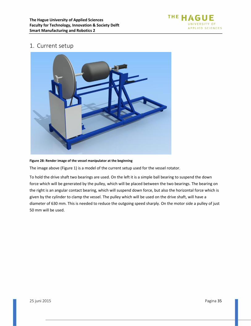
The Hague University of Applied Sciences Faculty for Technology, Innovation & Society Delft Smart Manufacturing and Robotics 2
25 juni 2015 Pagina 35
1. Current setup
Figure 28: Render image of the vessel manipulator at the beginning
The image above (Figure 1) is a model of the current setup used for the vessel rotator.
To hold the drive shaft two bearings are used. On the left it is a simple ball bearing to suspend the down
force which will be generated by the pulley, which will be placed between the two bearings. The bearing on
the right is an angular contact bearing, which will suspend down force, but also the horizontal force which is
given by the cylinder to clamp the vessel. The pulley which will be used on the drive shaft, will have a
diameter of 630 mm. This is needed to reduce the outgoing speed sharply. On the motor side a pulley of just
50 mm will be used.
The Hague University of Applied Sciences Faculty for Technology, Innovation & Society Delft Smart Manufacturing and Robotics 2
25 juni 2015 Pagina 36
2. Construction specifications
2.1 Motor
For the drive of the rotator a Siemen’s motor (D91066) is used in combination with an easy-drive frequency
controller (E2-202) to control the speed of the motor. The reach of the frequency controller is from 1Hz till
200Hz. The frequency controller can be set manually or by means of a variable input voltage on an input on
the frequency controller. The maximum rotation speed of the motor is 60Hz. Because the maximum rotation
speed of the motor is 60Hz the maximum frequency of the frequency controller has to be set to 60Hz.
2.2 Transmission, bearing and shaft
The motor side of the rotator contains the two sets of angular contact bearings. Between the two bearings a
pulley is mounted. A shaft connects these parts. The transmission of the mechanical energy goes from the
motor to the pulley via a v-belt and the pulley is attached to the shaft thus is able to make a rotational
movement.
The design uses angular bearings to rotate and hold radial forces. When a force comes through the shaft the
angular bearing prevents the shaft from slipping through bearing. There is space left between the shaft and
the motor to accommodate to the specifics needs in speed the rotator has to rotate. The output from the
motor is adjusted mechanically with a pulley and a v-belt.

The Hague University of Applied Sciences Faculty for Technology, Innovation & Society Delft Smart Manufacturing and Robotics 2
25 juni 2015 Pagina 37
3. Improvements
There are some improvements possible and necessary in order to make the vessel rotate at the desired
speeds around 1 rpm and be able to control it in a proper way. In the next paragraphs there will be an
enumeration for each part which will be improved. For each part there will be given multiple options which
their pro’s and con’s for each option. For each part needed to be improved there will be a trade-off matrix to
choose the best option considering the requirements for each part.
After the choice of the individual parts the final concept will be displayed by using a morphologic chart where
it is clear which parts will be combined into the final concept.
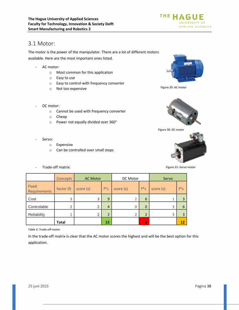
The Hague University of Applied Sciences Faculty for Technology, Innovation & Society Delft Smart Manufacturing and Robotics 2
25 juni 2015 Pagina 38
3.1 Motor:
The motor is the power of the manipulator. There are a lot of different motors
available. Here are the most important ones listed.
- AC motor:
o Most common for this application
o Easy to use
o Easy to control with frequency converter
o Not too expensive
- DC motor:
o Cannot be used with frequency converter
o Cheap
o Power not equally divided over 360°
- Servo:
o Expensive
o Can be controlled over small steps
- Trade-off matrix:
Concepts AC Motor DC Motor Servo
Fixed Requirements
factor (f) score (s) f*s score (s) f*s score (s) f*s
Cost 3 3 9 2 6 1 3
Controlable 2 2 4 0 0 3 6
Reliability 1 2 2 2 2 3 3
Total 15 8 12
Table 2: Trade-off motor
In the trade-off matrix is clear that the AC motor scores the highest and will be the best option for this
application.
Figure 29: AC motor
Figure 30: DC motor
Figure 31: Servo motor
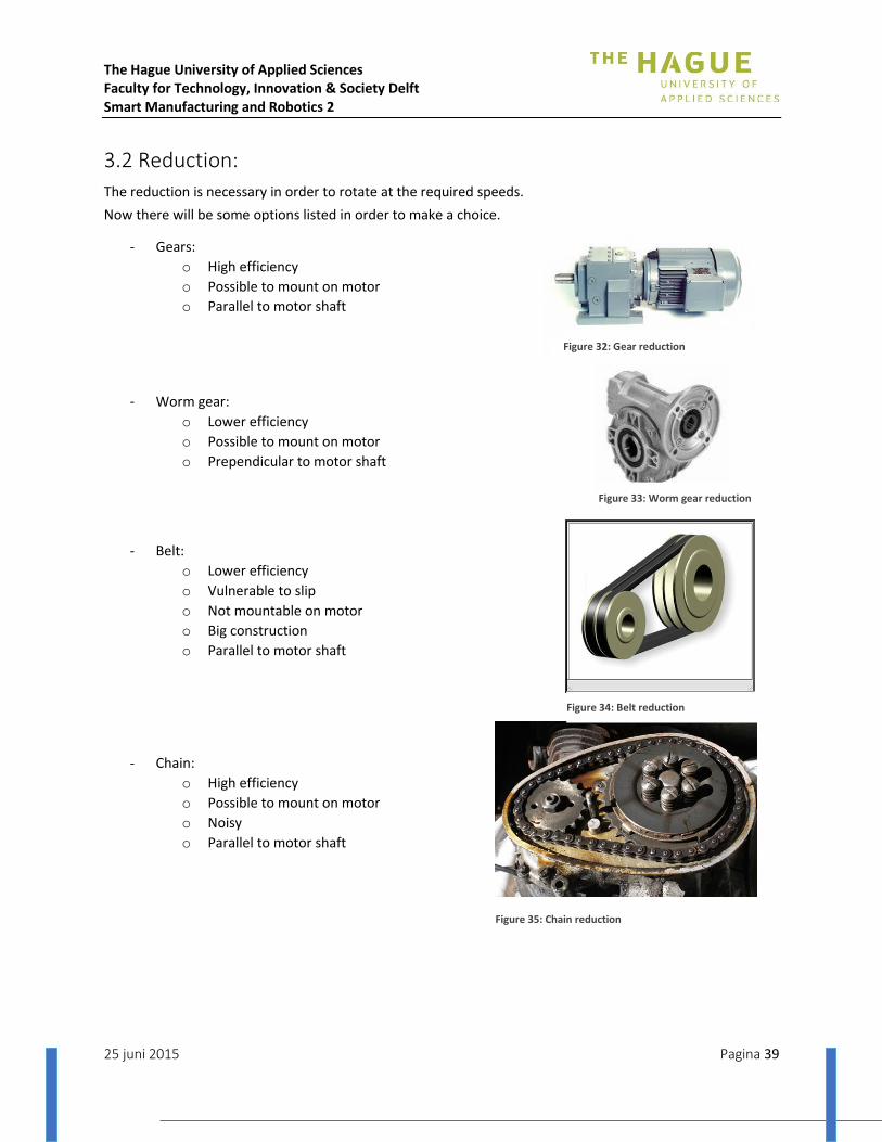
The Hague University of Applied Sciences Faculty for Technology, Innovation & Society Delft Smart Manufacturing and Robotics 2
25 juni 2015 Pagina 39
3.2 Reduction:
The reduction is necessary in order to rotate at the required speeds.
Now there will be some options listed in order to make a choice.
- Gears:
o High efficiency
o Possible to mount on motor
o Parallel to motor shaft
- Worm gear:
o Lower efficiency
o Possible to mount on motor
o Prependicular to motor shaft
- Belt:
o Lower efficiency
o Vulnerable to slip
o Not mountable on motor
o Big construction
o Parallel to motor shaft
- Chain:
o High efficiency
o Possible to mount on motor
o Noisy
o Parallel to motor shaft
Figure 35: Chain reduction
Figure 32: Gear reduction
Figure 33: Worm gear reduction
Figure 34: Belt reduction
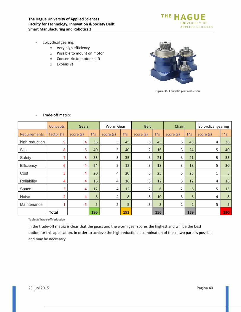
The Hague University of Applied Sciences Faculty for Technology, Innovation & Society Delft Smart Manufacturing and Robotics 2
25 juni 2015 Pagina 40
- Epicyclical gearing:
o Very high efficiency
o Possible to mount on motor
o Concentric to motor shaft
o Expensive
- Trade-off matrix:
Concepts Gears Worm Gear Belt Chain Epicyclical gearing
Requirements factor (f) score (s) f*s score (s) f*s score (s) f*s score (s) f*s score (s) f*s
high reduction 9 4 36 5 45 5 45 5 45 4 36
Slip 8 5 40 5 40 2 16 3 24 5 40
Safety 7 5 35 5 35 3 21 3 21 5 35
Efficiency 6 4 24 2 12 3 18 3 18 5 30
Cost 5 4 20 4 20 5 25 5 25 1 5
Reliability 4 4 16 4 16 3 12 3 12 4 16
Space 3 4 12 4 12 2 6 2 6 5 15
Noise 2 4 8 4 8 5 10 3 6 4 8
Maintenance 1 5 5 5 5 3 3 2 2 5 5
Total 196 193 156 159 190
Table 3: Trade-off reduction
In the trade-off matrix is clear that the gears and the worm gear scores the highest and will be the best
option for this application. In order to achieve the high reduction a combination of these two parts is possible
and may be necessary.
Figure 36: Epicyclic gear reduction
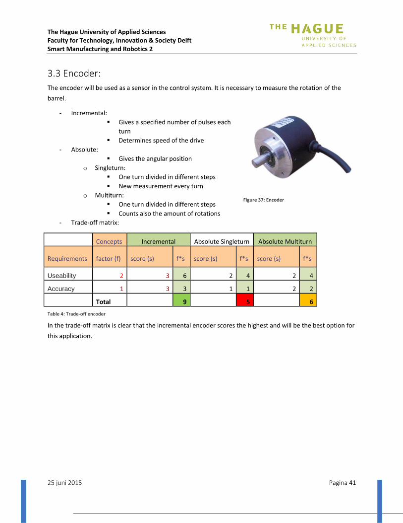
The Hague University of Applied Sciences Faculty for Technology, Innovation & Society Delft Smart Manufacturing and Robotics 2
25 juni 2015 Pagina 41
3.3 Encoder:
The encoder will be used as a sensor in the control system. It is necessary to measure the rotation of the
barrel.
- Incremental:
Gives a specified number of pulses each
turn
Determines speed of the drive
- Absolute:
Gives the angular position
o Singleturn:
One turn divided in different steps
New measurement every turn
o Multiturn:
One turn divided in different steps
Counts also the amount of rotations
- Trade-off matrix:
Concepts Incremental Absolute Singleturn Absolute Multiturn
Requirements factor (f) score (s) f*s score (s) f*s score (s) f*s
Useability 2 3 6 2 4 2 4
Accuracy 1 3 3 1 1 2 2
Total 9 5 6
Table 4: Trade-off encoder
In the trade-off matrix is clear that the incremental encoder scores the highest and will be the best option for
this application.
Figure 37: Encoder

The Hague University of Applied Sciences Faculty for Technology, Innovation & Society Delft Smart Manufacturing and Robotics 2
25 juni 2015 Pagina 42
3.4 Control:
In a control system there needs to be a unit which can control
the engine and can communicate with other subsystems.
Below are some options listed which are possible for the motor
control.
- Frequency converter:
o Can change the speed of the motor
o Variable voltage input for speed setting
o Easy to use with AC motor
o Easy to program and control
o Usable in a control system
- Softstarter:
o Can control the start-up of the engine
o Not able to control the rotation speed of the
motor in a control system
- Trade-off matrix:
Concepts Frequency converter Softstarter
Requirements factor (f) score (s) f*s score (s) f*s
Cost 2 2 4 0 0
Controlling 1 2 2 1 1
Total 6 1
Table 5: Trade-off control
In the trade-off matrix is clear that the frequency converter scores the highest and will be the best option for
this application.
Figure 38: Frequency converter
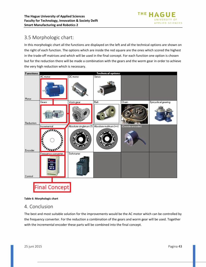
The Hague University of Applied Sciences Faculty for Technology, Innovation & Society Delft Smart Manufacturing and Robotics 2
25 juni 2015 Pagina 43
3.5 Morphologic chart:
In this morphologic chart all the functions are displayed on the left and all the technical options are shown on
the right of each function. The options which are inside the red square are the ones which scored the highest
in the trade-off matrices and which will be used in the final concept. For each function one option is chosen
but for the reduction there will be made a combination with the gears and the worm gear in order to achieve
the very high reduction which is necessary.
Table 6: Morphologic chart
4. Conclusion
The best and most suitable solution for the improvements would be the AC motor which can be controlled by
the frequency converter. For the reduction a combination of the gears and worm gear will be used. Together
with the incremental encoder these parts will be combined into the final concept.

The Hague University of Applied Sciences Faculty for Technology, Innovation & Society Delft Smart Manufacturing and Robotics 2
25 juni 2015 Pagina 44
Appendix III: Manipulator peripherals
1. Calculations motor
For the propulsion of the barrel there is a need for a motor. In the next calculations some parameters will be
calculated concerning the rotation of the pressure vessel. At first several reductions will be calculated based
on the requirements of the application. The reductions are dependent on the different rotation speeds
possible of motors. In the second part the torque and the motor power will be calculated based on the
properties of the pressure vessel and the tape feed of the application. These calculations will be used to
make a proper decision for the reduction and the motor. Because there are some uncertainties about the
final pressure vessel, this calculations will be based on the barrel that will be used in the final demonstration.
Facts - Diameter barrel: 𝐷 = 254 𝑚𝑚
- Radius outside barrel: 𝑅 = 127 𝑚𝑚 = 0,127 𝑚
- Radius inside barrel: 𝑟 = 123 𝑚𝑚 = 0,123 𝑚
- Tape feed speed: vt = 1 𝑚/𝑚𝑖𝑛
- Distance of one revolution: 𝑥 = 120 𝑐𝑚
- Time for one revolution: 𝑡 =Distance of one revolution
𝑇𝑎𝑝𝑒 𝑓𝑒𝑒𝑑 𝑠𝑝𝑒𝑒𝑑=
120 𝑐𝑚
100 𝑐𝑚/𝑚𝑖𝑛= 1,2 𝑚𝑖𝑛 = 72 𝑠𝑒𝑐
- Average motor revolutions: 𝑛 = 𝑇𝑎𝑝𝑒 𝑓𝑒𝑒𝑑 𝑠𝑝𝑒𝑒𝑑
𝐷𝑖𝑠𝑡𝑎𝑛𝑐𝑒 𝑜𝑓 𝑜𝑛𝑒 𝑟𝑒𝑣𝑜𝑙𝑢𝑡𝑖𝑜𝑛=
100 𝑐𝑚/𝑚𝑖𝑛
120 𝑐𝑚= 0,83 𝑟𝑝𝑚
- Angular velocity: 𝜔 = 2𝜋
72= 0,087 𝑟𝑎𝑑/𝑠
- Density barrel: 𝜌 = 946 𝑘𝑔/𝑚³ (Polypropylene)
- Volume barrel: 𝑉 = 0,00183 𝑚³
- Mass barrel: 𝑚 = 1,73 𝑘𝑔
Assumptions
● 𝐹𝑡 = 50𝑁
● Acceleration time: 𝑎 = 0,1 𝑚/𝑠2
Table 7: Magnitudes and units
Name Magnitude Unit
Tape force Ft N
Motor torque Mm Nm
Reduction ratio i
Angular velocity ω rad/s
Efficiency η
Inside radius r1 m
Outside radius r2 m

The Hague University of Applied Sciences Faculty for Technology, Innovation & Society Delft Smart Manufacturing and Robotics 2
25 juni 2015 Pagina 45
Density ρ Kg/m³
Power P W
Inertia I Kgm²
Angular acceleration α rad/s²
Reduction
An asynchronous motor has a fixed synchronized rotation speed related to the poles inside the motor. An 8
pole motor has the lowest speed so this is the motor which fits the most for this application. However, a
motor with 8 poles is rare to find and will not be recommended. In the setup we will use a frequency
converter in order to be able to control the speed of the motor by changing the frequency.
The motor is preferred not to be used under 15Hz because it can get too hot and be damaged. The most
preferable frequencies of a motor are 40-60Hz. Therefore the standard set point of the motor must be inside
this frequency window. The reduction needed for the motor will be calculated with the condition of keeping
the set point inside the window.
Until this point it is not certain which motor will be used for the application so the reduction calculation will
be conducted for all the different speeds available.
Table 8: Motor poles
poles pole-pairs
n sync (rpm)
2 1 3000
4 2 1500
6 3 1000
8 4 750
Assumptions: The motor needs to go faster when the tape is applied on the poles and needs to go slower
when the tape is applied on the middle of the barrel to keep the tape feed speed constant. As an assumption
of the average rotation speed we will use 1 rpm for the calculations of the reduction. The variations in speed
will be realized with the use of the frequency converter in the control system.
- Reduction at 750 rpm (motor with 8 poles):
f = 50 Hz: 𝑛 = 750 𝑟𝑝𝑚
f = 60 Hz: 𝑛 = 750 𝑟𝑝𝑚 ∗60 𝐻𝑧
50 𝐻𝑧= 750 𝑟𝑝𝑚 ∗ 1,2 = 900 𝑟𝑝𝑚
f = 40 Hz: 𝑛 = 750 𝑟𝑝𝑚 ∗40 𝐻𝑧
50 𝐻𝑧= 750 𝑟𝑝𝑚 ∗ 0,8 = 600 𝑟𝑝𝑚
Reduction: 𝑖 = 1
600= 0,00167

The Hague University of Applied Sciences Faculty for Technology, Innovation & Society Delft Smart Manufacturing and Robotics 2
25 juni 2015 Pagina 46
- Reduction at 1000 rpm (motor with 6 poles):
f = 50 Hz: 𝑛 = 1000 𝑟𝑝𝑚
f = 60 Hz: 𝑛 = 1000 𝑟𝑝𝑚 ∗60 𝐻𝑧
50 𝐻𝑧= 1000 𝑟𝑝𝑚 ∗ 1,2 = 1200 𝑟𝑝𝑚
f = 40 Hz: 𝑛 = 1000 𝑟𝑝𝑚 ∗40 𝐻𝑧
50 𝐻𝑧= 1000 𝑟𝑝𝑚 ∗ 0,8 = 800 𝑟𝑝𝑚
Reduction: 𝑖 = 1
800= 0,00125
- Reduction at 1500 rpm (motor with 4 poles):
f = 50 Hz: 𝑛 = 1500 𝑟𝑝𝑚
f = 60 Hz: 𝑛 = 1500 𝑟𝑝𝑚 ∗60 𝐻𝑧
50 𝐻𝑧= 1500 𝑟𝑝𝑚 ∗ 1,2 = 1800 𝑟𝑝𝑚
f = 40 Hz: 𝑛 = 1500 𝑟𝑝𝑚 ∗40 𝐻𝑧
50 𝐻𝑧= 1500 𝑟𝑝𝑚 ∗ 0,8 = 1200 𝑟𝑝𝑚
Reduction: 𝑖 = 1
1200= 0,00083
- Reduction at 750 rpm (motor with 2 poles):
f = 50 Hz: 𝑛 = 3000 𝑟𝑝𝑚
f = 60 Hz: 𝑛 = 3000 𝑟𝑝𝑚 ∗60 𝐻𝑧
50 𝐻𝑧= 3000 𝑟𝑝𝑚 ∗ 1,2 = 3600 𝑟𝑝𝑚
f = 40 Hz: 𝑛 = 3000 𝑟𝑝𝑚 ∗40 𝐻𝑧
50 𝐻𝑧= 3000 𝑟𝑝𝑚 ∗ 0,8 = 2400 𝑟𝑝𝑚
Reduction: 𝑖 = 1
2400= 0,0004167

The Hague University of Applied Sciences Faculty for Technology, Innovation & Society Delft Smart Manufacturing and Robotics 2
25 juni 2015 Pagina 47
Power
Torque: 𝑇 = 𝑙𝑜𝑎𝑑 + 𝑖𝑛𝑒𝑟𝑡𝑖𝑎 ∗ 𝑎𝑛𝑔𝑢𝑙𝑎𝑟 𝑎𝑐𝑐𝑒𝑙𝑒𝑟𝑎𝑡𝑖𝑜𝑛
Load: TL = 𝐹 ∗ 𝑟 = 50𝑁 ∗ 0,127𝑚 = 6,35 𝑁𝑚
Inertia: 𝐼 = 1
2 ∗ 𝑚 ∗ (𝑟2² + 𝑟1²) = 0,027 𝑘𝑔𝑚²
Angular acceleration: 𝛼 = 𝜔
𝑡 =
2𝜋∗4
60
0,1 =
0,42
0,1 = 4,2 𝑟𝑎𝑑/𝑠²
Torque: 𝑀𝑚 = 𝐼𝑣𝑎𝑡 ∗ 𝛼 + 𝐹𝑡 ∗ 𝑟 = 0,027 𝑘𝑔𝑚² ∗ 4,2 𝑟𝑎𝑑/𝑠² + 50𝑁 ∗ 0,127𝑚 = 6,46 𝑁𝑚
Power: 𝑃 = 𝑀 ∗ 𝜔 = 6,46 ∗ 2 𝜋 ∗ 4
60= 2,7 𝑊𝑎𝑡𝑡
Conclusion
The motor which will be chosen needs to be discussed with the supplier of the motor in order to know the
exact specifications of the motor.
Based on this calculations the most suitable solution will be to choose an available motor with an angular
velocity as low as possible. In that case the reduction will be the lowest too. The calculated motor power
needed to power this setup is 2,7 Watt. This is a very low required power so the motor can be low on power.
Almost every industrial motor is strong enough to power this application.
Figure 39: Schematic rod forces

The Hague University of Applied Sciences Faculty for Technology, Innovation & Society Delft Smart Manufacturing and Robotics 2
25 juni 2015 Pagina 48
2. Calculations encoder
In this setup we will use an encoder to detect in which position the barrel is in the time. With this information
the control system can adapt on the speed of the robot and the rotation of the barrel.
This calculation is based on the assumption of an encoder which gives 360 pulses in one rotation. The
calculations can be easily adapted if the specifications of the encoder would change. Because the rotation of
the pressure vessel and the tape feed is not constant throughout one rotation, this calculation will be based
on the maximum values. The maximum rotation speed and a tape feed of 90° on the pressure vessel will be
used in this calculation.
360 𝑝𝑢𝑙𝑠𝑒𝑠/𝑟𝑜𝑡𝑎𝑡𝑖𝑜𝑛
1° = 1
360𝐶 (𝐶 = 𝑜𝑢𝑡𝑙𝑖𝑛𝑒 𝑜𝑓 𝑡ℎ𝑒 𝑏𝑎𝑟𝑟𝑒𝑙)
𝐷 = 10 𝑖𝑛𝑐ℎ 𝐷 = 10 ∗ 2,54 𝐷 = 25,4 𝑐𝑚 𝐷 = 254 𝑚𝑚 (𝐷 = 𝐷𝑖𝑎𝑚𝑒𝑡𝑒𝑟 𝑏𝑎𝑟𝑟𝑒𝑙)
𝐶 = 𝜋 ∗ 𝐷 = 804 𝑚𝑚
𝐷𝑖𝑠𝑡𝑎𝑛𝑐𝑒 𝑓𝑜𝑟 𝑜𝑛𝑒 𝑠𝑡𝑒𝑝: 𝐶
𝐷𝑒𝑔𝑟𝑒𝑒𝑠=
804 𝑚𝑚
360 ° = 2,2 𝑚𝑚
𝑇𝑎𝑝𝑒 𝑓𝑒𝑒𝑑: 1𝑚
𝑚𝑖𝑛
1000 𝑚𝑚
60 𝑠 16,6 𝑚𝑚/𝑠
𝑆𝑡𝑒𝑝𝑠 𝑠𝑒𝑐𝑜𝑛𝑑⁄ :
𝑚𝑚𝑠𝐶
𝐷𝑒𝑔𝑟𝑒𝑒𝑠
= 16,6 𝑚𝑚/𝑠
2,2 𝑚𝑚= 7,57 𝑠𝑡𝑒𝑝𝑠/𝑠𝑒𝑐𝑜𝑛𝑑
Conclusion
If the encoder will have 360 pulses in one rotation the accuracy of the encoder will be sufficient for the
application. If the encoder would give more pulses the accuracy will be increased and this will be for the
better for the application. If the encoder would give less than 360 pulses there will need to be a recalculation
in order to see if the encoder is accurate enough for the application.

The Hague University of Applied Sciences Faculty for Technology, Innovation & Society Delft Smart Manufacturing and Robotics 2
25 juni 2015 Pagina 49
3. Rotating system setup
In this chapter the setup of the rotating system will be described. It will handle all the electrical parts in the
setup and the connections between them. This will be divided into two pieces. At first the current setup at
the beginning of the project is described. This will contain of the electric parts, their relations and their
settings. In the second part, the new setup will be described by the electric parts, their relations and
communication, their settings and at the testing of the frequency converter.
3.1 Current setup
In the current setup, every electric part made by previous groups will be discussed. This setup will be the
start of this project.
3.1.1 Electric scheme rotator This chapter is the information of the electronic components is given and how they are connected.
Figure 40: Electric scheme current situation
To connect the frequency converter to the robot-controller 4 pins from the robot controller are needed. Two
pins are needed to determine the rotation way of the motor. If voltage is put on pin 3 of the frequency
converter, the motor will turn left. If voltage is put on pin 4 of the frequency converter, the motor will turn
right. If there is voltage on both pin 3 and 4 the motor will not turn. We need 24V from the robot controller
for the emergency stop which is connected to pin 6 of the frequency converter. The emergency stop is a
normally closed connection, so if the emergency stop is pushed the frequency converter get a signal on pin 6
and the motor stops turning. Pin 10 of the frequency converter is connected to the Ground of the robot
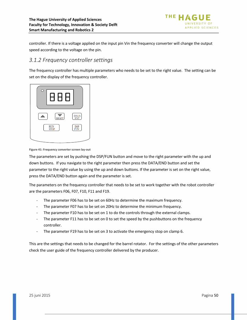
The Hague University of Applied Sciences Faculty for Technology, Innovation & Society Delft Smart Manufacturing and Robotics 2
25 juni 2015 Pagina 50
controller. If there is a voltage applied on the input pin Vin the frequency converter will change the output
speed according to the voltage on the pin.
3.1.2 Frequency controller settings
The frequency controller has multiple parameters who needs to be set to the right value. The setting can be
set on the display of the frequency controller.
Figure 41: Frequency converter screen lay-out
The parameters are set by pushing the DSP/FUN button and move to the right parameter with the up and
down buttons. If you navigate to the right parameter then press the DATA/END button and set the
parameter to the right value by using the up and down buttons. If the parameter is set on the right value,
press the DATA/END button again and the parameter is set.
The parameters on the frequency controller that needs to be set to work together with the robot controller
are the parameters F06, F07, F10, F11 and F19.
- The parameter F06 has to be set on 60Hz to determine the maximum frequency.
- The parameter F07 has to be set on 20Hz to determine the minimum frequency.
- The parameter F10 has to be set on 1 to do the controls through the external clamps.
- The parameter F11 has to be set on 0 to set the speed by the pushbuttons on the frequency
controller.
- The parameter F19 has to be set on 3 to activate the emergency stop on clamp 6.
This are the settings that needs to be changed for the barrel rotator. For the settings of the other parameters
check the user guide of the frequency controller delivered by the producer.
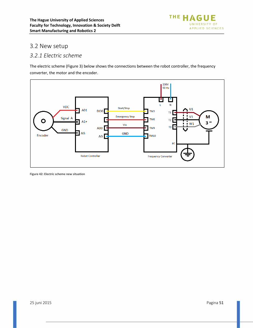
The Hague University of Applied Sciences Faculty for Technology, Innovation & Society Delft Smart Manufacturing and Robotics 2
25 juni 2015 Pagina 51
3.2 New setup
3.2.1 Electric scheme
The electric scheme (Figure 3) below shows the connections between the robot controller, the frequency
converter, the motor and the encoder.
Figure 42: Electric scheme new situation

The Hague University of Applied Sciences Faculty for Technology, Innovation & Society Delft Smart Manufacturing and Robotics 2
25 juni 2015 Pagina 52
3.2.2 Frequency controller settings
To program the frequency controller in the right way for the application there are some functions which are
needed to be set. For this application we want the maximum frequency of the converter at 60Hz and the
minimum at 20Hz-30Hz (depending on the required minimum rotation speed). Next it needs to be able to
control the on/off mode of the frequency converter by a signal from the robot controller. There is also a need
for an emergency stop. The robot controller has a function for an emergency stop and will stop the frequency
controller too if the emergency button is pressed from the robot. At last the frequency itself needs to be
controlled from the robot controller. To make this happen there are some functions to be set good.
To be able to control the start/stop of the frequency converter, the following functions are needed to be
altered:
F03 needs to be set on 1
F10 needs to be set on 1
To be able to operate the emergency button from the robot for the frequency converter too, the following
functions are needed to be altered:
F19 needs to be set on 3
To be able to control the frequency by using the robot controller, the following functions are needed to be
altered:
F11 needs to be set on 1
In the table below (Table 1) there are all the functions described with the factory setting and with the
adapted settings for this application.
Table 9: Frequency converter functions
Description Function Setting Factory Setting Explanation
Acceleration time 1 0,1 5.0
Deceleration time 2 0,1 5.0
Operation mode
3 1 0 0 = Forward/Stop , Reverse/Stop 1 = Run/Stop , Forward/Reverse (TM3)
Motor direction 4 0 0
0 = Forward 1 = Reverse
V/F Pattern 5 1 1
Frequency upper limit 6 60 Hz 50/60 Hz
Frequency lower limit 7 15 Hz 0.0 Hz
SP1 Frequency 8 10 Hz 10 Hz Frequency bij SP1 input
JOG frequency 9 6 Hz 6 Hz
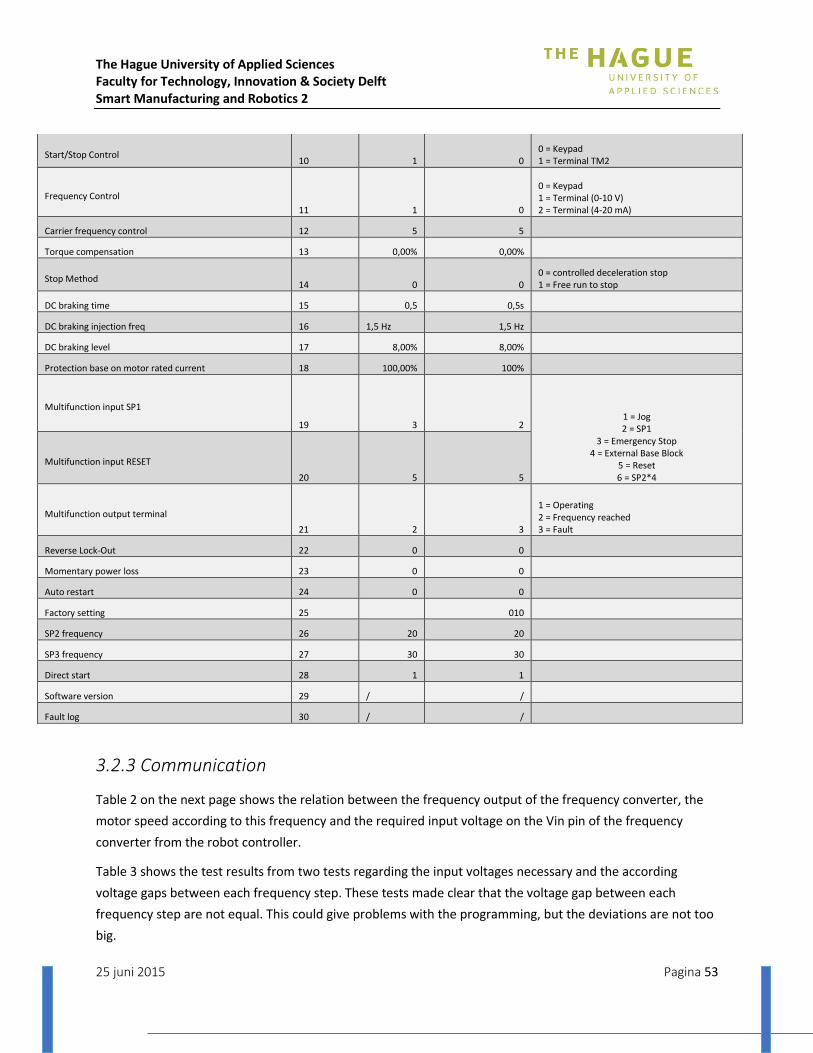
The Hague University of Applied Sciences Faculty for Technology, Innovation & Society Delft Smart Manufacturing and Robotics 2
25 juni 2015 Pagina 53
Start/Stop Control 10 1 0
0 = Keypad 1 = Terminal TM2
Frequency Control
11 1 0
0 = Keypad 1 = Terminal (0-10 V) 2 = Terminal (4-20 mA)
Carrier frequency control 12 5 5
Torque compensation 13 0,00% 0,00%
Stop Method 14 0 0
0 = controlled deceleration stop 1 = Free run to stop
DC braking time 15 0,5 0,5s
DC braking injection freq 16 1,5 Hz 1,5 Hz
DC braking level 17 8,00% 8,00%
Protection base on motor rated current 18 100,00% 100%
Multifunction input SP1
19 3 2 1 = Jog 2 = SP1
3 = Emergency Stop 4 = External Base Block
5 = Reset 6 = SP2*4
Multifunction input RESET
20 5 5
Multifunction output terminal
21 2 3
1 = Operating 2 = Frequency reached 3 = Fault
Reverse Lock-Out 22 0 0
Momentary power loss 23 0 0
Auto restart 24 0 0
Factory setting 25 010
SP2 frequency 26 20 20
SP3 frequency 27 30 30
Direct start 28 1 1
Software version 29 / /
Fault log 30 / /
3.2.3 Communication
Table 2 on the next page shows the relation between the frequency output of the frequency converter, the
motor speed according to this frequency and the required input voltage on the Vin pin of the frequency
converter from the robot controller.
Table 3 shows the test results from two tests regarding the input voltages necessary and the according
voltage gaps between each frequency step. These tests made clear that the voltage gap between each
frequency step are not equal. This could give problems with the programming, but the deviations are not too
big.
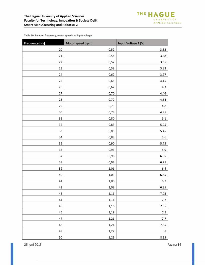
The Hague University of Applied Sciences Faculty for Technology, Innovation & Society Delft Smart Manufacturing and Robotics 2
25 juni 2015 Pagina 54
Table 10: Relation frequency, motor speed and input voltage
Frequency [Hz] Motor speed [rpm] Input Voltage 1 [V]
20 0,52 3,32
21 0,54 3,48
22 0,57 3,65
23 0,59 3,83
24 0,62 3,97
25 0,65 4,15
26 0,67 4,3
27 0,70 4,46
28 0,72 4,64
29 0,75 4,8
30 0,78 4,95
31 0,80 5,1
32 0,83 5,25
33 0,85 5,45
34 0,88 5,6
35 0,90 5,75
36 0,93 5,9
37 0,96 6,05
38 0,98 6,25
39 1,01 6,4
40 1,03 6,55
41 1,06 6,7
42 1,09 6,85
43 1,11 7,03
44 1,14 7,2
45 1,16 7,35
46 1,19 7,5
47 1,21 7,7
48 1,24 7,85
49 1,27 8
50 1,29 8,15
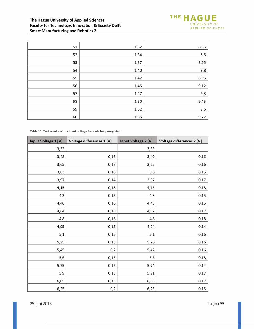
The Hague University of Applied Sciences Faculty for Technology, Innovation & Society Delft Smart Manufacturing and Robotics 2
25 juni 2015 Pagina 55
51 1,32 8,35
52 1,34 8,5
53 1,37 8,65
54 1,40 8,8
55 1,42 8,95
56 1,45 9,12
57 1,47 9,3
58 1,50 9,45
59 1,52 9,6
60 1,55 9,77
Table 11: Test results of the input voltage for each frequency step
Input Voltage 1 [V] Voltage differences 1 [V] Input Voltage 2 [V] Voltage differences 2 [V]
3,32 3,33
3,48 0,16 3,49 0,16
3,65 0,17 3,65 0,16
3,83 0,18 3,8 0,15
3,97 0,14 3,97 0,17
4,15 0,18 4,15 0,18
4,3 0,15 4,3 0,15
4,46 0,16 4,45 0,15
4,64 0,18 4,62 0,17
4,8 0,16 4,8 0,18
4,95 0,15 4,94 0,14
5,1 0,15 5,1 0,16
5,25 0,15 5,26 0,16
5,45 0,2 5,42 0,16
5,6 0,15 5,6 0,18
5,75 0,15 5,74 0,14
5,9 0,15 5,91 0,17
6,05 0,15 6,08 0,17
6,25 0,2 6,23 0,15
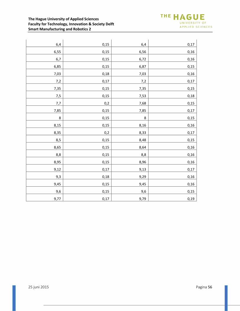
The Hague University of Applied Sciences Faculty for Technology, Innovation & Society Delft Smart Manufacturing and Robotics 2
25 juni 2015 Pagina 56
6,4 0,15 6,4 0,17
6,55 0,15 6,56 0,16
6,7 0,15 6,72 0,16
6,85 0,15 6,87 0,15
7,03 0,18 7,03 0,16
7,2 0,17 7,2 0,17
7,35 0,15 7,35 0,15
7,5 0,15 7,53 0,18
7,7 0,2 7,68 0,15
7,85 0,15 7,85 0,17
8 0,15 8 0,15
8,15 0,15 8,16 0,16
8,35 0,2 8,33 0,17
8,5 0,15 8,48 0,15
8,65 0,15 8,64 0,16
8,8 0,15 8,8 0,16
8,95 0,15 8,96 0,16
9,12 0,17 9,13 0,17
9,3 0,18 9,29 0,16
9,45 0,15 9,45 0,16
9,6 0,15 9,6 0,15
9,77 0,17 9,79 0,19

The Hague University of Applied Sciences Faculty for Technology, Innovation & Society Delft Smart Manufacturing and Robotics 2
25 juni 2015 Pagina 57
Figure 43: Driveshaft drawing
Appendix IV: Final manipulator specifications
1. Driveshaft
The driveshaft which will transfer the rotation of the motor onto the vessel is custom made for this
application. The drawing below shows the dimensions of the driveshaft. The diameter of the driveshaft which
will go inside the reduction of the motor is 25mm.

The Hague University of Applied Sciences Faculty for Technology, Innovation & Society Delft Smart Manufacturing and Robotics 2
25 juni 2015 Pagina 58
2. Bearings To support the shaft which will transfer the rotation of the engine onto the barrel, two tapped based pillow
blocks ‘UCPA 205’ bearings will be used. The picture below shows the bearings and the driveshaft used in this
application.
3. Motor
The motor used for the rotation of the barrel is a 0,09 kW, M-series (M56b4) from Carpanelli, three phase
motor provided by ‘MAK aandrijvingen’. The motor has a rotation speed of 1360 rpm. The picture below
shows the specifications of the motor.
Figure 44: Final bearings
Figure 45: Final motor
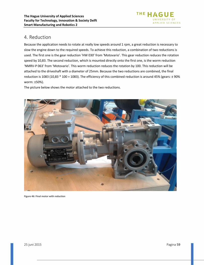
The Hague University of Applied Sciences Faculty for Technology, Innovation & Society Delft Smart Manufacturing and Robotics 2
25 juni 2015 Pagina 59
4. Reduction
Because the application needs to rotate at really low speeds around 1 rpm, a great reduction is necessary to
slow the engine down to the required speeds. To achieve this reduction, a combination of two reductions is
used. The first one is the gear reduction ‘HW 030’ from ‘Motovario’. This gear reduction reduces the rotation
speed by 10,83. The second reduction, which is mounted directly onto the first one, is the worm reduction
‘NMRV-P 063’ from ‘Motovario’. This worm reduction reduces the rotation by 100. This reduction will be
attached to the driveshaft with a diameter of 25mm. Because the two reductions are combined, the final
reduction is 1083 (10,83 * 100 = 1083). The efficiency of this combined reduction is around 45% (gears: ± 90%
worm: ±50%).
The picture below shows the motor attached to the two reductions.
Figure 46: Final motor with reduction

The Hague University of Applied Sciences Faculty for Technology, Innovation & Society Delft Smart Manufacturing and Robotics 2
25 juni 2015 Pagina 60
5. Encoder
In order to control the system properly, there is a need to know at which speed or at which position the
barrel is. Therefor an encoder on the driveshaft is used. The encoder used is an incremental shaft encoder
type RI 32 from ‘Hengstler’. This encoder has a pulse count of 360 pulses. According to the calculations in the
annex this is sufficient for this application.
6. Frequency converter
To control the motor, the frequency converter ‘E2-201-H1F’ from ’T-Verter’ will be used. The reach of the
frequency converter is from 1Hz till 200Hz. The frequency converter can be set manually or by means of a
variable input voltage on a input on the frequency controller. For this application we will use a variable input
voltage from the robot controller to alter the speed of the motor through the frequency converter. The
maximum rotation speed of the motor is 60Hz. Because the maximum rotation speed of the motor is 60Hz
the maximum frequency of the frequency controller has to be set to 60Hz.

The Hague University of Applied Sciences Faculty for Technology, Innovation & Society Delft Smart Manufacturing and Robotics 2
25 juni 2015 Pagina 61
Appendix V: EOAT Redesign
FACULTY FOR TECHNOLOGY, INNOVATI ON & SOC IETY
REPORT REDESIGN END OF ARM TOOL
Name: Dirk van Trigt
Course: SMR2 - Project
Period: April 2015 – July 2015
Tutor: Ir. T. Brilleman

The Hague University of Applied Sciences Faculty for Technology, Innovation & Society Delft Smart Manufacturing and Robotics 2
25 juni 2015 Pagina 62
Content 1 Introduction ................................................................................................................................................ 63
2 Theory ......................................................................................................................................................... 64
3 Design and development ............................................................................................................................ 65
3.1 Prelude ............................................................................................................................................... 65
3.2 First redesign ...................................................................................................................................... 66
3.3 Final design......................................................................................................................................... 68
3.4 Development ...................................................................................................................................... 69
4 Result .......................................................................................................................................................... 70
5 Appendices .................................................................................................... Error! Bookmark not defined.

The Hague University of Applied Sciences Faculty for Technology, Innovation & Society Delft Smart Manufacturing and Robotics 2
25 juni 2015 Pagina 63
1 Introduction
The main goal of this project is to wrap polypropylene glass fibre reinforced filament around a pressure
vessel. One of the most important tools to establish this is the End Of Arm Tool (EOAT). In this report explains
how the EOAT is designed and developed.
The Hague University of Applied Sciences Faculty for Technology, Innovation & Society Delft Smart Manufacturing and Robotics 2
25 juni 2015 Pagina 64
2 Theory
The End Of Arm Tool consists of a milled block of aluminium that encloses a heating element. This heating
element generates heat and conducts this heat through the aluminium block to the filament that is pulled
through a narrow opening in the aluminium block. While the filament is pulled through the polypropylene
reaches a viscose state which is necessary to make the filament stick to the pressure vessel or the previous
layer of filament.
The aluminium block could directly be mounted to the robot arm, but for the following reasons this is not the
most efficient way of using the heating element:
- Heat loss, therefore loss of energy that should be used to heat up the filament;
- Heats up the robot, which causes a shutdown when it reaches a certain temperature;
- Difficult to mount on the robot
- No ability to service the heating element after use because it will be too hot to handle.

The Hague University of Applied Sciences Faculty for Technology, Innovation & Society Delft Smart Manufacturing and Robotics 2
25 juni 2015 Pagina 65
3 Design and development
3.1 Prelude The previous project group developed a EOAT consisting 30 cm aluminum tubing, plaster wall plating
wrapped in aluminum foil, aluminum plating on which the heating elements were mounted. Between the
aluminum tubing and the plaster wall plating was glass wool to insulate that little bit extra (see Figure 47).
They developed this for a filament with different dimensions, so a new EOAT had to be created.
Figure 47:The EOAT design of the previous project group
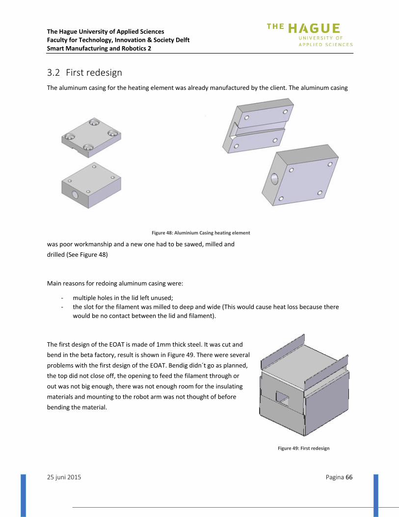
The Hague University of Applied Sciences Faculty for Technology, Innovation & Society Delft Smart Manufacturing and Robotics 2
25 juni 2015 Pagina 66
3.2 First redesign
The aluminum casing for the heating element was already manufactured by the client. The aluminum casing
was poor workmanship and a new one had to be sawed, milled and
drilled (See Figure 48)
Main reasons for redoing aluminum casing were:
- multiple holes in the lid left unused;
- the slot for the filament was milled to deep and wide (This would cause heat loss because there
would be no contact between the lid and filament).
The first design of the EOAT is made of 1mm thick steel. It was cut and
bend in the beta factory, result is shown in Figure 49. There were several
problems with the first design of the EOAT. Bendig didn´t go as planned,
the top did not close off, the opening to feed the filament through or
out was not big enough, there was not enough room for the insulating
materials and mounting to the robot arm was not thought of before
bending the material.
Figure 48: Aluminium Casing heating element
Figure 49: First redesign
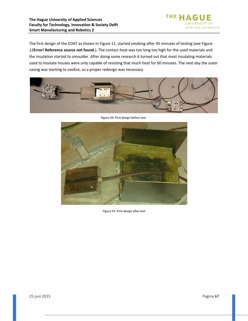
The Hague University of Applied Sciences Faculty for Technology, Innovation & Society Delft Smart Manufacturing and Robotics 2
25 juni 2015 Pagina 67
The first design of the EOAT as shown in Figure 11, started smoking after 45 minutes of testing (see Figure
12Error! Reference source not found.). The contact heat was too long too high for the used materials and
the insulation started to smoulder .After doing some research it turned out that most insulating materials
used to insulate houses were only capable of resisting that much heat for 60 minutes. The next day the outer
casing was starting to oxidize, so a proper redesign was necessary.
Figure 50: First design before test
Figure 51: First design after test
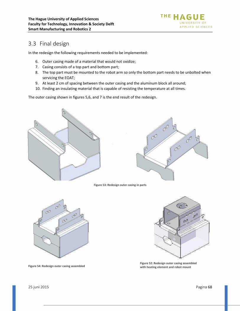
The Hague University of Applied Sciences Faculty for Technology, Innovation & Society Delft Smart Manufacturing and Robotics 2
25 juni 2015 Pagina 68
3.3 Final design
In the redesign the following requirements needed to be implemented:
6. Outer casing made of a material that would not oxidize;
7. Casing consists of a top part and bottom part;
8. The top part must be mounted to the robot arm so only the bottom part needs to be unbolted when
servicing the EOAT;
9. At least 2 cm of spacing between the outer casing and the aluminum block all around;
10. Finding an insulating material that is capable of resisting the temperature at all times.
The outer casing shown in figures 5,6, and 7 is the end result of the redesign.
Figure 53: Redesign outer casing in parts
Figure 54: Redesign outer casing assembled Figure 52: Redesign outer casing assembled with heating element and robot mount
The Hague University of Applied Sciences Faculty for Technology, Innovation & Society Delft Smart Manufacturing and Robotics 2
25 juni 2015 Pagina 69
The material choice for the outer casing was not as difficult. Steel and stainless steel both oxidize when they
are submitted to high temperatures. Except for AISI310 which is a stainless steel made for these temperature
changes. This material was unavailable in time span for the development of the EOAT. The next best choice
was either titanium or a type of aluminum. Since titanium is too expensive and also unavailable in the time
span, the choice for aluminum was the best option. The choice was AlMg3, this was available and good for
welding and braking.
To inquire more information about insulating materials several hardware stores were visited and asked the
question if they had a material that could withstand the heat generated by the heating element. All of them
confirmed the previous found out facts that all insulating materials for the construction of houses would not
withstand the heat for longer than 60 minutes before losing their insulating capabilities and degrading. Their
advice was to visit a hearth salesman or builder.
At the hearth salesman good advice was acquired which resulted into a gift of a board of Super Isol. The
hearth salesman used it to stick it between the wooden walls and the stone tiles in a fireplace. Stone tiles do
not insulate at all which means the board of Super Isol prevents the wood from getting hot or burning. The
specifications of this material are in the appendices.
3.4 Development
The aluminum casing was cut by a laser at a company in Haarlem. The cut sheet metal was bend by a press
brake and the sides were welded with the GTA process. All the 2D drawings for the new design are attached
in the appendices.
The Super Isol board was sawed and filed in shape with tools to shape wood. The preformed Super Isol
boards were glued into the aluminum casing with Bison Kit especially made for fire places. The specifications
of this glue are in the appendices.
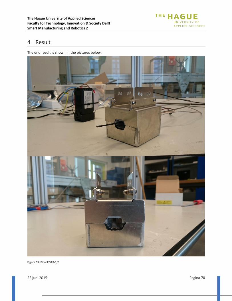
The Hague University of Applied Sciences Faculty for Technology, Innovation & Society Delft Smart Manufacturing and Robotics 2
25 juni 2015 Pagina 70
4 Result
The end result is shown in the pictures below.
Figure 55: Final EOAT-1,2
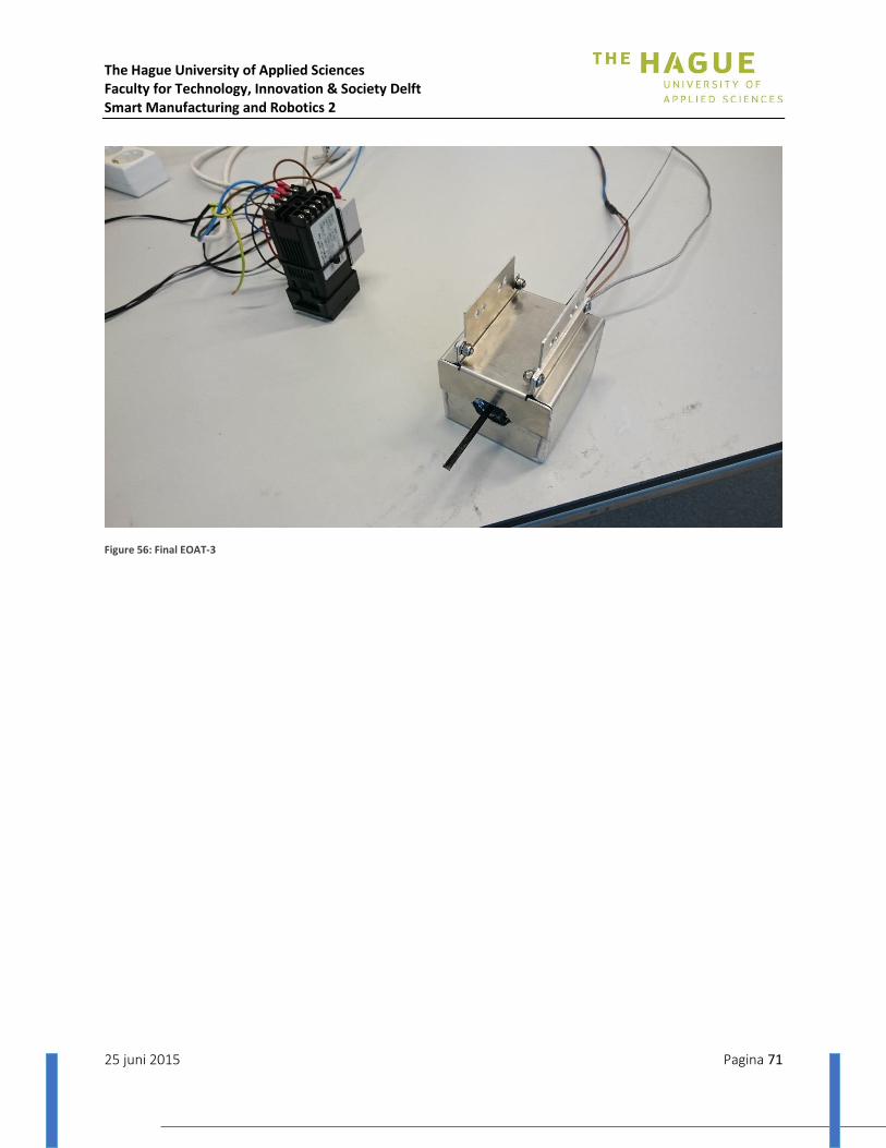
The Hague University of Applied Sciences Faculty for Technology, Innovation & Society Delft Smart Manufacturing and Robotics 2
25 juni 2015 Pagina 71
Figure 56: Final EOAT-3

The Hague University of Applied Sciences Faculty for Technology, Innovation & Society Delft Smart Manufacturing and Robotics 2
25 juni 2015 Pagina 72
Appendix VI: Test report End of Arm Tool and Filament
FACULTY FOR TECHNOLO GY, INNOVATION & SOC IETY
TEST REPORT END OF ARM TOOL AND FILAMENT
Name: Dirk van Trigt
Rick den Ouden
Course: SMR2 - Project
Period: April 2015 – July 2015
Tutor: Ir. T. Brilleman

The Hague University of Applied Sciences Faculty for Technology, Innovation & Society Delft Smart Manufacturing and Robotics 2
25 juni 2015 Pagina 73
Content 1 Introduction ............................................................................................................................................... 74
2 Theory ............................................................................................................................................................. 74
2 Test ............................................................................................................................................................. 75
2.1 Test goals ........................................................................................................................................... 75
2.2 Test setup .......................................................................................................................................... 75
3 Results ........................................................................................................................................................ 77
4 Conclusion ...................................................................................................... Error! Bookmark not defined.
The Hague University of Applied Sciences Faculty for Technology, Innovation & Society Delft Smart Manufacturing and Robotics 2
25 juni 2015 Pagina 74
1. Introduction The main goal of this project is to wrap polypropylene glass fiber reinforced filament around a pressure
vessel. The End Of Arm Tool (EOAT), the tool at the end of the robot that is used to perform tasks, is an
important part in the system and therefor will be developed and tested thoroughly.
2. Theory The End Of Arm Tool consists of a milled block of aluminum that encloses a heating element. This heating
element generates heat and conducts this heat through the aluminum block to the tape that is pulled
through a narrow opening in the aluminum block. While the tape is pulled through, the polypropylene
reaches a viscose state which is necessary to make the filament stick to the pressure vessel or the
previous layer of filament. This complicated process is yet unknown and research is therefore needed.

The Hague University of Applied Sciences Faculty for Technology, Innovation & Society Delft Smart Manufacturing and Robotics 2
25 juni 2015 Pagina 75
3. Test
3.1 Test goals
First the end of arm tool needs to be tested to get the following information:
1. Heating capacity of the heating element;
2. Isolation of the heating element to ensure that not too much heat is lost;
Second the filament has to be tested for:
3. Verification of specifications, predominately:
a. The maximum heating temperature before degrading;
b. The temperature range of viscose state;
c. the self-lubricating temperature;
4. Determine the right temperature of the filament so it:
a. Sticks to the plastic pressure vessel
b. Sticks to the previous layer of filament
Third the filament in combination with the end of arm tool:
5. Determine the right throughput speed of the filament through the end of arm tool;
6. Determine the necessary force to pull the filament through the end of arm tool;
3.2 Test setup
The end of arm tool will be connected to a thermistor and an Arduino, as shown in Figure 57, which is able
to give feedback about the temperature which the heating element has reached. With a thermal camera,
the heat loss at of the EOAT will be registered and compared to determine if there is not too much heat
loss in the process.
Figure 57: Test setup
The maximum heating temperature of the filament will be verified by heating the filament until the
temperature (given in the material datasheet) is reached and measured with a thermal camera or infra-red
heat sensor.
The temperature range of viscose state will be verified by heating the filament till the temperature (given in
the material datasheet) is reached and measured with a thermal camera or infra-red heat sensor. After
comparing the maximum heating temperature and the temperature which is needed for a viscose state, a
temperature range will be determined in which the filament needs to be when it’s being wrapped.

The Hague University of Applied Sciences Faculty for Technology, Innovation & Society Delft Smart Manufacturing and Robotics 2
25 juni 2015 Pagina 76
Somewhere in this viscose state temperature range the filament becomes self-lubricating. The only way to
find out this temperature is to feed multiple strings of filament through the end of arm tool at different
temperatures and checking the residue left in the end of arm tool.
The determination of the right temperature at which the filament will stick the PP-pressure vessel or
another piece of tape can be achieved by heating the filament somewhere in the viscose state temperature
range, measure this temperature and apply it to one of these conducts.
When the right temperature is measured to let the filament stick to the plastic pressure vessel or the
previous layer of filament we can determine how long the filament needs to be heated before it reaches
this temperature. According to this time a throughput speed can be determined.
The necessary torque to pull the tape through the heating element at determined speed can be measured
with a spring scale or hanging a weight onto the filament.

The Hague University of Applied Sciences Faculty for Technology, Innovation & Society Delft Smart Manufacturing and Robotics 2
25 juni 2015 Pagina 77
4. Results
First test:
During the first test the insulation of the casing couldn’t withstand the heat. Therefor the glass wool
touching the aluminum block was switched with plaster board, see Figure 58.
Figure 58: Scorched glass wool
With the insulation the test could be continued. Using a thermal camera, we concluded that the
thermocouple wasn’t accurate. Although the thermocouple wasn’t accurate we could determine that the
estimated temperature before degradation is 250 °C. This result was measured with a contact free
thermometer. By using this tool we gained different measurement results when measuring in different
spots on the aluminum casing. Most constant results were gained measuring in the opening of the
aluminum casing where the heating slides in.
Second test
The thermocouple has been replaced with a thermistor normally used in a 3D printer. With the thermistor
wired through Arduino it works and can measure the high temperatures more accurate and keep the
heating element at a more constant temperature.

The Hague University of Applied Sciences Faculty for Technology, Innovation & Society Delft Smart Manufacturing and Robotics 2
25 juni 2015 Pagina 78
Third test:
Setting the temperature in the Arduino to 200 °C, 250 °C and 300 °C and pulling the tape through the
EOAT with a rate of 1 pressure vessel revolution per minute the results deviated greatly.
At 200 °C the tape doesn’t reach its self-lubricating temperature and leaves glass fiber behind in the
EOAT, see Figure 59.
Figure 59: Glass fibre sticking to the EOAT
With the Arduino set to 300 °C the tape reaches its self-lubricating temperature (250°C) and melts the
outer layer of the pressure vessel and stick to it.

The Hague University of Applied Sciences Faculty for Technology, Innovation & Society Delft Smart Manufacturing and Robotics 2
25 juni 2015 Pagina 79
5. Conclusion 1. Heating capacity of the heating element;
The heating capacity of the heating element is good. Conclusion is the set temperature of 250 degrees on the thermocouple which caused degrading. The thermocouple was not accurate. Reason for this was probably that the thermocouple was not calibrated right. 250 degrees Celsius was not the maximum heating capacity of the element so we can conclude that it is enough for this application.
2. Isolation of the heating element to ensure that not too much heat is lost;
We measured on different occasions around 300 degrees Celsius on the opening of the aluminum casing. After an hour of testing the materials we used to isolate the heat in de EOAT started to smoulder, dry out and losing their capacity to isolate the heat. After 60 minutes of testing the steel casing that surrounds the isolation material and the aluminum block became too hot to touch, which wasn’t the case at the start of the test.
3. Verification of specifications, predominately:
a. The maximum heating temperature before degrading;
The given temperature from the thermocouple was 250 degrees Celsius.
b. The temperature range of viscose state;
The given temperature from the thermocouple ranges between 200 and 249 degrees Celsius.
c. the self-lubricating temperature;
The given temperature by the Arduino through the thermistor was 300 degrees Celsius.
4. Determine the right temperature of the filament so it:
a. Sticks to the plastic pressure vessel
The given temperature by the Arduino through the thermistor was 300 degrees Celsius.
b. Sticks to the previous layer of filament
The given temperature by the Arduino through the thermistor was 300 degrees Celsius.
5. Determine the right throughput speed of the filament through the end of arm tool;
1 meter per minute.
6. Determine the necessary force to pull the filament through the end of arm tool;
About 10 Newton.

The Hague University of Applied Sciences Faculty for Technology, Innovation & Society Delft Smart Manufacturing and Robotics 2
25 juni 2015 Pagina 80
Appendix VII: Sensor research
FACULTY FOR TECHNOLO GY, INNOVATION & SOC IETY
TEMPERATURE SENSOR REPORT
Name: Marc Cornet
Course: SMR2 - Project
Period: April 2015 – July 2015
Tutor: Ir. T. Brilleman
The Hague University of Applied Sciences Faculty for Technology, Innovation & Society Delft Smart Manufacturing and Robotics 2
25 juni 2015 Pagina 81
Content 1 Abstract .......................................................................................................... Error! Bookmark not defined.
2 Introduction ............................................................................................................................................... 82
3 Temperature sensors ................................................................................................................................. 83
3.1 Contact temperature sensors ............................................................................................................ 83
3.1.1 Thermistors ............................................................................................................................... 83
3.1.2 Resistence thermometer ........................................................................................................... 83
3.1.3 Thermocouple ........................................................................................................................... 83
3.2 Non-contact temperature sensor ...................................................................................................... 84
3.3 Choosing a sensor .............................................................................................................................. 84
4 Choosing the IR-sensor .............................................................................................................................. 85
4.1 Melexis sensor ................................................................................................................................... 86
5 Initial Tests ................................................................................................................................................. 86
5.1 Experiment 1 ..................................................................................................................................... 86
5.2 Experiment 2 ..................................................................................................................................... 89
5.3 Conclusion ......................................................................................................................................... 90
6 Using the sensor......................................................................................................................................... 90
6.1 Testing under expected working conditions ..................................................................................... 90
6.2 Increasing the distance ...................................................................................................................... 92
6.3 Decreasing the distance. ................................................................................................................... 93
6.4 Conclusion ......................................................................................................................................... 94
7 Conclusion .................................................................................................................................................. 95
The Hague University of Applied Sciences Faculty for Technology, Innovation & Society Delft Smart Manufacturing and Robotics 2
25 juni 2015 Pagina 82
2 Introduction
In this project polypropylene glass fibre enforced tape is fed through a heating element. After heating it needs to be applied and wrapped around a plastic pressure vessel. If this process is completed with the correct temperature the wrap of polypropylene glass fibre enforced tape around the pressure vessel will make the plastic pressure vessel as strong as a steel one. To know if the tape is heated to the right temperature and applied with the right temperature to the pressure vessel there is need for a temperature sensor. Measuring if the tape leaves the heating element at the correct temperature is also invaluable for automatic temperature correction. This correction can be achieved for example by adjusting the power input of the heating element or the speed of the tape through the heating element. In order to measure the temperature of the tape after it leaves the heating element a sensor needs to be chosen. In the following chapter a brief rundown of the available temperature sensors is given. It is decided that for our needs an IR-sensor will be a good choice. The details about this choice can be found in chapter 4. After the initial choice was made the sensor however took more time to arrive than hoped and turned out to be quite dead on arrival. This resulted in using an IR-sensor from Melexis. A few initial tests, detailed in chapter 5, gave a good idea about how the sensor worked with the default settings and software. The performance of the sensor was also compared to our reference sensor, the Testo 835-T2. The results of these tests are written in chapter 6. The conclusion of this report is the last chapter.

The Hague University of Applied Sciences Faculty for Technology, Innovation & Society Delft Smart Manufacturing and Robotics 2
25 juni 2015 Pagina 83
3 Temperature sensors
A temperature sensor is a part that converts temperature to a procesable electrical output. These sensors
can be divided in two separate groups: Contact and Non-contact.
3.1 Contact temperature sensors
Contact temperature sensors are using physical contact to determine temperature by conduction. These
kinds of sensors are able to measure temperature from solids, liquids or gases in a wide range of
temperature depending on the selected sensor. Example of a contact temperature sensor is a lollipop
thermometer.
3.1.1 Thermistors
Thermistors are thermally sensitive resistors whose prime function is to exhibit a large, predictable and
precise change in electrical resistance when subjected to a corresponding change in body temperature.
Negative Temperature Coefficient (NTC) thermistors exhibit a decrease in electrical resistance when
subjected to an increase in body temperature and positive Temperature Coefficient (PTC) thermistors
exhibit an increase in electrical resistance when subjected to an increase in body temperature.
3.1.2 Resistence thermometer
Resistance thermometers, also called resistance temperature detectors (RTDs), are sensors used to
measure temperature by correlating the resistance of the RTD element with temperature. Most RTD
elements consist of a length of fine coiled wire wrapped around a ceramic or glass core. The element is
usually quite fragile, so it is often placed inside a sheathed probe to protect it. The RTD element is made
from a pure material, typically platinum, nickel or copper. The material has a predictable change in
resistance as the temperature changes and it is this predictable change that is used to determine
temperature. They are slowly replacing the use of thermocouples in many industrial applications below
600 °C, due to higher accuracy and repeatability.
3.1.3 Thermocouple
A Thermocouple is a temperature-measuring device consisting of two dissimilar conductors that contact
each other at one or more spots. Here a temperature difference is experienced by the different
conductors (or semiconductors). It produces a voltage when the temperature of one of the spots differs
from the reference temperature at other parts of the circuit. Thermocouples are a widely used type of
temperature sensor for measurement and control, and can also convert a temperature gradient into
electricity. Commercial thermocouples are inexpensive, interchangeable, are supplied with standard
connectors, and can measure a wide range of temperatures. In contrast to most other methods of
temperature measurement, thermocouples are self-powered and require no external form of excitation.
The main limitation of thermocouples is accuracy; system errors of less than one degree Celsius (°C) can
be difficult to achieve.
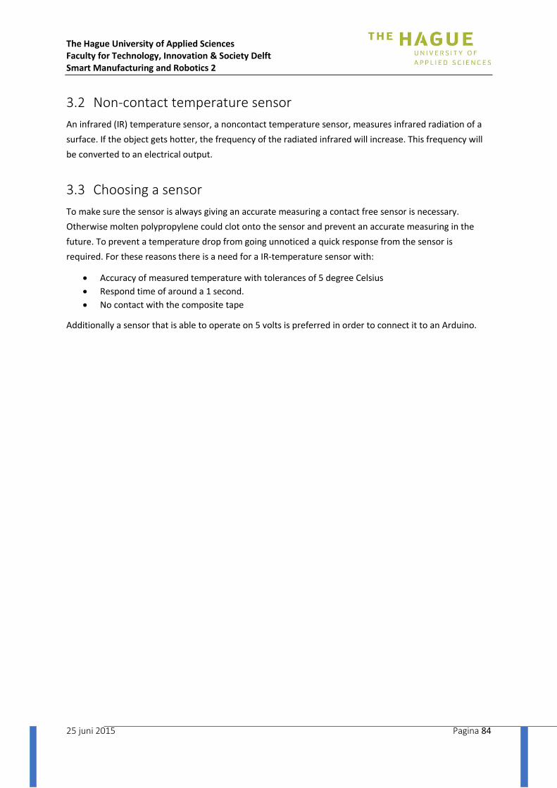
The Hague University of Applied Sciences Faculty for Technology, Innovation & Society Delft Smart Manufacturing and Robotics 2
25 juni 2015 Pagina 84
3.2 Non-contact temperature sensor
An infrared (IR) temperature sensor, a noncontact temperature sensor, measures infrared radiation of a
surface. If the object gets hotter, the frequency of the radiated infrared will increase. This frequency will
be converted to an electrical output.
3.3 Choosing a sensor
To make sure the sensor is always giving an accurate measuring a contact free sensor is necessary.
Otherwise molten polypropylene could clot onto the sensor and prevent an accurate measuring in the
future. To prevent a temperature drop from going unnoticed a quick response from the sensor is
required. For these reasons there is a need for a IR-temperature sensor with:
Accuracy of measured temperature with tolerances of 5 degree Celsius
Respond time of around a 1 second.
No contact with the composite tape
Additionally a sensor that is able to operate on 5 volts is preferred in order to connect it to an Arduino.

The Hague University of Applied Sciences Faculty for Technology, Innovation & Society Delft Smart Manufacturing and Robotics 2
25 juni 2015 Pagina 85
4 IR-sensor choice
To measure the temperature a contact-less sensor would be needed. There are two options that were considered. One option would be to buy an industrial IR sensor, but a quick look at the Farnell website showed that these would cost several hundreds of euros.
So given the support school gives for using the Arduino it seems reasonable to explore those options. The first option considered was a sensor from Texas Instruments. Texas Instruments is known to provide their IC’s for free in the form of samples. However the sensor was not usable in sample form due to the package it comes in: a ball grid package which would offer some hurdles to successfully use this sensor as soldering this would be a real challenge.
Another mentioned sensor on several Arduino sites was from Melexis, the MLX90614. When trying to find a vendor for this sensor it turned out that Adafruit (a popular American supplier of Arduino accessories, complete with software libraries to use it, with European shops carrying some of their catalog in their online shops) offered both these two sensors, so the search stopped here. The TMP007 would even come with an easy to use breakout board with all the supporting electronics, a few resistors and capacitors, already soldered on it as well.
Table 12: IR-sensor choices
Melexis MLX90614 TI TMP007
Package: Tin can with radial leads Ball grid, but Adafruit offers breakout board with male headers
Sampling / averaging Number of samples per reading; % rise / drop between samples adjustable, single sample quicker than TMP007
Sample speed of 4 per second.
1/2/4/8/16 samples per reading with arduino
Connectivity I2C; But not compatible with arduino’s wire.h library, but adafruit support
I2C
Accuracy ±1°C from -40 °C to 120 °C ±2°C typ, from -15°C to 80°C
Voltage 3Ven5V 5V
Outside temperature influence on sensor stability
Severity unknown; More expensive
versions with compensation
techniques
Severity unknown
Price Adafruit: $15.95, but with more
expensive versions available via
other vendors
Adafruit: $12.50
Because the extra functionality of the Melexis sensor was hard to value just from reading about it in the datasheet the easier I2C communication with the TMP007 seemed a very big plus, this is why the TMP007 was ordered.

The Hague University of Applied Sciences Faculty for Technology, Innovation & Society Delft Smart Manufacturing and Robotics 2
25 juni 2015 Pagina 86
4.1 Melexis sensor
The sensor arrived but never worked. Because it took more time than expected for the sensor to arrive
another vendor was found. This vendor carried the Melexis sensor, but with a breakout board. In
hindsight this would have been the preferred choice since the shipping made up for the price difference
and the break-out board also made up the difference in easy connectivity.
5 Initial Tests
To get a rough idea of how well the sensor works two experiments are conducted. The first experiment
will try to give insight in the measured temperature when the object temperature is known with two
different distances. The second experiment will try to determine what the sensor will report when using a
realistic distance from the sensor with a smaller sized object that does not cover the whole viewing area
of the sensor. The sensor transmits both its own temperature and the temperature from the object it
measures over I2C. The default Adafruit program with 4 samples per reading, resulting in 1 measurement
each second, was used.
5.1 Experiment 1
To determine the difference between a known temperature and the measured temperature ice-water
and boiling water is used. Especially the ice water is great for its temperature stability over time. Using
two rings and a thin plastic container, the ice-water and the boiling water is placed on two different
distances from the sensor. This can be seen in the picture below. Ring 1 gives a distance of about 1.5 cm
to the sensor. Ring two adds another centimetre distance between the plastic container with the water.
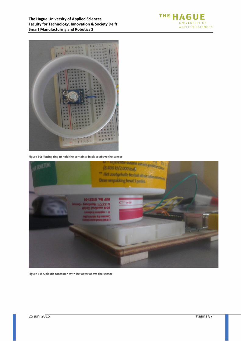
The Hague University of Applied Sciences Faculty for Technology, Innovation & Society Delft Smart Manufacturing and Robotics 2
25 juni 2015 Pagina 87
Figure 60: Placing ring to hold the container in place above the sensor
Figure 61: A plastic container with ice water above the sensor
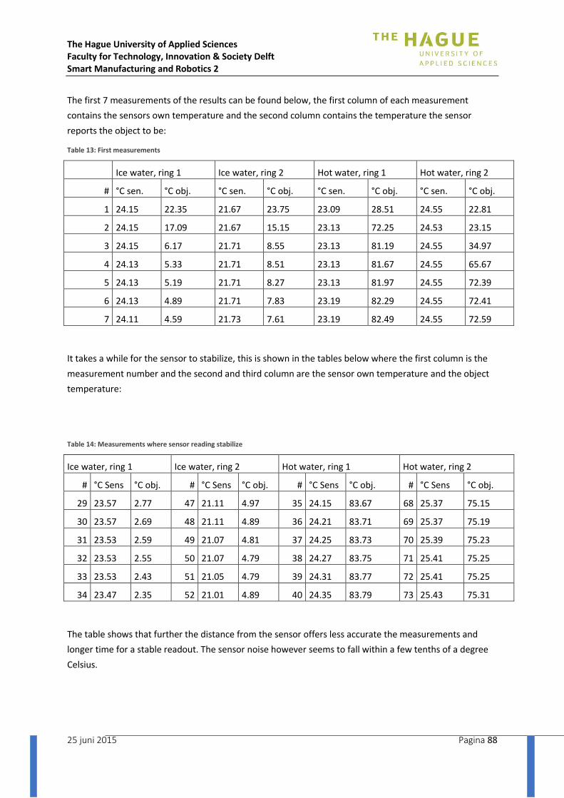
The Hague University of Applied Sciences Faculty for Technology, Innovation & Society Delft Smart Manufacturing and Robotics 2
25 juni 2015 Pagina 88
The first 7 measurements of the results can be found below, the first column of each measurement
contains the sensors own temperature and the second column contains the temperature the sensor
reports the object to be:
Table 13: First measurements
Ice water, ring 1 Ice water, ring 2 Hot water, ring 1 Hot water, ring 2
# °C sen. °C obj. °C sen. °C obj. °C sen. °C obj. °C sen. °C obj.
1 24.15 22.35 21.67 23.75 23.09 28.51 24.55 22.81
2 24.15 17.09 21.67 15.15 23.13 72.25 24.53 23.15
3 24.15 6.17 21.71 8.55 23.13 81.19 24.55 34.97
4 24.13 5.33 21.71 8.51 23.13 81.67 24.55 65.67
5 24.13 5.19 21.71 8.27 23.13 81.97 24.55 72.39
6 24.13 4.89 21.71 7.83 23.19 82.29 24.55 72.41
7 24.11 4.59 21.73 7.61 23.19 82.49 24.55 72.59
It takes a while for the sensor to stabilize, this is shown in the tables below where the first column is the
measurement number and the second and third column are the sensor own temperature and the object
temperature:
Table 14: Measurements where sensor reading stabilize
Ice water, ring 1 Ice water, ring 2 Hot water, ring 1 Hot water, ring 2
# °C Sens °C obj. # °C Sens °C obj. # °C Sens °C obj. # °C Sens °C obj.
29 23.57 2.77 47 21.11 4.97 35 24.15 83.67 68 25.37 75.15
30 23.57 2.69 48 21.11 4.89 36 24.21 83.71 69 25.37 75.19
31 23.53 2.59 49 21.07 4.81 37 24.25 83.73 70 25.39 75.23
32 23.53 2.55 50 21.07 4.79 38 24.27 83.75 71 25.41 75.25
33 23.53 2.43 51 21.05 4.79 39 24.31 83.77 72 25.41 75.25
34 23.47 2.35 52 21.01 4.89 40 24.35 83.79 73 25.43 75.31
The table shows that further the distance from the sensor offers less accurate the measurements and
longer time for a stable readout. The sensor noise however seems to fall within a few tenths of a degree
Celsius.
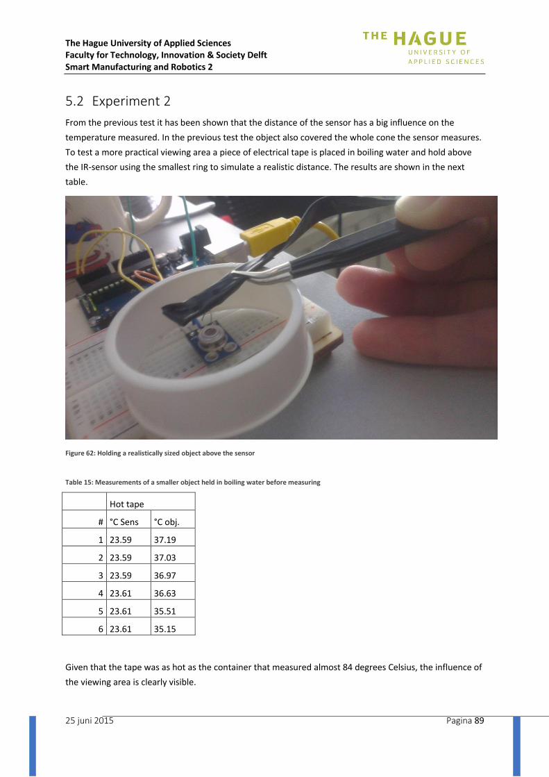
The Hague University of Applied Sciences Faculty for Technology, Innovation & Society Delft Smart Manufacturing and Robotics 2
25 juni 2015 Pagina 89
5.2 Experiment 2
From the previous test it has been shown that the distance of the sensor has a big influence on the
temperature measured. In the previous test the object also covered the whole cone the sensor measures.
To test a more practical viewing area a piece of electrical tape is placed in boiling water and hold above
the IR-sensor using the smallest ring to simulate a realistic distance. The results are shown in the next
table.
Figure 62: Holding a realistically sized object above the sensor
Table 15: Measurements of a smaller object held in boiling water before measuring
Hot tape
# °C Sens °C obj.
1 23.59 37.19
2 23.59 37.03
3 23.59 36.97
4 23.61 36.63
5 23.61 35.51
6 23.61 35.15
Given that the tape was as hot as the container that measured almost 84 degrees Celsius, the influence of
the viewing area is clearly visible.

The Hague University of Applied Sciences Faculty for Technology, Innovation & Society Delft Smart Manufacturing and Robotics 2
25 juni 2015 Pagina 90
5.3 Conclusion
Given the influence of the distance to the object measured it is advised to place the sensor closer to the
tape rather than further. From the second experiment the object size also showed to influence the
measured temperature due to the viewing angle of the sensor. In order to be able to still use the
measured data the background behind the tape may have to be kept at the same temperature. The best
solution is probably to place the sensor quite close to the heating tool, while blocking the view of the
sensor behind the tape. This closer placement should allow for this extra extruding material to block the
view of the sensor from the background without interfering with the winding process. While the sensor
readout might not be correct in an absolute sense, it is expected to be usable when the readouts are
calibrated with the real world results.
6. Using the sensor
From the initial experiments detailed in the previous chapter a basic idea about the sensor performance
was formed. It was suggested that the sensor needed a rather small distance to measure correctly. In this
chapter the sensor performance will be examined more closely. This will be done by comparing the
measurements of our Melexis MLX90614 IR-sensor with the Testo 835-T2.
6.1 Testing under expected working conditions
From the previous chapter we already knew that the sensor distance from the tape should be kept rather
small. In the lab we placed a piece of wood next to the sensor, when holding the tape at this distance
there would be 11 mm between tape and sensor.
The tape was heated using a soldering iron. Determining if the tape was hot enough was done by visual
inspection This is when the plastic begins to melt and the tape becomes slightly wider, but before the
plastic drips away from the glass fibre.
The hot tape was held in front of the Melexis sensor and in front of that setup the IR handgun was held.
With a mobile phone both the reference sensor and the Melexis sensor output were captured in a movie.
A picture of the test setup can be found below, and the results of the tests are found in the graphs below.
The time on the horizontal axis is the time taken from the video.
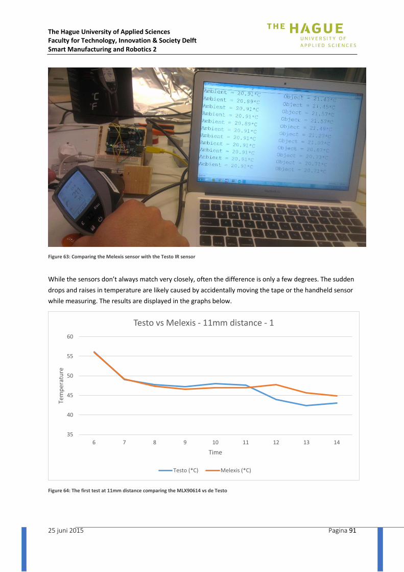
The Hague University of Applied Sciences Faculty for Technology, Innovation & Society Delft Smart Manufacturing and Robotics 2
25 juni 2015 Pagina 91
Figure 63: Comparing the Melexis sensor with the Testo IR sensor
While the sensors don’t always match very closely, often the difference is only a few degrees. The sudden
drops and raises in temperature are likely caused by accidentally moving the tape or the handheld sensor
while measuring. The results are displayed in the graphs below.
Figure 64: The first test at 11mm distance comparing the MLX90614 vs de Testo
35
40
45
50
55
60
6 7 8 9 10 11 12 13 14
Tem
per
atu
re
Time
Testo vs Melexis - 11mm distance - 1
Testo (*C) Melexis (*C)
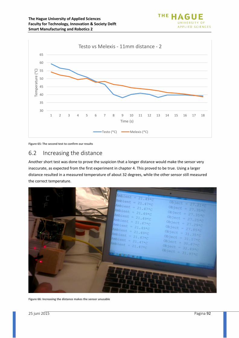
The Hague University of Applied Sciences Faculty for Technology, Innovation & Society Delft Smart Manufacturing and Robotics 2
25 juni 2015 Pagina 92
Figure 65: The second test to confirm our results
6.2 Increasing the distance
Another short test was done to prove the suspicion that a longer distance would make the sensor very
inaccurate, as expected from the first experiment in chapter 4. This proved to be true. Using a larger
distance resulted in a measured temperature of about 32 degrees, while the other sensor still measured
the correct temperature.
Figure 66: Increasing the distance makes the sensor unusable
30
35
40
45
50
55
60
65
1 2 3 4 5 6 7 8 9 10 11 12 13 14 15 16 17 18
Tem
per
atu
re (
°C)
Time (s)
Testo vs Melexis - 11mm distance - 2
Testo (*C) Melexis (*C)
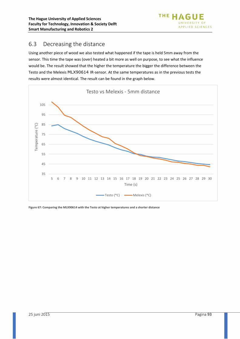
The Hague University of Applied Sciences Faculty for Technology, Innovation & Society Delft Smart Manufacturing and Robotics 2
25 juni 2015 Pagina 93
6.3 Decreasing the distance
Using another piece of wood we also tested what happened if the tape is held 5mm away from the
sensor. This time the tape was (over) heated a bit more as well on purpose, to see what the influence
would be. The result showed that the higher the temperature the bigger the difference between the
Testo and the Melexis MLX90614 IR-sensor. At the same temperatures as in the previous tests the
results were almost identical. The result can be found in the graph below.
Figure 67: Comparing the MLX90614 with the Testo at higher temperatures and a shorter distance
35
45
55
65
75
85
95
105
5 6 7 8 9 10 11 12 13 14 15 16 17 18 19 20 21 22 23 24 25 26 27 28 29 30
Tem
per
atu
re (
°C)
Time (s)
Testo vs Melexis - 5mm distance
Testo (*C) Melexis (*C)
The Hague University of Applied Sciences Faculty for Technology, Innovation & Society Delft Smart Manufacturing and Robotics 2
25 juni 2015 Pagina 94
6.4 Conclusion
The MLX90614 IR-sensor was tested under a variety of conditions with the tape that is to be used for
the winding process. The first test with a distance of about 11mm between the tape and the sensor
resulted in a very usable reading from the Melexis sensor. It showed only a few degrees difference
between the Melexis and Testo sensor that is used as a reference. When the distance was decreased the
difference was still only a few degrees at the lower temperatures as tested when the distance was 11mm.
However at higher temperatures (> 65 °C) the MLX90614 reported a much higher temperature than the
Testo. This difference however will not hinder the usability of the results.
When the distance is increased, the measurement become unusable, this was to be expected given the
earlier tests in chapter 4. In that chapter it is also briefly explained how the cone shaped viewing area of
the sensor will only see the hot tape as a part of the whole object.
Since both the tape and the Testo sensor where held in place manually during these tests, creating inaccuracies in the reported distance and the measured temperature, it was deemed unnecessary to explore the optimum distance any further at this point. However when placing this sensor in the final product this has to be taken into account.
The takeaway is that both the 5mm and 11mm distance gave usable results, any differences between the Testo and the Melexis can be compensated with calibration in the final product.

The Hague University of Applied Sciences Faculty for Technology, Innovation & Society Delft Smart Manufacturing and Robotics 2
25 juni 2015 Pagina 95
7. Conclusion
In order to determine the temperature of the tape leaving the heating element a list of sensor types was made. From all the different temperature sensors available an IR-sensor was chosen due to the Non-contact nature of this type of sensor. This will prevent the tape from influencing the sensor performance over time if tape residue will stick to the sensor.
Because industrial sensors were to expensive it was decided to try to use a cheaper sensor in combination with an Arduino. The choice was between the TI TMP007 and the Melexis MLX90614. Both very comparable for our needs, but the TI sensor from the initial vendor came in a easier to use form. This sensor however did not work properly and the other choice, the MLX90614, was ordered after another vendor was found that also sold this sensor on a so called break-out board.
This sensor was tested as written in chapter 5 and 6 and turned out to be usable in this project. When compared to our reference sensor, the Testo 835-T2, the differences at lower temperatures (< 60 °C) and smaller distances (5 mm, 11 mm) were only a few degrees celcius. At larger distances the sensor is unusable and at higher temperatures (> 65 °C) the MLX90614 will report a temperature that is too high.
With calibration the MLX90614 is a good sensor for this project, meeting the requirements and being much cheaper than the professional alternatives.
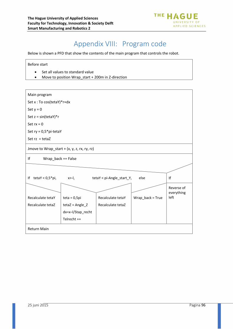
The Hague University of Applied Sciences Faculty for Technology, Innovation & Society Delft Smart Manufacturing and Robotics 2
25 juni 2015 Pagina 96
Appendix VIII: Program code Below is shown a PFD that show the contents of the main program that controls the robot.
Before start
Set all values to standard value
Move to position Wrap_start + 200m in Z-direction
Main program
Set x : To cos(tetaY)*r+dx
Set y = 0
Set z = sin(tetaY)*r
Set rx = 0
Set ry = 0,5*pi-tetaY
Set rz = tetaZ
Jmove to Wrap_start + (x, y, z, rx, ry, rz)
If Wrap_back == False
If tetaY < 0,5*pi, x>-l, tetaY < pi-Angle_start_Y, else If
Reverse of everything left Recalculate tetaY
Recalculate tetaZ
teta = 0,5pi
tetaZ = Angle_Z
dx=x–l/Stap_recht
Telrecht ++
Recalculate tetaY
Recalculate tetaZ
Wrap_back = True
Return Main

The Hague University of Applied Sciences Faculty for Technology, Innovation & Society Delft Smart Manufacturing and Robotics 2
25 juni 2015 Pagina 97
Appendix IX: Technical drawings

The Hague University of Applied Sciences Faculty for Technology, Innovation & Society Delft Smart Manufacturing and Robotics 2
25 juni 2015 Pagina 98

The Hague University of Applied Sciences Faculty for Technology, Innovation & Society Delft Smart Manufacturing and Robotics 2
25 juni 2015 Pagina 99

The Hague University of Applied Sciences Faculty for Technology, Innovation & Society Delft Smart Manufacturing and Robotics 2
25 juni 2015 Pagina 100
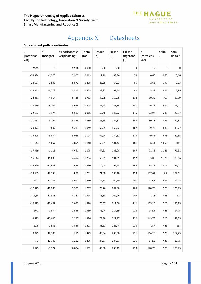
The Hague University of Applied Sciences Faculty for Technology, Innovation & Society Delft Smart Manufacturing and Robotics 2
25 juni 2015 Pagina 101
Appendix X: Datasheets Spreadsheet path coordinates
Z (rotatieas vat)
Y (hoogte)
X (horizontale verplaatsing)
Theta [rad]
Graden [o]
Pulsen [-]
Pulsen afgerond [-]
Z (rotatieas vat)
delta Z
som delta Z
-24,45 0 5,918 0,000 0,00 0,00 0 0 0 0
-24,384 -1,276 5,907 0,213 12,19 33,86 34 0,66 0,66 0,66
-24,187 -2,538 5,872 0,408 23,38 64,93 65 2,63 1,97 2,63
-23,861 -3,772 5,815 0,575 32,97 91,58 92 5,89 3,26 5,89
-23,411 -4,964 5,735 0,713 40,88 113,55 114 10,39 4,5 10,39
-22,839 -6,102 5,634 0,825 47,28 131,34 131 16,11 5,72 16,11
-22,153 -7,174 5,513 0,916 52,46 145,72 146 22,97 6,86 22,97
-21,362 -8,167 5,374 0,989 56,65 157,37 157 30,88 7,91 30,88
-20,473 -9,07 5,217 1,049 60,09 166,92 167 39,77 8,89 39,77
-19,495 -9,874 5,045 1,098 62,94 174,82 175 49,55 9,78 49,55
-18,44 -10,57 4,859 1,140 65,31 181,42 181 60,1 10,55 60,1
-17,319 -11,15 4,661 1,175 67,31 186,98 187 71,31 11,21 71,31
-16,144 -11,608 4,454 1,204 69,01 191,69 192 83,06 11,75 83,06
-14,929 -11,938 4,24 1,230 70,45 195,68 196 95,21 12,15 95,21
-13,689 -12,138 4,02 1,251 71,68 199,10 199 107,61 12,4 107,61
-13,1 -12,186 3,917 1,260 72,18 200,50 201 113,5 5,89 113,5
-12,375 -12,289 3,579 1,287 73,76 204,90 205 120,75 7,25 120,75
-11,65 -12,383 3,241 1,315 75,33 209,26 209 128 7,25 128
-10,925 -12,467 3,093 1,328 76,07 211,30 211 135,25 7,25 135,25
-10,2 -12,54 2,565 1,369 78,44 217,89 218 142,5 7,25 142,5
-9,475 -12,605 2,227 1,396 79,98 222,17 222 149,75 7,25 149,75
-8,75 -12,66 1,888 1,423 81,52 226,44 226 157 7,25 157
-8,025 -12,706 1,55 1,449 83,04 230,68 231 164,25 7,25 164,25
-7,3 -12,742 1,212 1,476 84,57 234,91 235 171,5 7,25 171,5
-6,575 -12,77 0,874 1,502 86,08 239,12 239 178,75 7,25 178,75
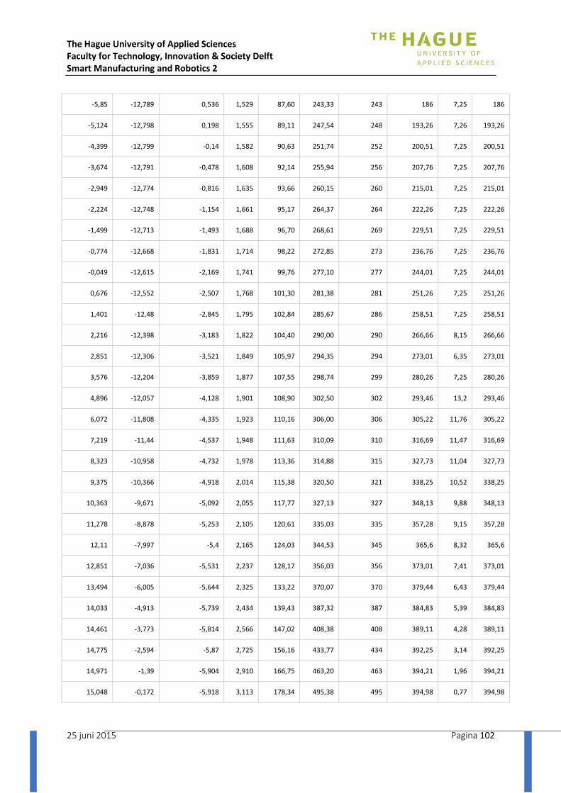
The Hague University of Applied Sciences Faculty for Technology, Innovation & Society Delft Smart Manufacturing and Robotics 2
25 juni 2015 Pagina 102
-5,85 -12,789 0,536 1,529 87,60 243,33 243 186 7,25 186
-5,124 -12,798 0,198 1,555 89,11 247,54 248 193,26 7,26 193,26
-4,399 -12,799 -0,14 1,582 90,63 251,74 252 200,51 7,25 200,51
-3,674 -12,791 -0,478 1,608 92,14 255,94 256 207,76 7,25 207,76
-2,949 -12,774 -0,816 1,635 93,66 260,15 260 215,01 7,25 215,01
-2,224 -12,748 -1,154 1,661 95,17 264,37 264 222,26 7,25 222,26
-1,499 -12,713 -1,493 1,688 96,70 268,61 269 229,51 7,25 229,51
-0,774 -12,668 -1,831 1,714 98,22 272,85 273 236,76 7,25 236,76
-0,049 -12,615 -2,169 1,741 99,76 277,10 277 244,01 7,25 244,01
0,676 -12,552 -2,507 1,768 101,30 281,38 281 251,26 7,25 251,26
1,401 -12,48 -2,845 1,795 102,84 285,67 286 258,51 7,25 258,51
2,216 -12,398 -3,183 1,822 104,40 290,00 290 266,66 8,15 266,66
2,851 -12,306 -3,521 1,849 105,97 294,35 294 273,01 6,35 273,01
3,576 -12,204 -3,859 1,877 107,55 298,74 299 280,26 7,25 280,26
4,896 -12,057 -4,128 1,901 108,90 302,50 302 293,46 13,2 293,46
6,072 -11,808 -4,335 1,923 110,16 306,00 306 305,22 11,76 305,22
7,219 -11,44 -4,537 1,948 111,63 310,09 310 316,69 11,47 316,69
8,323 -10,958 -4,732 1,978 113,36 314,88 315 327,73 11,04 327,73
9,375 -10,366 -4,918 2,014 115,38 320,50 321 338,25 10,52 338,25
10,363 -9,671 -5,092 2,055 117,77 327,13 327 348,13 9,88 348,13
11,278 -8,878 -5,253 2,105 120,61 335,03 335 357,28 9,15 357,28
12,11 -7,997 -5,4 2,165 124,03 344,53 345 365,6 8,32 365,6
12,851 -7,036 -5,531 2,237 128,17 356,03 356 373,01 7,41 373,01
13,494 -6,005 -5,644 2,325 133,22 370,07 370 379,44 6,43 379,44
14,033 -4,913 -5,739 2,434 139,43 387,32 387 384,83 5,39 384,83
14,461 -3,773 -5,814 2,566 147,02 408,38 408 389,11 4,28 389,11
14,775 -2,594 -5,87 2,725 156,16 433,77 434 392,25 3,14 392,25
14,971 -1,39 -5,904 2,910 166,75 463,20 463 394,21 1,96 394,21
15,048 -0,172 -5,918 3,113 178,34 495,38 495 394,98 0,77 394,98

The Hague University of Applied Sciences Faculty for Technology, Innovation & Society Delft Smart Manufacturing and Robotics 2
25 juni 2015 Pagina 103
14,971 3,354 192,19 533,86 534 394,21 0,77 395,75
14,775 3,550 203,38 564,93 565 392,25 1,96 397,71
14,461 3,717 212,97 591,58 592 389,11 3,14 400,85
14,033 3,855 220,88 613,55 614 384,83 4,28 405,13
13,494 3,967 227,28 631,34 631 379,44 5,39 410,52
12,851 4,057 232,46 645,72 646 373,01 6,43 416,95
12,11 4,130 236,65 657,37 657 365,6 7,41 424,36
11,278 4,190 240,09 666,92 667 357,28 8,32 432,68
10,363 4,240 242,94 674,82 675 348,13 9,15 441,83
9,375 4,282 245,31 681,42 681 338,25 9,88 451,71
8,323 4,316 247,31 686,98 687 327,73 10,52 462,23
7,219 4,346 249,01 691,69 692 316,69 11,04 473,27
6,072 4,371 250,45 695,68 696 305,22 11,47 484,74
4,896 4,393 251,68 699,10 699 293,46 11,76 496,5
3,576 4,429 253,76 704,90 705 280,26 13,2 509,7
2,851 4,456 255,33 709,26 709 273,01 7,25 516,95
2,216 4,469 256,07 711,30 711 266,66 6,35 523,3
1,401 4,511 258,44 717,89 718 258,51 8,15 531,45
0,676 4,538 259,98 722,17 722 251,26 7,25 538,7
-0,049 4,564 261,52 726,44 726 244,01 7,25 545,95
-0,774 4,591 263,04 730,68 731 236,76 7,25 553,2
-1,499 4,618 264,57 734,91 735 229,51 7,25 560,45
-2,224 4,644 266,08 739,12 739 222,26 7,25 567,7
-2,949 4,671 267,60 743,33 743 215,01 7,25 574,95
-3,674 4,697 269,11 747,54 748 207,76 7,25 582,2
-4,399 4,723 270,63 751,74 752 200,51 7,25 589,45
-5,124 4,750 272,14 755,94 756 193,26 7,25 596,7
-5,85 4,776 273,66 760,15 760 186 7,26 603,96
-6,575 4,803 275,17 764,37 764 178,75 7,25 611,21

The Hague University of Applied Sciences Faculty for Technology, Innovation & Society Delft Smart Manufacturing and Robotics 2
25 juni 2015 Pagina 104
-7,3 4,829 276,70 768,61 769 171,5 7,25 618,46
-8,025 4,856 278,22 772,85 773 164,25 7,25 625,71
-8,75 4,883 279,76 777,10 777 157 7,25 632,96
-9,475 4,910 281,30 781,38 781 149,75 7,25 640,21
-10,2 4,937 282,84 785,67 786 142,5 7,25 647,46
-10,925 4,964 284,40 790,00 790 135,25 7,25 654,71
-11,65 4,991 285,97 794,35 794 128 7,25 661,96
-12,375 5,019 287,55 798,74 799 120,75 7,25 669,21
-13,689 5,042 288,90 802,50 802 107,61 13,14 682,35
-14,929 5,064 290,16 806,00 806 95,21 12,4 694,75
-16,144 5,090 291,63 810,09 810 83,06 12,15 706,9
-17,319 5,120 293,36 814,88 815 71,31 11,75 718,65
-18,44 5,155 295,38 820,50 821 60,1 11,21 729,86
-19,495 5,197 297,77 827,13 827 49,55 10,55 740,41
-20,473 5,247 300,61 835,03 835 39,77 9,78 750,19
-21,362 5,306 304,03 844,53 845 30,88 8,89 759,08
-22,153 5,379 308,17 856,03 856 22,97 7,91 766,99
-22,839 5,467 313,22 870,07 870 16,11 6,86 773,85
-23,411 5,575 319,43 887,32 887 10,39 5,72 779,57
-23,861 5,708 327,02 908,38 908 5,89 4,5 784,07
-24,187 5,867 336,16 933,77 934 2,63 3,26 787,33
-24,384 6,052 346,75 963,20 963 0,66 1,97 789,3
-24,45 6,254 358,34 995,38 995 0 0,66 789,96

The Hague University of Applied Sciences Faculty for Technology, Innovation & Society Delft Smart Manufacturing and Robotics 2
25 juni 2015 Pagina 105

The Hague University of Applied Sciences Faculty for Technology, Innovation & Society Delft Smart Manufacturing and Robotics 2
25 juni 2015 Pagina 106

The Hague University of Applied Sciences Faculty for Technology, Innovation & Society Delft Smart Manufacturing and Robotics 2
25 juni 2015 Pagina 107

The Hague University of Applied Sciences Faculty for Technology, Innovation & Society Delft Smart Manufacturing and Robotics 2
25 juni 2015 Pagina 108
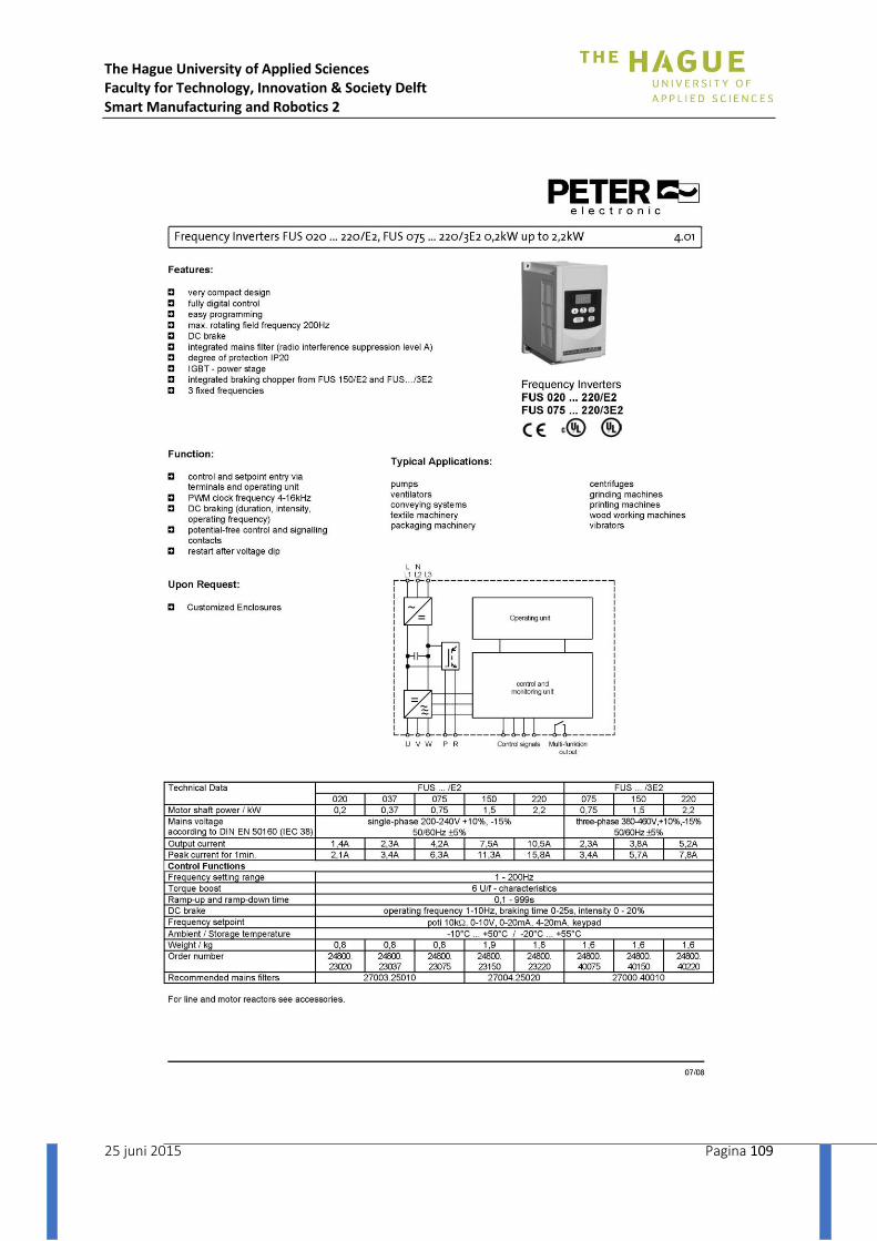
The Hague University of Applied Sciences Faculty for Technology, Innovation & Society Delft Smart Manufacturing and Robotics 2
25 juni 2015 Pagina 109

The Hague University of Applied Sciences Faculty for Technology, Innovation & Society Delft Smart Manufacturing and Robotics 2
25 juni 2015 Pagina 110
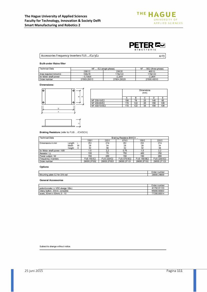
The Hague University of Applied Sciences Faculty for Technology, Innovation & Society Delft Smart Manufacturing and Robotics 2
25 juni 2015 Pagina 111
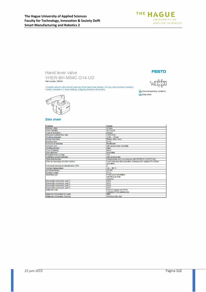
The Hague University of Applied Sciences Faculty for Technology, Innovation & Society Delft Smart Manufacturing and Robotics 2
25 juni 2015 Pagina 112

The Hague University of Applied Sciences Faculty for Technology, Innovation & Society Delft Smart Manufacturing and Robotics 2
25 juni 2015 Pagina 113
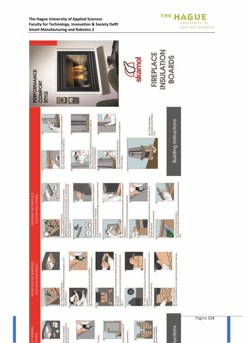
The Hague University of Applied Sciences Faculty for Technology, Innovation & Society Delft Smart Manufacturing and Robotics 2
25 juni 2015 Pagina 114

The Hague University of Applied Sciences Faculty for Technology, Innovation & Society Delft Smart Manufacturing and Robotics 2
25 juni 2015 Pagina 115

The Hague University of Applied Sciences Faculty for Technology, Innovation & Society Delft Smart Manufacturing and Robotics 2
25 juni 2015 Pagina 116
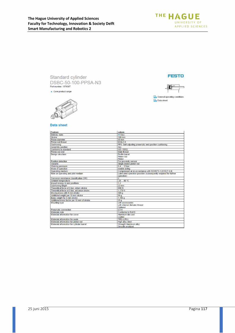
The Hague University of Applied Sciences Faculty for Technology, Innovation & Society Delft Smart Manufacturing and Robotics 2
25 juni 2015 Pagina 117

The Hague University of Applied Sciences Faculty for Technology, Innovation & Society Delft Smart Manufacturing and Robotics 2
25 juni 2015 Pagina 118

The Hague University of Applied Sciences Faculty for Technology, Innovation & Society Delft Smart Manufacturing and Robotics 2
25 juni 2015 Pagina 119

The Hague University of Applied Sciences Faculty for Technology, Innovation & Society Delft Smart Manufacturing and Robotics 2
25 juni 2015 Pagina 120
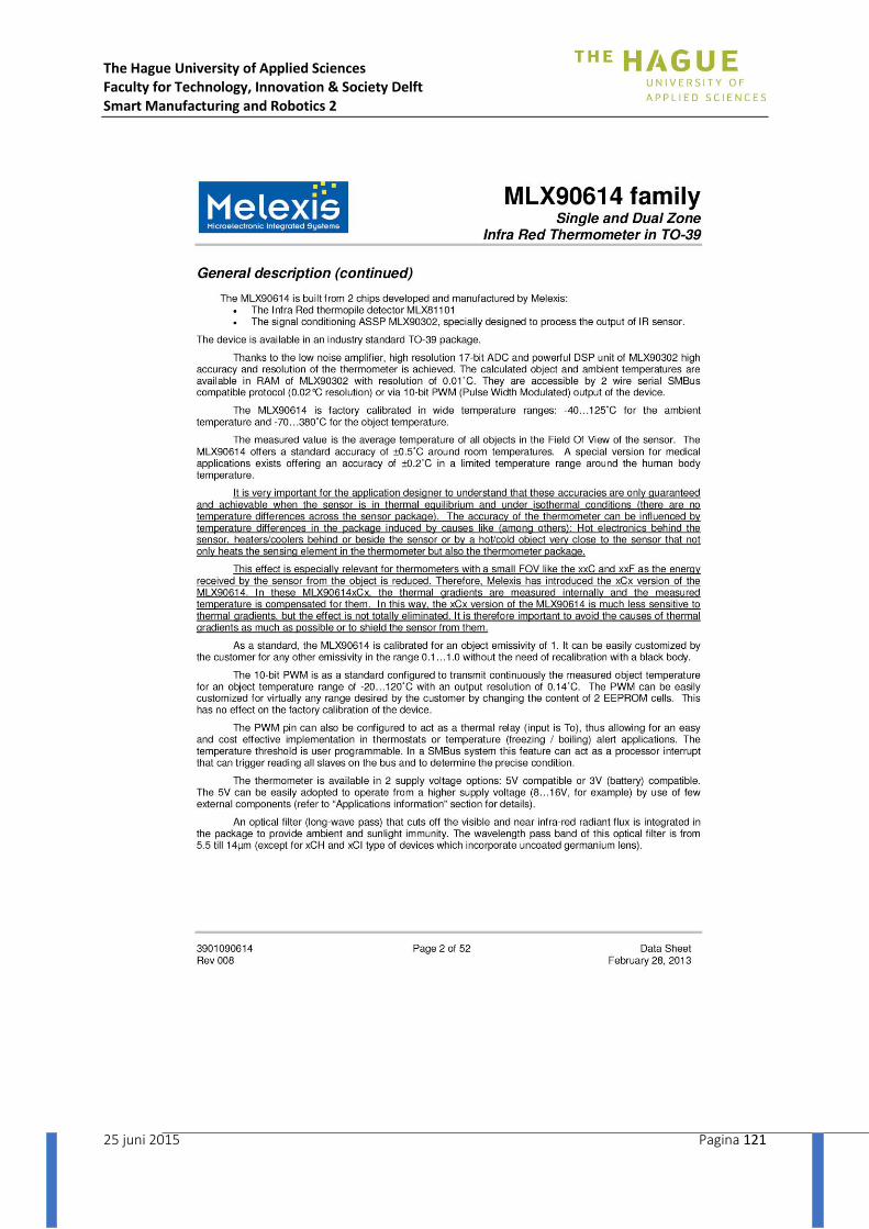
The Hague University of Applied Sciences Faculty for Technology, Innovation & Society Delft Smart Manufacturing and Robotics 2
25 juni 2015 Pagina 121

The Hague University of Applied Sciences Faculty for Technology, Innovation & Society Delft Smart Manufacturing and Robotics 2
25 juni 2015 Pagina 122
Appendix XI: Gantt Chart planning