Embed Size (px)
Citation preview
Final Report
GreenPilot – Pilot Boat with Minimal Environmental
Impact
Project Deliverable D8.3 Final Report
Authors: B. Ramne, J. Bomanson, P. Molander, J. Ellis, E. Errestad, H. Klintenberg
Document Status: Draft Version 20181128
Co-financed by:
Swedish Maritime Technology Forum
"GreenPilot is an exciting hands-on technical development
project with high set up goals to advance the environmental
profile of workboats and smaller ships.
SMTF is proud to be Project Lead of GreenPilot and
excited to contribute to the development of a methanol fuel
engine system for this segment.”
ScandiNAOS
”Making use of the possibilities of domestic production of
fossil free methanol and using this fuel for the transport
industry is a prerequisite to reach the target goal of
lowering greenhouse gases.
In this regard shipping has an important role as a platform
for development and applied demonstrations - applications
highly relevant for land transport as well.”
SSPA
"SSPA is committed to developing sustainable solutions for
shipping. The GreenPilot project objective of
demonstrating bio-methanol as a low emissions, low
environmental impact fuel is a great initiative for
developing solutions for smaller ships and SSPA is excited
to be part of the project team."
Swedish Transport Administration
"Through our participation in the GreenPilot project we
contribute to the development of tomorrows technical
solutions and to future fuels."
Swedish Maritime Administration
"Swedish Maritime Administrations vision is safe fairway in
a sustainable future through maritime partnership. This
vision trigged the startup of the GreenPilot project. To be
able to run our engines on a renewable fuel is the first step
towards our goal of having climate neutral pilot boats. With
the GreenPilot project SMA aspires to be a first mover,
allowing others a prepared fairway for the implementation
of a greener fuel
GreenPilot Final Report – v. 20181128 i
Table of contents
Table of contents ...................................................................................................................................... i
Preface ..................................................................................................................................................... iv
Acknowledgements .................................................................................................................................. v
Executive summary ................................................................................................................................. vi
1 Introduction ..................................................................................................................................... 1
1.1 Background ................................................................................................................................. 1
1.1.1 Why methanol ................................................................................................................... 3
1.1.2 Past projects in Sweden using methanol as a marine fuel ................................................ 3
1.1.3 Swedish pilot boat fleet performance and sustainability goals ........................................ 4
1.2 Objectives ................................................................................................................................... 5
1.3 Scope .......................................................................................................................................... 5
2 Methanol conversion of pilot boat .................................................................................................. 6
2.1 Methanol properties considered for ship safety and design ..................................................... 6
2.1.1 Fire considerations for methanol ...................................................................................... 6
2.1.2 Toxicity ............................................................................................................................... 7
2.1.3 Energy content................................................................................................................... 7
2.2 Design philosophy and regulatory framework for pilot boat conversion .................................. 8
2.3 Arrangement and design .......................................................................................................... 10
2.3.1 Pilot 729SE General ......................................................................................................... 10
2.4 Methanol conversion ............................................................................................................... 11
2.4.1 Methanol fuel tanks and tank room ................................................................................ 11
2.4.2 Fuel tanks ......................................................................................................................... 11
2.4.3 Inert gas system ............................................................................................................... 12
2.4.4 Fuel supply ....................................................................................................................... 14
2.4.5 Automation and alarm ..................................................................................................... 16
2.4.6 Fire prevention and protection ....................................................................................... 17
2.5 Engine conversions ................................................................................................................... 18
2.5.1 WeiChai – FiTech ............................................................................................................. 19
2.5.2 Scania SI ........................................................................................................................... 19
2.5.3 Scania MD95 .................................................................................................................... 20
2.6 Bunkering ................................................................................................................................. 20
2.7 Economic Analysis .................................................................................................................... 21
3 Hazard Identification and Safety Assessment ............................................................................... 23
GreenPilot Final Report – v. 20181128 ii
3.1 Hazard Identification ................................................................................................................ 23
3.1.1 Conclusions and comments ............................................................................................. 24
3.2 Hazard review meeting prior to sea trials ................................................................................ 25
3.3 Hazardous area plan ................................................................................................................. 25
3.4 Previous accidents and incidents ............................................................................................. 26
4 Performance Testing and Field Tests ............................................................................................ 28
4.1 Baseline performance evaluation ............................................................................................ 28
4.1.1 Execution ......................................................................................................................... 28
4.2 Weichai engine ......................................................................................................................... 29
4.2.1 Compliance with IMO NOx requirements ....................................................................... 30
4.2.2 Compliance with Emission standards for inland waterways vessels and European
recreational crafts ......................................................................................................................... 30
4.2.3 PM measurements........................................................................................................... 31
4.3 Scania SI engine ........................................................................................................................ 31
4.4 Scania MD95 Engine ................................................................................................................. 32
5 Environmental Performance Assessment ..................................................................................... 33
5.1 Introduction .............................................................................................................................. 33
5.2 GreenPilot Environmental Performance Assessment Objectives ............................................ 33
5.3 Emissions – Fuel life cycle comparison ..................................................................................... 34
5.3.1 Fuel Life Cycle Approach .................................................................................................. 34
5.3.2 Fuel Life Cycle Scope and Method ................................................................................... 34
5.3.3 Well to Tank Emissions Results........................................................................................ 35
5.3.4 Tank to Propeller Results ................................................................................................. 37
5.3.5 Well to Propeller Impact Summary ................................................................................. 37
5.4 Sound Measurements .............................................................................................................. 39
6 Modification of other ship systems to reduce environmental impact .......................................... 41
6.1 Electric energy management and consumption ...................................................................... 41
6.2 Solar panels .............................................................................................................................. 42
7 Electrification ................................................................................................................................. 43
7.1 Power Requirements ................................................................................................................ 44
7.2 Batteries as energy storage ...................................................................................................... 44
7.2.1 Comparison and application ............................................................................................ 45
7.3 Fuel cell ..................................................................................................................................... 46
7.3.1 Fuel cell for Green Pilot ................................................................................................... 47
7.3.2 Battery Fuel cell hybrid .................................................................................................... 49
7.4 Conclusion ................................................................................................................................ 50
GreenPilot Final Report – v. 20181128 iii
8 Project Communication and Dissemination Activities .................................................................. 51
9 Discussion and Conclusions ........................................................................................................... 53
9.1 Lessons learned / recommendations for further improvements ............................................. 53
9.1.1 Tank metering .................................................................................................................. 53
9.1.2 PV valve spray protection ................................................................................................ 54
9.1.3 Tank inertion .................................................................................................................... 54
9.2 Environmental Performance Improvements............................................................................ 54
9.3 Potential small vessel market for methanol fuel ..................................................................... 55
9.3.1 Inland waterway vessels .................................................................................................. 55
9.3.2 Renewable methanol for meeting CO2 reduction targets ............................................... 55
10 References ................................................................................................................................ 57
Appendix I – Methanol Safety Sheet .................................................................................................... I
Appendix II - SNP15091-100 General Arrangement ............................................................................ II
Appendix III - SNP15091-707 Hazardous area plan ............................................................................ III
Appendix IV - SNP15091-780 System coordination diagram ............................................................. IV
Appendix V - SNP15091 - Safety Plan .................................................................................................. V
Appendix VI – LR Preliminary HAZID Study ........................................................................................ VI
Appendix VII – Bunker checklist ........................................................................................................ VII
GreenPilot Final Report – v. 20181128 iv
Preface
Contributing to a sustainable mode of transport
GreenPilot was initiated by the Swedish Maritime Administration (SMA) sharing their vision
of a pilot boat with zero environmental impact. SMA wanted to make a significant reduction
of the carbon footprint in the smaller engine segment with the use of a pilot boat. When the
Swedish Transport Administration (STA) got on board the impact of the vision resounded
even stronger. Sweden has a coastline of 2400 km that is maintained and serviced by vessels
from SMA and STA, which collectively have a responsibility for service and maintenance of
the waterways as well as for waterborne commuters and passengers.
Different fuels and powertrain solutions were discussed before taking the joint decision to go
ahead with a pilot demonstration of bio-methanol as a possible way to reduce the
environmental impact of near shore and inland shipping.
With the results in hand, GreenPilot has successfully shown that is has contributed greatly
towards fulfilling the vision on which it was initiated. Adding to this, with its triple-helix
(research, industry, and government) foundation at heart, the project has also managed to
convert an innovation into a commodity, opening up for a new market in the smaller engine
segment.
While the environmental achievement is the true benefit of GreenPilot, Sweden has gained yet
another marine methanol success story and an even sharper competitive edge in the field of
sustainable marine propulsion.
/Swedish Maritime Technology Forum,
Project Owner of GreenPilot
This report is a summary of the results from the GreenPilot project. The work included the
following main components:
Conversion work of engines to methanol operation
Adaptation of on-board systems
Hazard Identification study
Field tests
Environmental performance assessment
The report also describes the dissemination activities carried out during the project.
The GreenPilot project consortium consists of Swedish Maritime Technology Forum at RISE,
ScandiNAOS, SSPA Sweden, Swedish Transport Administration, and the Swedish Maritime
Administration.

GreenPilot Final Report – v. 20181128 v
Acknowledgements
The GreenPilot project is co-funded by the Swedish Transport Administration, Swedish
Maritime Administration, and the Methanol Institute.
GreenPilot Final Report – v. 20181128 vi
Executive summary
The GreenPilot project was carried out to demonstrate the emissions reductions and
environmental performance improvements that could be achieved by converting a small
vessel to run on methanol fuel. Reducing emissions is a priority for all vessel sizes, as
emissions regulations are becoming stricter and concern about greenhouse gases and global
warming continues to grow. Within Sweden, the government has announced its ambition to
convert all state-owned vessels to fossil-free operation and is investigating 2030 and 2045 as
possible deadlines. Methanol produced from renewable feedstock is a possible solution for
some of the vessels.
By physically converting a Swedish pilot boat to run on methanol, the project demonstrated
he feasibility of methanol as a fuel solution for small vessels. Work included converting and
testing three different engines to run on methanol, two of which were installed and operated
on the converted pilot boat. Emissions measurements showed good reductions as compared to
conventional fuel oil. Fossil-free methanol produced from pulp mill black liquor in a Swedish
pilot plant was used in some of the laboratory and on board tests. The project also investigated
other solutions for reducing environmental impacts of the pilot boats, including the use of
solar cells, batteries, and fuel cells.
Pilot Boat Conversion
Swedish pilot boat “729 SE”, which was made available to the project by the Swedish
Maritime Administration, was converted for methanol operation on one of two engines. The
conversion work had two main components:
1) Conversion of an engine to methanol operation
2) Adaptation of on-board systems, primarily fuel supply and safety
The main conversion work included the following:
replacement of the port side engine with a methanol engine
installation of two new methanol fuel tanks
new gas tight tank room with A60 fire insulation
fuel supply system installation, including a gas tight box containing fuel pumps and
filters and double walled fuel piping in the engine room
nitrogen system for methanol tank blanketing
pressurized tank ventilation system
tank room ventilation
gas detection system
installed new automation system
upgraded fire suppression system.
The design for the conversion work was based on the existing provisional rules and
guidelines for low flashpoint liquid fuels, including the IMO’s work on the IGF Code for
ships using low flashpoint liquid fuels (2016 version, “Draft Technical Provisions for the
Safety of Ships Using Methyl/Ethyl Alcohol as Fuel”), and the provisional rules published by
the classification societies LR and DNV GL. Special consideration was given to the methanol
properties that are significantly different from diesel fuels, and normal risk mitigation
practices were used to ensure an equivalent level of safety for the design. Some of the
requirements for larger vessels were found to be not practical or reasonable for smaller
vessels. These included airlocks, ventilation of double walled piping, and automatic purging
of methanol pipes. Tank inertion with nitrogen gas was included in the pilot boat conversion,
GreenPilot Final Report – v. 20181128 vii
but it was considered that conventional atmospheric fuel tanks would have provided enough
safety. For this solution the P/V valve used with inerted tanks could have been replaced with a
flame arrestor.
Hazard Identification study
To identify any potential safety issues and minimize risks, a preliminary hazard identification
study was carried out on the design. A hazard review meeting was held together with a
classification society prior to testing, after most of the design work had been completed. Any
issues and items identified by the studies were assessed in detail and addressed prior to
carrying out the final conversion. The vessel was considered a demonstration platform only,
and thus formal approval and certification were not carried out. The vessel was operated
safely during the tests with no spills or accidents involving the methanol system.
Engine Conversion
Two engines, a Weichai and a Scania SI, were converted to run on methanol using spark-
ignited port fuel injection (low pressure) technology. These were both installed and tested on
the pilot boat. The engines were also tested in an engine dynamometer. Main conversion work
on the engine included changes to the fuel system, spark plugs, fuel injectors on the inlet
manifold, smaller turbo charger, and the engine control unit. Diesel-like performance was
shown, with high efficiencies ranging from 37-40%. There was no SOx and extremely low
PM emissions. NOx formation was reduced and the test emissions complied with existing and
upcoming IMO and EU (Inland Waterway Euro V) regulations. The Weichai engine was run
for about 150 hours on board the pilot boat and about 40 hours in dyno. Key internal
components were inspected after the testing, with no indication of additional wear found.
Valves, valve seats, exhaust system and cylinder liners were all clean. No soot or other types
of sediment were present
A third engine, using compression ignition based on the Scania ED95 concept, was converted
and tested in a laboratory with good results.
Environmental Performance
The main focus of the environmental performance assessment was comparing air emissions
on a fuel life cycle basis. The fuel life cycle comparison includes emissions both from fuel
production, “well to tank”, and fuel combustion on board, “tank to propeller”. Comparisons of
methanol with marine gas oil (MGO) showed significant emissions reductions for NOx, SOx,
and particulate matter (PM). Tank to propeller emissions were 99% lower. Regarding
greenhouse gas emissions (GHG), fuel life cycle emissions in the range of 90% were achieved
when methanol produced from pulp mill black liquor was used. This was the type used in
most of the pilot testing. For methanol produced from natural gas (fossil fuel), greenhouse gas
emissions were similar to those for MGO.
Sound measurements were also taken on board the pilot boat, and the methanol engine was
found to have reduced noise emissions compared to the MGO engine, particularly for lower
engine loads.
Assessment of other measures to improve environmental performance
Other measures to improve environmental performance of the pilot boat included improved
energy management, use of solar panels, electrification, and fuel cells. Four solar panels were
installed on the roof of the pilot boat cabin and used to charge the batteries on the vessel. With
good weather conditions and optimum integration with the battery chargers it was estimated
that 3-4 kW of power per day could be provided, which was still insufficient to keep the on
board batteries charged without shore connection. Full electrification of the vessel was
analysed and it was concluded that battery operation is not well-suited to high speed operation
GreenPilot Final Report – v. 20181128 viii
of the pilot boat. The required propulsion power is too high for current electric solutions to
work well. Investigated fuel cell solutions were found to be similar to batteries in terms of low
power output relative to the required system weight. Fuel cells and batteries were also were
found to have a very high system cost with small benefit for a high speed boat.
Conclusions and Main Findings
The GreenPilot project has demonstrated that it is feasible to convert a pilot boat to methanol
operation using available technology. Spark ignited engines with port injected methanol were
found to have engine efficiency similar to diesel engines. Emissions reductions were
substantial compared to conventional fuel oil. There is no sulphur in methanol, and NOx
emissions were reduced so the engine can fulfil tier 3 and with a simple 3-way catalyst, Euro
6 emission levels can be reached. Particulate emissions from combustion were 99% lower
than those from conventional fuel oil. Greenhouse gas emissions can be reduced significantly
if methanol from fossil-free feedstock is used. The results and findings from the work are
considered to be applicable for many other types of smaller vessels, which could achieve
similar emissions reductions from using methanol fuel.
GreenPilot Final Report – v. 20181128 1
1 Introduction
The GreenPilot project was initiated to show the environmental impact reductions that could
be achieved for smaller vessels with the use of methanol as a fuel. This was demonstrated
through conversion and test operation of a pilot boat. The results and findings from the work
are considered to be useful for many other types of smaller vessels, such as those trafficking
inland waterways and archipelago areas, as well as smaller ships operating in coastal waters.
The two-year GreenPilot project started in 2016 and was carried out by a consortium of
Swedish partners. The conversion object for the project was a 12.6 metre long pilot boat that
was made available to the project by the Swedish Maritime Administration. The project
showed the benefits of methanol for small vessels through a practical on-board application.
1.1 Background
Emissions from shipping, like those from all transport operations, have been of increasing
concern due to impacts on the environment and the growing problem of climate change.
Regulations have been developed on the international, European, and regional (emission
control area) levels. To date these have primarily dealt with SOx and NOx emissions, but
discussions on reducing CO2 and particulate emissions are now underway. The International
Maritime Organization (IMO) adopted a climate strategy in 2018, with a stated ambition to
achieve a 50% reduction in GHG emissions from shipping by 2050, as compared to 2008
levels. Within cities and densely populated urban areas worldwide, air pollution can reach
levels that are directly harmful for human health. Emissions of SOx, NOx, and particulate
matter are of specific concern in these areas, in addition to the global impact of greenhouse
gas emissions. The number of emission control areas worldwide continues to grow -
theYangtze River Delta in China is an example of a new area, which now requires the use of
0.5% sulphur content fuel by October 2018. The allowable level of SOx in fuels in all
international waters is being reduced from 3.5% to 0.5% in 2020, as the result of an IMO
decision.
In Sweden, the government has directed the Swedish Transport Administration to carry out an
analysis of how operation of state-owned vessels, including road ferries and pilot boats, could
be fossil-free. Targets of 2030 and 2045 are being investigated (Swedish Government, 2018).
Many vessels in the national fleet are of a smaller size, as they are not operating in
international waters. Internationally, there are many smaller vessels operating in the densely
populated areas where there are air pollution concerns.
Options for reducing emissions include exhaust gas after treatment or switching to a
compliant fuel. Modern diesel engines such as those used in many smaller vessels generate
significant NOx emissions due to the high combustion temperature and pressure. Further, the
combustion of oil-based fuels generates particulate matter (PM), a component of which is
black carbon (BC). BC emissions are harmful to human health impacts and are also a strong
climate forcer (Lack et al., 2015). Efficient diesel combustion with oil-based fuels will always
produce some harmful emissions. To fulfil upcoming requirements, aftertreatment systems for
exhaust gas cleaning will need to be fitted. For a diesel engine the technology exists to reduce
the emissions to very low levels, however the required equipment includes active particle
filter (APF) to reduce the PM and selective catalytic reduction (SCR) to reduce the NOx
emissions. These are complex systems that are similar in cost and volume to the actual engine
itself and they require consumables and maintenance during operation. Alcohol fuels such as
methanol and ethanol burn cleanly with very low particulate emissions. Methane (as LNG or
biogas) also results in very low particulate matter emissions when combusted.
GreenPilot Final Report – v. 20181128 2
Fuels that may be produced from fossil-free feedstocks and thus contribute to reduced CO2
emissions include:
HVO (Hydrotreated Vegetable Oils): HVO is the easiest option for replacing fossil
diesel with a fossil free alternative, as it is essentially a “drop-in” fuel. It can be
blended with ordinary diesel fuel and can therefore easily be introduced to the market.
The fuel feedstock can include animal fats such as slaughterhouse waste, tall oil, and
residual products from palmoil production. The oils or fats have undergone
hydrotreatment and refining and are stable during storage. The potential feedstock is
limited and there is significant demand from the land transport industry for blending
to meet renewable fuel directives. HVO will mainly affect the lifecycle CO2 emissions
and the SOx emissions. There are some mixed results on whether NOx will be reduced
(Bohl et al., 2018) as compared to fossil diesel. Researchers have shown reductions of
PM and BC emissions as compared to fossil diesel (Bohl et al, 2018).
FAME: Fatty acid methyl esters (FAME), also referred to as bio-diesels, can be
produced from vegetable oils, used oil (such as from deep-frying), or animal oils.
FAME that is produced in Sweden uses rapeseed oil as a feedstock, and is also
referred to as RME. Producing FAME requires smaller infrastructure investments than
HVO production, but the product is less stable. FAMEs have exhibited problems with
stability during transport and storage, as they tends to oxidize and degrade during long
term storage (6 to 10 months) (Hsieh and Felby, 2017). The stability is affected by
oxidation, microbial growth and water contamination (Rashed et al., 2015). Emissions
wise FAME produces more NOx during combustion compared to fossil diesel or
HVO. (2017/18:RFR13
Biogas: Biogas (primarily methane) can be used either as compressed biogas CBG or
liquefied to LBG (the designations corresponds to CNG and LNG but with renewable
gas). The main practical difference between CBG and LBG is the much higher
complexity of the fuel storage and handling system for LBG as the fuel is cryogenic
and is stored at -163 °C. The advantage is the higher energy density (in terms of
volume). The main drawback with CBG is the low energy density of the fuel and
pressurised storage system. LBG is a better alternative in terms of energy density but
require a more complex gas preparation and vaporisation unit. Adaptation of systems
that are being developed for use on trucks, such as the new Volvo FH LNG, might be
an option in the future. Production of LBG is expensive and requires significant
investments in production and storage facilities as the biogas feedstock needs to be
cooled to -163 °C and kept at that temperature to remain liquid. An aspect of using
biogas as fuel is that methane is a powerful greenhouse gas. General figures indicate a
conservative estimate is that about 3% of the gas can be expected to slip through the
engine uncombusted. Methane has a global warming potential 86 times more
powerful than CO2 (over a 20 year timespan).
Ethanol: Ethanol, a colourless flammable liquid, is the most widely used biofuel in the
world (Sucden, 2015). It is used primarily in blended fuels (E85) in spark-ignited
engines in automotive transport, but has also been used in heavy duty engines in buses
and trucks. In the diesel engine application an ignition improver is blended into the
fuel – in Sweden it is referred to as ED95. It does not contain sulphur and particulate
emissions are very low. It has not been tested as a ship fuel, probably due to its higher
cost as compared to methanol, but is expected to perform in a similar manner.
Methanol: Methanol is the simplest of alcohols, with one carbon atom, and the
chemical formula (CH3OH). Similar to ethanol, it is clean-burning and does not
contain sulphur. Although most of the methanol on the market today is produced from
natural gas, it can be produced from many renewable feedstocks, including forest
residues, pulp mill black liquor, and municipal waste. It can also be produced as an
GreenPilot Final Report – v. 20181128 3
“electrofuel”, which is essentially chemical energy storage for electricity where
hydrogen from electrolysis of water is combined with carbon dioxide to form
methanol. The advantage of methanol as compared to other electrofuels is that it is
easy to store and transport, and it has a higher energy density compared to
compressed hydrogen or batteries. The large quantity of methanol already available in
combination with the relative ease of sustainable production is one major advantage of
methanol.
1.1.1 Why methanol
Methanol was selected for testing within the GreenPilot project due to the very good potential
for low emissions, and the potential to be produced from renewable feedstocks within
Sweden. Project consortium members have been involved in previous projects which lead to
testing and implementation of methanol in large vessels, including the Stena Germanica and
the Waterfront shipping chemical tankers. For smaller vessels, a spark ignited port fuel
injected methanol engines should have similar engine efficiency as a diesel engine and will
have very clean exhaust out of the engine. The combustion generates in principle no PM, and
very low NOx. With an inexpensive three-way catalyst as after treatment, a super low level of
NOx can be achieved.
Fossil-free methanol was obtained for testing from the LTU Green Fuels pilot plant in Piteå.
This demonstration plant has operated for over 11000 hours, successfully producing gas from
black liquor for further conversion to methanol or DME (Landälv, 2017). The plant has the
capability of producing 5.5 – 6 tonnes of methanol per day, but is currently being maintained
in a moth-balled state awaiting new projects and funding (Granberg, 2018). Fossil-free
methanol is also available in European market. Carbon Recycling International in Iceland has
an annual production of 4 000 tons of methanol from recycled CO2.
1.1.2 Past projects in Sweden using methanol as a marine fuel
Previous projects carried out within Sweden that focussed on the use of methanol as a marine
fuel include the EffShip Project, SPIRETH, the Stena Germanica conversion, and the
SUMMETH project. EffShip, “Efficient Shipping with Low Emissions”, identified the
potential of methanol as a marine fuel. This was further investigated for large engines in the
SPIRETH project. Results from the methanol engine testing within SPIRETH lead to the
conversion of methanol engines on the Stena Germanica, shown in Figure 1. The SUMMETH
project was carried out to assess the feasibility of methanol in smaller engines and vessels. A
case study of a road ferry conversion, using the Swedish road ferry Jupiter (shown in Figure
1), was carried out within SUMMETH.
GreenPilot Final Report – v. 20181128 4
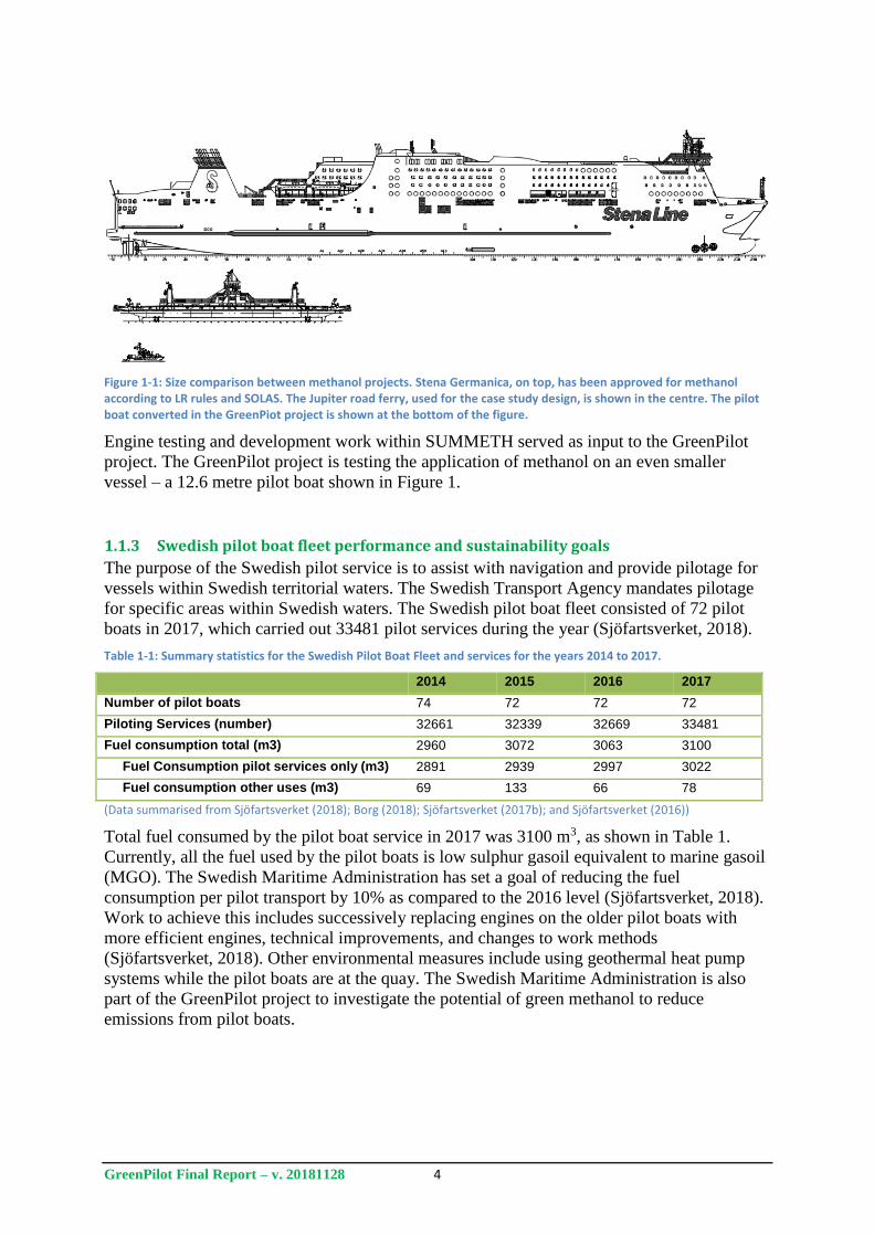
Figure 1-1: Size comparison between methanol projects. Stena Germanica, on top, has been approved for methanol according to LR rules and SOLAS. The Jupiter road ferry, used for the case study design, is shown in the centre. The pilot boat converted in the GreenPiot project is shown at the bottom of the figure.
Engine testing and development work within SUMMETH served as input to the GreenPilot
project. The GreenPilot project is testing the application of methanol on an even smaller
vessel – a 12.6 metre pilot boat shown in Figure 1.
1.1.3 Swedish pilot boat fleet performance and sustainability goals
The purpose of the Swedish pilot service is to assist with navigation and provide pilotage for
vessels within Swedish territorial waters. The Swedish Transport Agency mandates pilotage
for specific areas within Swedish waters. The Swedish pilot boat fleet consisted of 72 pilot
boats in 2017, which carried out 33481 pilot services during the year (Sjöfartsverket, 2018).
Table 1-1: Summary statistics for the Swedish Pilot Boat Fleet and services for the years 2014 to 2017.
2014 2015 2016 2017
Number of pilot boats 74 72 72 72
Piloting Services (number) 32661 32339 32669 33481
Fuel consumption total (m3) 2960 3072 3063 3100
Fuel Consumption pilot services only (m3) 2891 2939 2997 3022
Fuel consumption other uses (m3) 69 133 66 78
(Data summarised from Sjöfartsverket (2018); Borg (2018); Sjöfartsverket (2017b); and Sjöfartsverket (2016))
Total fuel consumed by the pilot boat service in 2017 was 3100 m3, as shown in Table 1.
Currently, all the fuel used by the pilot boats is low sulphur gasoil equivalent to marine gasoil
(MGO). The Swedish Maritime Administration has set a goal of reducing the fuel
consumption per pilot transport by 10% as compared to the 2016 level (Sjöfartsverket, 2018).
Work to achieve this includes successively replacing engines on the older pilot boats with
more efficient engines, technical improvements, and changes to work methods
(Sjöfartsverket, 2018). Other environmental measures include using geothermal heat pump
systems while the pilot boats are at the quay. The Swedish Maritime Administration is also
part of the GreenPilot project to investigate the potential of green methanol to reduce
emissions from pilot boats.
GreenPilot Final Report – v. 20181128 5
1.2 Objectives
The overall goal of the GreenPilot project was to reduce the environmental impact of a pilot
boat through operation on methanol fuel. The specific objectives for achieving this goal
included:
- Evaluating various methanol combustion concepts through laboratory testing, to select
the best engine concept for the pilot boat installation
- Installing an adapted engine and fuel system on board a pilot boat
- Identifying relevant and applicable rules for the design and installation, and using the
experience from the project to contribute to further regulatory development
- Reducing the emissions of CO2, SOx, NOx, PM and BC from the pilot boat operation
- Reducing energy consumption of the pilot boat while at quayside
- Recommending improvements that could be made to other ship systems that have a
negative impact on the environment.
1.3 Scope
The scope of the work included the following:
Adaptation of a suitable pilot boat: An appropriate pilot boat was identified for conversion to
methanol operation. Adaption work included replacing the existing engine with a new engine
that had been modified within the project to run on methanol. Relevant auxiliary systems such
as bunkering, fuel storage and piping, gas and fire detection system, and fire suppression
systems were replaced or adapted to be compatible with methanol operation.
Analysis, evaluation, and development of proposals for applicable rules and regulations for
methanol fuel installations on smaller vessels: Currently, there are no rules in force for the use
of low flashpoint liquid fuels on smaller ships. The project was to identify applicable
solutions and rules to ensure that the current safety levels of the pilot boat operation are
maintained or improved where appropriate. The project results could potentially serve as a
platform for development of official regulations and classification society rules.
Engine Adaptation: A number of methanol engine concepts deemed possible for
implementation on the pilot boat were analysed and the most applicable selected for
installation. The engine was physically adapted and tested before on board installation.
Results from laboratory tests carried out in similar projects such as SUMMETH were utilized
for evaluation and engine adaption/calibration.
System for distribution of methanol: A system and procedure for bunkering methanol to the
pilot boat was to be developed. Fossil-free methanol produced in Sweden was also to be
tested within the project.
Modification of other ship systems to reduce environmental impact: Other ship systems,
separate from the engine, were to be analysed to identify their environmental impact. Possible
methods for reducing these impacts were to be investigated and implemented where possible.
Electrification and fuel cells were part of this additional investigation.
GreenPilot Final Report – v. 20181128 6
2 Methanol conversion of pilot boat
The physical conversion of the 12.6 metre long Swedish Maritime Administration pilot boat,
Pilot 729SE, was based on the existing provisional rules and guidelines for low flashpoint
liquid fuels, including the Draft Technical Provisions for the Safety of Ships Using
Methyl/Ethyl Alcohol as Fuel contained in the IMO’s IGF Code Part A-2 (2016), and the
provisional rules published by the classification societies LR and DNV GL. The aim was to
achieve a safe and reliable design, giving special consideration to the methanol properties that
are significantly different from diesel fuels and using normal risk mitigation practices to
ensure an equivalent level of safety.
The first part of this chapter highlights the properties of methanol that were considered in the
physical design and operational procedures. This is followed by a brief overview of the
regulatory framework relevant for the pilot boat. The main part of the chapter thereafter
describes the conversion work done to the boat that allows for safe operation on methanol.
2.1 Methanol properties considered for ship safety and design From a safety perspective methanol offers some new challenges. In comparison to diesel
fuels, the flashpoint is low, which means that methanol is easily ignited by a spark or open
flame. The lower flashpoint is the largest difference in terms of safety and as a result all
equipment used in areas where methanol leaks can be expected needs to be safe for use in
potentially explosive atmospheres (EX-class equipment). There are also advantages with
methanol from a fire safety perspective - the heat release is lower, no smoke is produced from
methanol combustion, and methanol fires can be extinguished with water.
As methanol is a liquid, conventional fuel tanks are used for storage. Potential spills will also
behave like a liquid and conventional fire suppression methods are used. Methanol is also
soluble in water and is not harmful to the aquatic environment if spilled.
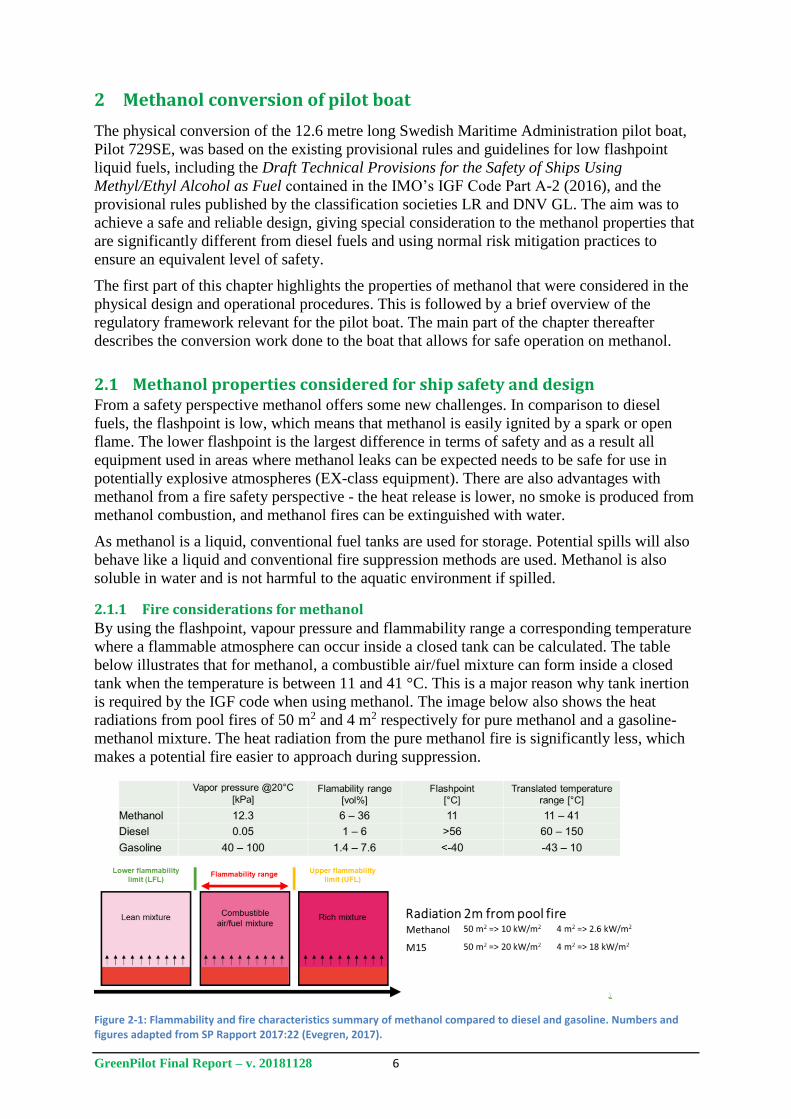
2.1.1 Fire considerations for methanol
By using the flashpoint, vapour pressure and flammability range a corresponding temperature
where a flammable atmosphere can occur inside a closed tank can be calculated. The table
below illustrates that for methanol, a combustible air/fuel mixture can form inside a closed
tank when the temperature is between 11 and 41 °C. This is a major reason why tank inertion
is required by the IGF code when using methanol. The image below also shows the heat
radiations from pool fires of 50 m2 and 4 m2 respectively for pure methanol and a gasoline-
methanol mixture. The heat radiation from the pure methanol fire is significantly less, which
makes a potential fire easier to approach during suppression.
Figure 2-1: Flammability and fire characteristics summary of methanol compared to diesel and gasoline. Numbers and figures adapted from SP Rapport 2017:22 (Evegren, 2017).
GreenPilot Final Report – v. 20181128 7
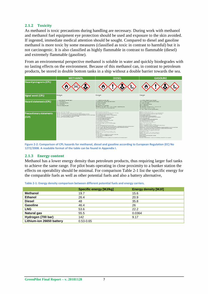
2.1.2 Toxicity
As methanol is toxic precautions during handling are necessary. During work with methanol
and methanol fuel equipment eye protection should be used and exposure to the skin avoided.
If ingested, immediate medical attention should be sought. Compared to diesel and gasoline
methanol is more toxic by some measures (classified as toxic in contrast to harmful) but it is
not carcinogenic. It is also classified as highly flammable in contrast to flammable (diesel)
and extremely flammable (gasoline).
From an environmental perspective methanol is soluble in water and quickly biodegrades with
no lasting effects on the environment. Because of this methanol can, in contrast to petroleum
products, be stored in double bottom tanks in a ship without a double barrier towards the sea.
Figure 2-2: Comparison of CPL hazards for methanol, diesel and gasoline according to European Regulation (EC) No 1272/2008. A readable format of the table can be found in Appendix I.
2.1.3 Energy content
Methanol has a lower energy density than petroleum products, thus requiring larger fuel tanks
to achieve the same range. For pilot boats operating in close proximity to a bunker station the
effects on operability should be minimal. For comparison Table 2-1 list the specific energy for
the comparable fuels as well as other potential fuels and also a battery alternative,
Table 2-1: Energy density comparison between different potential fuels and energy carriers.
Specific energy [MJ/kg] Energy density [MJ/l]
Methanol 19.7 15.6
Ethanol 26.4 20.9
Diesel 48 35.8
Gasoline 46.4 26
LNG 53.6 22.2
Natural gas 55.5 0.0364
Hydrogen (700 bar) 142 9.17
Lithium-ion 26650 battery 0.53-0.65
GreenPilot Final Report – v. 20181128 8
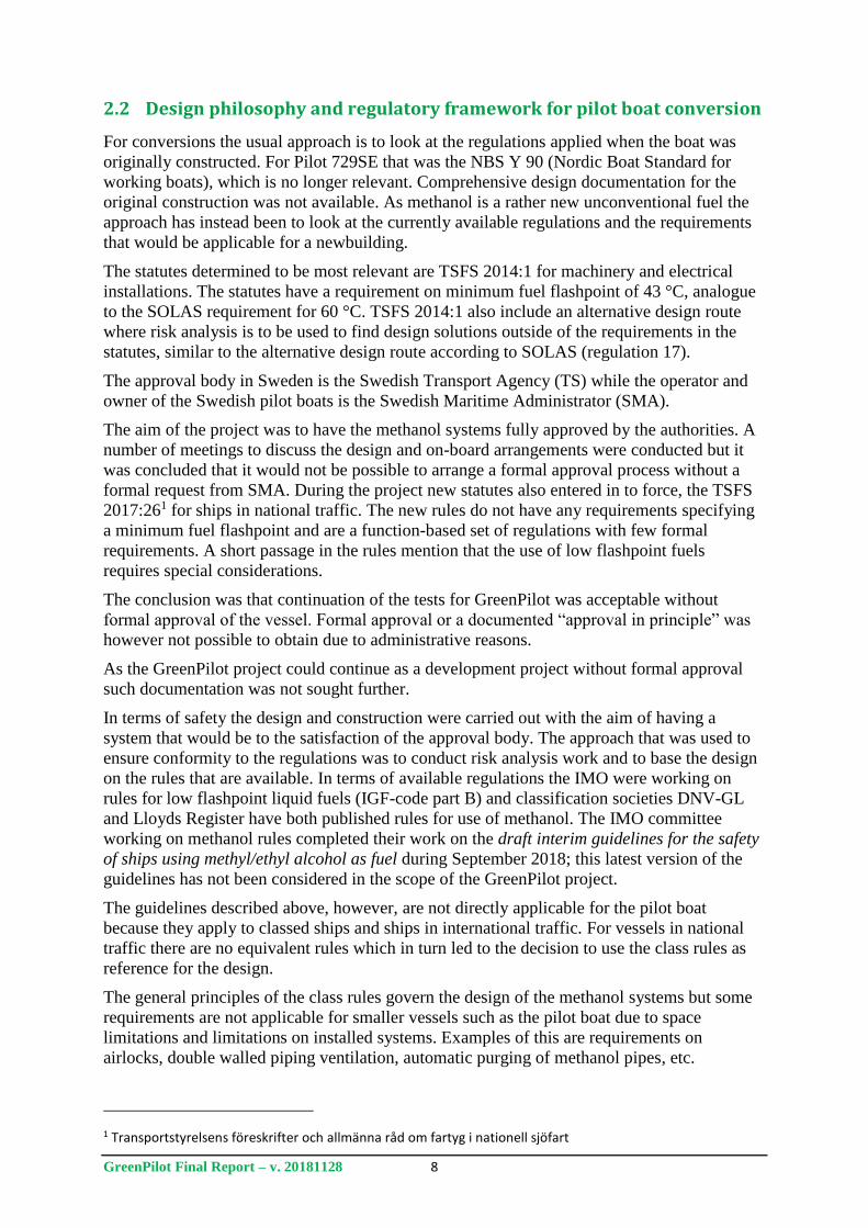
2.2 Design philosophy and regulatory framework for pilot boat conversion
For conversions the usual approach is to look at the regulations applied when the boat was
originally constructed. For Pilot 729SE that was the NBS Y 90 (Nordic Boat Standard for
working boats), which is no longer relevant. Comprehensive design documentation for the
original construction was not available. As methanol is a rather new unconventional fuel the
approach has instead been to look at the currently available regulations and the requirements
that would be applicable for a newbuilding.
The statutes determined to be most relevant are TSFS 2014:1 for machinery and electrical
installations. The statutes have a requirement on minimum fuel flashpoint of 43 °C, analogue
to the SOLAS requirement for 60 °C. TSFS 2014:1 also include an alternative design route
where risk analysis is to be used to find design solutions outside of the requirements in the
statutes, similar to the alternative design route according to SOLAS (regulation 17).
The approval body in Sweden is the Swedish Transport Agency (TS) while the operator and
owner of the Swedish pilot boats is the Swedish Maritime Administrator (SMA).
The aim of the project was to have the methanol systems fully approved by the authorities. A
number of meetings to discuss the design and on-board arrangements were conducted but it
was concluded that it would not be possible to arrange a formal approval process without a
formal request from SMA. During the project new statutes also entered in to force, the TSFS
2017:261 for ships in national traffic. The new rules do not have any requirements specifying
a minimum fuel flashpoint and are a function-based set of regulations with few formal
requirements. A short passage in the rules mention that the use of low flashpoint fuels
requires special considerations.
The conclusion was that continuation of the tests for GreenPilot was acceptable without
formal approval of the vessel. Formal approval or a documented “approval in principle” was
however not possible to obtain due to administrative reasons.
As the GreenPilot project could continue as a development project without formal approval
such documentation was not sought further.
In terms of safety the design and construction were carried out with the aim of having a
system that would be to the satisfaction of the approval body. The approach that was used to
ensure conformity to the regulations was to conduct risk analysis work and to base the design
on the rules that are available. In terms of available regulations the IMO were working on
rules for low flashpoint liquid fuels (IGF-code part B) and classification societies DNV-GL
and Lloyds Register have both published rules for use of methanol. The IMO committee
working on methanol rules completed their work on the draft interim guidelines for the safety
of ships using methyl/ethyl alcohol as fuel during September 2018; this latest version of the
guidelines has not been considered in the scope of the GreenPilot project.
The guidelines described above, however, are not directly applicable for the pilot boat
because they apply to classed ships and ships in international traffic. For vessels in national
traffic there are no equivalent rules which in turn led to the decision to use the class rules as
reference for the design.
The general principles of the class rules govern the design of the methanol systems but some
requirements are not applicable for smaller vessels such as the pilot boat due to space
limitations and limitations on installed systems. Examples of this are requirements on
airlocks, double walled piping ventilation, automatic purging of methanol pipes, etc.
1 Transportstyrelsens föreskrifter och allmänna råd om fartyg i nationell sjöfart

GreenPilot Final Report – v. 20181128 9
The requirements for risk assessment according to the class rules and for alternative design
according to 2014:1 were also somewhat scaled down compared to what would have been
performed on a large ship.
GreenPilot Final Report – v. 20181128 10
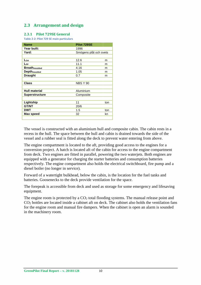
2.3 Arrangement and design
2.3.1 Pilot 729SE General Table 2-2: Pilot 729 SE main particulars
Name Pilot 729SE
Year built: 1996
Yard: Smögens plåt och svets
LOA 12.6 m
LPP 11.1 m
Breathmoulded 4.16 m
Depthmoulded 1.05 m
Draught 0.7 m
Class NBS Y 90
Hull material Aluminium
Superstructure Composite
Lightship 11 ton
GT/NT 20/6
DWT 1.5 ton
Max speed 32 kn
The vessel is constructed with an aluminium hull and composite cabin. The cabin rests in a
recess in the hull. The space between the hull and cabin is drained towards the side of the
vessel and a rubber seal is fitted along the deck to prevent water entering from above.
The engine compartment is located to the aft, providing good access to the engines for a
conversion project. A hatch is located aft of the cabin for access to the engine compartment
from deck. Two engines are fitted in parallel, powering the two waterjets. Both engines are
equipped with a generator for charging the starter batteries and consumption batteries
respectively. The engine compartment also holds the electrical switchboard, fire pump and a
diesel boiler (no longer in service).
Forward of a watertight bulkhead, below the cabin, is the location for the fuel tanks and
batteries. Goosenecks to the deck provide ventilation for the space.
The forepeak is accessible from deck and used as storage for some emergency and lifesaving
equipment.
The engine room is protected by a CO2 total flooding systems. The manual release point and
CO2 bottles are located inside a cabinet aft on deck. The cabinet also holds the ventilation fans
for the engine room and manual fire dampers. When the cabinet is open an alarm is sounded
in the machinery room.
GreenPilot Final Report – v. 20181128 11
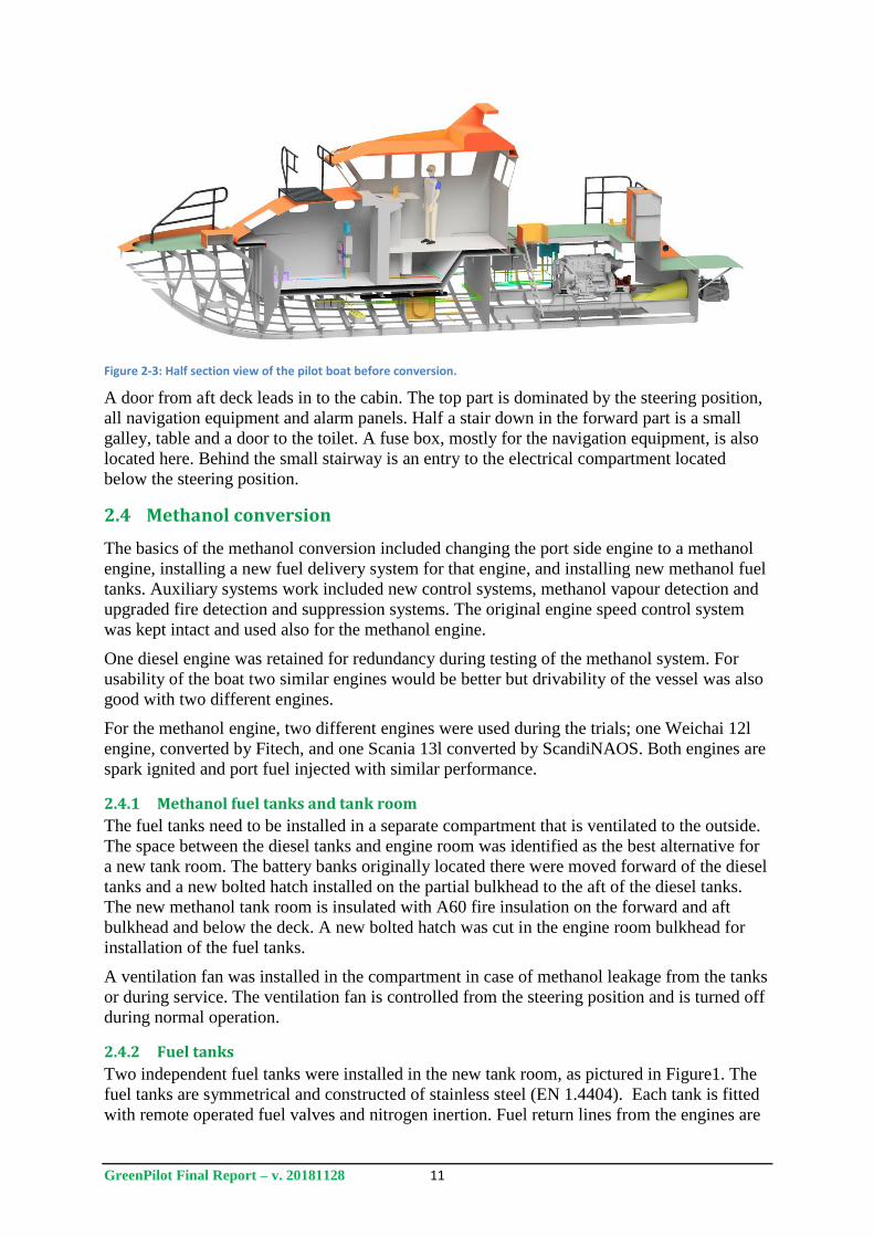
Figure 2-3: Half section view of the pilot boat before conversion.
A door from aft deck leads in to the cabin. The top part is dominated by the steering position,
all navigation equipment and alarm panels. Half a stair down in the forward part is a small
galley, table and a door to the toilet. A fuse box, mostly for the navigation equipment, is also
located here. Behind the small stairway is an entry to the electrical compartment located
below the steering position.
2.4 Methanol conversion
The basics of the methanol conversion included changing the port side engine to a methanol
engine, installing a new fuel delivery system for that engine, and installing new methanol fuel
tanks. Auxiliary systems work included new control systems, methanol vapour detection and
upgraded fire detection and suppression systems. The original engine speed control system
was kept intact and used also for the methanol engine.
One diesel engine was retained for redundancy during testing of the methanol system. For
usability of the boat two similar engines would be better but drivability of the vessel was also
good with two different engines.
For the methanol engine, two different engines were used during the trials; one Weichai 12l
engine, converted by Fitech, and one Scania 13l converted by ScandiNAOS. Both engines are
spark ignited and port fuel injected with similar performance.
2.4.1 Methanol fuel tanks and tank room
The fuel tanks need to be installed in a separate compartment that is ventilated to the outside.
The space between the diesel tanks and engine room was identified as the best alternative for
a new tank room. The battery banks originally located there were moved forward of the diesel
tanks and a new bolted hatch installed on the partial bulkhead to the aft of the diesel tanks.
The new methanol tank room is insulated with A60 fire insulation on the forward and aft
bulkhead and below the deck. A new bolted hatch was cut in the engine room bulkhead for
installation of the fuel tanks.
A ventilation fan was installed in the compartment in case of methanol leakage from the tanks
or during service. The ventilation fan is controlled from the steering position and is turned off
during normal operation.
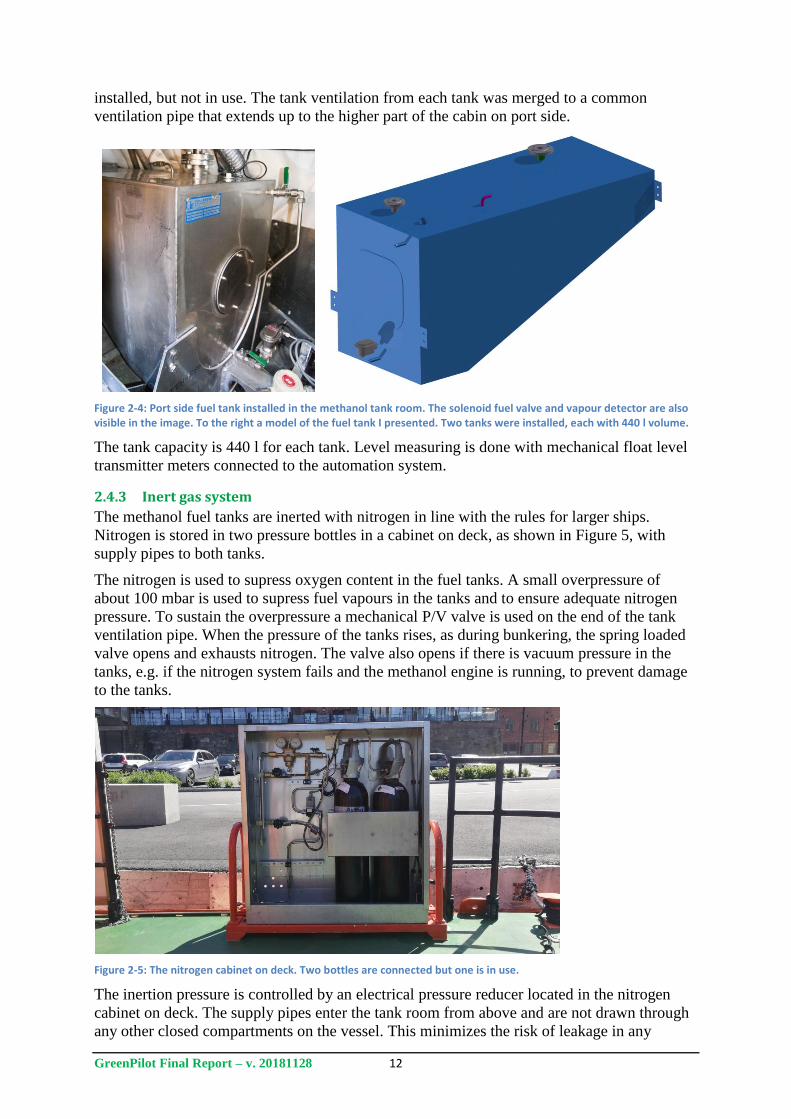
2.4.2 Fuel tanks
Two independent fuel tanks were installed in the new tank room, as pictured in Figure1. The
fuel tanks are symmetrical and constructed of stainless steel (EN 1.4404). Each tank is fitted
with remote operated fuel valves and nitrogen inertion. Fuel return lines from the engines are
GreenPilot Final Report – v. 20181128 12
installed, but not in use. The tank ventilation from each tank was merged to a common
ventilation pipe that extends up to the higher part of the cabin on port side.
Figure 2-4: Port side fuel tank installed in the methanol tank room. The solenoid fuel valve and vapour detector are also visible in the image. To the right a model of the fuel tank I presented. Two tanks were installed, each with 440 l volume.
The tank capacity is 440 l for each tank. Level measuring is done with mechanical float level
transmitter meters connected to the automation system.
2.4.3 Inert gas system
The methanol fuel tanks are inerted with nitrogen in line with the rules for larger ships.
Nitrogen is stored in two pressure bottles in a cabinet on deck, as shown in Figure 5, with
supply pipes to both tanks.
The nitrogen is used to supress oxygen content in the fuel tanks. A small overpressure of
about 100 mbar is used to supress fuel vapours in the tanks and to ensure adequate nitrogen
pressure. To sustain the overpressure a mechanical P/V valve is used on the end of the tank
ventilation pipe. When the pressure of the tanks rises, as during bunkering, the spring loaded
valve opens and exhausts nitrogen. The valve also opens if there is vacuum pressure in the
tanks, e.g. if the nitrogen system fails and the methanol engine is running, to prevent damage
to the tanks.
Figure 2-5: The nitrogen cabinet on deck. Two bottles are connected but one is in use.
The inertion pressure is controlled by an electrical pressure reducer located in the nitrogen
cabinet on deck. The supply pipes enter the tank room from above and are not drawn through
any other closed compartments on the vessel. This minimizes the risk of leakage in any
GreenPilot Final Report – v. 20181128 13
compartment that could lead to oxygen starvation. If nitrogen is stored in a closed
compartment that allows for entering there should be equipment to ensure sufficient oxygen
content in the atmosphere before entering.
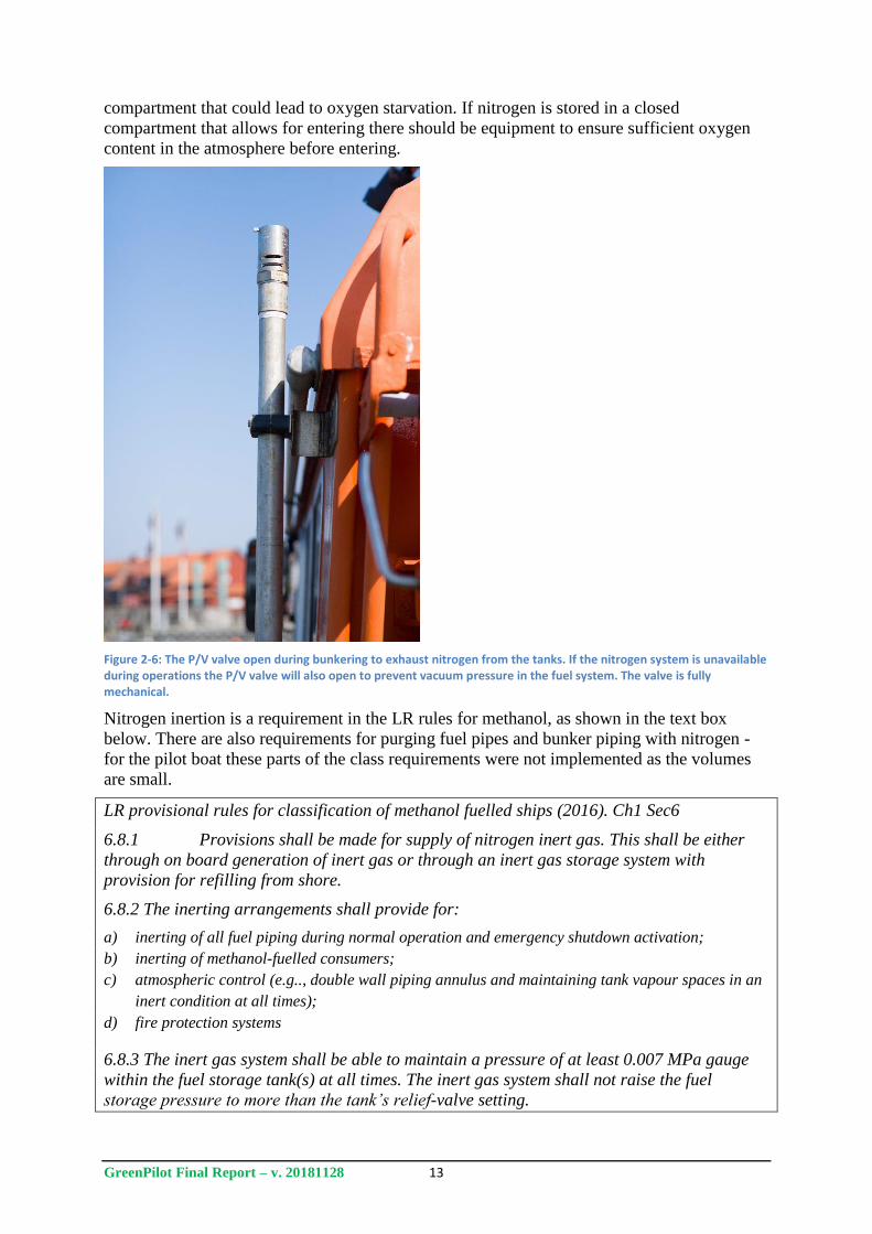
Figure 2-6: The P/V valve open during bunkering to exhaust nitrogen from the tanks. If the nitrogen system is unavailable during operations the P/V valve will also open to prevent vacuum pressure in the fuel system. The valve is fully mechanical.
Nitrogen inertion is a requirement in the LR rules for methanol, as shown in the text box
below. There are also requirements for purging fuel pipes and bunker piping with nitrogen -
for the pilot boat these parts of the class requirements were not implemented as the volumes
are small.
LR provisional rules for classification of methanol fuelled ships (2016). Ch1 Sec6
6.8.1 Provisions shall be made for supply of nitrogen inert gas. This shall be either
through on board generation of inert gas or through an inert gas storage system with
provision for refilling from shore.
6.8.2 The inerting arrangements shall provide for:
a) inerting of all fuel piping during normal operation and emergency shutdown activation;
b) inerting of methanol-fuelled consumers;
c) atmospheric control (e.g.., double wall piping annulus and maintaining tank vapour spaces in an
inert condition at all times);
d) fire protection systems
6.8.3 The inert gas system shall be able to maintain a pressure of at least 0.007 MPa gauge
within the fuel storage tank(s) at all times. The inert gas system shall not raise the fuel
storage pressure to more than the tank’s relief-valve setting.
GreenPilot Final Report – v. 20181128 14
2.4.4 Fuel supply
Mounted on each fuel tank are solenoid fuel valves that allow for remote operation of the fuel
supply. Normally these valves are closed when the engine is not running and they open upon
starting the engine. The pipes from each tank merge to a common supply pipe, this allows for
some overflow between the tanks when both valves are open.
The fuel pipes are single walled inside the tank room. Before penetrating the engine room
bulkhead the supply pipe is double walled to prevent leakage in case of damage to the inner
pipe. Double walled piping is required by the class rules and draft IGF code. The annular
space is not ventilated on the pilot boat application but is used as a secondary boundary.
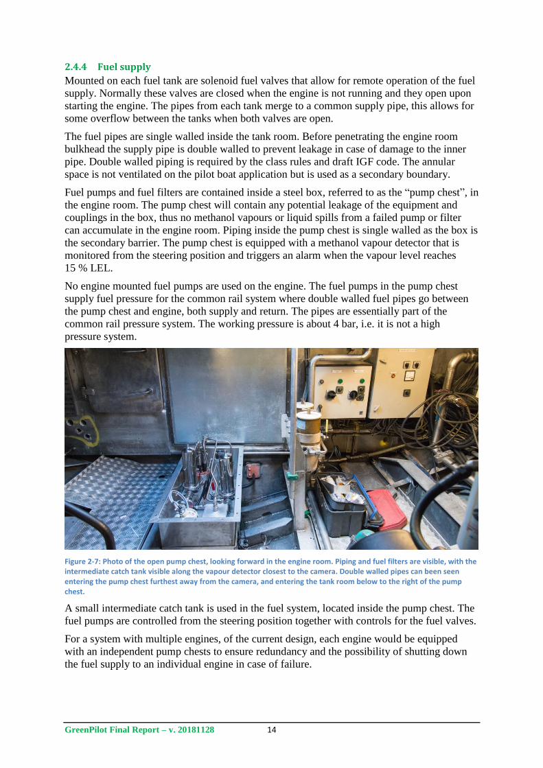
Fuel pumps and fuel filters are contained inside a steel box, referred to as the “pump chest”, in
the engine room. The pump chest will contain any potential leakage of the equipment and
couplings in the box, thus no methanol vapours or liquid spills from a failed pump or filter
can accumulate in the engine room. Piping inside the pump chest is single walled as the box is
the secondary barrier. The pump chest is equipped with a methanol vapour detector that is
monitored from the steering position and triggers an alarm when the vapour level reaches
15 % LEL.
No engine mounted fuel pumps are used on the engine. The fuel pumps in the pump chest
supply fuel pressure for the common rail system where double walled fuel pipes go between
the pump chest and engine, both supply and return. The pipes are essentially part of the
common rail pressure system. The working pressure is about 4 bar, i.e. it is not a high
pressure system.
Figure 2-7: Photo of the open pump chest, looking forward in the engine room. Piping and fuel filters are visible, with the intermediate catch tank visible along the vapour detector closest to the camera. Double walled pipes can been seen entering the pump chest furthest away from the camera, and entering the tank room below to the right of the pump chest.
A small intermediate catch tank is used in the fuel system, located inside the pump chest. The
fuel pumps are controlled from the steering position together with controls for the fuel valves.
For a system with multiple engines, of the current design, each engine would be equipped
with an independent pump chests to ensure redundancy and the possibility of shutting down
the fuel supply to an individual engine in case of failure.
GreenPilot Final Report – v. 20181128 15
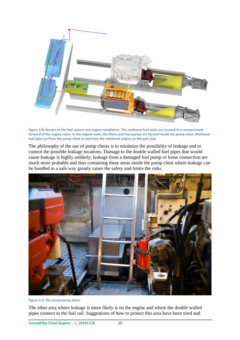
Figure 2-8: Render of the fuel system and engine installation. The methanol fuel tanks are located in a compartment forward of the engine room. In the engine room, the filters and fuel pumps are located inside the pump chest. Methanol fuel pipes go from the pump chest to and from the methanol engine on the port side.
The philosophy of the use of pump chests is to minimize the possibility of leakage and to
control the possible leakage locations. Damage to the double walled fuel pipes that would
cause leakage is highly unlikely; leakage from a damaged fuel pump or loose connection are
much more probable and thus containing these areas inside the pump chest where leakage can
be handled in a safe way greatly raises the safety and limits the risks.
Figure 2-9: The closed pump chest.
The other area where leakage is more likely is on the engine and where the double walled
pipes connect to the fuel rail. Suggestions of how to protect this area have been tried and
GreenPilot Final Report – v. 20181128 16
evaluated but no protection is currently in use. During testing no incidents of leakage from the
pipe connection or fuel injector connections to the fuel rail have been detected.
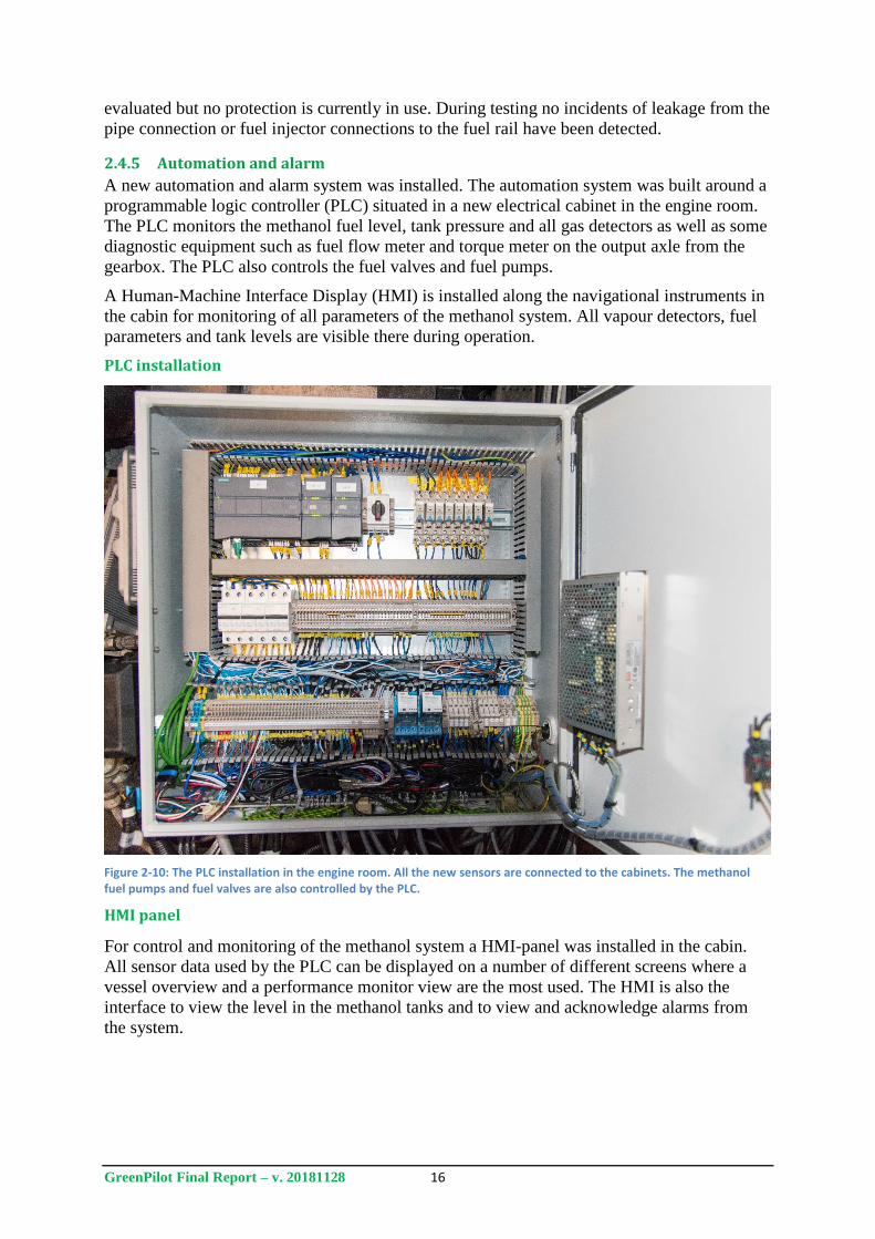
2.4.5 Automation and alarm
A new automation and alarm system was installed. The automation system was built around a
programmable logic controller (PLC) situated in a new electrical cabinet in the engine room.
The PLC monitors the methanol fuel level, tank pressure and all gas detectors as well as some
diagnostic equipment such as fuel flow meter and torque meter on the output axle from the
gearbox. The PLC also controls the fuel valves and fuel pumps.
A Human-Machine Interface Display (HMI) is installed along the navigational instruments in
the cabin for monitoring of all parameters of the methanol system. All vapour detectors, fuel
parameters and tank levels are visible there during operation.
PLC installation
Figure 2-10: The PLC installation in the engine room. All the new sensors are connected to the cabinets. The methanol fuel pumps and fuel valves are also controlled by the PLC.
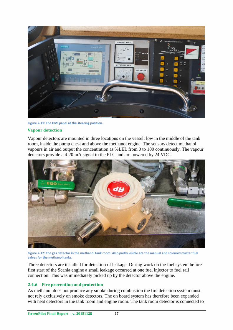
HMI panel
For control and monitoring of the methanol system a HMI-panel was installed in the cabin.
All sensor data used by the PLC can be displayed on a number of different screens where a
vessel overview and a performance monitor view are the most used. The HMI is also the
interface to view the level in the methanol tanks and to view and acknowledge alarms from
the system.
GreenPilot Final Report – v. 20181128 17
Figure 2-11: The HMI panel at the steering position.
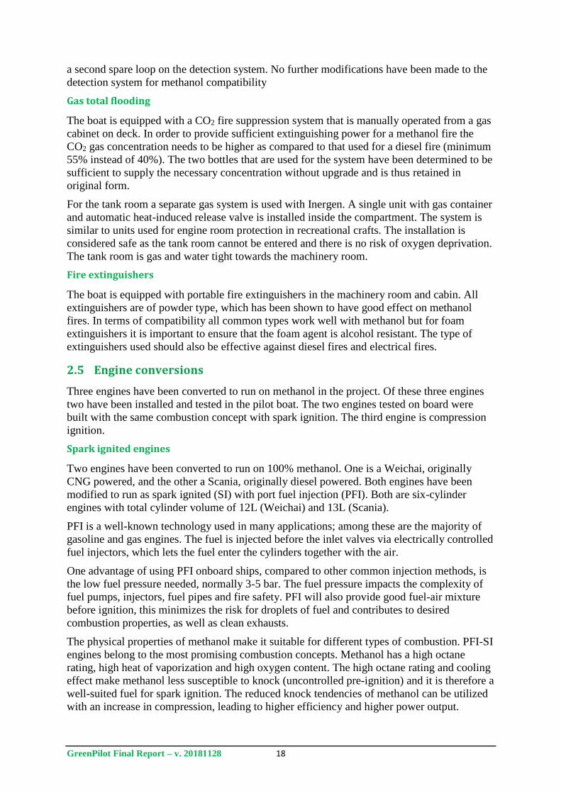
Vapour detection
Vapour detectors are mounted in three locations on the vessel: low in the middle of the tank
room, inside the pump chest and above the methanol engine. The sensors detect methanol
vapours in air and output the concentration as %LEL from 0 to 100 continuously. The vapour
detectors provide a 4-20 mA signal to the PLC and are powered by 24 VDC.
Figure 2-12: The gas detector in the methanol tank room. Also partly visible are the manual and solenoid master fuel valves for the methanol tanks.
Three detectors are installed for detection of leakage. During work on the fuel system before
first start of the Scania engine a small leakage occurred at one fuel injector to fuel rail
connection. This was immediately picked up by the detector above the engine.
2.4.6 Fire prevention and protection
As methanol does not produce any smoke during combustion the fire detection system must
not rely exclusively on smoke detectors. The on board system has therefore been expanded
with heat detectors in the tank room and engine room. The tank room detector is connected to
GreenPilot Final Report – v. 20181128 18
a second spare loop on the detection system. No further modifications have been made to the
detection system for methanol compatibility
Gas total flooding
The boat is equipped with a CO2 fire suppression system that is manually operated from a gas
cabinet on deck. In order to provide sufficient extinguishing power for a methanol fire the
CO2 gas concentration needs to be higher as compared to that used for a diesel fire (minimum
55% instead of 40%). The two bottles that are used for the system have been determined to be
sufficient to supply the necessary concentration without upgrade and is thus retained in
original form.
For the tank room a separate gas system is used with Inergen. A single unit with gas container
and automatic heat-induced release valve is installed inside the compartment. The system is
similar to units used for engine room protection in recreational crafts. The installation is
considered safe as the tank room cannot be entered and there is no risk of oxygen deprivation.
The tank room is gas and water tight towards the machinery room.
Fire extinguishers
The boat is equipped with portable fire extinguishers in the machinery room and cabin. All
extinguishers are of powder type, which has been shown to have good effect on methanol
fires. In terms of compatibility all common types work well with methanol but for foam
extinguishers it is important to ensure that the foam agent is alcohol resistant. The type of
extinguishers used should also be effective against diesel fires and electrical fires.
2.5 Engine conversions
Three engines have been converted to run on methanol in the project. Of these three engines
two have been installed and tested in the pilot boat. The two engines tested on board were
built with the same combustion concept with spark ignition. The third engine is compression
ignition.
Spark ignited engines
Two engines have been converted to run on 100% methanol. One is a Weichai, originally
CNG powered, and the other a Scania, originally diesel powered. Both engines have been
modified to run as spark ignited (SI) with port fuel injection (PFI). Both are six-cylinder
engines with total cylinder volume of 12L (Weichai) and 13L (Scania).
PFI is a well-known technology used in many applications; among these are the majority of
gasoline and gas engines. The fuel is injected before the inlet valves via electrically controlled
fuel injectors, which lets the fuel enter the cylinders together with the air.
One advantage of using PFI onboard ships, compared to other common injection methods, is
the low fuel pressure needed, normally 3-5 bar. The fuel pressure impacts the complexity of
fuel pumps, injectors, fuel pipes and fire safety. PFI will also provide good fuel-air mixture
before ignition, this minimizes the risk for droplets of fuel and contributes to desired
combustion properties, as well as clean exhausts.
The physical properties of methanol make it suitable for different types of combustion. PFI-SI
engines belong to the most promising combustion concepts. Methanol has a high octane
rating, high heat of vaporization and high oxygen content. The high octane rating and cooling
effect make methanol less susceptible to knock (uncontrolled pre-ignition) and it is therefore a
well-suited fuel for spark ignition. The reduced knock tendencies of methanol can be utilized
with an increase in compression, leading to higher efficiency and higher power output.
GreenPilot Final Report – v. 20181128 19
Methanol is less likely to form soot emissions because it is a simple molecule with one carbon
atom, and it contains oxygen. The cooling effect from fuel vaporization will reduce emissions
of NOx.
Spark ignited engines can run stoichiometric with a three-way catalyst or lean burn with an
oxidation catalyst that reduces emissions.
Methanol is a single-component fuel (one type of molecule) with a specific vapor pressure
and boiling point; this is not the case for gasoline, diesel and most gas fuels where variations
in the chemical composition require higher tolerance and therefore less optimized engines.
In a cold engine it can be difficult to vaporize enough fuel to reach an ignitable mixture.
Potentially this could make low-temperature cold starts difficult.
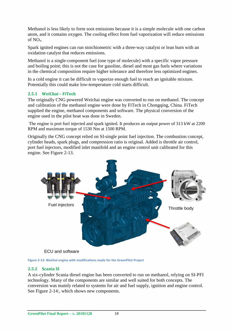
2.5.1 WeiChai – FiTech
The originally CNG powered Weichai engine was converted to run on methanol. The concept
and calibration of the methanol engine were done by FiTech in Chongqing, China. FiTech
supplied the engine, methanol components and software. The physical conversion of the
engine used in the pilot boat was done in Sweden.
The engine is port fuel injected and spark ignited. It produces an output power of 313 kW at 2200
RPM and maximum torque of 1530 Nm at 1500 RPM.
Originally the CNG concept relied on SI-single point fuel injection. The combustion concept,
cylinder heads, spark plugs, and compression ratio is original. Added is throttle air control,
port fuel injectors, modified inlet manifold and an engine control unit calibrated for this
engine. See Figure 2-13.
Figure 2-13: Weichai engine with modifications made for the GreenPilot Project
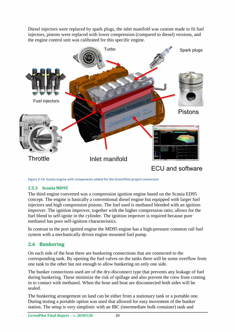
2.5.2 Scania SI
A six-cylinder Scania diesel engine has been converted to run on methanol, relying on SI-PFI
technology. Many of the components are similar and well suited for both concepts. The
conversion was mainly related to systems for air and fuel supply, ignition and engine control.
See Figure 2-14:, which shows new components.
Fuel injectors Throttle body
ECU and software
GreenPilot Final Report – v. 20181128 20
Diesel injectors were replaced by spark plugs, the inlet manifold was custom made to fit fuel
injectors, pistons were replaced with lower compression (compared to diesel) versions, and
the engine control unit was calibrated for this specific engine.
Figure 2-14: Scania engine with components added for the GreenPilot project conversion
2.5.3 Scania MD95
The third engine converted was a compression ignition engine based on the Scania ED95
concept. The engine is basically a conventional diesel engine but equipped with larger fuel
injectors and high compression pistons. The fuel used is methanol blended with an ignition
improver. The ignition improver, together with the higher compression ratio, allows for the
fuel blend to self-ignite in the cylinder. The ignition improver is required because pure
methanol has poor self-ignition characteristics.
In contrast to the port ignited engine the MD95 engine has a high-pressure common rail fuel
system with a mechanically driven engine mounted fuel pump.
2.6 Bunkering
On each side of the boat there are bunkering connections that are connected to the
corresponding tank. By opening the fuel valves on the tanks there will be some overflow from
one tank to the other but not enough to allow bunkering on only one side.
The bunker connections used are of the dry-disconnect type that prevents any leakage of fuel
during bunkering. These minimize the risk of spillage and also prevent the crew from coming
in to contact with methanol. When the hose and boat are disconnected both sides will be
sealed.
The bunkering arrangement on land can be either from a stationary tank or a portable one.
During testing a portable option was used that allowed for easy movement of the bunker
station. The setup is very simplistic with an IBC (intermediate bulk container) tank and
Fuel injectors
Throttle
ECU and software
Spark plugs
Inlet manifold
Turbo
Pistons
GreenPilot Final Report – v. 20181128 21
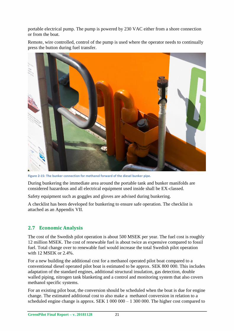
portable electrical pump. The pump is powered by 230 VAC either from a shore connection
or from the boat.
Remote, wire controlled, control of the pump is used where the operator needs to continually
press the button during fuel transfer.
Figure 2-15: The bunker connection for methanol forward of the diesel bunker pipe.
During bunkering the immediate area around the portable tank and bunker manifolds are
considered hazardous and all electrical equipment used inside shall be EX-classed.
Safety equipment such as goggles and gloves are advised during bunkering.
A checklist has been developed for bunkering to ensure safe operation. The checklist is
attached as an Appendix VII.
2.7 Economic Analysis
The cost of the Swedish pilot operation is about 500 MSEK per year. The fuel cost is roughly
12 million MSEK. The cost of renewable fuel is about twice as expensive compared to fossil
fuel. Total change over to renewable fuel would increase the total Swedish pilot operation
with 12 MSEK or 2.4%.
For a new building the additional cost for a methanol operated pilot boat compared to a
conventional diesel operated pilot boat is estimated to be approx. SEK 800 000. This includes
adaptation of the standard engines, additional structural insulation, gas detection, double
walled piping, nitrogen tank blanketing and a control and monitoring system that also covers
methanol specific systems.
For an existing pilot boat, the conversion should be scheduled when the boat is due for engine
change. The estimated additional cost to also make a methanol conversion in relation to a
scheduled engine change is approx. SEK 1 000 000 – 1 300 000. The higher cost compared to

GreenPilot Final Report – v. 20181128 22
new building is due to structural works related to modification of fuel tank, tank rooms,
ventilation, replacement of existing piping and insulation.
GreenPilot Final Report – v. 20181128 23
3 Hazard Identification and Safety Assessment
Work carried out to assess the safety of the methanol system installed on board pilot boat 729,
to minimise risks during testing of the system, and to identify potential safety issues, included
the following:
Preliminary Hazard Identification sessions carried out by Lloyds Register in Copenhagen
Hazard review meeting with project team members and the Swedish Transport Agency
Preparation of a Hazardous Area Plan for pilot boat 729
Review of previous accident and incident data for Swedish pilot boats.
These are described in more detail in the following sub-sections.
3.1 Hazard Identification
A preliminary hazard identification study was conducted for the GreenPilot methanol
conversion design prior to the actual conversion of the vessel. At the time of the hazard
identification workshops the design of the systems was to a large degree completed, which
allowed for a practical review and evaluation of the proposed design to find areas for
improvement. This section is mainly a description of the formal preliminary hazard
identification study done together with Lloyds Register (LR) in Copenhagen. During the
design phase informal hazard and safety assessment discussions were an integral part of the
work, and were conducted as part of evaluation of different design proposals based on
previous experience of methanol systems design for the Stena Scanrail (SPIRETH project)
and Stena Germanica conversion project.
The aim of the risk analysis was to ensure that the proposed design would be at least as safe as
a conventional design. The rules referred to for the requirements were the LR Provision Rules
for the Classification of Methanol Fuelled Ships. The pilot boat is not subject to class rules
and is significantly smaller than classed ships – this has a large impact on which requirements
are feasible. Although not all class rules could be applied, they were used as the basis of the
study.
The preliminary hazard identification study was arranged as a workshop at the LR offices in
Copenhagen and was attended by experts from LR and the design team from ScandiNAOS.
All of the methanol and auxiliary systems were reviewed together with a basic operational
profile for the boat where general risks with methanol use were addressed. The workshop was
conducted during two separate occasions where some of the remarks from the first day were
addressed before the second session took place.
In order to systematically work through the design a number of nodes were used to encourage
discussions around the different systems. The nodes are presented in Table 3-1.
Table 3-1: Preliminary HAZID Study Nodes.
Nodes
Equipment and Location Methanol tank room and fire insulation
General arrangement
Methanol pump chest
Methanol piping
Operational modes Sailing, normal operation
Sailing, heavy weather
GreenPilot Final Report – v. 20181128 24
Sailing, methanol systems not working
Bunkering
Failures Methanol leakage in tank, pipe or valves
Fire
3.1.1 Conclusions and comments
The hazard identification work resulted in a Hazid Study report from LR where the
GreenPilot boat methanol system was reviewed. The full report is attached as Appendix VI.
The key items identified in the study report are discussed below.
Location of the p/v valve for the methanol tank should be carefully considered.
During the design process the proposed location of the P/V (pressure/vacuum) valve was
changed a number of times. The first suggestion was a mast on aft deck, inspired by the
requirements in the rules, that would be separate from the cabin. This solution offered the best
possibility to be in line with the rules but introduced a large risk of being damaged, especially
during operation in heavy weather when receiving or leaving a pilot on another ship.
The final solution was to arrange the valve on port side of the cabin, forward of the bunker
manifold.
During normal operation the valve will remain closed. During bunkering it will ventilate
nitrogen from the fuel tanks. In case of failure of the nitrogen system a vacuum pressure
inside the tanks will build until the valve opens at which time air will be allowed in to the
tanks to restore atmospheric pressure.
Ventilation and ex safe requirements for the pump chest need to be further considered.
Ventilation of the pump chest is another area where the design has iterated during the process.
The final decision was to have no active ventilation of the pump chest. Instead two valves are
fitted to the box in order to drain any possible methanol leakage.
Ventilation requirement in the methanol tank room to be confirmed.
The tank room is equipped with an in-line fan for extraction of air from the tank room. Air is
drawn from a low point in the middle of the room and exhausted on starboard side of the
vessel. The fan can be turned on from the control panel in the cabin. During normal operation
the fan is not running and the pipe allows for some natural ventilation of the compartment.
If the methanol detector inside the tank room indicates methanol vapours the fan is used to
ventilate the compartment. The fan is spark resistant according to recreational craft ISO-
standards.
Bunkering operations need to be further considered.
A bunkering checklist has been developed and is attached in the report as an appendix.
The missing double block and bleed arrangement to be further considered.
Double block and bleed is not a requirement for methanol installations. The concept is used
for LNG and gaseous fuels where fuel can be trapped between two closed valves and create
high pressures when evaporating. This is not relevant for fuels that are liquid at ambient
temperature and pressure.
The outer pipes of the methanol double pipes to be further considered, as they are not
ventilated or pressurized.
Double walled pipes are used in order to minimize the risk of methanol leakage. The annular
space is not ventilated but open towards the pump chest. In case of leakage of the inner pipe
GreenPilot Final Report – v. 20181128 25
methanol will be drained to the pump chest where the methanol detector will indicate leakage.
The pump chest is considered safe and leakage will not result in an immediate danger.
All existing installations need to be included in the modification drawings, as pipes and
cables passing through the methanol tank room were not shown on the current drawings.
The issue relates to the arrangement of the tank room between the engine compartment and
the cabin. As the tank room is located forward of the engine compartment all cables and pipes
pass right through the compartment. This includes communication interfaces as well as
electrical power cables. All cables are of fire retardant material and no connections or joints
are located inside the tank room. The cables are not cause for any foreseeable risk but would
preferably be routed differently if the possibility existed.
3.2 Hazard review meeting prior to sea trials
After conversion work was completed on the vessel, a meeting and on-board review was
carried out prior to sea trials. As the vessel was a demonstration platform only and the engine
had not been adapted for commercial use, the full system did not undergo formal approval and
certification for the pilot testing.
The meeting attendees included the ScandiNAOS design team, a representative from project
partner SSPA, a Swedish Transport Agency representative, and a Swedish Maritime
Administration representative. The meeting took place on 20170406 at ScandiNAOS offices
and included a visit on board the pilot boat to review the installed system. The latest version
of the design was presented and the key items identified in the Preliminary Hazard
Identification Study report as described above were reviewed. Items discussed included the
location of the p/v valve, location of detectors (heat, smoke, and methanol detectors),
ventilation, and the pump chest, among other issues.
3.3 Hazardous area plan
A hazardous area plan is used to identify areas where flammable liquids, vapours or gas can
be expected to exist, and to restrict access and ignition sources as appropriate for the level of
hazard. A hazardous area plan for the pilot boat was developed according to the general
principles from the LR rules for methanol fuelled ships. The hazardous areas definition and
the prescribed hazardous zones around points such as ventilation outlets is one of the class
rules which is the least suitable for use on smaller vessels. It is neither possible nor reasonable
to use the large safety zones prescribed in the rules and it is important to remember that the
rules were developed for ship applications where the methanol fuel tanks alone are many
times larger than a smaller boat. Thus, the possible worst case scenario of flammable vapour
volume will also be very different.
The general idea of hazardous area classification is, however, is still relevant to smaller
vessels. The class rules and IGF code define the areas similarly. The DNV-GL rules have a
good definition as quoted in Table 3-2.
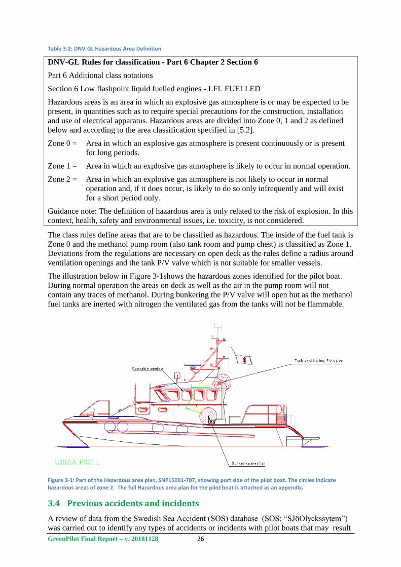
GreenPilot Final Report – v. 20181128 26
Table 3-2: DNV-GL Hazardous Area Definition
DNV-GL Rules for classification - Part 6 Chapter 2 Section 6
Part 6 Additional class notations
Section 6 Low flashpoint liquid fuelled engines - LFL FUELLED
Hazardous areas is an area in which an explosive gas atmosphere is or may be expected to be
present, in quantities such as to require special precautions for the construction, installation
and use of electrical apparatus. Hazardous areas are divided into Zone 0, 1 and 2 as defined
below and according to the area classification specified in [5.2].
Zone 0 = Area in which an explosive gas atmosphere is present continuously or is present
for long periods.
Zone 1 = Area in which an explosive gas atmosphere is likely to occur in normal operation.
Zone 2 = Area in which an explosive gas atmosphere is not likely to occur in normal
operation and, if it does occur, is likely to do so only infrequently and will exist
for a short period only.
Guidance note: The definition of hazardous area is only related to the risk of explosion. In this
context, health, safety and environmental issues, i.e. toxicity, is not considered.
The class rules define areas that are to be classified as hazardous. The inside of the fuel tank is
Zone 0 and the methanol pump room (also tank room and pump chest) is classified as Zone 1.
Deviations from the regulations are necessary on open deck as the rules define a radius around
ventilation openings and the tank P/V valve which is not suitable for smaller vessels.
The illustration below in Figure 3-1shows the hazardous zones identified for the pilot boat.
During normal operation the areas on deck as well as the air in the pump room will not
contain any traces of methanol. During bunkering the P/V valve will open but as the methanol
fuel tanks are inerted with nitrogen the ventilated gas from the tanks will not be flammable.
Figure 3-1: Part of the Hazardous area plan, SNP15091-707, showing port side of the pilot boat. The circles indicate hazardous areas of zone 2. The full Hazardous area plan for the pilot boat is attached as an appendix.
3.4 Previous accidents and incidents
A review of data from the Swedish Sea Accident (SOS) database (SOS: “SJöOlyckssytem”)
was carried out to identify any types of accidents or incidents with pilot boats that may result
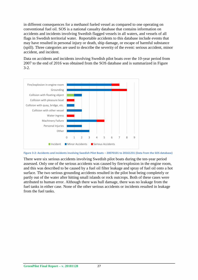
GreenPilot Final Report – v. 20181128 27
in different consequences for a methanol fueled vessel as compared to one operating on
conventional fuel oil. SOS is a national casualty database that contains information on
accidents and incidents involving Swedish flagged vessels in all waters, and vessels of all
flags in Swedish territorial water. Reportable accidents to this database include events that
may have resulted in personal injury or death, ship damage, or escape of harmful substance
(spill). Three categories are used to describe the severity of the event: serious accident, minor
accident, and incident.
Data on accidents and incidents involving Swedish pilot boats over the 10-year period from
2007 to the end of 2016 was obtained from the SOS database and is summarized in Figure
3-2.
Figure 3-2: Accidents and incidents involving Swedish Pilot Boats – 20070101 to 20161231 (Data from the SOS database)
There were six serious accidents involving Swedish pilot boats during the ten-year period
assessed. Only one of the serious accidents was caused by fire/explosion in the engine room,
and this was described to be caused by a fuel oil filter leakage and spray of fuel oil onto a hot
surface. The two serious grounding accidents resulted in the pilot boat being completely or
partly out of the water after hitting small islands or rock outcrops. Both of these cases were
attributed to human error. Although there was hull damage, there was no leakage from the
fuel tanks in either case. None of the other serious accidents or incidents resulted in leakage
from the fuel tanks.
0 1 2 3 4 5 6 7 8 9
Other
Personal Injuries
Machinery Failure
Water ingress
Collision with other vessel
Collision with quay, bridge, etc.
Collision with pleasure boat
Collision with floating object
Grounding
Fire/explosion in engine room
Incident Minor Accidents Serious Accidents
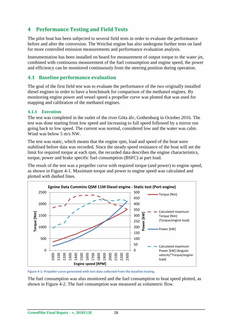
GreenPilot Final Report – v. 20181128 28
4 Performance Testing and Field Tests
The pilot boat has been subjected to several field tests in order to evaluate the performance
before and after the conversion. The Weichai engine has also undergone further tests on land
for more controlled emission measurements and performance evaluation analysis.
Instrumentation has been installed on board for measurement of output torque to the water jet,
combined with continuous measurement of the fuel consumption and engine speed, the power
and efficiency can be monitored continuously from the steering position during operation.
4.1 Baseline performance evaluation
The goal of the first field test was to evaluate the performance of the two originally installed
diesel engines in order to have a benchmark for comparison of the methanol engines. By
monitoring engine power and vessel speed a propeller curve was plotted that was used for
mapping and calibration of the methanol engines.
4.1.1 Execution
The test was completed in the outlet of the river Göta älv, Gothenburg in October 2016. The
test was done starting from low speed and increasing to full speed followed by a mirror run
going back to low speed. The current was normal, considered low and the water was calm.
Wind was below 5 m/s NW.
The test was static, which means that the engine rpm, load and speed of the boat were
stabilised before data was recorded. Since the steady speed resistance of the boat will set the
limit for required torque at each rpm, the recorded data describes the engine characteristics,
torque, power and brake specific fuel consumption (BSFC) at part load.
The result of the test was a propeller curve with required torque (and power) to engine speed,
as shown in Figure 4-1. Maximum torque and power to engine speed was calculated and
plotted with dashed lines.
Figure 4-1: Propeller curve generated with test data collected from the baseline testing.
The fuel consumption was also monitored and the fuel consumption to boat speed plotted, as
shown in Figure 4-2. The fuel consumption was measured as volumetric flow.
0
50
100
150
200
250
300
350
400
450
500
0
500
1000
1500
2000
2500
10
00
11
00
12
00
13
00
14
00
15
00
16
00
17
00
18
00
19
00
20
00
21
00
22
00
23
00
Po
we
r [k
W]
Torq
ue
[N
m]
Engine speed [RPM]
Egnine Data Cummins QSM 11M Diesel engine - Static test (Port engine)
Torque [Nm]
Calculated maximumTorque [Nm](Torque/engine load)
Power [kW]
Calculated maximumPower [kW] (Angularvelocity*Torque/engineload)
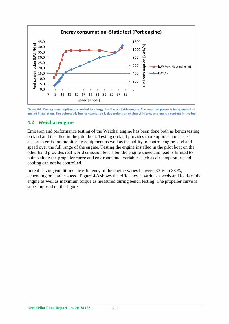
GreenPilot Final Report – v. 20181128 29
Figure 4-2: Energy consumption, converted to energy, for the port side engine. The required power is independent of engine installation. The volumetric fuel consumption is dependent on engine efficiency and energy content in the fuel.
4.2 Weichai engine
Emission and performance testing of the Weichai engine has been done both as bench testing
on land and installed in the pilot boat. Testing on land provides more options and easier
access to emission monitoring equipment as well as the ability to control engine load and
speed over the full range of the engine. Testing the engine installed in the pilot boat on the
other hand provides real world emission levels but the engine speed and load is limited to
points along the propeller curve and environmental variables such as air temperature and
cooling can not be controlled.
In real driving conditions the efficiency of the engine varies between 33 % to 38 %,
depending on engine speed. Figure 4-3 shows the efficiency at various speeds and loads of the
engine as well as maximum torque as measured during bench testing. The propeller curve is
superimposed on the figure.
0
200
400
600
800
1000
1200
0,0
5,0
10,0
15,0
20,0
25,0
30,0
35,0
40,0
45,0
7 9 11 13 15 17 19 21 23 25 27 29
Fue
l co
nsu
mp
tio
n [
kWh
/h]
Fue
l co
nsu
mp
tio
n [
kWh
/Nm
]
Speed [Knots]
Energy consumption -Static test (Port engine)
kWh/nm(Nautical mile)
kWh/h
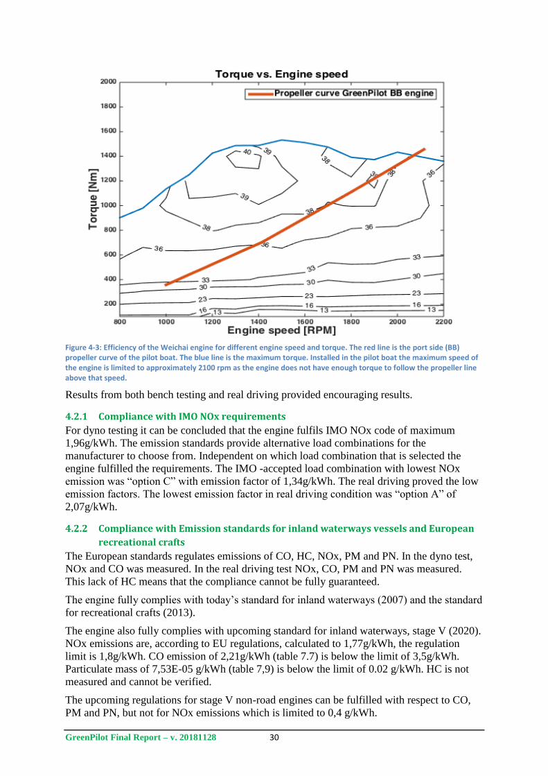
GreenPilot Final Report – v. 20181128 30
Figure 4-3: Efficiency of the Weichai engine for different engine speed and torque. The red line is the port side (BB) propeller curve of the pilot boat. The blue line is the maximum torque. Installed in the pilot boat the maximum speed of the engine is limited to approximately 2100 rpm as the engine does not have enough torque to follow the propeller line above that speed.
Results from both bench testing and real driving provided encouraging results.
4.2.1 Compliance with IMO NOx requirements
For dyno testing it can be concluded that the engine fulfils IMO NOx code of maximum
1,96g/kWh. The emission standards provide alternative load combinations for the
manufacturer to choose from. Independent on which load combination that is selected the
engine fulfilled the requirements. The IMO -accepted load combination with lowest NOx
emission was “option C” with emission factor of 1,34g/kWh. The real driving proved the low
emission factors. The lowest emission factor in real driving condition was “option A” of
2,07g/kWh.
4.2.2 Compliance with Emission standards for inland waterways vessels and European
recreational crafts
The European standards regulates emissions of CO, HC, NOx, PM and PN. In the dyno test,
NOx and CO was measured. In the real driving test NOx, CO, PM and PN was measured.
This lack of HC means that the compliance cannot be fully guaranteed.
The engine fully complies with today’s standard for inland waterways (2007) and the standard
for recreational crafts (2013).
The engine also fully complies with upcoming standard for inland waterways, stage V (2020).
NOx emissions are, according to EU regulations, calculated to 1,77g/kWh, the regulation
limit is 1,8g/kWh. CO emission of 2,21g/kWh (table 7.7) is below the limit of 3,5g/kWh.
Particulate mass of 7,53E-05 g/kWh (table 7,9) is below the limit of 0.02 g/kWh. HC is not
measured and cannot be verified.
The upcoming regulations for stage V non-road engines can be fulfilled with respect to CO,
PM and PN, but not for NOx emissions which is limited to 0,4 g/kWh.
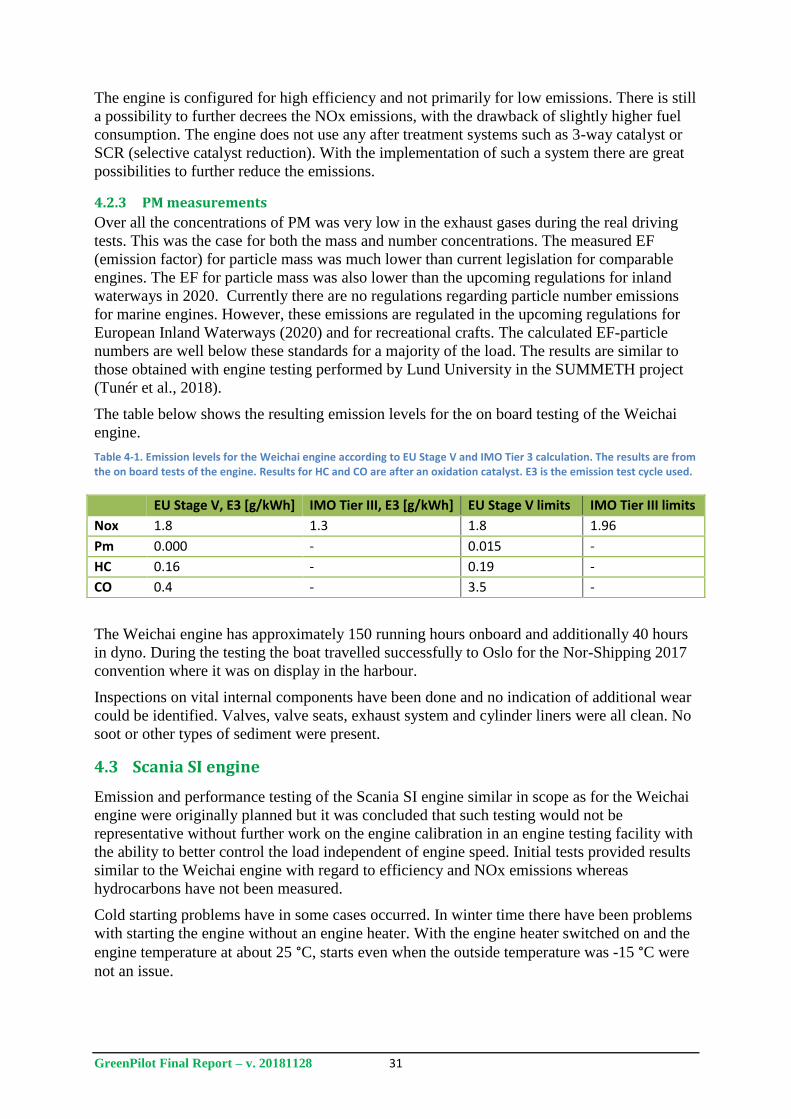
GreenPilot Final Report – v. 20181128 31
The engine is configured for high efficiency and not primarily for low emissions. There is still
a possibility to further decrees the NOx emissions, with the drawback of slightly higher fuel
consumption. The engine does not use any after treatment systems such as 3-way catalyst or
SCR (selective catalyst reduction). With the implementation of such a system there are great
possibilities to further reduce the emissions.
4.2.3 PM measurements
Over all the concentrations of PM was very low in the exhaust gases during the real driving
tests. This was the case for both the mass and number concentrations. The measured EF
(emission factor) for particle mass was much lower than current legislation for comparable
engines. The EF for particle mass was also lower than the upcoming regulations for inland
waterways in 2020. Currently there are no regulations regarding particle number emissions
for marine engines. However, these emissions are regulated in the upcoming regulations for
European Inland Waterways (2020) and for recreational crafts. The calculated EF-particle
numbers are well below these standards for a majority of the load. The results are similar to
those obtained with engine testing performed by Lund University in the SUMMETH project
(Tunér et al., 2018).
The table below shows the resulting emission levels for the on board testing of the Weichai
engine.
Table 4-1. Emission levels for the Weichai engine according to EU Stage V and IMO Tier 3 calculation. The results are from the on board tests of the engine. Results for HC and CO are after an oxidation catalyst. E3 is the emission test cycle used.
The Weichai engine has approximately 150 running hours onboard and additionally 40 hours
in dyno. During the testing the boat travelled successfully to Oslo for the Nor-Shipping 2017
convention where it was on display in the harbour.
Inspections on vital internal components have been done and no indication of additional wear
could be identified. Valves, valve seats, exhaust system and cylinder liners were all clean. No
soot or other types of sediment were present.
4.3 Scania SI engine
Emission and performance testing of the Scania SI engine similar in scope as for the Weichai
engine were originally planned but it was concluded that such testing would not be
representative without further work on the engine calibration in an engine testing facility with
the ability to better control the load independent of engine speed. Initial tests provided results
similar to the Weichai engine with regard to efficiency and NOx emissions whereas
hydrocarbons have not been measured.
Cold starting problems have in some cases occurred. In winter time there have been problems
with starting the engine without an engine heater. With the engine heater switched on and the
engine temperature at about 25 °C, starts even when the outside temperature was -15 °C were
not an issue.
EU Stage V, E3 [g/kWh] IMO Tier III, E3 [g/kWh] EU Stage V limits IMO Tier III limits
Nox 1.8 1.3 1.8 1.96
Pm 0.000 - 0.015 -
HC 0.16 - 0.19 -
CO 0.4 - 3.5 -
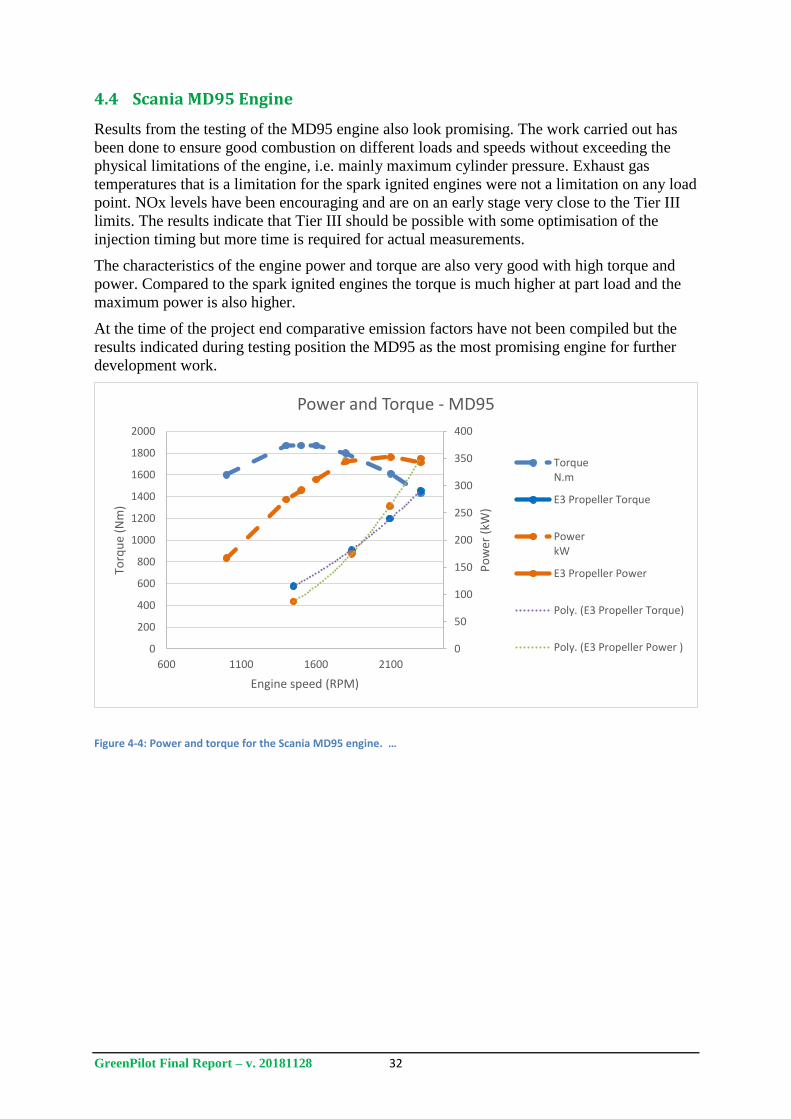
GreenPilot Final Report – v. 20181128 32
4.4 Scania MD95 Engine
Results from the testing of the MD95 engine also look promising. The work carried out has
been done to ensure good combustion on different loads and speeds without exceeding the
physical limitations of the engine, i.e. mainly maximum cylinder pressure. Exhaust gas
temperatures that is a limitation for the spark ignited engines were not a limitation on any load
point. NOx levels have been encouraging and are on an early stage very close to the Tier III
limits. The results indicate that Tier III should be possible with some optimisation of the
injection timing but more time is required for actual measurements.
The characteristics of the engine power and torque are also very good with high torque and
power. Compared to the spark ignited engines the torque is much higher at part load and the
maximum power is also higher.
At the time of the project end comparative emission factors have not been compiled but the
results indicated during testing position the MD95 as the most promising engine for further
development work.
Figure 4-4: Power and torque for the Scania MD95 engine. …
0
50
100
150
200
250
300
350
400
0
200
400
600
800
1000
1200
1400
1600
1800
2000
600 1100 1600 2100
Po
wer
(kW
)
Torq
ue
(Nm
)
Engine speed (RPM)
Power and Torque - MD95
TorqueN.m
E3 Propeller Torque
PowerkW
E3 Propeller Power
Poly. (E3 Propeller Torque)
Poly. (E3 Propeller Power )
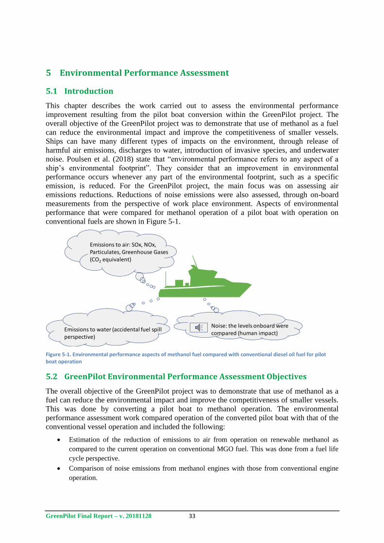
GreenPilot Final Report – v. 20181128 33
5 Environmental Performance Assessment
5.1 Introduction
This chapter describes the work carried out to assess the environmental performance
improvement resulting from the pilot boat conversion within the GreenPilot project. The
overall objective of the GreenPilot project was to demonstrate that use of methanol as a fuel
can reduce the environmental impact and improve the competitiveness of smaller vessels.
Ships can have many different types of impacts on the environment, through release of
harmful air emissions, discharges to water, introduction of invasive species, and underwater
noise. Poulsen et al. (2018) state that “environmental performance refers to any aspect of a
ship’s environmental footprint”. They consider that an improvement in environmental
performance occurs whenever any part of the environmental footprint, such as a specific
emission, is reduced. For the GreenPilot project, the main focus was on assessing air
emissions reductions. Reductions of noise emissions were also assessed, through on-board
measurements from the perspective of work place environment. Aspects of environmental
performance that were compared for methanol operation of a pilot boat with operation on
conventional fuels are shown in Figure 5-1.
Figure 5-1. Environmental performance aspects of methanol fuel compared with conventional diesel oil fuel for pilot boat operation
5.2 GreenPilot Environmental Performance Assessment Objectives
The overall objective of the GreenPilot project was to demonstrate that use of methanol as a
fuel can reduce the environmental impact and improve the competitiveness of smaller vessels.
This was done by converting a pilot boat to methanol operation. The environmental
performance assessment work compared operation of the converted pilot boat with that of the
conventional vessel operation and included the following:
Estimation of the reduction of emissions to air from operation on renewable methanol as
compared to the current operation on conventional MGO fuel. This was done from a fuel life
cycle perspective.
Comparison of noise emissions from methanol engines with those from conventional engine
operation.
Emissions to air: SOx, NOx, Particulates, Greenhouse Gases(CO2 equivalent)
Noise: the levels onboard werecompared (human impact)
Emissions to water (accidental fuel spill perspective)
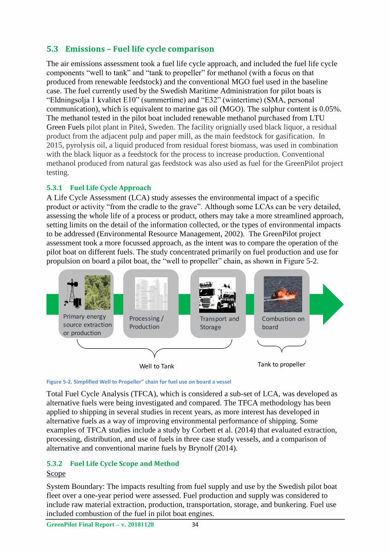
GreenPilot Final Report – v. 20181128 34
5.3 Emissions – Fuel life cycle comparison
The air emissions assessment took a fuel life cycle approach, and included the fuel life cycle
components “well to tank” and “tank to propeller” for methanol (with a focus on that
produced from renewable feedstock) and the conventional MGO fuel used in the baseline
case. The fuel currently used by the Swedish Maritime Administration for pilot boats is
“Eldningsolja 1 kvalitet E10” (summertime) and “E32” (wintertime) (SMA, personal
communication), which is equivalent to marine gas oil (MGO). The sulphur content is 0.05%.
The methanol tested in the pilot boat included renewable methanol purchased from LTU
Green Fuels pilot plant in Piteå, Sweden. The facility orignially used black liquor, a residual
product from the adjacent pulp and paper mill, as the main feedstock for gasification. In
2015, pyrolysis oil, a liquid produced from residual forest biomass, was used in combination
with the black liquor as a feedstock for the process to increase production. Conventional
methanol produced from natural gas feedstock was also used as fuel for the GreenPilot project
testing.
5.3.1 Fuel Life Cycle Approach
A Life Cycle Assessment (LCA) study assesses the environmental impact of a specific
product or activity “from the cradle to the grave”. Although some LCAs can be very detailed,
assessing the whole life of a process or product, others may take a more streamlined approach,
setting limits on the detail of the information collected, or the types of environmental impacts
to be addressed (Environmental Resource Management, 2002). The GreenPilot project
assessment took a more focussed approach, as the intent was to compare the operation of the
pilot boat on different fuels. The study concentrated primarily on fuel production and use for
propulsion on board a pilot boat, the “well to propeller” chain, as shown in Figure 5-2.
Figure 5-2. Simplified Well to Propeller” chain for fuel use on board a vessel
Total Fuel Cycle Analysis (TFCA), which is considered a sub-set of LCA, was developed as
alternative fuels were being investigated and compared. The TFCA methodology has been
applied to shipping in several studies in recent years, as more interest has developed in
alternative fuels as a way of improving environmental performance of shipping. Some
examples of TFCA studies include a study by Corbett et al. (2014) that evaluated extraction,
processing, distribution, and use of fuels in three case study vessels, and a comparison of
alternative and conventional marine fuels by Brynolf (2014).
5.3.2 Fuel Life Cycle Scope and Method
Scope
System Boundary: The impacts resulting from fuel supply and use by the Swedish pilot boat
fleet over a one-year period were assessed. Fuel production and supply was considered to
include raw material extraction, production, transportation, storage, and bunkering. Fuel use
included combustion of the fuel in pilot boat engines.
Primary energysource extractionor production
Well to Tank Tank to propeller
Processing / Production
Transport and Storage
Combustion on board
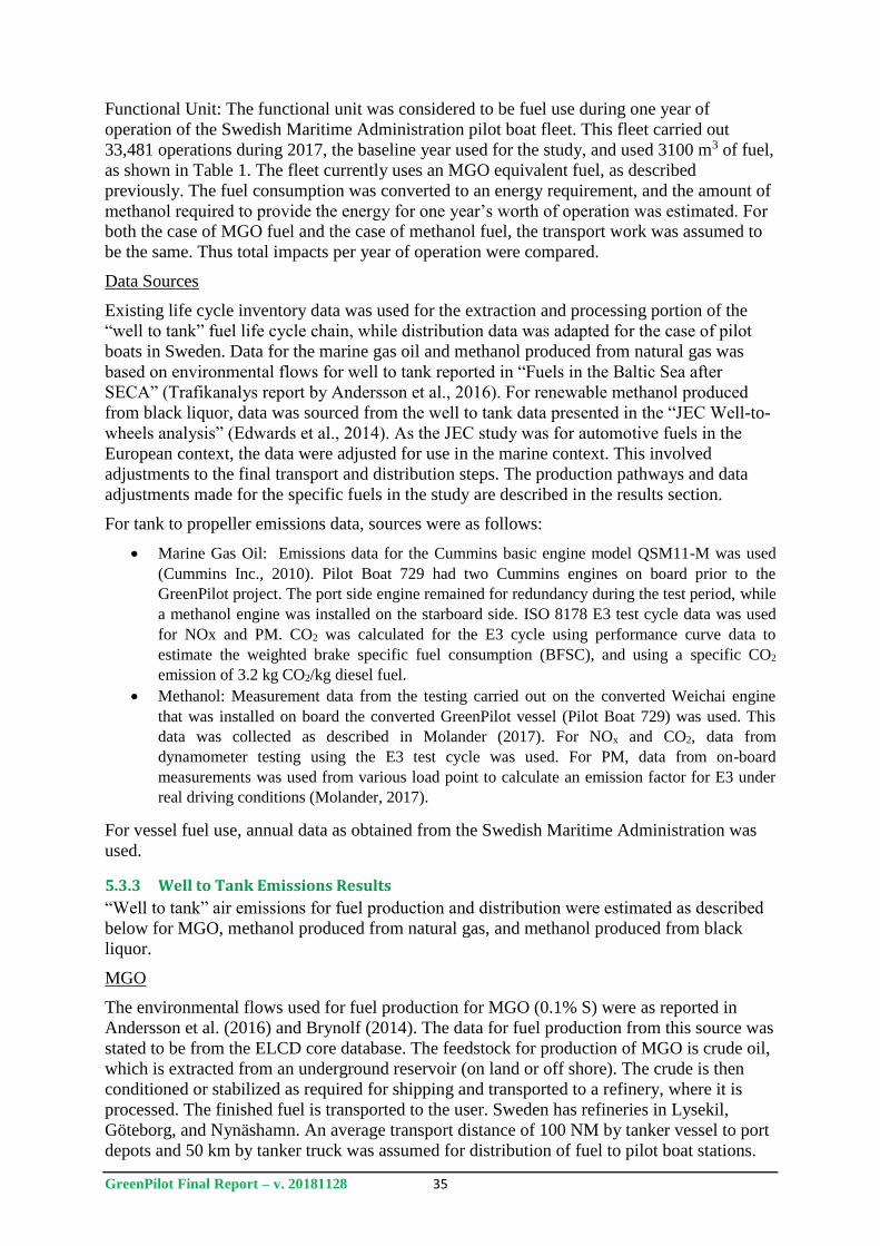
GreenPilot Final Report – v. 20181128 35
Functional Unit: The functional unit was considered to be fuel use during one year of
operation of the Swedish Maritime Administration pilot boat fleet. This fleet carried out
33,481 operations during 2017, the baseline year used for the study, and used 3100 m3 of fuel,
as shown in Table 1. The fleet currently uses an MGO equivalent fuel, as described
previously. The fuel consumption was converted to an energy requirement, and the amount of
methanol required to provide the energy for one year’s worth of operation was estimated. For
both the case of MGO fuel and the case of methanol fuel, the transport work was assumed to
be the same. Thus total impacts per year of operation were compared.
Data Sources
Existing life cycle inventory data was used for the extraction and processing portion of the
“well to tank” fuel life cycle chain, while distribution data was adapted for the case of pilot
boats in Sweden. Data for the marine gas oil and methanol produced from natural gas was
based on environmental flows for well to tank reported in “Fuels in the Baltic Sea after
SECA” (Trafikanalys report by Andersson et al., 2016). For renewable methanol produced
from black liquor, data was sourced from the well to tank data presented in the “JEC Well-to-
wheels analysis” (Edwards et al., 2014). As the JEC study was for automotive fuels in the
European context, the data were adjusted for use in the marine context. This involved
adjustments to the final transport and distribution steps. The production pathways and data
adjustments made for the specific fuels in the study are described in the results section.
For tank to propeller emissions data, sources were as follows:
Marine Gas Oil: Emissions data for the Cummins basic engine model QSM11-M was used
(Cummins Inc., 2010). Pilot Boat 729 had two Cummins engines on board prior to the
GreenPilot project. The port side engine remained for redundancy during the test period, while
a methanol engine was installed on the starboard side. ISO 8178 E3 test cycle data was used
for NOx and PM. CO2 was calculated for the E3 cycle using performance curve data to
estimate the weighted brake specific fuel consumption (BFSC), and using a specific CO2
emission of 3.2 kg CO2/kg diesel fuel.
Methanol: Measurement data from the testing carried out on the converted Weichai engine
that was installed on board the converted GreenPilot vessel (Pilot Boat 729) was used. This
data was collected as described in Molander (2017). For NOx and CO2, data from
dynamometer testing using the E3 test cycle was used. For PM, data from on-board
measurements was used from various load point to calculate an emission factor for E3 under
real driving conditions (Molander, 2017).
For vessel fuel use, annual data as obtained from the Swedish Maritime Administration was
used.
5.3.3 Well to Tank Emissions Results
“Well to tank” air emissions for fuel production and distribution were estimated as described
below for MGO, methanol produced from natural gas, and methanol produced from black
liquor.
MGO
The environmental flows used for fuel production for MGO (0.1% S) were as reported in
Andersson et al. (2016) and Brynolf (2014). The data for fuel production from this source was
stated to be from the ELCD core database. The feedstock for production of MGO is crude oil,
which is extracted from an underground reservoir (on land or off shore). The crude is then
conditioned or stabilized as required for shipping and transported to a refinery, where it is
processed. The finished fuel is transported to the user. Sweden has refineries in Lysekil,
Göteborg, and Nynäshamn. An average transport distance of 100 NM by tanker vessel to port
depots and 50 km by tanker truck was assumed for distribution of fuel to pilot boat stations.
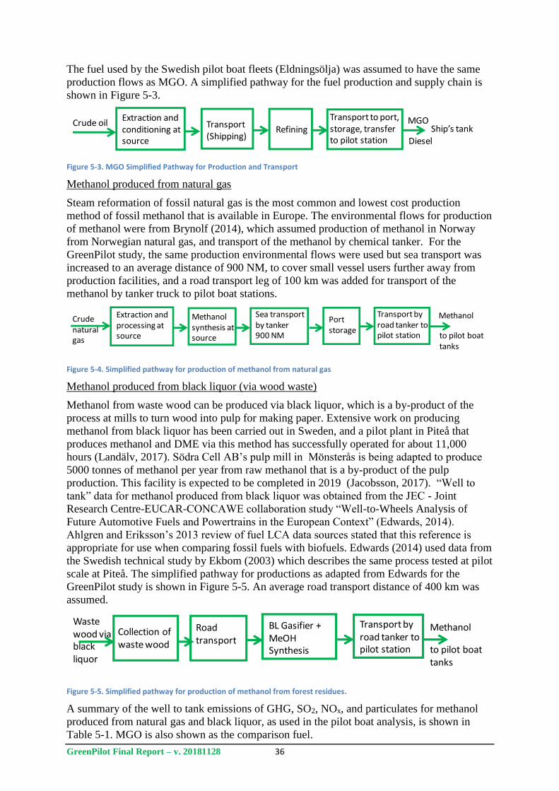
GreenPilot Final Report – v. 20181128 36
The fuel used by the Swedish pilot boat fleets (Eldningsölja) was assumed to have the same
production flows as MGO. A simplified pathway for the fuel production and supply chain is
shown in Figure 5-3.
Figure 5-3. MGO Simplified Pathway for Production and Transport
Methanol produced from natural gas
Steam reformation of fossil natural gas is the most common and lowest cost production
method of fossil methanol that is available in Europe. The environmental flows for production
of methanol were from Brynolf (2014), which assumed production of methanol in Norway
from Norwegian natural gas, and transport of the methanol by chemical tanker. For the
GreenPilot study, the same production environmental flows were used but sea transport was
increased to an average distance of 900 NM, to cover small vessel users further away from
production facilities, and a road transport leg of 100 km was added for transport of the
methanol by tanker truck to pilot boat stations.
Figure 5-4. Simplified pathway for production of methanol from natural gas
Methanol produced from black liquor (via wood waste)
Methanol from waste wood can be produced via black liquor, which is a by-product of the
process at mills to turn wood into pulp for making paper. Extensive work on producing
methanol from black liquor has been carried out in Sweden, and a pilot plant in Piteå that
produces methanol and DME via this method has successfully operated for about 11,000
hours (Landälv, 2017). Södra Cell AB’s pulp mill in Mönsterås is being adapted to produce
5000 tonnes of methanol per year from raw methanol that is a by-product of the pulp
production. This facility is expected to be completed in 2019 (Jacobsson, 2017). “Well to
tank” data for methanol produced from black liquor was obtained from the JEC - Joint
Research Centre-EUCAR-CONCAWE collaboration study “Well-to-Wheels Analysis of
Future Automotive Fuels and Powertrains in the European Context” (Edwards, 2014).
Ahlgren and Eriksson’s 2013 review of fuel LCA data sources stated that this reference is
appropriate for use when comparing fossil fuels with biofuels. Edwards (2014) used data from
the Swedish technical study by Ekbom (2003) which describes the same process tested at pilot
scale at Piteå. The simplified pathway for productions as adapted from Edwards for the
GreenPilot study is shown in Figure 5-5. An average road transport distance of 400 km was
assumed.
Figure 5-5. Simplified pathway for production of methanol from forest residues.
A summary of the well to tank emissions of GHG, SO2, NOx, and particulates for methanol
produced from natural gas and black liquor, as used in the pilot boat analysis, is shown in
Table 5-1. MGO is also shown as the comparison fuel.
Crude oilExtraction and conditioning at source
Transport(Shipping)
Refining
Transport to port, storage, transfer to pilot station
MGO
DieselShip’s tank
Crudenaturalgas
Extraction and processing at source
Methanolsynthesis at source
Sea transport by tanker900 NM
MethanolPort storage
Transport by road tanker to pilot station to pilot boat
tanks
Waste wood via black liquor
Collection ofwaste wood
Methanol
to pilot boattanks
Transport by road tanker to pilot station
BL Gasifier + MeOHSynthesis
Road transport
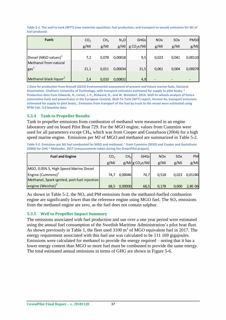
GreenPilot Final Report – v. 20181128 37
Table 5-1. The well to tank (WTT) (raw materials aquisition, fuel production, and transport to vessel) emissions for MJ of fuel produced.
1 Data for production from Brynolf (2014) Environmental assessment of present and future marine fuels. Doctoral Dissertation. Chalmers University of Technology, with transport emissions estimated for supply to pilot boats; 2 Production data from Edwards, R., Larivé, J.-F., Rickeard, D., and W. Weindorf. 2014. Well-to-wheels analysis of future automotive fuels and powertrains in the European Context, Well-To-Tank (WTT) report, Version 4a, transport emissions estimated for supply to pilot boats.. Emissions from transport of the fuel by truck to the vessel were estimated using NTM Calc. 4.0 baseline data.
5.3.4 Tank to Propeller Results
Tank to propeller emissions from combustion of methanol were measured in an engine
laboratory and on board Pilot Boat 729. For the MGO engine, values from Cummins were
used for all parameters except CH4, which was from Cooper and Gustafsson (2004) for a high
speed marine engine. Emissions per MJ of MGO and methanol are summarized in Table 5-2.
Table 5-2. Emissions per MJ fuel combusted for MGO and methanol. 1 from Cummins (2010) and Cooper and Gustafsson (2004) for CH4; 2 Molander, 2017 (measurements taken during the GreenPilot project).
As shown in Table 5-2, the NOx and PM emissions from the methanol-fuelled combustion
engine are significantly lower than the reference engine using MGO fuel. The SOx emissions
from the methanol engine are zero, as the fuel does not contain sulphur.
5.3.5 Well to Propeller Impact Summary
The emissions associated with fuel production and use over a one year period were estimated
using the annual fuel consumption of the Swedish Maritime Administration’s pilot boat fleet.
As shown previously in Table 1, the fleet used 3100 m3 of MGO equivalent fuel in 2017. The
energy requirement associated with this fuel use was calculated to be 111 169 gigajoules.
Emissions were calculated for methanol to provide the energy required – noting that it has a
lower energy content than MGO so more fuel must be combusted to provide the same energy.
The total estimated annual emissions in terms of GHG are shown in Figure 5-6.
Fuels CO2 CH4 N2O GHGs NOx SOx PM10
g/MJ g/MJ g/MJ g CO2e/MJ g/MJ g/MJ g/MJ
Diesel (MGO values)1 7,2 0,078 0,00018 9,5 0,023 0,041 0,00110
Methanol from natural
gas1 21,1 0,011 0,00034 21,5 0,061 0,004 0,00079
Methanol black liquor22,4 0,010 0,00832 4,9 - - -
Fuel and Engine CO2 CH4 GHGs NOx SOx PM
g/MJ g/MJ g CO2e/MJ g/MJ g/MJ g/MJ
MGO, 0.05% S, High Speed Marine Diesel
Engine (Cummins)1 74,7 0,00046 74,7 0,518 0,023 0,01240
Methanol, Spark ignited, port fuel injection
engine (Weichai)268,5 0,00000 68,5 0,178 0,000 2,8E-06
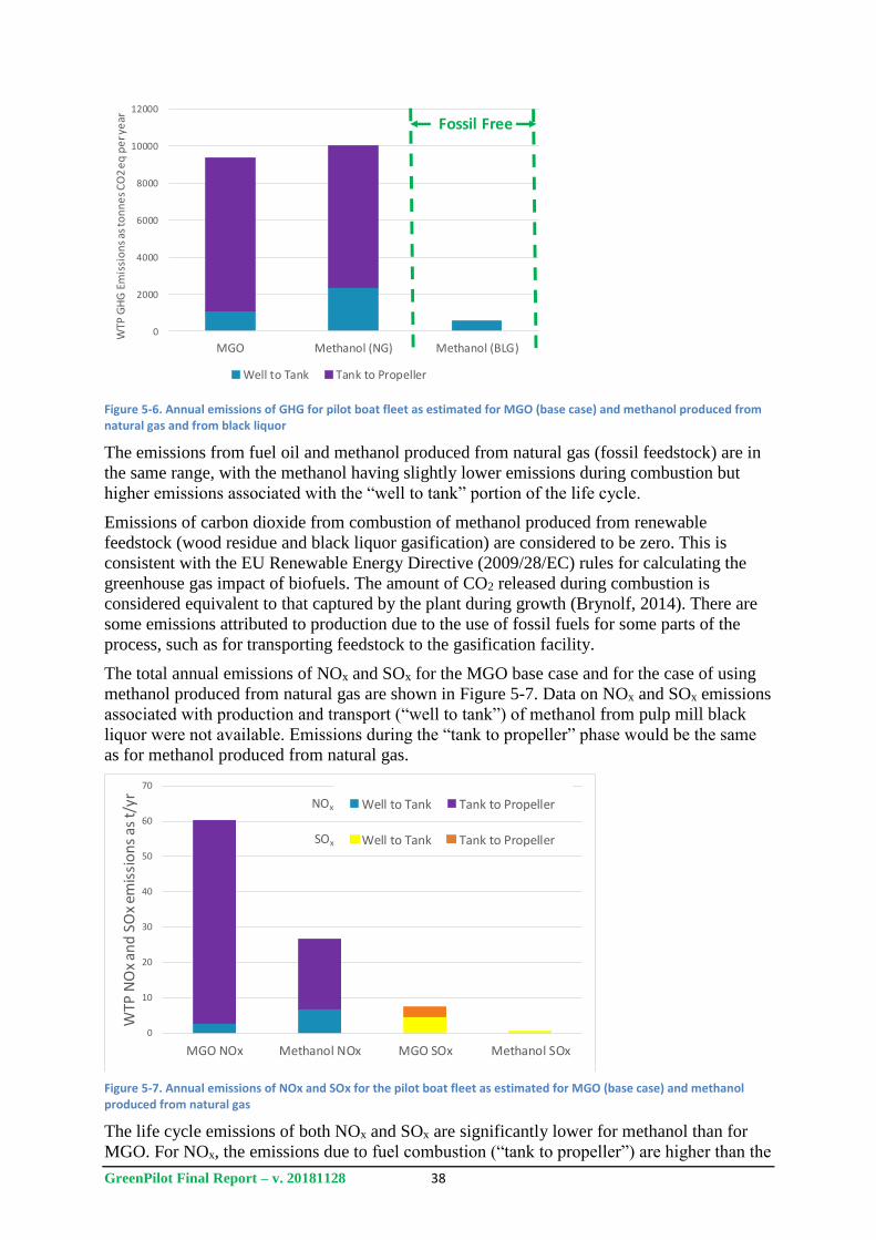
GreenPilot Final Report – v. 20181128 38
Figure 5-6. Annual emissions of GHG for pilot boat fleet as estimated for MGO (base case) and methanol produced from natural gas and from black liquor
The emissions from fuel oil and methanol produced from natural gas (fossil feedstock) are in
the same range, with the methanol having slightly lower emissions during combustion but
higher emissions associated with the “well to tank” portion of the life cycle.
Emissions of carbon dioxide from combustion of methanol produced from renewable
feedstock (wood residue and black liquor gasification) are considered to be zero. This is
consistent with the EU Renewable Energy Directive (2009/28/EC) rules for calculating the
greenhouse gas impact of biofuels. The amount of CO2 released during combustion is
considered equivalent to that captured by the plant during growth (Brynolf, 2014). There are
some emissions attributed to production due to the use of fossil fuels for some parts of the
process, such as for transporting feedstock to the gasification facility.
The total annual emissions of NOx and SOx for the MGO base case and for the case of using
methanol produced from natural gas are shown in Figure 5-7. Data on NOx and SOx emissions
associated with production and transport (“well to tank”) of methanol from pulp mill black
liquor were not available. Emissions during the “tank to propeller” phase would be the same
as for methanol produced from natural gas.
Figure 5-7. Annual emissions of NOx and SOx for the pilot boat fleet as estimated for MGO (base case) and methanol produced from natural gas
The life cycle emissions of both NOx and SOx are significantly lower for methanol than for
MGO. For NOx, the emissions due to fuel combustion (“tank to propeller”) are higher than the
0
2000
4000
6000
8000
10000
12000
MGO Methanol (NG) Methanol (BLG)
WTP
GH
G E
mis
sio
ns
as to
nn
es
CO
2 e
q p
er y
ear
Well to Tank Tank to Propeller
Fossil Free
0
10
20
30
40
50
60
70
MGO NOx Methanol NOx MGO SOx Methanol SOx
WTP
NO
x an
d S
Ox
emis
sio
ns
as t/
yr
Well to Tank Tank to Propeller
0
10
20
30
40
50
60
70
MGO NOx Methanol NOx MGO SOx Methanol SOx
WTP
NO
x an
d S
Ox
emis
sio
ns
as t/
yr
Well to Tank Tank to Propeller
0
10
20
30
40
50
60
70
MGO NOx Methanol NOx MGO SOx Methanol SOx
WTP
NO
x an
d S
Ox
emis
sio
ns
as t/
yr
Well to Tank Tank to PropellerNOx
SOx
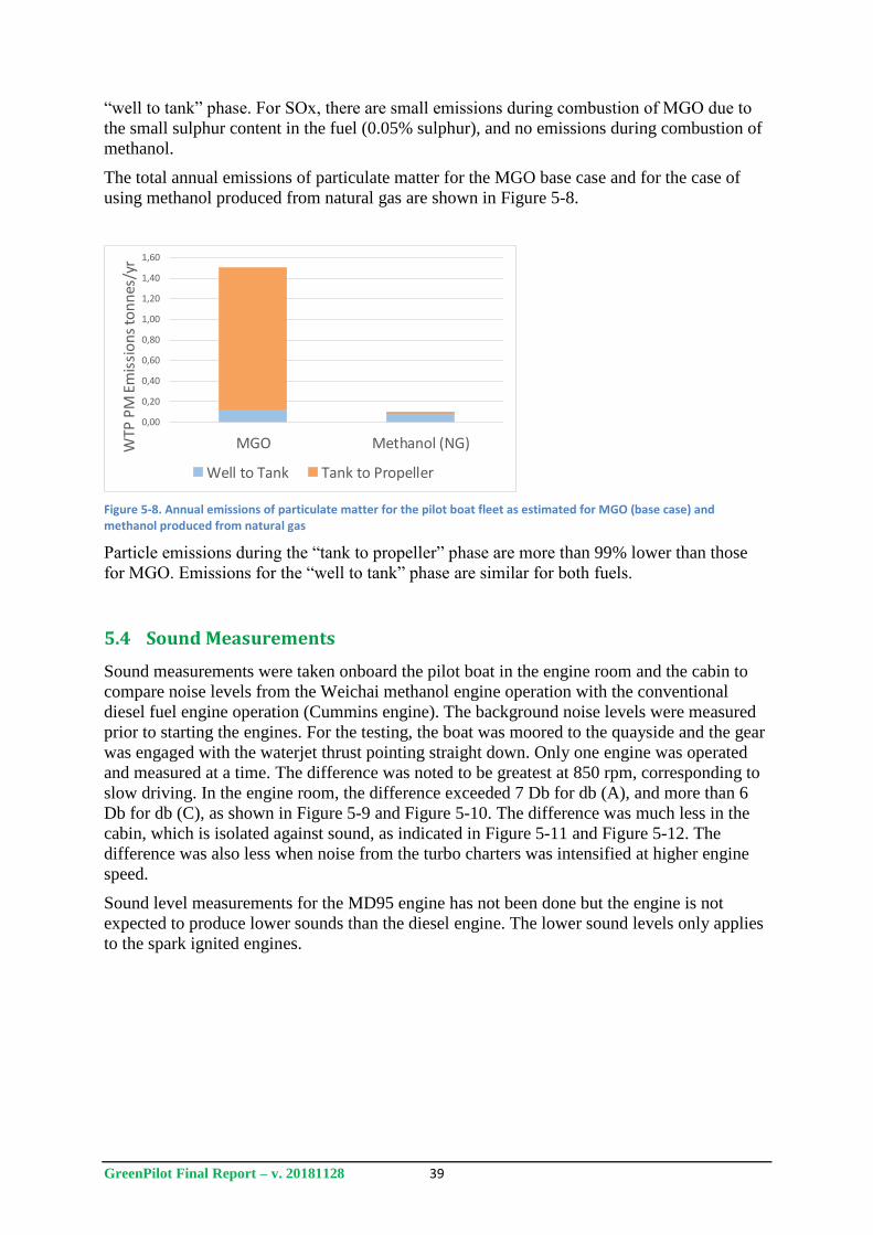
GreenPilot Final Report – v. 20181128 39
“well to tank” phase. For SOx, there are small emissions during combustion of MGO due to
the small sulphur content in the fuel (0.05% sulphur), and no emissions during combustion of
methanol.
The total annual emissions of particulate matter for the MGO base case and for the case of
using methanol produced from natural gas are shown in Figure 5-8.
Figure 5-8. Annual emissions of particulate matter for the pilot boat fleet as estimated for MGO (base case) and methanol produced from natural gas
Particle emissions during the “tank to propeller” phase are more than 99% lower than those
for MGO. Emissions for the “well to tank” phase are similar for both fuels.
5.4 Sound Measurements
Sound measurements were taken onboard the pilot boat in the engine room and the cabin to
compare noise levels from the Weichai methanol engine operation with the conventional
diesel fuel engine operation (Cummins engine). The background noise levels were measured
prior to starting the engines. For the testing, the boat was moored to the quayside and the gear
was engaged with the waterjet thrust pointing straight down. Only one engine was operated
and measured at a time. The difference was noted to be greatest at 850 rpm, corresponding to
slow driving. In the engine room, the difference exceeded 7 Db for db (A), and more than 6
Db for db (C), as shown in Figure 5-9 and Figure 5-10. The difference was much less in the
cabin, which is isolated against sound, as indicated in Figure 5-11 and Figure 5-12. The
difference was also less when noise from the turbo charters was intensified at higher engine
speed.
Sound level measurements for the MD95 engine has not been done but the engine is not
expected to produce lower sounds than the diesel engine. The lower sound levels only applies
to the spark ignited engines.
0,00
0,20
0,40
0,60
0,80
1,00
1,20
1,40
1,60
MGO Methanol (NG)WTP
PM
Em
issi
on
s to
nn
es/y
r
Well to Tank Tank to Propeller
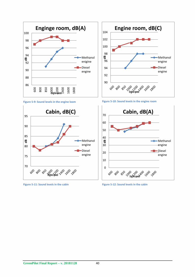
GreenPilot Final Report – v. 20181128 40
Figure 5-9: Sound levels in the engine loom
Figure 5-10: Sound levels in the engine room
Figure 5-11: Sound levels in the cabin
Figure 5-12: Sound levels in the cabin
86
88
90
92
94
96
98
1006
00
80
0
85
0
10
00
12
00
14
00
16
00
18
00
dB
Enginge room, dB(A)
Methanolenigine
Dieselengine
90
92
94
96
98
100
102
104
dB
Engine room, dB(C)
Methanolengine
Dieselengine
70
75
80
85
90
95
dB
Cabin, dB(C)
Methanolengine
Dieselengine
0
10
20
30
40
50
60
70
dB
Cabin, dB(A)
Methanolengine
Dieselengine
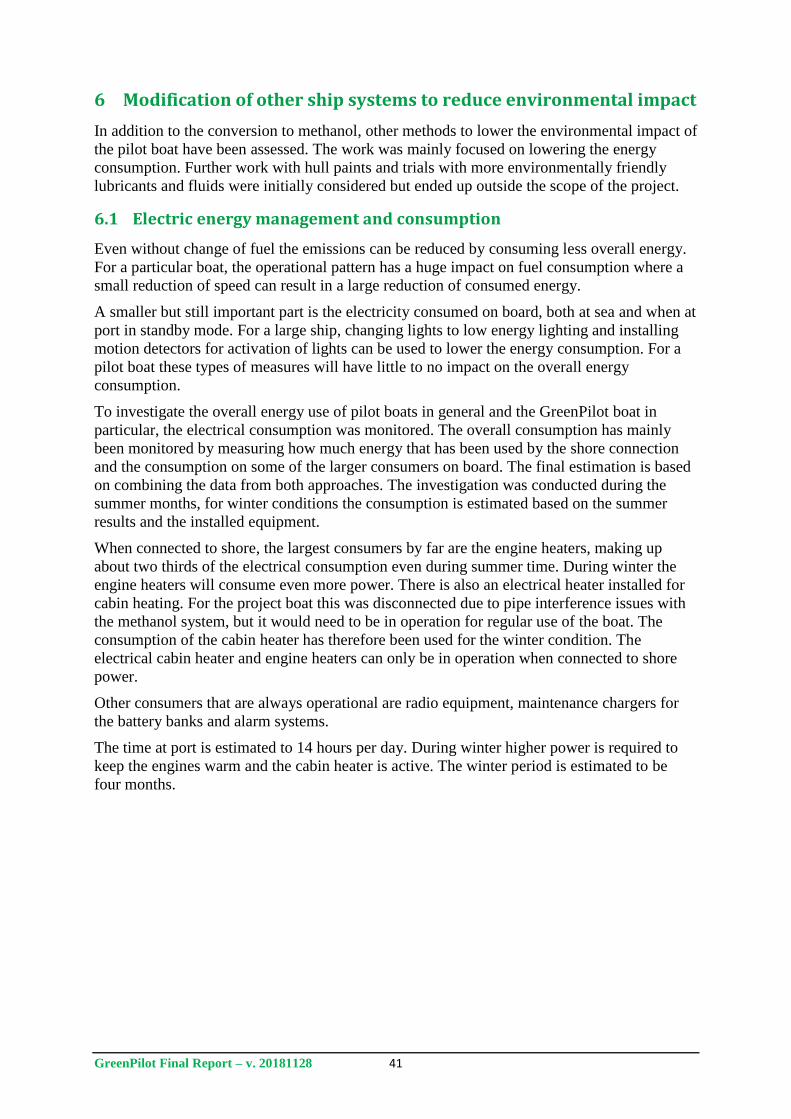
GreenPilot Final Report – v. 20181128 41
6 Modification of other ship systems to reduce environmental impact
In addition to the conversion to methanol, other methods to lower the environmental impact of
the pilot boat have been assessed. The work was mainly focused on lowering the energy
consumption. Further work with hull paints and trials with more environmentally friendly
lubricants and fluids were initially considered but ended up outside the scope of the project.
6.1 Electric energy management and consumption
Even without change of fuel the emissions can be reduced by consuming less overall energy.
For a particular boat, the operational pattern has a huge impact on fuel consumption where a
small reduction of speed can result in a large reduction of consumed energy.
A smaller but still important part is the electricity consumed on board, both at sea and when at
port in standby mode. For a large ship, changing lights to low energy lighting and installing
motion detectors for activation of lights can be used to lower the energy consumption. For a
pilot boat these types of measures will have little to no impact on the overall energy
consumption.
To investigate the overall energy use of pilot boats in general and the GreenPilot boat in
particular, the electrical consumption was monitored. The overall consumption has mainly
been monitored by measuring how much energy that has been used by the shore connection
and the consumption on some of the larger consumers on board. The final estimation is based
on combining the data from both approaches. The investigation was conducted during the
summer months, for winter conditions the consumption is estimated based on the summer
results and the installed equipment.
When connected to shore, the largest consumers by far are the engine heaters, making up
about two thirds of the electrical consumption even during summer time. During winter the
engine heaters will consume even more power. There is also an electrical heater installed for
cabin heating. For the project boat this was disconnected due to pipe interference issues with
the methanol system, but it would need to be in operation for regular use of the boat. The
consumption of the cabin heater has therefore been used for the winter condition. The
electrical cabin heater and engine heaters can only be in operation when connected to shore
power.
Other consumers that are always operational are radio equipment, maintenance chargers for
the battery banks and alarm systems.
The time at port is estimated to 14 hours per day. During winter higher power is required to
keep the engines warm and the cabin heater is active. The winter period is estimated to be
four months.
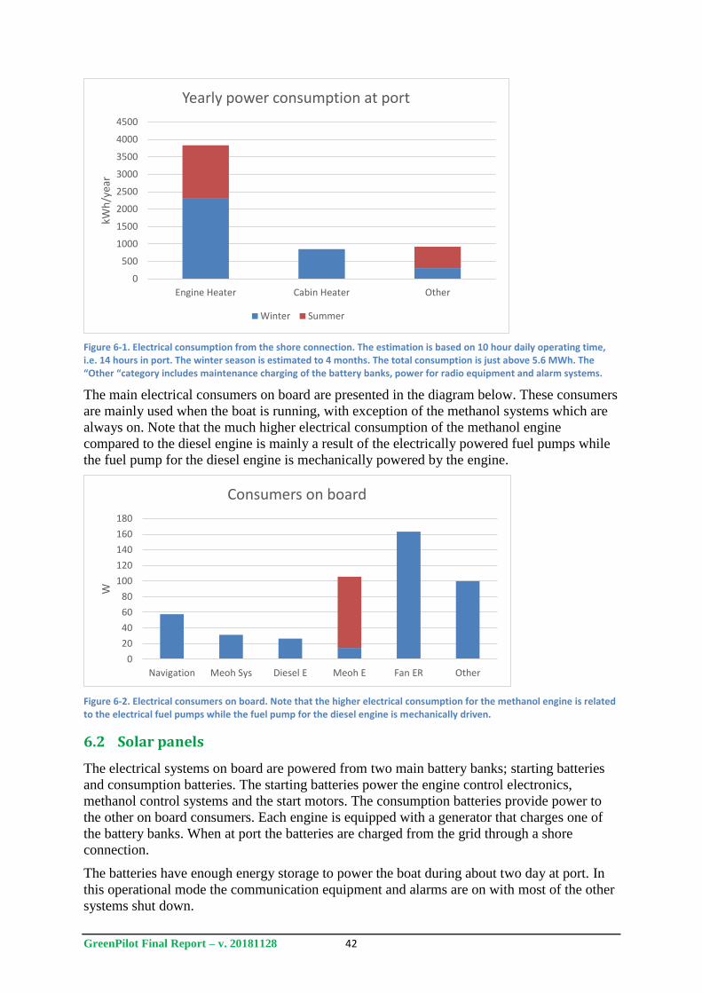
GreenPilot Final Report – v. 20181128 42
Figure 6-1. Electrical consumption from the shore connection. The estimation is based on 10 hour daily operating time, i.e. 14 hours in port. The winter season is estimated to 4 months. The total consumption is just above 5.6 MWh. The “Other “category includes maintenance charging of the battery banks, power for radio equipment and alarm systems.
The main electrical consumers on board are presented in the diagram below. These consumers
are mainly used when the boat is running, with exception of the methanol systems which are
always on. Note that the much higher electrical consumption of the methanol engine
compared to the diesel engine is mainly a result of the electrically powered fuel pumps while
the fuel pump for the diesel engine is mechanically powered by the engine.
Figure 6-2. Electrical consumers on board. Note that the higher electrical consumption for the methanol engine is related to the electrical fuel pumps while the fuel pump for the diesel engine is mechanically driven.
6.2 Solar panels
The electrical systems on board are powered from two main battery banks; starting batteries
and consumption batteries. The starting batteries power the engine control electronics,
methanol control systems and the start motors. The consumption batteries provide power to
the other on board consumers. Each engine is equipped with a generator that charges one of
the battery banks. When at port the batteries are charged from the grid through a shore
connection.
The batteries have enough energy storage to power the boat during about two day at port. In
this operational mode the communication equipment and alarms are on with most of the other
systems shut down.
0
500
1000
1500
2000
2500
3000
3500
4000
4500
Engine Heater Cabin Heater Other
kWh
/yea
rYearly power consumption at port
Winter Summer
0
20
40
60
80
100
120
140
160
180
Navigation Meoh Sys Diesel E Meoh E Fan ER Other
W
Consumers on board
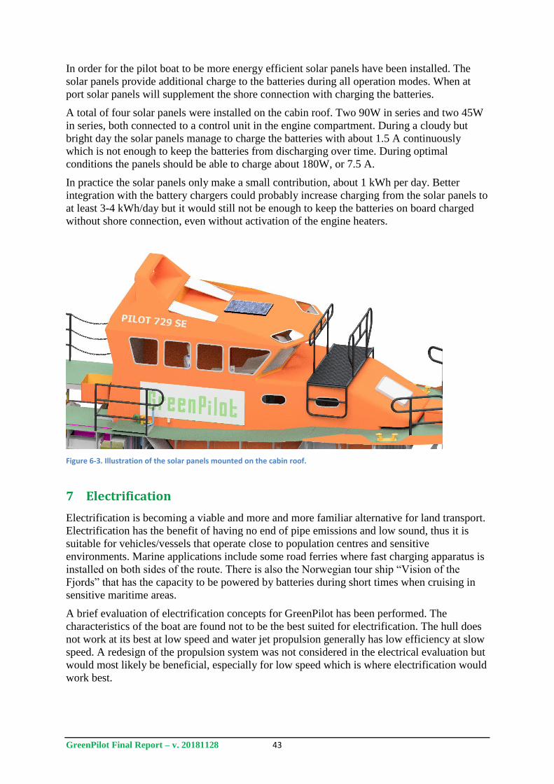
GreenPilot Final Report – v. 20181128 43
In order for the pilot boat to be more energy efficient solar panels have been installed. The
solar panels provide additional charge to the batteries during all operation modes. When at
port solar panels will supplement the shore connection with charging the batteries.
A total of four solar panels were installed on the cabin roof. Two 90W in series and two 45W
in series, both connected to a control unit in the engine compartment. During a cloudy but
bright day the solar panels manage to charge the batteries with about 1.5 A continuously
which is not enough to keep the batteries from discharging over time. During optimal
conditions the panels should be able to charge about 180W, or 7.5 A.
In practice the solar panels only make a small contribution, about 1 kWh per day. Better
integration with the battery chargers could probably increase charging from the solar panels to
at least 3-4 kWh/day but it would still not be enough to keep the batteries on board charged
without shore connection, even without activation of the engine heaters.
Figure 6-3. Illustration of the solar panels mounted on the cabin roof.
7 Electrification
Electrification is becoming a viable and more and more familiar alternative for land transport.
Electrification has the benefit of having no end of pipe emissions and low sound, thus it is
suitable for vehicles/vessels that operate close to population centres and sensitive
environments. Marine applications include some road ferries where fast charging apparatus is
installed on both sides of the route. There is also the Norwegian tour ship “Vision of the
Fjords” that has the capacity to be powered by batteries during short times when cruising in
sensitive maritime areas.
A brief evaluation of electrification concepts for GreenPilot has been performed. The
characteristics of the boat are found not to be the best suited for electrification. The hull does
not work at its best at low speed and water jet propulsion generally has low efficiency at slow
speed. A redesign of the propulsion system was not considered in the electrical evaluation but
would most likely be beneficial, especially for low speed which is where electrification would
work best.
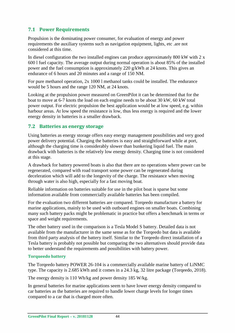
GreenPilot Final Report – v. 20181128 44
7.1 Power Requirements
Propulsion is the dominating power consumer, for evaluation of energy and power
requirements the auxiliary systems such as navigation equipment, lights, etc .are not
considered at this time.
In diesel configuration the two installed engines can produce approximately 800 kW with 2 x
600 l fuel capacity. The average output during normal operation is about 85% of the installed
power and the fuel consumption is approximately 220 g/kWh at 24 knots. This gives an
endurance of 6 hours and 20 minutes and a range of 150 NM.
For pure methanol operation, 2x 1000 l methanol tanks could be installed. The endurance
would be 5 hours and the range 120 NM, at 24 knots.
Looking at the propulsion power measured on GreenPilot it can be determined that for the
boat to move at 6-7 knots the load on each engine needs to be about 30 kW, 60 kW total
power output. For electric propulsion the best application would be at low speed, e.g. within
harbour areas. At low speed the resistance is low, thus less energy is required and the lower
energy density in batteries is a smaller drawback.
7.2 Batteries as energy storage
Using batteries as energy storage offers easy energy management possibilities and very good
power delivery potential. Charging the batteries is easy and straightforward while at port,
although the charging time is considerably slower than bunkering liquid fuel. The main
drawback with batteries is the relatively low energy density. Charging time is not considered
at this stage.
A drawback for battery powered boats is also that there are no operations where power can be
regenerated, compared with road transport some power can be regenerated during
deceleration which will add to the longevity of the charge. The resistance when moving
through water is also high, especially for a fast moving boat.
Reliable information on batteries suitable for use in the pilot boat is sparse but some
information available from commercially available batteries has been compiled.
For the evaluation two different batteries are compared. Torqeedo manufacture a battery for
marine applications, mainly to be used with outboard engines on smaller boats. Combining
many such battery packs might be problematic in practice but offers a benchmark in terms or
space and weight requirements.
The other battery used in the comparison is a Tesla Model S battery. Detailed data is not
available from the manufacturer in the same sense as for the Torqeedo but data is available
from third party analysis of the battery itself. Similar to the Torqeedo direct installation of a
Tesla battery is probably not possible but comparing the two alternatives should provide data
to better understand the requirements and possibilities with battery power.
Torqueedo battery
The Torqeedo battery POWER 26-104 is a commercially available marine battery of LiNMC
type. The capacity is 2.685 kWh and it comes in a 24.3 kg, 32 litre package (Torqeedo, 2018).
The energy density is 110 Wh/kg and power density 185 W/kg.
In general batteries for marine applications seem to have lower energy density compared to
car batteries as the batteries are required to handle lower charge levels for longer times
compared to a car that is charged more often.
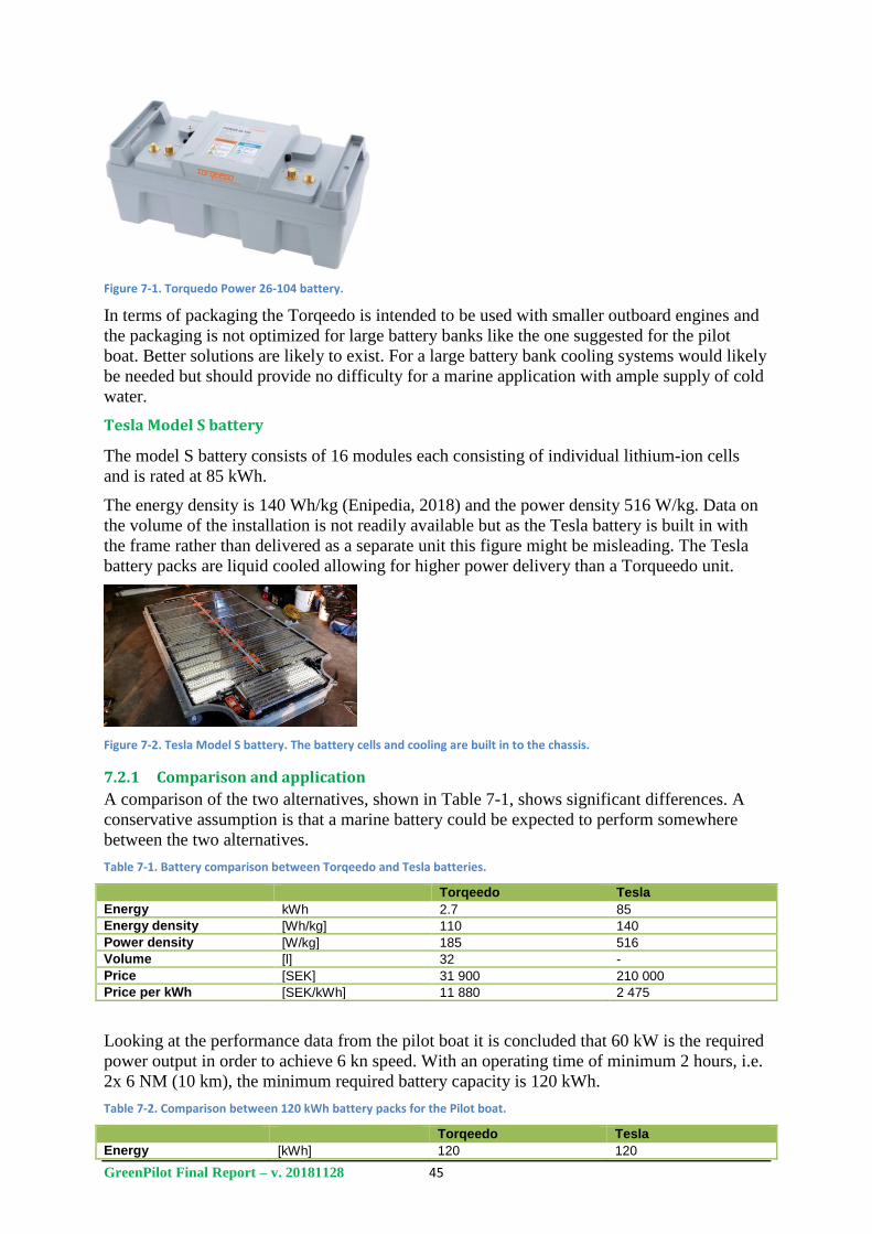
GreenPilot Final Report – v. 20181128 45
Figure 7-1. Torquedo Power 26-104 battery.
In terms of packaging the Torqeedo is intended to be used with smaller outboard engines and
the packaging is not optimized for large battery banks like the one suggested for the pilot
boat. Better solutions are likely to exist. For a large battery bank cooling systems would likely
be needed but should provide no difficulty for a marine application with ample supply of cold
water.
Tesla Model S battery
The model S battery consists of 16 modules each consisting of individual lithium-ion cells
and is rated at 85 kWh.
The energy density is 140 Wh/kg (Enipedia, 2018) and the power density 516 W/kg. Data on
the volume of the installation is not readily available but as the Tesla battery is built in with
the frame rather than delivered as a separate unit this figure might be misleading. The Tesla
battery packs are liquid cooled allowing for higher power delivery than a Torqueedo unit.
Figure 7-2. Tesla Model S battery. The battery cells and cooling are built in to the chassis.
7.2.1 Comparison and application
A comparison of the two alternatives, shown in Table 7-1, shows significant differences. A
conservative assumption is that a marine battery could be expected to perform somewhere
between the two alternatives.
Table 7-1. Battery comparison between Torqeedo and Tesla batteries.
Torqeedo Tesla
Energy kWh 2.7 85
Energy density [Wh/kg] 110 140
Power density [W/kg] 185 516
Volume [l] 32 -
Price [SEK] 31 900 210 000
Price per kWh [SEK/kWh] 11 880 2 475
Looking at the performance data from the pilot boat it is concluded that 60 kW is the required
power output in order to achieve 6 kn speed. With an operating time of minimum 2 hours, i.e.
2x 6 NM (10 km), the minimum required battery capacity is 120 kWh.
Table 7-2. Comparison between 120 kWh battery packs for the Pilot boat.
Torqeedo Tesla
Energy [kWh] 120 120
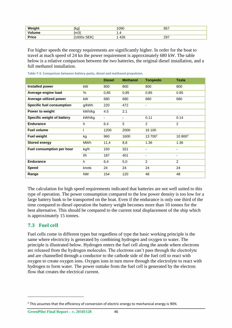
GreenPilot Final Report – v. 20181128 46
Weight [kg] 1090 857
Volume [m3] 1.4
Price [1000x SEK] 1 426 297
For higher speeds the energy requirements are significantly higher. In order for the boat to
travel at mach speed of 24 kn the power requirement is approximately 680 kW. The table
below is a relative comparison between the two batteries, the original diesel installation, and a
full methanol installation.
Table 7-3. Comparison between battery packs, diesel and methanol propulsion.
Diesel Methanol Torqeedo Tesla
Installed power kW 800 800 800 800
Average engine load % 0,85 0,85 0,85 0.85
Average utilized power kW 680 680 680 680
Specific fuel consumption g/kWh 220 472 -
Power to weight kWh/kg 4.5 2.1
Specific weight of battery kWh/kg - - 0.11 0.14
Endurance h 6.4 5 2 2
Fuel volume l 1200 2000 16 100
Fuel weight kg 960 1600 13 7002 10 8003
Stored energy MWh 11,4 8,8 1.36 1.36
Fuel consumption per hour kg/h 150 321 - -
l/h 187 401 - -
Endurance h 6,4 5,0 2 2
Speed knots 24 24 24 24
Range NM 154 120 48 48
The calculation for high speed requirements indicated that batteries are not well suited to this
type of operation. The power consumption compared to the low power density is too low for a
large battery bank to be transported on the boat. Even if the endurance is only one third of the
time compared to diesel operation the battery weight becomes more than 10 tonnes for the
best alternative. This should be compared to the current total displacement of the ship which
is approximately 15 tonnes.
7.3 Fuel cell
Fuel cells come in different types but regardless of type the basic working principle is the
same where electricity is generated by combining hydrogen and oxygen to water. The
principle is illustrated below. Hydrogen enters the fuel cell along the anode where electrons
are released from the hydrogen molecules. The electrons can’t pass through the electrolyte
and are channelled through a conductor to the cathode side of the fuel cell to react with
oxygen to create oxygen ions. Oxygen ions in turn move through the electrolyte to react with
hydrogen to form water. The power outtake from the fuel cell is generated by the electron
flow that creates the electrical current.
2 This assumes that the efficiency of conversion of electric energy to mechanical energy is 90%
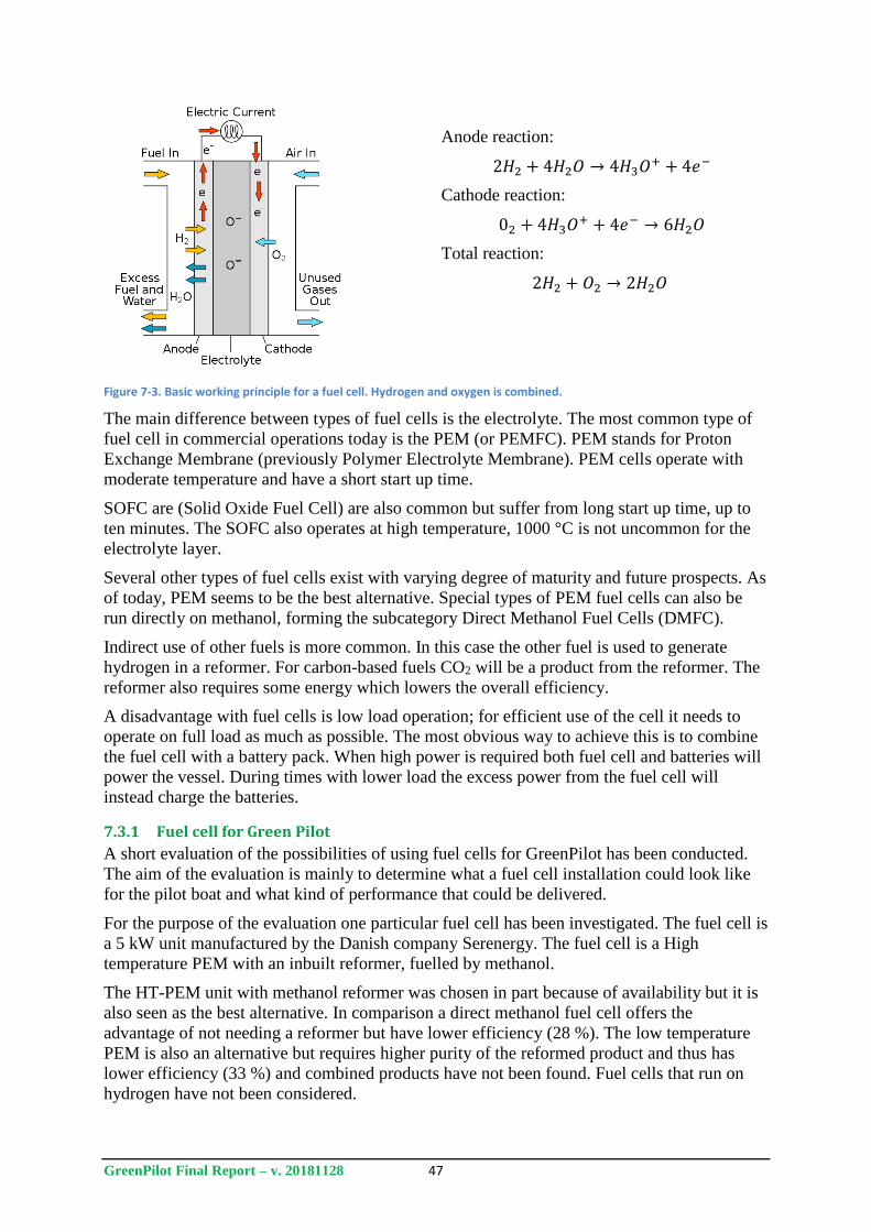
GreenPilot Final Report – v. 20181128 47
Anode reaction:
2𝐻2 + 4𝐻2𝑂 → 4𝐻3𝑂+ + 4𝑒−
Cathode reaction:
02 + 4𝐻3𝑂+ + 4𝑒− → 6𝐻2𝑂
Total reaction:
2𝐻2 + 𝑂2 → 2𝐻2𝑂
Figure 7-3. Basic working principle for a fuel cell. Hydrogen and oxygen is combined.
The main difference between types of fuel cells is the electrolyte. The most common type of
fuel cell in commercial operations today is the PEM (or PEMFC). PEM stands for Proton
Exchange Membrane (previously Polymer Electrolyte Membrane). PEM cells operate with
moderate temperature and have a short start up time.
SOFC are (Solid Oxide Fuel Cell) are also common but suffer from long start up time, up to
ten minutes. The SOFC also operates at high temperature, 1000 °C is not uncommon for the
electrolyte layer.
Several other types of fuel cells exist with varying degree of maturity and future prospects. As
of today, PEM seems to be the best alternative. Special types of PEM fuel cells can also be
run directly on methanol, forming the subcategory Direct Methanol Fuel Cells (DMFC).
Indirect use of other fuels is more common. In this case the other fuel is used to generate
hydrogen in a reformer. For carbon-based fuels CO2 will be a product from the reformer. The
reformer also requires some energy which lowers the overall efficiency.
A disadvantage with fuel cells is low load operation; for efficient use of the cell it needs to
operate on full load as much as possible. The most obvious way to achieve this is to combine
the fuel cell with a battery pack. When high power is required both fuel cell and batteries will
power the vessel. During times with lower load the excess power from the fuel cell will
instead charge the batteries.
7.3.1 Fuel cell for Green Pilot
A short evaluation of the possibilities of using fuel cells for GreenPilot has been conducted.
The aim of the evaluation is mainly to determine what a fuel cell installation could look like
for the pilot boat and what kind of performance that could be delivered.
For the purpose of the evaluation one particular fuel cell has been investigated. The fuel cell is
a 5 kW unit manufactured by the Danish company Serenergy. The fuel cell is a High
temperature PEM with an inbuilt reformer, fuelled by methanol.
The HT-PEM unit with methanol reformer was chosen in part because of availability but it is
also seen as the best alternative. In comparison a direct methanol fuel cell offers the
advantage of not needing a reformer but have lower efficiency (28 %). The low temperature
PEM is also an alternative but requires higher purity of the reformed product and thus has
lower efficiency (33 %) and combined products have not been found. Fuel cells that run on
hydrogen have not been considered.
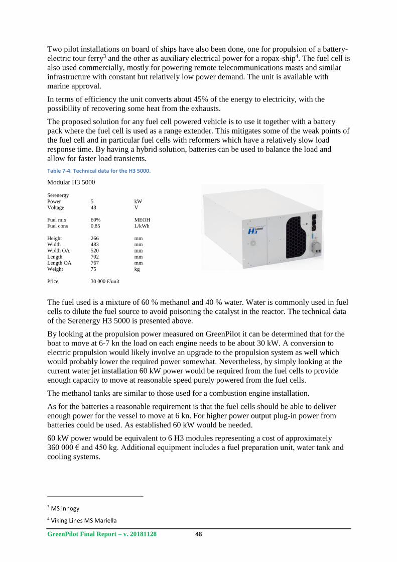
GreenPilot Final Report – v. 20181128 48
Two pilot installations on board of ships have also been done, one for propulsion of a battery-
electric tour ferry3 and the other as auxiliary electrical power for a ropax-ship4. The fuel cell is
also used commercially, mostly for powering remote telecommunications masts and similar
infrastructure with constant but relatively low power demand. The unit is available with
marine approval.
In terms of efficiency the unit converts about 45% of the energy to electricity, with the
possibility of recovering some heat from the exhausts.
The proposed solution for any fuel cell powered vehicle is to use it together with a battery
pack where the fuel cell is used as a range extender. This mitigates some of the weak points of
the fuel cell and in particular fuel cells with reformers which have a relatively slow load
response time. By having a hybrid solution, batteries can be used to balance the load and
allow for faster load transients.
Table 7-4. Technical data for the H3 5000.
Modular H3 5000
Serenergy
Power 5 kW Voltage 48 V
Fuel mix 60% MEOH Fuel cons 0,85 L/kWh
Height 266 mm Width 483 mm
Width OA 520 mm
Length 702 mm Length OA 767 mm
Weight 75 kg
Price 30 000 €/unit
The fuel used is a mixture of 60 % methanol and 40 % water. Water is commonly used in fuel
cells to dilute the fuel source to avoid poisoning the catalyst in the reactor. The technical data
of the Serenergy H3 5000 is presented above.
By looking at the propulsion power measured on GreenPilot it can be determined that for the
boat to move at 6-7 kn the load on each engine needs to be about 30 kW. A conversion to
electric propulsion would likely involve an upgrade to the propulsion system as well which
would probably lower the required power somewhat. Nevertheless, by simply looking at the
current water jet installation 60 kW power would be required from the fuel cells to provide
enough capacity to move at reasonable speed purely powered from the fuel cells.
The methanol tanks are similar to those used for a combustion engine installation.
As for the batteries a reasonable requirement is that the fuel cells should be able to deliver
enough power for the vessel to move at 6 kn. For higher power output plug-in power from
batteries could be used. As established 60 kW would be needed.
60 kW power would be equivalent to 6 H3 modules representing a cost of approximately
360 000 € and 450 kg. Additional equipment includes a fuel preparation unit, water tank and
cooling systems.
3 MS innogy
4 Viking Lines MS Mariella
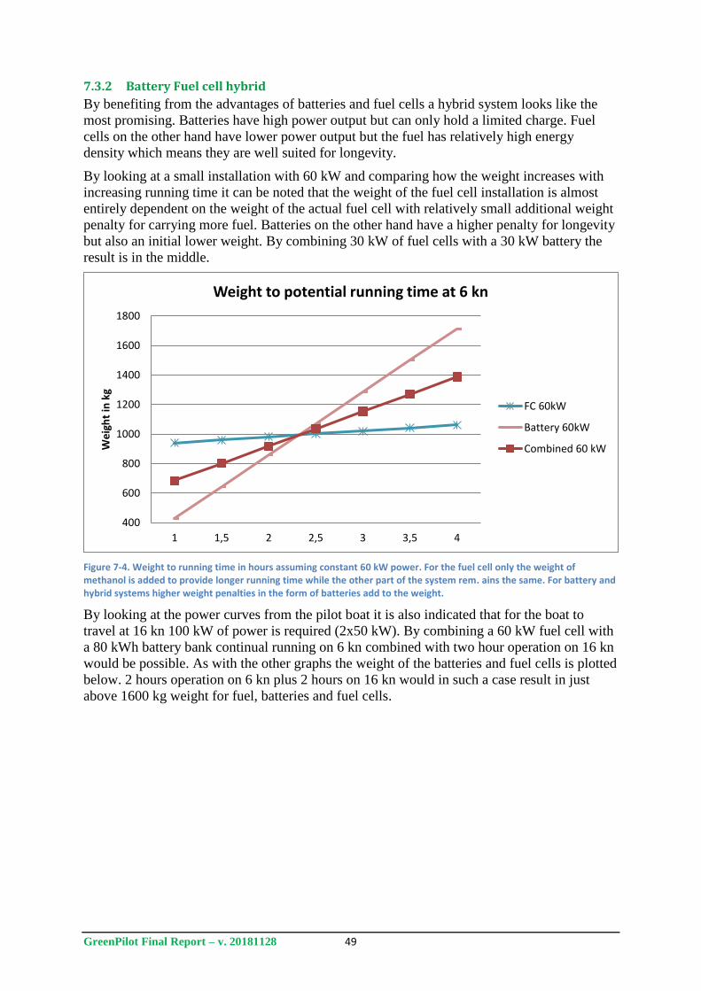
GreenPilot Final Report – v. 20181128 49
7.3.2 Battery Fuel cell hybrid
By benefiting from the advantages of batteries and fuel cells a hybrid system looks like the
most promising. Batteries have high power output but can only hold a limited charge. Fuel
cells on the other hand have lower power output but the fuel has relatively high energy
density which means they are well suited for longevity.
By looking at a small installation with 60 kW and comparing how the weight increases with
increasing running time it can be noted that the weight of the fuel cell installation is almost
entirely dependent on the weight of the actual fuel cell with relatively small additional weight
penalty for carrying more fuel. Batteries on the other hand have a higher penalty for longevity
but also an initial lower weight. By combining 30 kW of fuel cells with a 30 kW battery the
result is in the middle.
Figure 7-4. Weight to running time in hours assuming constant 60 kW power. For the fuel cell only the weight of methanol is added to provide longer running time while the other part of the system rem. ains the same. For battery and hybrid systems higher weight penalties in the form of batteries add to the weight.
By looking at the power curves from the pilot boat it is also indicated that for the boat to
travel at 16 kn 100 kW of power is required (2x50 kW). By combining a 60 kW fuel cell with
a 80 kWh battery bank continual running on 6 kn combined with two hour operation on 16 kn
would be possible. As with the other graphs the weight of the batteries and fuel cells is plotted
below. 2 hours operation on 6 kn plus 2 hours on 16 kn would in such a case result in just
above 1600 kg weight for fuel, batteries and fuel cells.
400
600
800
1000
1200
1400
1600
1800
1 1,5 2 2,5 3 3,5 4
We
igh
t in
kg
Weight to potential running time at 6 kn
FC 60kW
Battery 60kW
Combined 60 kW
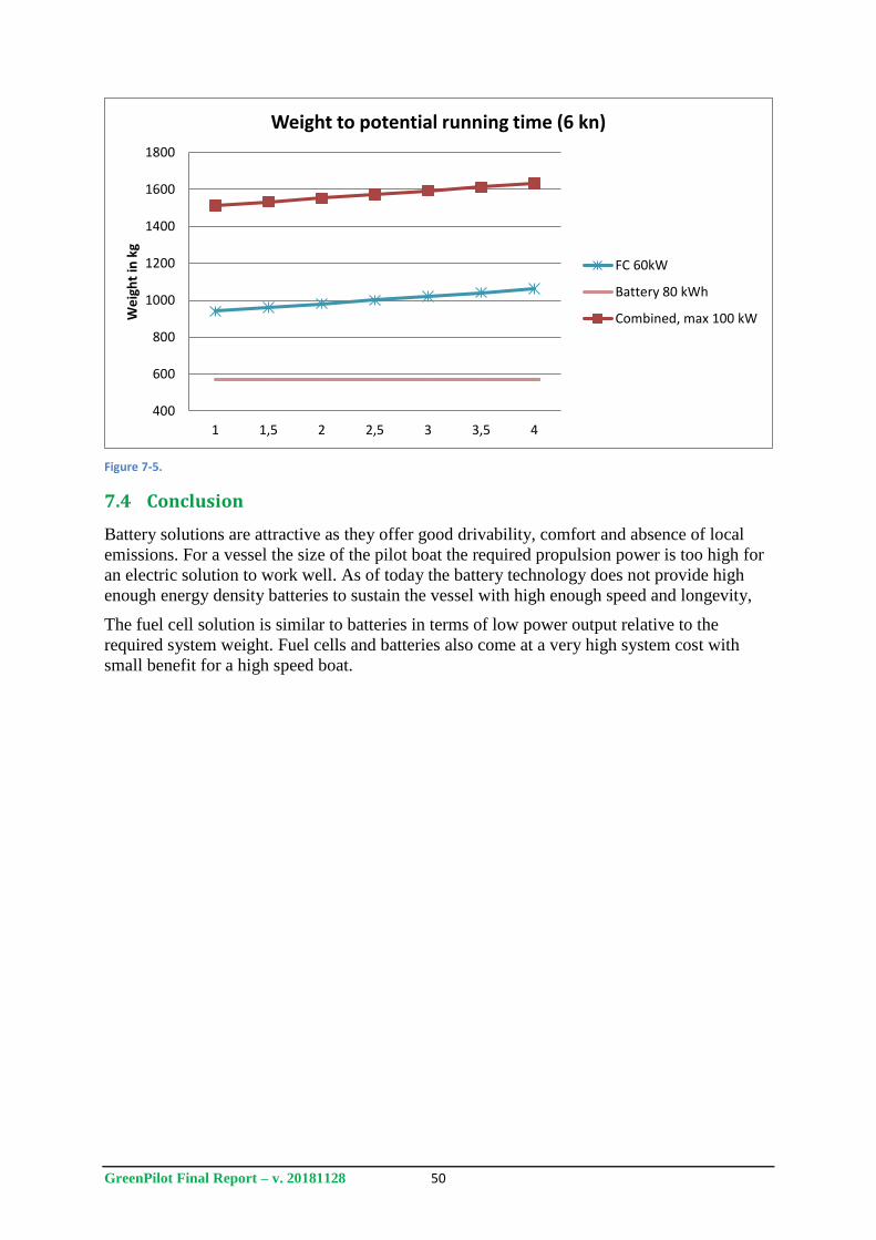
GreenPilot Final Report – v. 20181128 50
Figure 7-5.
7.4 Conclusion
Battery solutions are attractive as they offer good drivability, comfort and absence of local
emissions. For a vessel the size of the pilot boat the required propulsion power is too high for
an electric solution to work well. As of today the battery technology does not provide high
enough energy density batteries to sustain the vessel with high enough speed and longevity,
The fuel cell solution is similar to batteries in terms of low power output relative to the
required system weight. Fuel cells and batteries also come at a very high system cost with
small benefit for a high speed boat.
400
600
800
1000
1200
1400
1600
1800
1 1,5 2 2,5 3 3,5 4
We
igh
t in
kg
Weight to potential running time (6 kn)
FC 60kW
Battery 80 kWh
Combined, max 100 kW

GreenPilot Final Report – v. 20181128 51
8 Project Communication and Dissemination Activities
The work carried out in GreenPilot has been widely communicated both in Sweden and
internationally. The marine methanol community has followed the development of the project,
resulting in numerous invitations for international presentations and a high level of
international visitors at the end-of-project seminar. Engines from the project have been on
display at two national events and at two international shipping exhibitions under the Swedish
flag in the Swedish national pavilion. Shipping exhibitions were identified as an effective way
to demonstrate the close proximity of the project results to market and to reach new
international contacts. Exposure has predominantly been given in the context of marine fuels
and propulsion, but the project has also been communicated in the general context of
sustainable transport and green technology.
The GreenPilot consortia recognized at an early stage in the project’s planning phase the
potential, however uncertain, for GreenPilot to lead to yet another marine methanol success
story following the work carried out on Stena Germanica in the larger engine segment.
Communicating GreenPilot and its high innovation level benefited from the hands-on nature
of the project, the technical novelty of the conversion, the high profile financiers and the
potential for high commercial value in the smaller engine segment. Dissemination activities
have hence targeted a wide variety of audiences focusing on, but not limited to, the maritime
industry. “External” stakeholders include policy makers, biofuel producers, the methanol
value chain as well as the general public. A full outline of the project as well as the final
report is accessible via the homepage www.greenpilot.se. The webpage has generated
contacts with journalists and people curious to learn more about the technical details of the
project. It was decided that the homepage will be maintained beyond the final date of the
project as the GreenPilot consortia will continue building on the knowledge achieved in
GreenPilot and carry it into other projects.
In summary the dissemination of GreenPilot has contributed to Sweden’s cutting edge profile
in areas of green and sustainable propulsion in general and methanol propulsion in particular.
A selection of communication activities throughout the project, shown in Table 9-1, shows the
spread and reach of GreenPilot.
Table 9-1: Selection of GreenPilot Communication Activities
What When Event/Media Where
Project Kick-off June 2016 Seminar Gothenburg, Sweden
Mid-Project Update June 2017 Seminar Gothenburg, Sweden
End of Project Seminar May 2018 Seminar Gothenburg, Sweden
International Shipping Exhibition June 2017 Nor-Shipping Lilleström, Norway
National Exhibition on Climate November 2017 Klimatforum Stockholm, Sweden
International Shipping Exhibition September 2018 SMM Hamburg, Germany
Donsö Shipping Meeting September 2017 DSM Donsö Island, Sweden
Articles
June 2016 Sjöfartstidningen Sweden
August 2016 Sjövägen Sweden
June 2017 Skärgårdsredaren Sweden
July 2017 Svenskt Båtägande Sweden
July 2017 Svenska Dagbladet Sweden

GreenPilot Final Report – v. 20181128 52
October 2017
Proffessional Mariner Magazine USA
October 2018 Marine Proffessionals IMarEST
UK
Pressrelease SMM September 2018 My News Desk:
Fire News USA
Broadly Boats News - Firetrench UK
Industry Europe UK
All About Shipping UK
Bunker Index UK
Panel Debate April 2017 Ekotransport Conference Stockholm, Sweden
Presentations June 2016 Almedalen Visby, Sweden
September 2016 India's Leap Into Methanol Economy
New Dehli, India
October 2016 Making Marine Applications Greener
Reykjavik, Iceland
January 2017 TRANSPORTFORUM Linköping, Sweden
June 2017 Marine Fuel Beyond LNG - Methanol as an Alternative?
Elsfleth, Germany
June 2017 IMPCA Methanol Conference
Hamburg, Germany
October 2017 Meeting with India's Minister of Transport
New Delhi, India
March 2018 MAN & Methanol Institute Workshop
Copenhagen, Denmark
June 2018 Swedish Transport Administration's Research and Innovation Day - Shipping 2018
Stockholm, Sweden
October 2018 Maritime Cluster Norddeutschland
Hamburg, Germany
Visits to the Pilot Boat April 2017 "Billion Miles" representative from Singapore
Gothenburg, Sweden
April 2017 Swedish CIMAC Members
Gothenburg, Sweden
February 2018 Delegation from Port of Hamburg
Gothenburg, Sweden
GreenPilot Final Report – v. 20181128 53
9 Discussion and Conclusions
Pilot Boat 729 was successfully converted to methanol operation and tested at sea with good
overall results. On-board emissions testing showed very low particulate emissions and
significant NOx reductions. For the two engines tested on board the vessel, diesel-like
performance was shown, with engine efficiencies ranging from 37-40%. Another positive
experience was the lower sound from the engines. The spark ignited methanol engines have a
significantly lower sound level which improves the working environment onboard. The sound
is also at higher frequency which makes sound insulation easier.
9.1 Lessons learned / recommendations for further improvements
During the testing no issues with material incompatibility were noted and no issues with the
engines arose. The Weichai engine has been partly dissembled after use to inspect the
cylinders and valves for wear. No excessive wear was noted, but the testing time was also
limited and further long term evaluation of methanol use is necessary.
For the test vessel using one diesel engine and one methanol engine did not adversely affect
the manoeuvrability, to a large extent due to the use of water jets. The main issue on board
during testing was that there was some difficulty when engaging and disengaging the gear.
This is in part an engine optimization problem but also a result of using the existing hardware
that was installed for diesel engines. Equipment for gasoline engines generally engages the
gear in a smoother manner to prevent the engine from stalling.
9.1.1 Tank metering
The fuel tanks were equipped with floating point resistance gauges. These have not worked as
well as expected, exhibiting slow response and low measuring resolution. This has been a
problem in particular during bunkering where there has been uncertainty about the available
space in the tanks.
For future projects a different type of tank measurement is advised. A secondary high-high
meter is also advised with possibility to connect the alarm to bunker shutoff functionality.
As the bunker tanks are located above the on board fuel tanks and no air can enter the hose or
bunker manifold, the system works as a siphon during bunkering; shutdown of the transfer
pump does not stop methanol transfer. An automatic shutdown therefore needs some
additional equipment to be effective. There are a number of possible solutions:
1. Remote operated shutoff valves on each bunker line
2. Remote operated shutoff line on the bunker station (with boat-shore communication interface)
3. Vacuum valve on bunker line
Each proposal has pros and cons. On board shutoff valves have some advantages such as fast
response and additional safety during service of the bunker connection. The solution is on the
other hand expensive and the serviceability of the actual valve may be limited due to lack of
surrounding space.
Equipment located on the actual bunker station is likely preferred but for a portable solution it
would complicate the system and would not work that well for the current setup. For a
permanent or semi-permanent bunker station a remote shutoff valve would likely be the best
solution.
Remote shutoff for the bunkering would also allow for faster bunkering while maintaining
safe operation.
GreenPilot Final Report – v. 20181128 54
9.1.2 PV valve spray protection
The tank ventilation exits high on port side of the cabin. A high location was determined to be
the best solution in order to allow for easy dilution of possible fuel vapours exhausted through
the ventilation. The high location was also preferred in order to somewhat protect the valve
from the sea in heavy weather.
The location itself could be retained for the tank ventilation outlet but it should be equipped
with a spray hood to direct any methanol overflow from the tanks. The hood would also work
as extra weather protection.
In case of overflow the hood would stop fuel from being dispersed to the sides and instead
direct a more controlled flow downwards. An important task is also to collect small airborne
droplets that would be easier to inhale for the crew.
Spray protection on the ventilation outlet is advised regardless of whether tank inertion is
used or not.
9.1.3 Tank inertion
The fuel tanks in the pilot boat are inerted with nitrogen. Inertion is a requirement in the draft
IGF technical provisions for methyl/ethyl alcohol and in the classification rules for low
flashpoint fuels. For transportation of methanol this is not a requirement of the IGC code but
has become common practice for many of the large tankers; both to improve safety and to
keep the methanol pure. For road transportation and storage facilities inertion is not used.
For a small boat inertion is not practical due mainly to space requirements but also auxiliary
system requirements. These obstacles are easier to overcome on large ships where the large
quantities of fuel will also motivate the additional safety. For smaller ships and vessels there
should be some crossover point where inertion no longer provides additional safety but
instead overcomplicates the system design with the risk of introducing new hazards.
GreenPilot is designed with a nitrogen inertion system that works but it can be questioned if it
should be required. Conventional atmospheric fuel tanks should provide enough safety.
In the case of using atmospheric fuel tanks the P/V valve on the tank ventilation should be
exchanged with a flame arrestor to prevent any flame from propagating down the ventilation
pipe.
For the bunker manifold the dry disconnect coupling would prevent any flame to propagate
through the bunker pipes as the connection is always closed when disconnected. During
connection and disconnection the two parts outer casing will engage before the connection
opens, thus any build-up of static electricity would discharge before any methanol could be
ignited.
9.2 Environmental Performance Improvements
A comparison of estimated annual emissions of the pilot boat fleet for MGO and methanol for
GHGs, NOx, SOx, and particulate matter showed that significant emissions reductions could
be achieved with the adoption of methanol fuel. For greenhouse gas emissions, reductions in
the range of 90% could be achieved with the use of renewable methanol produced from pulp
mill black liquor. For methanol produced from natural gas, a fossil feedstock, greenhouse gas
emissions are similar to those from MGO fuel.
NOx emissions were much lower from combustion of methanol during the “tank to propeller”
phase than they were from combustion of MGO. There are no SOx emissions from methanol
combustion, and very small emissions during the “well to tank” portion of the fuel life cycle.
GreenPilot Final Report – v. 20181128 55
Particle emissions were significantly reduced with methanol combustion as compared to
MGO.
9.3 Potential small vessel market for methanol fuel
The GreenPilot project successfully demonstrated that a small vessel can be converted to run
on methanol fuel, with significantly reduced emissions as compared to conventional
petroleum fuel. Vessels operating in areas with stricter emissions requirements, or those with
operators that have a strong incentive to reduce their emissions due to corporate or
government strategic goals, are likely first adopters of methanol fuel.
9.3.1 Inland waterway vessels
Inland waterway vessels are an example where stricter emissions regulations are coming into
force soon. The EU Stage V emission limits, applicable to non-road mobile machinery
including inland waterway vessel engines, comes in to force on 1 January 2019 for engines
with net power less than 300 kW, and on 1 January 2020 for those with net power of 300 kW
or higher. These regulations require significant reductions of hydrocarbons (HC), NOx, and
Particulate Matter (PM). The standards will be applicable to both newbuilds and any
conversions done after the applicable date.
To fulfil the new Stage V emission limits most diesel engines will have to use after-treatment
systems such as particle filters, oxidation catalysts and selective catalytic reduction (SCR)
system with urea (e,g, AdBlue, a liquid solution of urea). The cost of the after-treatment
systems needed for a diesel engine will be in the same range as the base engine itself. The
systems are voluminous and might be difficult to fit in an engine room and will generate
running costs for consumables and maintenance.
A methanol-fuelled engine can fulfil the toughest requirements for PM and NOx with a simple
and inexpensive passive 3-way catalyst, and thus could be a very cost (and space) competitive
alternative. There are about 200 – 300 new inland waterway vessels delivered within EU
annually. These will be good candidates for methanol operation.
India has allocated money to improve the utilization of inland waterways, and there is
incentive to use a fuel that can be produced nationally and that has low emissions. The
government has proposed using methanol as a fuel for inland waterway vessels (Economic
Times, 2018). A program for renewing the fleet with 500 vessels has been decided (ref).
China has a similar interest in shifting cargo from road to inland waterways and to operate the
inland waterway vessel on clean burning fuel.
9.3.2 Renewable methanol for meeting CO2 reduction targets
Some governments and corporations are already setting targets for reducing their CO2
emissions ahead of any regulations. The Swedish government, for example, is currently
investigating alternatives for converting all state vessels to fossil-free operations. All of the
fossil-free fuels currently cost more than conventional options, but methanol has the potential
to be competitive within this segment. This could be particularly true where there is local
production of fossil free methanol. The following operations are considered to be premium
candidates for use of renewable methanol:
Operations under direct or indirect government control (national or municipal levels)
o Pilot boat operation
o Road ferries
o Ice breakers
o Coat guards
o Waterborne public transportation
o Harbour crafts (tugs, fire department)

GreenPilot Final Report – v. 20181128 56
o Search and rescue operation
Operations where the customers are environmentally conscious
o Passenger and cruise operation, particularly in environmental sensitive areas
Pleasure craft
GreenPilot Final Report – v. 20181128 57
10 References
Anderson, K., Brynolf, S., and M. Izzo. 2016. Fuels in the Baltic Sea after SECA.
Trafikanalys PM 2016:12. Stockholm: Trafikanalys Available:
http://www.trafa.se/globalassets/pm/pm-2016_12-fuels-in-the-baltic-sea-after-seca.pdf
Bohl, T., Smallbone, A., Tian, G., and A.P. Roskilly. 2018. Particulate number and NOx
trade-off comparisons between HVO and mineral diesel in HD applications. Fuel 215 (2018)
90-101.
Borg, U. 2018. Personal communication.
Brynolf, S., Fridell, E. and K. Andersson. 2014. Environmental assessment of marine fuels:
liquefied natural gas, liquefied biogas, methanol and bio-methanol. Journal of Cleaner
Production, 74, 86-95.
Cooper, D. and T. Gustafsson, 2004. “Methodology for calculating emissions from ships: 1,
Update of emission factors”, Report series SMED and SMED&SLU Nr 4 2004
(http://www.smed.se/).
Corbett, J.J., Thomson, H., and J.J. Winebrake. 2014. Natural Gas for Waterborne Freight
Transport: A Life Cycle Emissions Assessment with Case Studies. Report prepared for US
Department of Transportation, Maritime Administration.
Cummins Inc. 2010. Marine Performance Curves. Curve Number M-20093.
Edwards, R., Larivé, J.-F., Rickeard, D., and W. Weindorf. 2014. Well-to-wheels analysis of
future automotive fuels and powertrains in the European Context, Well-To-Tank (WTT)
report, Version 4a, April 2014. JRC Technical report of study carried out jointly by JRC,
EUCAR, and CONCAWE. Luxembourg: Publications Office of the European Union.
Enipedia Tesla Model S Battery http://enipedia.tudelft.nl/wiki/Tesla_Model_S_Battery
[Accessed 23 April 2018]
Environmental Resources Management. 2002. Streamlined Life Cycle Assessment of Two
Marks & Spencer plc Apparel Products. Draft Final Report. Report prepared for Marks &
Spencer plc. Oxford, U.K. Available:
http://www2.marksandspencer.com/thecompany/ourcommitmenttosociety/environment/pdfs/
Final_LCA_report.pdf
Evegren, F. 2017. proFLASH: Methanol fire detection and extinguishment. SP Rapport
2017:22. Borås: RISE Research Institutes of Sweden.
Hsieh, C.-W. C. and C. Felby. 2017. Biofuels for the marine shipping sector. IEA Bioenergy
Report.
IMO. 2018. UN body adopts climate change strategy for shipping. Available from:
http://www.imo.org/en/MediaCentre/PressBriefings/Pages/06GHGinitialstrategy.aspx
[Accessed: 16 April 2018].
Jacobsson, M. 2017. Södra mångmiljonsatsar på biodrivmedel. Skog Supply. Available:
https://www.skog-supply.se/article/view/552636/sodra_mangmiljonsatsar_pa_biodrivmedel
Lack, D.A., Thuesen, J., Elliot, R., Stuer-Lauridsen, F., Overgaard, S.B., and D. Kristensen.
2015. Investigation of appropriate control measures (abatement technologies) to reduce balck
carbon emissions from international shipping. London: IMO.
GreenPilot Final Report – v. 20181128 58
Landälv, I. 2017. Methanol as a renewable fuel – a knowledge synthesis. Report No 2015:08,
f3 The Swedish Knowledge Centre for Renewable Transportation Fuels, Sweden. Available
at: www.f3centre.se.
Myhre, G., Shindell, D., Bréon, F.-M., Collins, W., Fuglestvedt, J., Huang, J., Koch, D.,
Lamarque, J.-F., Lee, D., Mendoza, B., Nakajima, T., Robock, A., Stephens, G., Takemura, T.
& Zhang, H. (2013). Anthropogenic and Natural Radiative Forcing. In: Climate Change 2013:
The Physical Science Basis. Contribution of Working Group I to the Fifth Assessment Report
of the Intergovernmental Panel on Climate Change [Stocker, T.F., Qin, D., Plattner, G.-K.,
Tignor, M., Allen, S.K., Boschung, J., Nauels, A., Xia, Y., Bex, V. & Midgley, P.M. (eds.)].
Cambridge University Press, Cambridge, United Kingdom and New York, NY, US
Molander, P. 2017. Field Test 2 – Environmental Performance Methanol Engine. GreenPilot
Report 7.2.
Poulsen, R.T., Hermann, R.R., and C.K. Smink. 2018. Do eco-rating schemes improve the
environmental performance of ships? Marine Policy 87, pp. 94-103.
Rapport från riksdagen 2017/18:RFR13 Fossilfria drivmedel för att minska transportsektorns
klimatpåverkan
Rashed, M.M, Kalam, M.A., Masjuki, H.H., Rashedul, H.K., Ashraful, A.M., Schancita,I. and
A.M. Ruhul. 2015. Stability of biodiesel, its improvement and the effect of antioxidant treated
blends on engine performance and emission. RSC Adv., 2015, 5, 36240.
Regeringskansliet. 2018. Regeringen ger uppdrag att analysera fossilfrihet för statligt ägda
fartyg. Published 20180223. Available:
http://www.regeringen.se/pressmeddelanden/2018/02/regeringen-ger-uppdrag-att-analysera-
fossilfrihet-for-statligt-agda-fartyg/. Accessed 20180228.
Sjöfartsverket. 2017. Redovisning av miljöledningsarbetet 2016 Sjöfartsverket.
Sjöfartsverket. 2017b. Hållbarhetsredovisning 2016 för Sjöfartsverket. Ed. Ulrika Borg.
Norrköping: Sjöfartsverket. Available from: www.sjofartsverket.se [Accessed 20180203].
Sjöfartsverket. 2018a. Hållbarhetsredovisning 2017 för Sjöfartsverket. Ed. Ulrika Borg.
Norrköping: Sjöfartsverket. Available from: www.sjofartsverket.se [Accessed 20180423].
Sjöfartsverket. 2016. Hållbarhetsredovisning 2015 för Sjöfartsverket. Ed. Ulrika Borg.
Norrköping: Sjöfartsverket. Available from: www.sjofartsverket.se [Accessed 20180203].
Sucden, 2015.World Ethanol Market. Available: http://www.sucden.com/statistics/10_world-
ethanol-market [accessed 20150820].
The Economic Times. 2017. Government to promote methanol as alternative fuel. Available:
https://economictimes.indiatimes.com/industry/energy/oil-gas/government-to-promote-
methanol-as-alternative-fuel/articleshow/62140269.cms [Accessed 2 September 2018]
Torqeedo. https://torqeedo.se/products/product/power-26-104/ [Accessed 23 April 2018]
Tunér, M., Aakko-Saksa, P., and P. Molander. 2018. Engine Technology, Research, and
Development for Methanol in Internal Combustion Engines. SUMMETH Project Deliverable
D3.1.

GreenPilot Final Report – v. 20181128 I
Appendix I – Methanol Safety Sheet
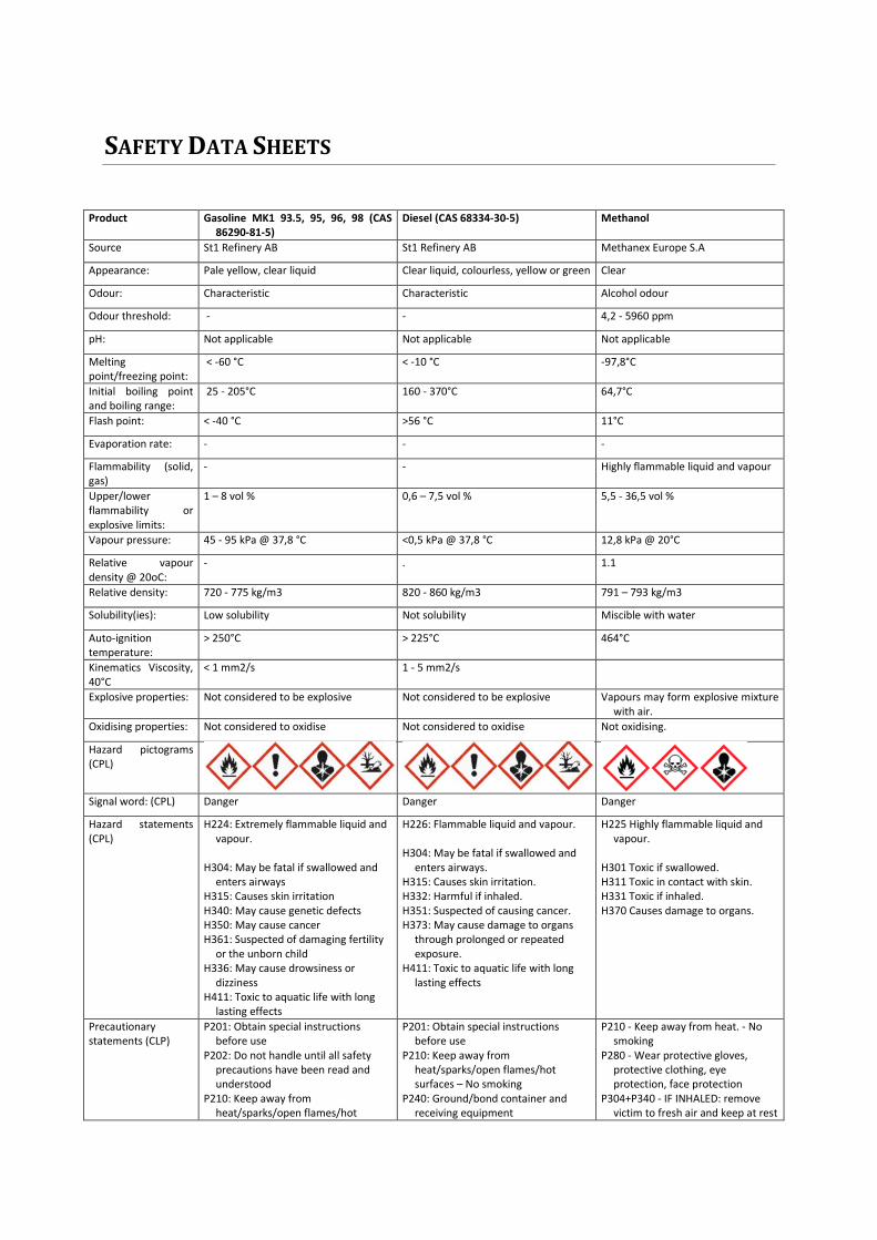
SAFETY DATA SHEETS
Product Gasoline MK1 93.5, 95, 96, 98 (CAS 86290-81-5)
Diesel (CAS 68334-30-5) Methanol
Source St1 Refinery AB St1 Refinery AB Methanex Europe S.A
Appearance: Pale yellow, clear liquid Clear liquid, colourless, yellow or green Clear
Odour: Characteristic Characteristic Alcohol odour
Odour threshold: - - 4,2 - 5960 ppm
pH: Not applicable Not applicable Not applicable
Melting point/freezing point:
< -60 °C < -10 °C -97,8°C
Initial boiling point and boiling range:
25 - 205°C 160 - 370°C 64,7°C
Flash point: < -40 °C >56 °C 11°C
Evaporation rate: - - -
Flammability (solid, gas)
- - Highly flammable liquid and vapour
Upper/lower flammability or explosive limits:
1 – 8 vol % 0,6 – 7,5 vol % 5,5 - 36,5 vol %
Vapour pressure: 45 - 95 kPa @ 37,8 °C <0,5 kPa @ 37,8 °C 12,8 kPa @ 20°C
Relative vapour density @ 20oC:
- . 1.1
Relative density: 720 - 775 kg/m3 820 - 860 kg/m3 791 – 793 kg/m3
Solubility(ies): Low solubility Not solubility Miscible with water
Auto-ignition temperature:
> 250°C > 225°C 464°C
Kinematics Viscosity, 40°C
< 1 mm2/s 1 - 5 mm2/s
Explosive properties: Not considered to be explosive Not considered to be explosive Vapours may form explosive mixture with air.
Oxidising properties: Not considered to oxidise Not considered to oxidise Not oxidising.
Hazard pictograms (CPL)
Signal word: (CPL) Danger Danger Danger
Hazard statements (CPL)
H224: Extremely flammable liquid and vapour.
H304: May be fatal if swallowed and
enters airways H315: Causes skin irritation H340: May cause genetic defects H350: May cause cancer H361: Suspected of damaging fertility
or the unborn child H336: May cause drowsiness or
dizziness H411: Toxic to aquatic life with long
lasting effects
H226: Flammable liquid and vapour. H304: May be fatal if swallowed and
enters airways. H315: Causes skin irritation. H332: Harmful if inhaled. H351: Suspected of causing cancer. H373: May cause damage to organs
through prolonged or repeated exposure.
H411: Toxic to aquatic life with long lasting effects
H225 Highly flammable liquid and vapour.
H301 Toxic if swallowed. H311 Toxic in contact with skin. H331 Toxic if inhaled. H370 Causes damage to organs.
Precautionary statements (CLP)
P201: Obtain special instructions before use
P202: Do not handle until all safety precautions have been read and understood
P210: Keep away from heat/sparks/open flames/hot
P201: Obtain special instructions before use
P210: Keep away from heat/sparks/open flames/hot surfaces – No smoking
P240: Ground/bond container and receiving equipment
P210 - Keep away from heat. - No smoking
P280 - Wear protective gloves, protective clothing, eye protection, face protection
P304+P340 - IF INHALED: remove victim to fresh air and keep at rest

surfaces - No smoking P233: Keep container tightly closed P240: Ground/bond container and
receiving equipment P241: Use explosion-proof
electrical/ventilation/ lightning equipment
P242: Use only non-sparing tools P243: Take precautionary measures
against static discharge P261: Do not breath
fume/gas/mist/vapours/spray P264: Wash hands thoroughly after
handling P271: Use only outdoors or in a well-
ventilated area P273: Avoid release to the
environment P280: Wear protective
gloves/clothing/eye protection P301+P310: IF SWALLOWED:
Immediately call a POISON CENTER or doctor/physician
P302+P352: IF ON SKIN: Wash with plenty of soap and water
P303+P361+P353: IF ON SKIN (or hair): Remove/Take off immediately all contaminated clothing. Rinse skin with water/shower
P304+P340: IF INHALED: Remove victim to fresh air and keep at rest in a position comfortable for breathing
P308+P313: IF exposed or concerned: Get medical advice/attention
P312: Call a POISON CENTER or doctor/physician if you feel unwell
P331: Do NOT induce vomiting P332+P313: If skin irritation occurs:
Get medical advice/attention P370+P378: In case of fire: Use water
spray or foam for extinction P391: Collect spillage P403+P235: Store in a well-ventilated
place. Keep cool P405: Store locked up P501: Dispose of contents/container in
accordance with local/regional/national/international regulation
P241: Use explosion-proof electrical/ventilation/ lightning equipment
P242: Use only non-sparing tools P243: Take precautionary measures
against static discharge P260: Do not breathe
dust/fume/gas/vapours/spray P264: Wash hands thoroughly after
handling P270: Do not eat, drink or smoke when
using this product P273: Avoid release to the
environment P280: Wear protective
gloves/clothing/eye protection P301+P310: IF SWALLOWED:
Immediately call a POISON CENTER or
doctor/physician P302+P352: IF ON SKIN: Wash with
plenty of soap and water P303+P361+P353: IF ON SKIN (or hair):
Remove/Take off immediately all contaminated clothing. Rinse skin with water/shower
P304+P340: IF INHALED: Remove victim to fresh air and keep at rest in a position comfortable for breathing
P308+P313: IF exposed or concerned: Get medical advice/attention
P312: Call a POISON CENTER or doctor/physician if you feel unwell
P331: Do NOT induce vomiting P332+P313: If skin irritation occurs:
Get medical advice/attention P370+P378: In case of fire: Use water
spray or foam for extinction P391: Collect spillage P403+P233: Store in a well-ventilated
place. Keep container tightly closed P403+P235: Store in a well-ventilated
place. Keep cool P405: Store locked up P501: Dispose of contents/container in
accordance with local/regional/national/international regulation
in a position comfortable for breathing
P303+P361+P353 - IF ON SKIN (or hair): Remove/Take off immediately all contaminated clothing. Rinse skin with water/shower
P301+P310 - IF SWALLOWED: Immediately call a POISON CENTRE or doctor
P403+P235 - Store in a well-ventilated place. Keep cool

GreenPilot Final Report – v. 20181128 II
Appendix II - SNP15091-100 General Arrangement
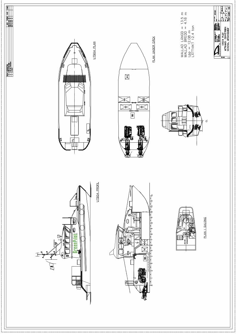

GreenPilot Final Report – v. 20181128 III
Appendix III - SNP15091-707 Hazardous area plan
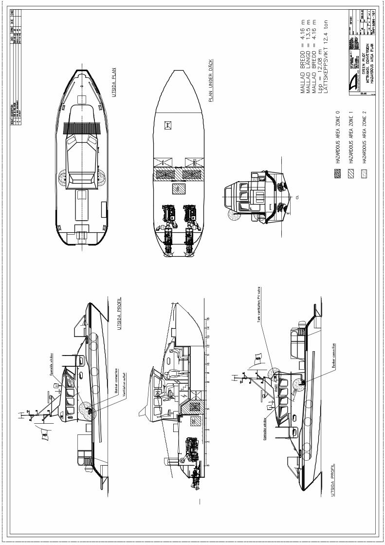

GreenPilot Final Report – v. 20181128 IV
Appendix IV - SNP15091-780 System coordination diagram
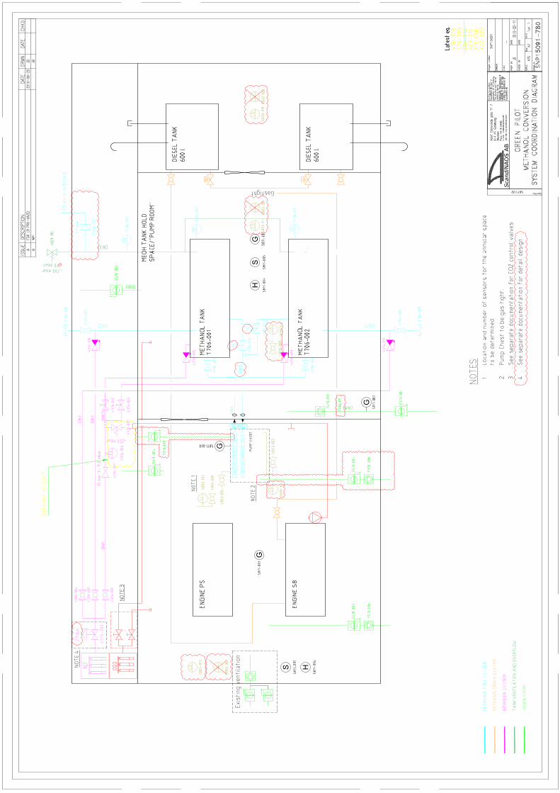
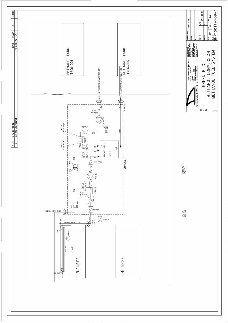

GreenPilot Final Report – v. 20181128 V
Appendix V - SNP15091 - Safety Plan
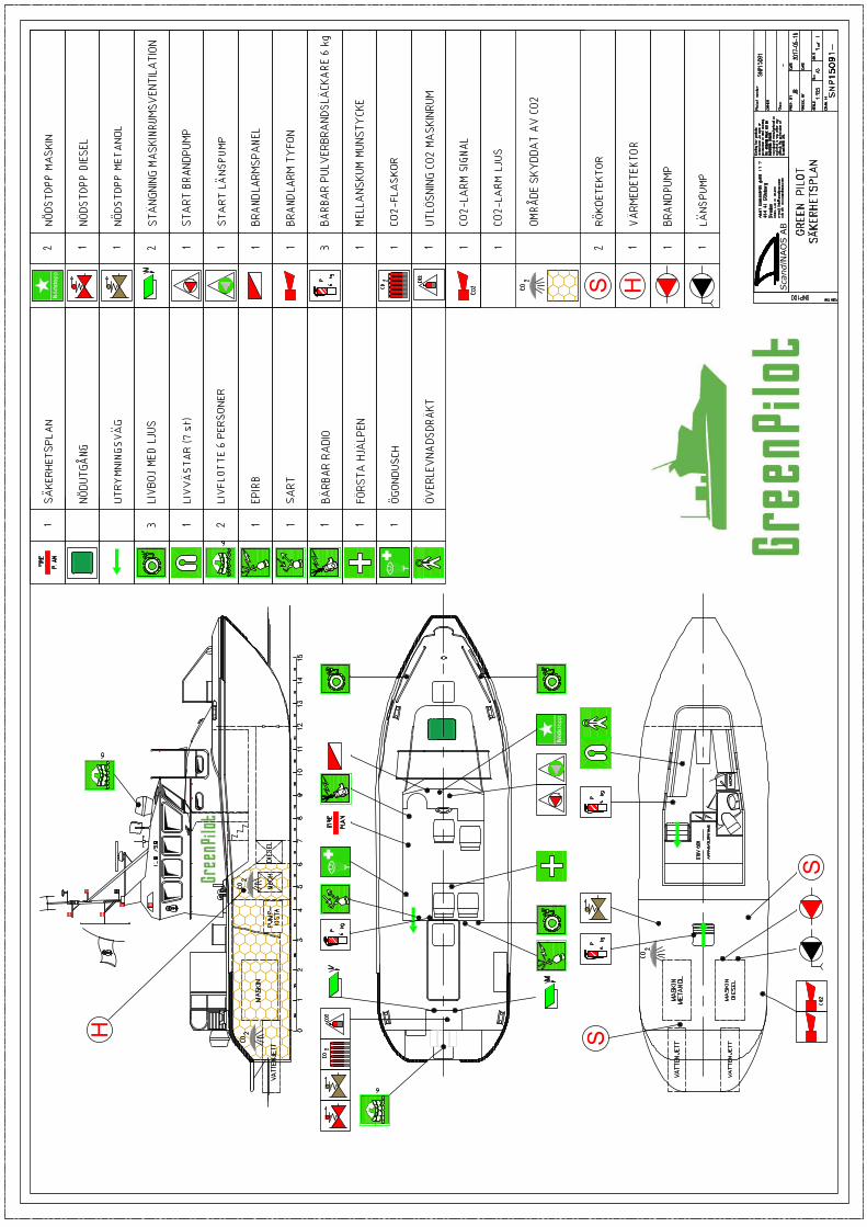

GreenPilot Final Report – v. 20181128 VI
Appendix VI – LR Preliminary HAZID Study
Working together for a safer world
Reference:
CPN 1600521
Reporting date:
11 January 2017
Report by:
Christian Kämmerer
Report
Preliminary HAZID Study for the methanol conversion of Green Pilot
Technical Investigation Department
Report for: ScandiNAOS AB
Rev. No. Date Compiled By Verified By Approved By Reason for Revision
0 11-01-2017 C. Kämmerer M. Heidtmann M. Heidtmann Final report
Report summary
Lloyd's Register EMEA’s Copenhagen Technical Support Office (CTSO) facilitated a preliminary Hazard
Identification (HAZID) Study for the Green Pilot vessel methanol conversion.
The objective of the HAZID Study is to compare the proposed design with the existing rules for
methanol, and analyse the design to identify any reasonably and foreseeable hazards.
The proposed design and safeguards were considered, and a list of findings and recommendations are
compiled throughout the workshop and listed in section 4.
Written by: Approved by :
Christian Kämmerer, M.Sc. Mogens Heidtmann
Signature: Signature:
Designation: Designation:
Senior Specialist Lead Technical Specialist
Date of approval:
13 January 2017
i
Contents
1. Introduction 2
1.1 Background 2
1.2 Objectives 2
2. System Description 3
2.1 Methanol installation 3
3. Preliminary HAZID Study 4
3.1 Study Methodology 4
3.2 Study Assumptions 4
3.3 Preliminary HAZID Nodes 5
3.4 Sessions and Timings 6
3.5 Team Members and Attendance 6
3.6 Preliminary HAZID Study 7
3.7 Worksheet 7
4. Conclusions and Recommendations 11
5. Appendix 12
5.1 Drawings & Documents 12
5.2 Rules 12
2
1. Introduction
1.1 Background
ScandiNAOS is the designer for the conversion of one of the engines of the Green Pilot vessel to methanol
operation.
As the vessel has two independent main engines, the methanol system is not considered essential service.
Lloyd’s Register (LR) has been commissioned by ScandiNAOS to conduct a preliminary Hazard Identification
(HAZID) study for the proposed methanol installation on the Green Pilot.
1.2 Objectives
The objectives of the preliminary HAZID are:
to compare the proposed methanol system design with the existing methanol rules
to identify potential hazards and the proposed safeguards & control measures
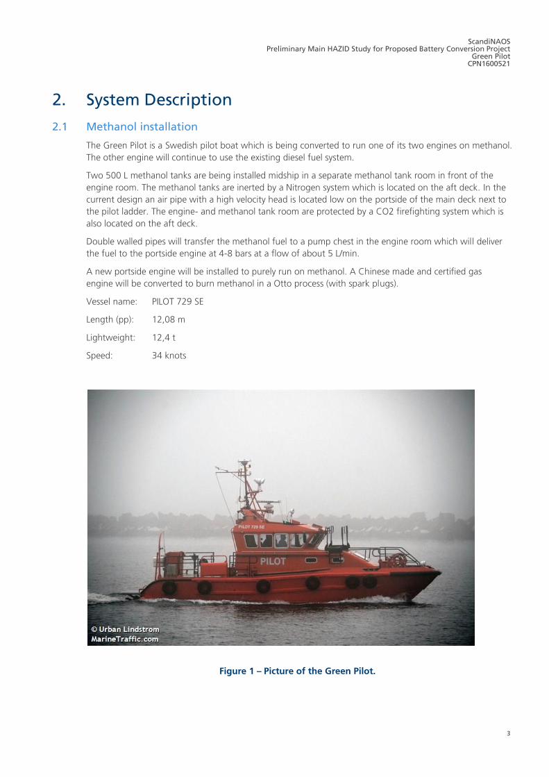
ScandiNAOS Preliminary Main HAZID Study for Proposed Battery Conversion Project
Green Pilot CPN1600521
3
2. System Description
2.1 Methanol installation
The Green Pilot is a Swedish pilot boat which is being converted to run one of its two engines on methanol.
The other engine will continue to use the existing diesel fuel system.
Two 500 L methanol tanks are being installed midship in a separate methanol tank room in front of the
engine room. The methanol tanks are inerted by a Nitrogen system which is located on the aft deck. In the
current design an air pipe with a high velocity head is located low on the portside of the main deck next to
the pilot ladder. The engine- and methanol tank room are protected by a CO2 firefighting system which is
also located on the aft deck.
Double walled pipes will transfer the methanol fuel to a pump chest in the engine room which will deliver
the fuel to the portside engine at 4-8 bars at a flow of about 5 L/min.
A new portside engine will be installed to purely run on methanol. A Chinese made and certified gas
engine will be converted to burn methanol in a Otto process (with spark plugs).
Vessel name: PILOT 729 SE
Length (pp): 12,08 m
Lightweight: 12,4 t
Speed: 34 knots
Figure 1 – Picture of the Green Pilot.
4
3. Preliminary HAZID Study
A preliminary HAZID Study is a methodical ‘creative brainstorming’ technique used to identify hazards and
operational issues associated with a design or process at an early stage.
3.1 Study Methodology
A Structured Checklist technique shall be used based upon LR experience with guidance from the following
sources:
BS ISO 31000: 2009, Risk Management – Principles and Guidelines
BS ISO 31010: 2010, Risk Management – Risk Assessment Techniques
The HAZID node, operation conditions and failure modes used to initiate and encourage discussions are
shown in
Table 1. For each node, possible causes and consequences were discussed. These prompts were based
upon previous experience (and were not considered an exhaustive list) but indicative of the types of hazards
that were thought to be applicable for such a design.
Risk mitigation and reduction measures were discussed, with a focus on elimination of the risk through an
inherently safer design. All items discussed are listed in the worksheet.
3.2 Study Assumptions
A number of assumptions are generally made when completing a HAZID Study of this type. For this project
these included:
The installation and general layout are in line with the drawings and documentation provided.
Where relevant, reference was made to existing rules during the meeting. It was taken into
consideration that the vessel does not have to comply with the existing methanol rules, as it is below
SOLAS and MARPOL minimum sizes (< 400 GT).
As the vessel has two independent engines, and only one is using methanol, the methanol installation is
not considered as essential service for the vessel. The pilot vessel will always be able to manoeuvre with
the second diesel engine. So the methanol system for this conversion is only looked at from a safety
point of view and what impact it can have on the rest of the vessel.
All equipment and materials are suitable for the operating conditions & environment.
ScandiNAOS Preliminary Main HAZID Study for Proposed Battery Conversion Project
Green Pilot CPN1600521
5
3.3 Preliminary HAZID Nodes
The following nodes were suggested to encourage free discussion during the preliminary HAZID Study,
which may prompt the requirement for additional deviations during the workshop.
Equipment & Location
Methanol tank room and fire insulation
General arrangement
Methanol pump chest
Methanol piping
Operation modes
Sailing, normal operations
Sailing in heavy weather
Sailing, methanol system not working
Bunkering
Failures Methanol leakage in tank, pipes or valves
Fire
Table 1 – Preliminary HAZID Study Nodes.
6
3.4 Sessions and Timings
1. Workshop - 22.06.2016
Lloyd’s Register office, Hellerup
10:00 12:00 Discussion
12:00 13:15 Lunch
13:15 14:15 Summary
2. Workshop - 16.11.2016
Lloyd’s Register office, Hellerup
10:15 13:15 Discussion
13:15 13:45 Lunch
13:45 14:00 Summary
Table 2 – Agenda of workshops and time spent.
3.5 Team Members and Attendance
Participants – 1. Workshop
Name Company Role & Title
Christian Kämmerer Lloyd’s Register Facilitator
Risk and Methanol Senior Specialist
Paul Herbert Lloyd’s Register Subject Matter Expert
Mechanical Engineer, piping
Jacob Plum Lloyd’s Register Subject Matter Expert
Electrical Engineer
Mogens Heidtman Lloyd's Register Subject Matter Expert
Fire and safety
Bengt Ramne ScandiNAOS AB Naval Architect
Joakim Bomanson ScandiNAOS AB Naval Architect
Patrik Molander ScandiNAOS AB Naval Architect
Participants – 2. Workshop
Name Company Role & Title
Christian Kämmerer Lloyd’s Register Facilitator
Risk and Methanol Senior Specialist
Paul Herbert Lloyd’s Register Subject Matter Expert
Mechanical Engineer, piping
Jacob Plum Lloyd’s Register Subject Matter Expert
Electrical Engineer
Bengt Ramne ScandiNAOS AB Naval Architect
Joakim Bomanson ScandiNAOS AB Naval Architect
Patrik Molander ScandiNAOS AB Naval Architect
Table 3 – Team members and attendence.
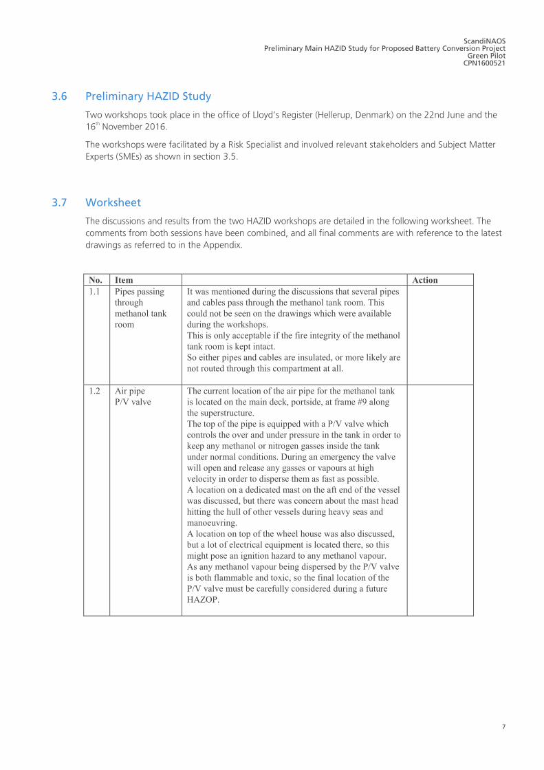
ScandiNAOS Preliminary Main HAZID Study for Proposed Battery Conversion Project
Green Pilot CPN1600521
7
3.6 Preliminary HAZID Study
Two workshops took place in the office of Lloyd’s Register (Hellerup, Denmark) on the 22nd June and the
16th November 2016.
The workshops were facilitated by a Risk Specialist and involved relevant stakeholders and Subject Matter
Experts (SMEs) as shown in section 3.5.
3.7 Worksheet
The discussions and results from the two HAZID workshops are detailed in the following worksheet. The
comments from both sessions have been combined, and all final comments are with reference to the latest
drawings as referred to in the Appendix.
No. Item Action
1.1 Pipes passing
through
methanol tank
room
It was mentioned during the discussions that several pipes
and cables pass through the methanol tank room. This
could not be seen on the drawings which were available
during the workshops.
This is only acceptable if the fire integrity of the methanol
tank room is kept intact.
So either pipes and cables are insulated, or more likely are
not routed through this compartment at all.
1.2 Air pipe
P/V valve
The current location of the air pipe for the methanol tank
is located on the main deck, portside, at frame #9 along
the superstructure.
The top of the pipe is equipped with a P/V valve which
controls the over and under pressure in the tank in order to
keep any methanol or nitrogen gasses inside the tank
under normal conditions. During an emergency the valve
will open and release any gasses or vapours at high
velocity in order to disperse them as fast as possible.
A location on a dedicated mast on the aft end of the vessel
was discussed, but there was concern about the mast head
hitting the hull of other vessels during heavy seas and
manoeuvring.
A location on top of the wheel house was also discussed,
but a lot of electrical equipment is located there, so this
might pose an ignition hazard to any methanol vapour.
As any methanol vapour being dispersed by the P/V valve
is both flammable and toxic, so the final location of the
P/V valve must be carefully considered during a future
HAZOP.
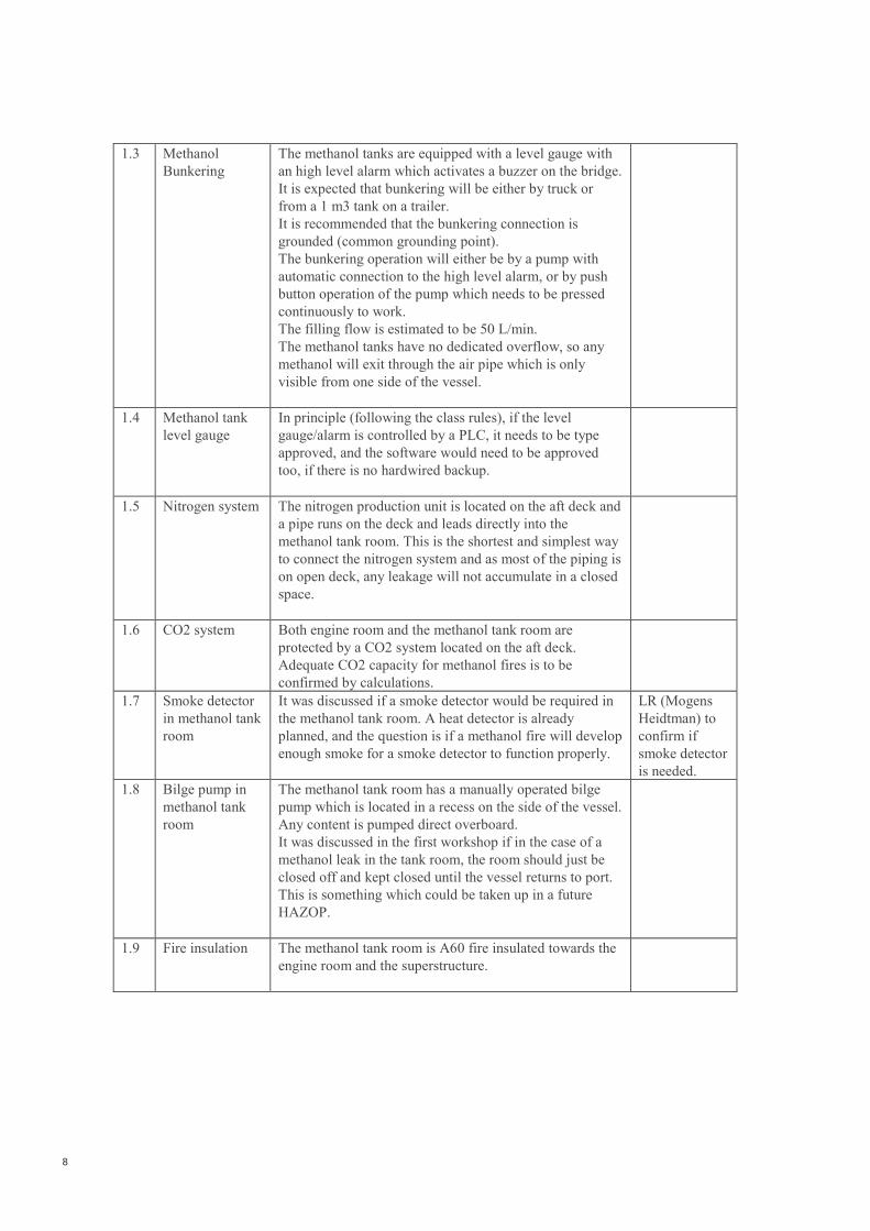
8
1.3 Methanol
Bunkering
The methanol tanks are equipped with a level gauge with
an high level alarm which activates a buzzer on the bridge.
It is expected that bunkering will be either by truck or
from a 1 m3 tank on a trailer.
It is recommended that the bunkering connection is
grounded (common grounding point).
The bunkering operation will either be by a pump with
automatic connection to the high level alarm, or by push
button operation of the pump which needs to be pressed
continuously to work.
The filling flow is estimated to be 50 L/min.
The methanol tanks have no dedicated overflow, so any
methanol will exit through the air pipe which is only
visible from one side of the vessel.
1.4 Methanol tank
level gauge
In principle (following the class rules), if the level
gauge/alarm is controlled by a PLC, it needs to be type
approved, and the software would need to be approved
too, if there is no hardwired backup.
1.5 Nitrogen system The nitrogen production unit is located on the aft deck and
a pipe runs on the deck and leads directly into the
methanol tank room. This is the shortest and simplest way
to connect the nitrogen system and as most of the piping is
on open deck, any leakage will not accumulate in a closed
space.
1.6 CO2 system Both engine room and the methanol tank room are
protected by a CO2 system located on the aft deck.
Adequate CO2 capacity for methanol fires is to be
confirmed by calculations.
1.7 Smoke detector
in methanol tank
room
It was discussed if a smoke detector would be required in
the methanol tank room. A heat detector is already
planned, and the question is if a methanol fire will develop
enough smoke for a smoke detector to function properly.
LR (Mogens
Heidtman) to
confirm if
smoke detector
is needed.
1.8 Bilge pump in
methanol tank
room
The methanol tank room has a manually operated bilge
pump which is located in a recess on the side of the vessel.
Any content is pumped direct overboard.
It was discussed in the first workshop if in the case of a
methanol leak in the tank room, the room should just be
closed off and kept closed until the vessel returns to port.
This is something which could be taken up in a future
HAZOP.
1.9 Fire insulation The methanol tank room is A60 fire insulated towards the
engine room and the superstructure.
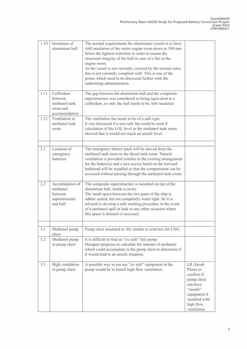
ScandiNAOS Preliminary Main HAZID Study for Proposed Battery Conversion Project
Green Pilot CPN1600521
9
1.10 Insulation of
aluminium hull
The normal requirements for aluminium vessels is to have
A60 insulation of the entire engine room down to 300 mm
below the lightest waterline in order to ensure the
structural integrity of the hull in case of a fire in the
engine room.
As the vessel is not currently covered by the normal rules,
this is not currently complied with. This is one of the
points which need to be discussed further with the
authorising administration.
1.11 Cofferdam
between
methanol tank
room and
accommodation
The gap between the aluminium hull and the composite
superstructure was considered as being equivalent to a
cofferdam, so only the hull needs to be A60 insulated.
1.12 Ventilation in
methanol tank
room
The ventilation fan needs to be of a safe type.
It was discussed if a non-safe fan could be used if
calculation of the LOL level in the methanol tank room
showed that it would not reach an unsafe level.
2.1 Location of
emergency
batteries
The emergency battery pack will be moved from the
methanol tank room to the diesel tank room. Natural
ventilation is provided (similar to the existing arrangement
for the batteries) and a new access hatch on the forward
bulkhead will be installed so that the compartment can be
accessed without passing through the methanol tank room.
2.2 Accumulation of
methanol
between
superstructure
and hull
The composite superstructure is mounted on top of the
aluminium hull, inside a cavity.
The small space between the two parts of the ship is
rubber sealed, but not completely water tight. So it is
advised to develop a safe working procedure in the event
of a methanol spill or leak or any other occasion where
this space is drained or accessed.
3.1 Methanol pump
chest
Pump chest insulated to A0, similar to cold box for LNG.
3.2 Methanol pump
in pump chest
It is difficult to find an “ex safe” fuel pump.
Designer proposes to calculate the amount of methanol
which could accumulate in the pump chest to determine if
it would lead to an unsafe situation.
3.3 High ventilation
in pump chest
A possible way to not use “ex safe” equipment in the
pump would be to install high flow ventilation.
LR (Jacob
Plum) to
confirm if
pump chest
can have
“unsafe”
equipment if
installed with
high flow
ventilation.
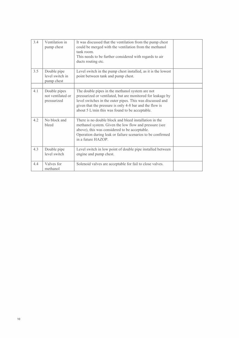
10
3.4 Ventilation in
pump chest
It was discussed that the ventilation from the pump chest
could be merged with the ventilation from the methanol
tank room.
This needs to be further considered with regards to air
ducts routing etc.
3.5 Double pipe
level switch in
pump chest
Level switch in the pump chest installed, as it is the lowest
point between tank and pump chest.
4.1 Double pipes
not ventilated or
pressurized
The double pipes in the methanol system are not
pressurized or ventilated, but are monitored for leakage by
level switches in the outer pipes. This was discussed and
given that the pressure is only 4-8 bar and the flow is
about 5 L/min this was found to be acceptable.
4.2 No block and
bleed
There is no double block and bleed installation in the
methanol system. Given the low flow and pressure (see
above), this was considered to be acceptable.
Operation during leak or failure scenarios to be confirmed
in a future HAZOP.
4.3 Double pipe
level switch
Level switch in low point of double pipe installed between
engine and pump chest.
4.4 Valves for
methanol
Solenoid valves are acceptable for fail to close valves.
ScandiNAOS Preliminary Main HAZID Study for Proposed Battery Conversion Project
Green Pilot CPN1600521
11
4. Conclusions and Recommendations
It was noted during the HAZID Study that a substantial number of issues had already been addressed at the
conceptual design stage of this project based on ScandiNAOS’s experience with earlier methanol projects
(STENA GERMANICA).
At the same time, only limited information about all the vessels systems was available at the time of the
workshop (see drawings list in the Appendix), including info about the engines methanol system.
It was often discussed which existing methanol rules can be used for such a small vessel. The risk of
methanol was often compared to the risk of using gasoline on other vessels of similar size.
The following key items were identified during the HAZID workshops:
Location of the p/v valve for the methanol tank should be carefully considered.
Ventilation and ex safe requirements for the pump chest need to be further considered.
Ventilation requirement in the methanol tank room to be confirmed.
Bunkering operations need to be further considered.
The missing double block and bleed arrangement to be further considered.
The outer pipes of the methanol double pipes to be further considered, as they are not ventilated or
pressurized.
All existing installations need to be included in the modification drawings, as pipes and cables passing
through the methanol tank room were not shown on the current drawings.
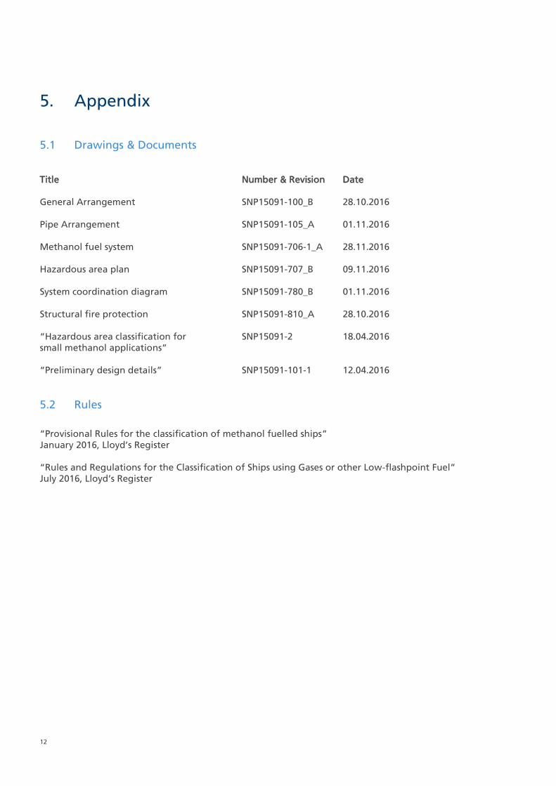
12
5. Appendix
5.1 Drawings & Documents
Title Number & Revision Date
General Arrangement SNP15091-100_B 28.10.2016
Pipe Arrangement SNP15091-105_A 01.11.2016
Methanol fuel system SNP15091-706-1_A 28.11.2016
Hazardous area plan SNP15091-707_B 09.11.2016
System coordination diagram SNP15091-780_B 01.11.2016
Structural fire protection SNP15091-810_A 28.10.2016
“Hazardous area classification for SNP15091-2 18.04.2016
small methanol applications”
“Preliminary design details” SNP15091-101-1 12.04.2016
5.2 Rules
“Provisional Rules for the classification of methanol fuelled ships”
January 2016, Lloyd’s Register
“Rules and Regulations for the Classification of Ships using Gases or other Low-flashpoint Fuel”
July 2016, Lloyd’s Register


C
Christian Kämmerer
Senior Specialist
Lloyd’s Register EMEA
Copenhagen Office,
Strandvejen 104A, 2900 Hellerup, Denmark
T +45 39 48 42 63
W www.lr.org/marine
www.lr.org
Lloyd’s Register Group Limited, its subsidiaries and affiliates and their respective officers, employees or agents are, individually and collectively,
referred to in this clause as ‘Lloyd’s Register’. Lloyd’s Register assumes no responsibility and shall not be liable to any person for any loss,
damage or expense caused by reliance on the information or advice in this document or howsoever provided, unless that person has signed a
contract with the relevant Lloyd’s Register entity for the provision of this information or advice and in that case any responsibility or liability is
exclusively on the terms and conditions set out in that contract.
Lloyd’s Register and variants of it are trading names of Lloyd’s Register Group Limited, its subsidiaries and affiliates.
Copyright © EMEA. 2016. A member of the Lloyd’s Register group.

GreenPilot Final Report – v. 20181128 VII
Appendix VII – Bunker checklist
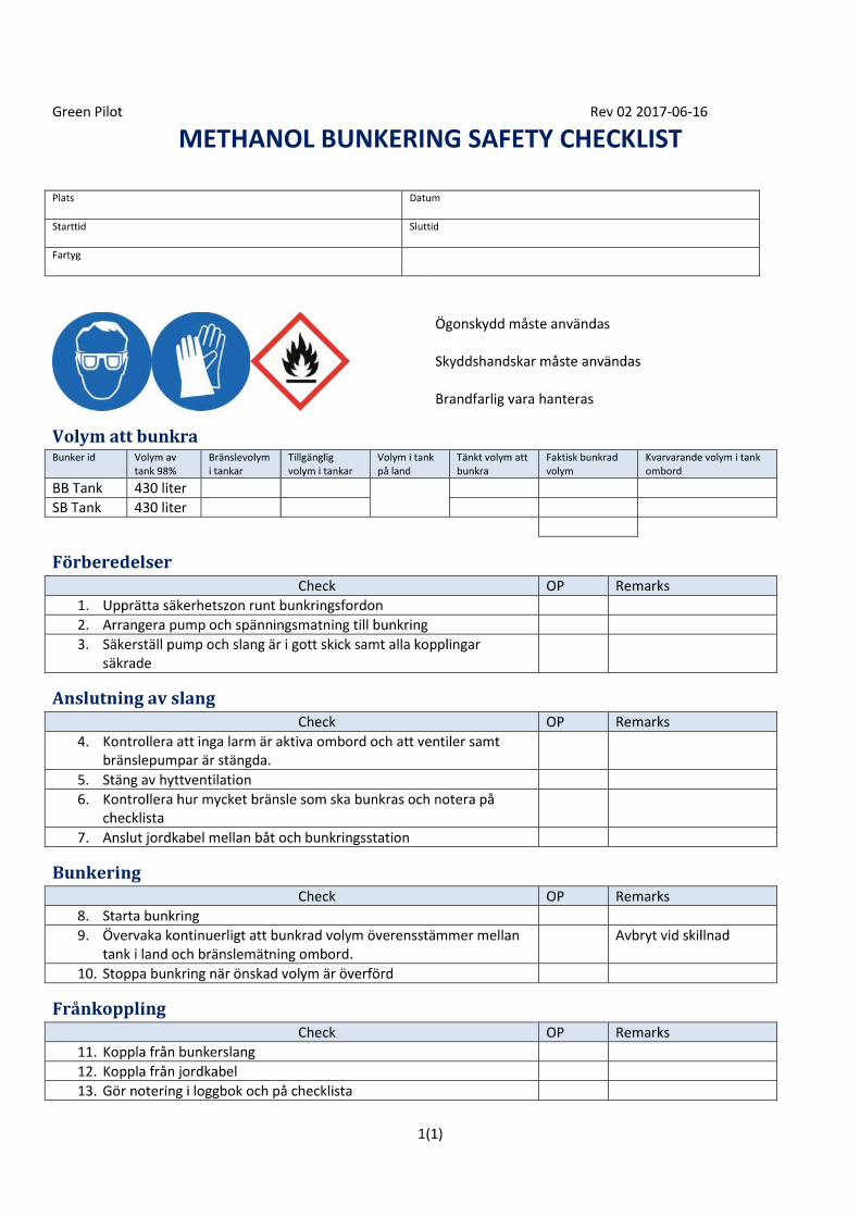


![F-MINIMAL SETS€¦ · The Sturmian minimal sets [9] and the minimal set of Jones [8, 14.16 to 14.24] are F-minimal sets. A discrete substitution minimal set is an F-minimal set if](https://img.pdfslide.us/doc/110x75/6084f15854f7005dbc1e3da1/f-minimal-sets-the-sturmian-minimal-sets-9-and-the-minimal-set-of-jones-8-1416.jpg)