Embed Size (px)
Citation preview

Report No. PUR - 16
PHASE I - FINAL REPORT Exploration of Jovian Atmosphere Using Nuclear Ramjet Flyer
George Maise, James R. Powell and John Paniagua Plus Ultra Technologies, Inc.
and
Robert LecatCenterport, New York
November 30, 2000
Note: The work reported on in this Final Report was performed for Universities SpaceResearch Association (USRA) under NIAC Phase 1 Grant 07600-054, PrimeContract Number NAS5-98051. The period of performance spanned six months;from May 1 though October 31, 2000.
PLUS ULTRA TECHNOLOGIES, Inc.25 East Loop Road
Stony Brook, New York, 11790-3Table of Contents

Table of Contents . . . . . . . . . . . . . . . . . . . . . . . . . . . . . . . . . . . . . . . . . . . . . . . . . . . . . . . . . . . i
List of Figures . . . . . . . . . . . . . . . . . . . . . . . . . . . . . . . . . . . . . . . . . . . . . . . . . . . . . . . . . . . . . . ii
Abstract . . . . . . . . . . . . . . . . . . . . . . . . . . . . . . . . . . . . . . . . . . . . . . . . . . . . . . . . . . . . . . . . . . iii
1. INTRODUCTION . . . . . . . . . . . . . . . . . . . . . . . . . . . . . . . . . . . . . . . . . . . . . . . . . . . . . 1
2. BRIEF HISTORY OF EARLIER WORK ON NUCLEAR RAMJETS . . . . . . . . . . . . . 2
3. PRELIMINARY DESIGN OF RAMJET FLYER . . . . . . . . . . . . . . . . . . . . . . . . . . . . . 2
3.1 Flyer Configuration . . . . . . . . . . . . . . . . . . . . . . . . . . . . . . . . . . . . . . . . . . . . . . . . . 23.2 Packaging of ramjet Flyer in Jovian Entry Capsule . . . . . . . . . . . . . . . . . . . . . . . . . . 43.3 Separation of Flyer from Entry Capsule . . . . . . . . . . . . . . . . . . . . . . . . . . . . . . . . . . 5
4. DESIGN OF NUCLEAR RAMJET ENGINE . . . . . . . . . . . . . . . . . . . . . . . . . . . . . . . . 6
4.1 General Description of MITEE Engine . . . . . . . . . . . . . . . . . . . . . . . . . . . . . . . . . . 64.2. Neutronic Analysis . . . . . . . . . . . . . . . . . . . . . . . . . . . . . . . . . . . . . . . . . . . . . . . . . 74.3 Thermal-Hydraulic Analysis . . . . . . . . . . . . . . . . . . . . . . . . . . . . . . . . . . . . . . . . . 10
5. FLIGHT ENVELOPE IN THE JOVIAN ATMOSPHERE . . . . . . . . . . . . . . . . . . . . . 14
6. INSTRUMENT PACKAGE . . . . . . . . . . . . . . . . . . . . . . . . . . . . . . . . . . . . . . . . . . . . 16
6.1 Instruments needed for the mission . . . . . . . . . . . . . . . . . . . . . . . . . . . . . . . . . . . . . 166.2 Shadow Shielding for Instrument Package . . . . . . . . . . . . . . . . . . . . . . . . . . . . . . . 17
7. MISSION ANALYSIS . . . . . . . . . . . . . . . . . . . . . . . . . . . . . . . . . . . . . . . . . . . . . . . . 19
8. CONCLUSIONS . . . . . . . . . . . . . . . . . . . . . . . . . . . . . . . . . . . . . . . . . . . . . . . . . . . . . 19
REFERENCES . . . . . . . . . . . . . . . . . . . . . . . . . . . . . . . . . . . . . . . . . . . . . . . . . . . . . . 20
Appendices
Appendix A PROPERTIES OF JOVIAN ATMOSPHERE . . . . . . . . . . . . . . . . . . . . . . . . A-1

LIST OF FIGURES
Figure 1. Schematic diagram of the ramjet nuclear flyer: Top, Front, and Left Side.
Figure 2. Schematic diagram of the ramjet nuclear flyer: Bottom, Rear, and Section.
Figure 3. Artist’s rendering of the ramjet flyer in flight.
Figure 4. Cross sectional view of wing.
Figure 5. Packaging of ramjet flyer in Jovian entry capsule.
Figure 6. Separation of flyer from entry capsule.
Figure 7. General Description of MITEE engine.
Figure 8. Cross section of core used in the neutronic analysis.
Figure 9. Cross section of a single fuel element.
Figure 10. Ramjet engine stations used for thermal/hydraulic analysis.
Figure 11. Available thrust as a function of altitude.
Figure 12. Dynamic pressure as a function of altitude.
Figure 13. Stagnation temperature as a function of altitude.
Figure 14. Shadow shielding of the instrument packages.

ABSTRACT
We investigated the design, operation, and data gathering possibilities of a nuclear-powered ramjetflyer in the Jovian atmosphere. The MITEE nuclear rocket engine can be modified to operate as aramjet in planetary atmospheres. (Note: MITEE is a compact, ultra-light-weight thermal nuclearrocket which uses hydrogen as the propellant.) To operate as a ramjet, MITEE requires a suitableinlet and diffuser to substitute for the propellant that is pumped from the supply tanks in a nuclearrocket engine. Such a ramjet would fly in the upper Jovian atmosphere, mapping in detailtemperatures, pressures, compositions, lightning activity, and wind speeds, e.g., in the highlyturbulent equatorial zone and the Great Red Spot. The nuclear ramjet could operate for monthsbecause: 1) the Jovian atmosphere has unlimited propellant, 2) the MITEE nuclear reactor is a(nearly) unlimited power source, and 3) with few moving parts, mechanical wear should be minimal.This report presents a conceptual design of a ramjet flyer and its nuclear engine. The flyerincorporates a swept-wing design with instruments located in the twin wing-tip pods (away from theradiation source and readily shielded, if necessary). The vehicle is 2 meters long with a 2 meterwingspan. Its mass is 220 kg, and its nominal flight Mach number is 1.5. Based on combinedneutronic and thermal/hydraulic analyses, we calculated that the ambient pressure range over whichthe flyer can operate to be from about 0.04 to 4 (terrestrial) atmospheres. This altitude rangeencompasses the three uppermost cloud layers in the Jovian atmosphere: 1) the entire uppermostvisible NH3 ice cloud layer [where lightning has been observed], 3) the entire NH4HS ice cloud layer,and 3) the upper portion of the H2O ice cloud layer.

1. INTRODUCTION
The Galileo probe which entered the Jovian atmosphere in 1995 was a great scientific achievement[1]. It provided, for the first time, direct measurement of Jovian atmospheric properties. Because ofthe nature of the probe, atmospheric data was provided at one location on the planet and, at anyparticular altitude, at one instant of time. (It now appears that the probe entered a decidedlynontypical portion of the Jovian atmosphere. The entry location was one of the clearest and driestspots on the planet.) With the ramjet flyer, we remove the restriction of space and time. We cansample the atmosphere at any location within the altitude restrictions of the flyer. We can observetime-dependent behavior since we can return to same location time and again to resample theatmosphere.
The Jovian atmosphere contains many puzzling features. The most famous, of course, is the Great RedSpot (GRS). It appears to be an enormous anticyclone, although its true nature is still unknown [2].In addition, there are many other less famous features that are lacking satisfactory explanations. Forexample, there are the three white oval spots (the size of Mars) near the GRS. There is the highlyturbulent equatorial zone. It is expected that the Jovian flyer, with its enormous mapping capability(both spatially and temporally), could be instrumental in solving these and other riddles.
The project described in this report is aimed at the design, operation, and data gathering possibilitiesof a nuclear-powered ramjet flyer in the Jovian atmosphere. The MITEE nuclear rocket engine canbe modified to operate as a ramjet in planetary atmospheres. MITEE is a compact, ultra-light-weightthermal nuclear rocket which uses hydrogen as the propellant. Its specific impulse is more than twicethat of the best chemical rockets [3]. It is an outgrowth of the Particle Bed Reactor (PBR) which wasinitiated in the mid 1980's by the DOD/SNTP (Space Nuclear Thermal Propulsion) program [4].While the program did not test a full-up engine, low power critical reactor tests were carried out andthe various component hardware developed and tested. Work on the PBR stopped in 1993 when itsmission need disappeared at the end of the Cold War. While the PBR program was technicallysuccessful, the nuclear engine was still too large and heavy to be useful for present day spaceexploration missions. A new compact, ultra lightweight nuclear engine concept, termed MITEE(MInature ReacTor EnginE) was conceived to meet this need. Thus, MITEE is derived from thePBR, with modifications to substantially reduce the weight of the engine, simplify construction, andenhance performance.
To operate as a ramjet, MITEE requires a suitable inlet and diffuser to substitute for the propellantthat is ducted from the supply tanks in a nuclear rocket engine. Such a ramjet would fly in the upperJovian atmosphere, mapping in detail temperatures, pressures, compositions, lightning activity, andwind speeds. The nuclear ramjet could operate for months because: 1) the Jovian atmosphere hasunlimited propellant, 2) the MITEE nuclear reactor is a (nearly) unlimited power source, and 3) withfew moving parts, wear should be minimal. The ramjet is extremely simple and lightweight, withthree components: 1) a diffuser to compress the incoming atmosphere, 2) a heat source to heat thecompressed gas, and 3) an exhaust nozzle to generate thrust. To perform the mapping mission, theflight vehicle must first be transported into the Jovian atmosphere. This is a technically demanding,but by no means impossible, task. We note that on December 7, 1995, the Galileo Probe, having amass of 339 kg (approximately 50% payload and 50% thermal shield), successfully entered the Jovian

atmosphere. In spite of an entry velocity of 47.4 km/s, stagnation temperatures of 15,500EC, and apeak deceleration of 230 g’s, the probe performed flawlessly. The ramjet flyer will essentiallyduplicate the Galileo Probe mission until our entry vehicle has decelerated to about Mach 1.5 (v =1.3 km/s). At that point, the ramjet flyer will detach from the entry vehicle, and the nuclear enginewill commence operation to propel the flyer on its data gathering mission.
From the standpoint of radiation safety, the nuclear ramjet is not hazardous. Until start up of thereactor, which will occur after entry into Jovian atmosphere, the nuclear fuel is not radioactive.During the launch phase (from Earth), safety systems would prevent reactor criticality for allconceivable accident situations.
Although this study has been directed at mapping the Jovian atmosphere, the technology is equallyapplicable for flying in and mapping the atmospheres of Saturn, Uranus and Neptune.
2. BRIEF HISTORY OF EARLIER WORK ON NUCLEAR RAMJETS
For completeness, we give here a brief historical sketch of earlier work on nuclear ramjets. Duringthe period of 1957 - 1964 very extensive development work was carried out in the U.S. on a nuclearramjet powered missile called the SLAM (Supersonic Low Altitude Missile) under the code name ofProject Pluto [5]. This work was sponsored jointly by the U.S. Air Force and the Atomic EnergyCommission. The mission of SLAM was strictly military, i.e., to deliver nuclear bombs on enemytargets. SLAM was designed to fly at near-treetop level (to avoid radar detection) at a Mach numberof 3. It was powered by the Tory nuclear engine designed at the Livermore National Laboratory.In 1961 a full-sized static test of the Tory engine was conducted in the Nevada desert. The test wasentirely successful, producing 513 Megawatts of power and 35,000 pounds (156,000 newtons) ofthrust. No flight tests were ever conducted. In 1964 Project Pluto was canceled because the ICBMsbecame more attractive as strategic weapons. We have conducted a rather extensive literature survey of the work on Project Pluto. A largecollection of (now) unclassified publications is available in the open literature. This published work,however, is only peripherally applicable to our design. The mission, as well as, the engine andvehicle designs are all very different from ours. (In SLAM, the fission heat is carried to the ramjetengine by an intermediate heat exchanger.) Project Pluto did demonstrate, however, that with aproperly focused development program, nuclear ramjets are practical and will perform as intended.
3. PRELIMINARY DESIGN OF RAMJET FLYER
3.1 Flyer Configuration
The major design drivers for the vehicle configuration are the mass and size of the MITEE nuclearreactor and the payload which, of course, is the instrumentation package. We chose the smallestpossible engine that would go critical with U-235 fuel and with a lithium hydride moderator. Thisengine is cylindrical in shape with a both the diameter and the length equal to about 50 cm. The mass

of this engine of 100 kg. The instrument package mass was taken equal to 59 kg. This correspondsto the mass of the instruments carried on the Galileo probe. This mass is probably conservative sincethe Galileo was launched in 1989. (By the time the flyer is ready for launch, advances inminiaturization will most likely have led to lighter instruments.) Since minimizing launch weight isimportant, the flight vehicle design will incorporate light aircraft construction methods and aluminumstructures. (It will be seen later that aerodynamic heating is not an issue for the proposed mission.)
We selected Mach 1.5 as the nominal design speed for the flyer. Considering that atmosphericmapping is its mission, there is no compelling reason to fly over a wide range of Mach numbers.Furthermore, at Mach 1.5 the flyer can circumnavigate Jupiter in 4 days. This speed (M = 1.5) avoidsthe aerodynamic complications of locally transonic flow. At the same time, the Mach number is lowenough so that 1) a simple normal-shock ramjet inlet does not incur excessive pressure losses, and2) the aerodynamic loading on the structure is not very large, permitting flight at altitudes below 1bar.
The ramjet flyer configuration intended to satisfy these requirements is shown in Figures 1 and 2. Anartist’s rendering is shown in Figure 3. We shall describe the individual elements that make up theflight vehicle, starting from the front.
Inlet - The ramjet incorporates a normal shock inlet, i.e., there is no spiked centerbodyprotruding from the inlet. A normal-shock inlet is the simplest and lightest inlet possible. It canoperate over a range of Mach numbers, although at high Mach numbers the pressure recoverybecomes very poor. At our nominal Mach number of 1.5 the recovery efficiency is 90% which isperfectly acceptable. The inlet is followed by a conical diffuser which slows the flow and increasesthe pressure at the reactor inlet. The inlet also contains a ram turbine which is needed to provide on-board power.
On-Board Power Supply - An on-board power supply is necessary to take full advantageof the virtually unlimited duration of flight. Power is required not only for data recording andtransmission but also for control activation and various navigation, control and command functions.Although a turbine-generator power source could be incorporated into the MITEE engine, wedecided that a simple ram turbine, located in inlet duct, would provide a more reliable system. Asillustrated in Figure 1, the ram turbine is mounted on the same shaft as the generator. The whole unitis supported fore and aft by three or four struts. The electrical power is transmitted to theinstruments (in wing-tip pods) by wires that run through the struts and then through the wings. (Itwill be shown later in this report that, under most flight conditions, the amount of energy extractedfrom the gas stream is negligible.)
Nuclear Engine - The nuclear reactor is the heaviest component of the flyer. The“aerodynamic problem” is to achieve a stable configuration by putting the center of gravity forwardof the center of lift by an acceptable margin. The design details of the engine itself are presented inthe next section.
Wing and Control Surfaces - As noted in Figures 1 and 2, the flyer has a high wingconfiguration with the wing swept back at 30E to accommodate the weight distribution . The wing

is mounted on top of the fuselage to place the center of drag above the thrust line and provide somenose up moment to help trim the configuration. The wingspan is 2 meters. The wing itself has aconstant chord with a 10% biconvex profile (see Figure 4). The trailing edge flaps are 25% of thechord length. With such long control chords, control flutter questions are likely. However, it shouldbe possible to place the center of gravity slightly ahead of the elastic axis (the hinge) as shown inFigure 3. No dihedral angle is shown in the illustrations, however, a negative dihedral may be usefulto minimize some roll-yaw phugoid problems. The wing is connected to the inlet plenum structureby the front spar. Remaining loads are mostly moment loads taken by straps or girdle surroundingthe reactor. Lateral stability is provided by wing-mounted fins at the trailing edges of the instrumentpods.
Wingtip Pods - The instruments and guidance system are located in the two pods attachedto the wing tips. This location of instruments has several advantages over other possiblearrangements: 1) Twin wingtip pods would help relieve wing loads and a c.g. forward of the elasticaxis helps open the flutter envelope. Tailored interferences (e.g., faceted geometry of the pods) couldalso increase wing lift. 2) The instruments are placed at an increased distance from the nuclearradiation source, i.e., the MITEE engine, 3) The wingtip location permits potentially wide look anglesand also permits instruments to “view” simultaneously both above and below the flyer, e.g., for netthermal flux measurement. 4) With two instrument pods located approximately 2 meters apart, onecan use stereoscopic instrumentation, e.g., for viewing cloud formations in three dimensions. 5) Apod open base could even allow optical readings without any interference from windows or othertransparencies. Base pressure in the “dead-air” regions behind the wingtip pods is mitigated byproviding louvers on the sides of the wingtip pods which allow ambient atmosphere to flow into thebase region. The position of the louvers is shown schematically in Figure 1. One of the wingtip podsholds the antenna and transmitter for communicating with the relay satellite.
General Layout - To estimate the center of gravity of the vehicle, we tabulated in Table Ithe moments produced by the individual components (Figures 1 and 2) that comprise the vehicle.From this we estimate to center of gravity as:
Configuration c.g. = [Total Weight] / [Sum of Moments] = 25,900/220 = 115 cm
With a center of pressure estimated between Sta 140 to 150 cm, the configuration would be slightlystable with a stability margin of . 25 cm. Something on the order of 40 cm would probably bedesirable considering the short lever arm of the controls. Moving the instrument payload forward(longer pods) and/or increasing the wing sweep (again longer pods) are obvious tradeoffs. The lift-to-drag ratio of even very blunt reentry vehicles is typically ~4 at low supersonic Mach numbers.We assumed an L/D of 5 for the flyer which is considered conservative.
3.2 Packaging of Ramjet Flyer in Jovian Entry Capsule
To perform the mapping mission, the flight vehicle must be safely transported into the Jovianatmosphere. This is a technically demanding, but by no means impossible, task. We note that GalileoProbe, having a somewhat lower mass of 339 kg (approximately 50% payload and 50% thermalshield), successfully entered the Jovian atmosphere. In spite of an entry velocity of 47.4 km/s,

stagnation temperatures of 15,500EC, and a peak deceleration of 230 g’s, the probe performedflawlessly. The ramjet flyer will essentially duplicate the Galileo Probe entry mission until our entryvehicle has decelerated to about Mach 1.5.
Table 1. Moments produced by individual vehicle components.
ComponentWeight
(kg)Arm (From Sta 0)
(cm)Moment(cm-kg)
Forward Duct 5 60 300
Ram Turbine/Generator 20 60 1,200
Batteries & Charging 15 100 1,500
Guidance 10 100 1,000
Controls 15 100 1,500
Radio & Antennae 10 100 1,000
Instruments/Payload 40 130 6,200
Pod Strut 2 140 280
Wing & Flaps 5 140 700
Reactor 100 120 12,000
Total: 220 25,900
It is proposed that the ramjet flyer will enter the Jovian atmosphere in a lenticular capsule (seeFigure 5) similar to the one which transported the Galileo probe. To accommodate the 2 meterlong and 2 meter wingspan vehicle, the diameter of the capsule will have to be about 2.5 meters. This makes it twice the diameter of the Galileo entry capsule. The ramjet flyer, shownschematically in the illustration, will have to be very well cradled to withstand the severe g-forcesduring entry. As in the case of the Galileo probe, the mass of the thermal shield is expected to becomparable to the mass of the payload. Thus, the total mass of our entry vehicle will beapproximately 500 kg. While larger than the Galileo probe, it is not prohibitively massive.
3.3 Separation of Flyer from Entry Capsule
A possible separation scenario is illustrated in Figure 6. The capsule enters the Jovian atmospherein the conventional manner, i.e, with the thermally protected blunt end forward [see Figure 6 (a)]. It will remain in this orientation during the severe aerodynamic heating and deceleration phase.

When the capsule has decelerated to a Mach number somewhat higher than 1.5, a small drogueparachute is ejected from the side of the capsule nearest the aft end of the flyer. This action willrotate the capsule 90E so that the front end of the flyer points downward [see Figure 6 (b)]. Aftera few oscillations, the capsule will assume a steady orientation as shown in the diagram. At thispoint the two halves of the capsule will separate, by means of small explosive charges [see Figure6 (c)], and the ramjet flyer will be exposed to the free stream conditions at Mach 1.5. At thispoint, the control rods in the nuclear engine will be rotated, starting the fission and the heatproduction. Using the horizontal control surfaces the flyer will be maneuvered out of the diveinto level flight to commence its mapping mission.
4. DESIGN OF NUCLEAR RAMJET ENGINE
4.1 General Description of MITEE Nuclear Engine
The compact ultra-light nuclear reactor engine termed MITEE (MIniature ReacTor EnginE) wasoriginally conceived for use in a nuclear rocket for solar system exploration [3]. MITEE heatshydrogen propellant to 3000 K, achieving a specific impulse of 1000 seconds and a thrust-to-weightof 10. Use of nuclear rockets would enable major improvement in ÄV. Because pure H2 propellanthas low molecular weight, the ISP for nuclear rockets is twice that for the best (hydrogen/oxygen)chemical rockets, with a practical limit on mission ÄV of ~22 km/sec. Using nuclear engines, flyby,orbiter, and lander missions require much less time and smaller, cheaper launch vehicles. They alsoenable new, unique missions, such as 1) use of extraterrestrial propellant (e.g., H2 from ice) to returnsamples from distant moons (Europa), asteroids, and comets; and 2) unlimited flight of ramjet probesin planetary atmospheres (Jupiter, Saturn, etc.).
The MITEE engine, suitable for ramjet applications, is shown in Figure 7. MITEE uses cermet fuelsheets instead of the packed beds of fuel particles employed in the PBR. The cermet fuel sheetsconsists of very small UO2 particles imbedded in a refractory metal matrix (e.g., tungsten). Thecermet W/UO2 fuel was developed and tested in the 1960's for the 710 nuclear engine program. Ithas excellent resistance to hydrogen at temperatures of up to at least 3000 K, exhibiting virtually nofuel loss for operating periods of hours and multiple thermal cycles. The cermet fuel has alsodemonstrated the capability to survive very rapid rates of temperature change of ~10,000 K persecond. The MITEE fuel element consists of an annular roll of multiple cermet fuel sheets (e.g., ~20sheets), rolled together to form the annular element. The inner diameter of the annulus is typicallyabout 1 centimeter, with an outer diameter of approximately 3 centimeters.
The propellant (86% H2 - 14% He) flows radially inwards through the ~1 centimeter thick, annularfuel region emerging into the central flow channel at approximately 1500 K. The multiple cermet fuelsheets are perforated with many small holes providing a large surface area per unit volume of fuelelement for heat transfer from the fuel sheet to the coolant.
Another key feature of the MITEE engine is its ability to achieve criticality in a very small andlightweight nuclear assembly. Three design features make this possible: 1) a very efficient and lowmass neutron moderator, namely, Lithium-7 hydride; 2) minimization of flux disadvantage effects in

the heterogeneous core assembly; and 3) use of separated tungsten-184 isotope for the cermet fuelmatrix, rather than natural tungsten Lithium-7 hydride has a hydrogen atom density close to that ofwater, a lower mass density (0.7 g/cm3, compared to 1.0 for water). Furthermore, 7LiH has a muchhigher operating temperature capability (melting point of 950 K) than water. Other metal hydrides,such as ZrH2, could be used in place of 7LiH, but their weight would be much greater. There is alarge stockpile (many hundreds of kilograms) of separated 7Li in the US, produced as a byproductof the US weapons program.
Flux disadvantage effects in MITEE are minimized by using a sufficient number of fuel elements sothat neutronic behavior of the heterogeneous reactor approaches that of a homogeneous assembly,in which the fissile fuel would be incorporated in with the moderator. The 37 fuel element MITEEdesign achieves this goal.
Finally, natural tungsten has a high thermal neutron absorption cross section, 18 barns, compared tothe order of magnitude smaller cross section for tungsten-184, namely 1.8 barns. The use ofseparated tungsten-184 results in a smaller lighter reactor that requires less fissile fuel. Tungsten-184can be produced, and has been proposed for various nuclear applications.
As described in the following sections, the neutronic and thermal/hydraulic analyses for the MITEEengine, were carried out for selected geometries. As with many complex systems, the final design willultimately be arrived at by iterative analysis, combined with practiced engineering judgement.
4.2 Neutronic Analysis
The primary purpose of the neutronic analysis is to assure that the reactor will go critical andproduce fission energy. We assumed several core geometries that appeared “reasonable,” basedon our previous experience with the MITEE nuclear rocket.. For these, we calculated the reactorcriticality (keff) using the MCNP computer code [6]. (Note: MCNP is a neutronics code wherethe acronym stands for Monte Carlo Neutral Particle). The keff must be at least 1 for sustainedfission. In actuality, a value of keff in the range of about 1.07 to 1.10 is desirable for ease ofcontrol of the nuclear reactor.
In order to carry out a neutronic analysis of the proposed ramjet based reactor the followingassumptions will be made:
1) The inlet temperature will be 300 K,2) The outlet temperature will be 1500 K,3) The pressure drop across the reactor will be 10 % of the inlet pressure,4) A series of inlet pressures will be assumed (0.35 MPa - 3.5 MPa), which will be determined by the altitude and velocity of the vehicle, and5) The Mach number in the fuel element outlet duct will be 0.25.
The outlet duct radius is directly proportional to the square root of the reactor power, andinversely proportional to the square root of the propellant outlet density, since the speed of soundand enthalpy rise are essentially constant under the above assumptions. Thus, assuming a series of
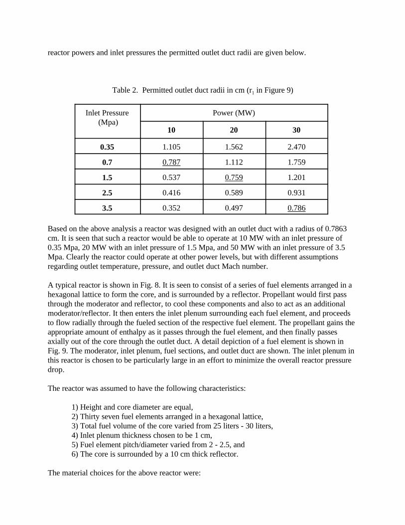
reactor powers and inlet pressures the permitted outlet duct radii are given below.
Table 2. Permitted outlet duct radii in cm (r1 in Figure 9)
Inlet Pressure (Mpa)
Power (MW)
10 20 30
0.35 1.105 1.562 2.470
0.7 0.787 1.112 1.759
1.5 0.537 0.759 1.201
2.5 0.416 0.589 0.931
3.5 0.352 0.497 0.786
Based on the above analysis a reactor was designed with an outlet duct with a radius of 0.7863cm. It is seen that such a reactor would be able to operate at 10 MW with an inlet pressure of0.35 Mpa, 20 MW with an inlet pressure of 1.5 Mpa, and 50 MW with an inlet pressure of 3.5Mpa. Clearly the reactor could operate at other power levels, but with different assumptionsregarding outlet temperature, pressure, and outlet duct Mach number.
A typical reactor is shown in Fig. 8. It is seen to consist of a series of fuel elements arranged in ahexagonal lattice to form the core, and is surrounded by a reflector. Propellant would first passthrough the moderator and reflector, to cool these components and also to act as an additionalmoderator/reflector. It then enters the inlet plenum surrounding each fuel element, and proceedsto flow radially through the fueled section of the respective fuel element. The propellant gains theappropriate amount of enthalpy as it passes through the fuel element, and then finally passesaxially out of the core through the outlet duct. A detail depiction of a fuel element is shown inFig. 9. The moderator, inlet plenum, fuel sections, and outlet duct are shown. The inlet plenum inthis reactor is chosen to be particularly large in an effort to minimize the overall reactor pressuredrop.
The reactor was assumed to have the following characteristics:
1) Height and core diameter are equal,2) Thirty seven fuel elements arranged in a hexagonal lattice,3) Total fuel volume of the core varied from 25 liters - 30 liters,4) Inlet plenum thickness chosen to be 1 cm,5) Fuel element pitch/diameter varied from 2 - 2.5, and6) The core is surrounded by a 10 cm thick reflector.
The material choices for the above reactor were:

1) The fuel in the fuel element consisted of a co-axially wound cermet plate. The fuel along theoutlet duct was assumed to be 184W-UO2 cermet. This fuel is stable over a large temperature rangeand should allow for a wide range of operating conditions. The fuel in the cooler sections of thefuel element was assumed to consist of a Mo-UO2 cermet. Molybdenum has a lower parasiticabsorption cross section than the tungsten isotope (which is the least absorbing of the tungstenisotopes).
2) The moderator consists of a 7LiH-Be composite, which is a good moderator, conducts heatefficiently, has a relatively high decomposition temperature, and is light weight.
3) The reflector is assumed to be primarily inlet coolant augmented by moderator material. Thiscombination is used in order to minimize the reflector mass.
4) The outlet reactor plenum is ignored in this study, thus there is no axial reflectors at the backend of the reactor. Although this assumption is conservative, the real reactor will have minimalaxial reflection at the outlet end.
Three reactor configurations were analyzed using the Monte Carlo code MCNP [6]. This codeuses a combinatorial method of representing the geometry of the system being considered, thus itis possible to include a large amount of detail in the calculation. The results of these threeconfigurations are given below:
Table 3. Possible reactor configurations
Case number 1 2 3
Core volume (liters) 25 25 30
pitch/diameter 2.0 2.5 2.0
r1 (outlet duct) (cm) 0.7863 0.7863 0.7863
r2 (fuel section) (cm) 2.0774 1.9440 2.1949
r3 (inlet plenum) (cm) 3.0774 2.9440 3.1949
Fuel element pitch (cm) 8.3096 9.72 8.7796
Core Dia. And Height (cm) 58.1672 68.04 61.4572
Reactor diameter (cm) 78.1672 88.04 81.4572
Multiplication factor (ke) 0.9878 1.0953 1.0358
Implied power density (MW/liter) - 0.4 - 2.0 0.33 - 1.67
The above results indicate that a core with 25 liters of fuel volume is a possible candidate

configuration. However, a fuel element pitch/diameter ratio of 2.5 is required to achieve anacceptable value for the multiplication factor. This results in a larger core diameter. A smallercore might be possible by increasing the fuel volume and reducing the pitch/diameter ratio (case3), or reducing the inlet plenum thickness (increasing the amount of in-core moderator). Theimplied power densities are relatively modest compared to those proposed for other propulsionreactors [4]. It should thus pose no problem to cool the reactors proposed above. In order toreduce the reactor mass higher power density designs could be investigated, these cores would besmaller, and would thus require a more substantial reflector. Finally, the control system of thereactor will be based on the “venetian blind” concept proposed for the SNTP particle bed reactordesign [4]. This concept is light weight, compact, and can be designed to be hardened againstradiation damage. These options will be explored in the next phase of the study.
4.3 Thermal-Hydraulic Analysis
At this stage the thermal/hydraulic analysis of the ramjet engine is based entirely on one-dimensional flow through the engine. For this purpose we developed a Fortran computerprogram called ENGINE. The properties calculated by ENGINE are: Mach number, pressure,total pressure, temperature, density, sound speed and velocity. The stations at which theseproperties are evaluated are shown in Figure 10. The stations shown correspond to the followingconditions:
Station 1: Free stream atmospheric conditions
Station 2: Conditions after the normal inlet shock
Station 3: Conditions at the end of diffuser which is also the inlet to the reactor core
Station 4: Conditions at the exit from the reactor core
Station 5: Conditions at the nozzle exit plane
The calculational procedure is outlined below. For the Jovian atmosphere (86 % H2 - 14 % He),the values for the gas constant, specific heat and ratio of specific heats, used in the programENGINE are (see Appendix A):
R = 3650 J/kg-K
Cp = 12,100 J/kg-K
ã = 1.428
Station 1 - These conditions are specified by the flight conditions. By selecting thealtitude and flight Mach number in the Jovian atmosphere, we have essentially specified all otherproperties. As stated earlier, the nominal flight Mach number is 1.5. This is used throughout theanalysis (except as noted). The temperature and pressure corresponding to the selected altitude

p2 ' p1 1 %2ã
ã % 1(M 2
1 & 1) (1)
T2 ' T1 1 %2(ã & 1)
(ã % 1)2
ãM 21 % 1
M 21
(M 21 & 1) (2)
ñ2 'p2
RT2(3)
M2 '
1 %ã & 1
2M 2
1
ãM 21 &
ã& 12
2
(4)
c2 ' ãRT2 (5)
V2 ' c2M2 (6)
are found in Appendix A. Note also that the assumption of attached shock, combined with anassumed inlet area, fixes the mass flow rate through the engine.
Station 2 - To reach Station 2, the incoming fluid has to traverse a normal shock wave. We assume that the engine is properly designed so that the normal shock rests exactly on the inletlip, i.e., there is no spillover nor is there a swallowed shock. The post-shock conditions wereobtained from appropriate equations in Liepmann and Roshko [7]. Thus,
and
From these the density is calculated by the perfect gas law,
The post-shock Mach number is given by
The sound speed is given by
And the post-shock flow velocity is

V 22
2%h2 '
V 23
2%h3 %
dWs
dm(7)
A2
A ('
1M2
(2
ã % 1) (1 %
ã & 12
M 22 )
ã % 1ã & 1 (8)
Station 3 - These conditions are reached after traversing the diffuser which also containsthe ram turbine to provide on-board power for instruments, data transmission and vehicle control.The on-board power requirements are estimated as follows:
Instruments (assume same as Galileo) 59 wattsTransmitter (assume same as Galileo) 46 wattsVehicle Control (estimate) 100 watts
The total power required is estimated at 205 watts. Assuming an overall conversion efficiency of40 %, the power extracted from the gas stream in the diffuser is approximately 500 watts.
The control volume energy equation between stations 2 and 3 is given by Shames [8]:
The term dWs/dm is the work done per unit mass of fluid flowing through the system. Choosingthe design point of ambient pressure equal to 1 atm and Mach number = 1.5, the mass flow rate is12 kg/s. This yields the term dWs/dm of 40 J/kg. Comparing this to other terms in the Equation(7), e.g., V2
2 /2 which is 241,000 J/kg, the power extracted from the stream is extremely small andcan be neglected.
For simplicity, we also neglected the wall friction in the diffuser. With this assumption, thecompression is isentropic, and using one-dimensional flow equations, we can readily calculate theconditions at Station 3.
To find the Mach number at Station 3, we need to specify the area ratio of the diffuser A3/A2. For the initial calculations we take the flow area at the downstream end of the diffuser equal to ½of the total reactor frontal area. Furthermore, we shall assume a reasonable diffuser area ratio of2. This fixes the flow areas as follows: A2 = 0.05 m2 and A3 = 0.10 m2.
Since we know M2 and A2, we can calculate the area corresponding to sonic conditions in the gasstream between Stations 2 and 3, by using the following equation:
We determine the A3/A* ratio at the Station 3, i.e., at the downstream end of the diffuser as

A3
A ('
A2
A (
A3
A2
(9)
q ' m )CpÄT ' m )Cp(T4 & T3) (10)
ñ4 'p4
RT4(11)
V4 'm )
A4ñ4(12)
The Mach number at Station 3 can be calculated using again Equation (8). In this case, however,the area ratio (A3/A*) is known and the Mach number is to be determined. Since the equation isnot readily inverted, in ENGINE we determined M3 by a simple trial-and-error iteration. Giventhe Mach number at Station 3 and assuming all the total properties remain constant betweenStations 2 and 3, we can readily calculate all the conditions at Station 3.
Station 4 - This station corresponds to the reactor exit conditions. In traversing fromStation 3 to Station 4 the fluid stream is heated from T3 to 1500 K, i.e., the nominal exittemperature of the reactor. The heat removed by the gas stream is equal to
This quantity is the fission power that must by supplied by the MITEE reactor. For these initialcalculations we make the assumption that the core pressure drop can be neglected, i.e., p4 = p3. (This assumption will be relaxed in a later version of ENGINE. The pressure drop will becalculated for the detailed flow passages in the core.) With the pressure and temperaturespecified at the reactor exit, we can calculate the density
The velocity at Station 5 is given by the conservation of mass equation
Calculating the speed of sound from T4, we can then get the Mach number at Station 4 as M =V4/C4. With Mach number specified, all the properties at Station 4 are defined.
Station 5 - These conditions exist at the nozzle exit plane. The velocity at Station 5determines the thrust that will be produced by the ramjet engine. We assume that the nozzle arearatio is such that the static pressure at Station 5 is exactly equal to the ambient pressure in theatmosphere. Thus, p5 = p1.
Assuming isentropic expansion, there is no drop in total pressure between Stations 4 and 5, andwe have the equality

ptot5
p5
'ptot4
p5(13)
M5 '2
ã & 1(ptot5
p5
)ã & 1
ã & 1 (14)
T5 'Ttot5
1 %ã & 1
2M 2
5(15)
V5 ' M5C5 ' M5 ãRT5 (16)
Fx ' V2(ñ2V2A2) & V1(ñ1V1A1) (17)
Fx ' m )(V2 & V1) (18)
The nozzle exit plane Mach number, M5 is calculated as
With the Mach number available, we calculate the static temperature at the exit plane as
and
With the exit velocity V5 specified, we can readily calculate the thrust produced by the ramjetengine. Using the control volume formulation, Shames [8] gives the x-directed force as thedifference between the momentum leaving and entering the control volume. Thus,
For steady flow, ñ1V1A1 = ñ2V2A2 = m’, we have
This completes the description of program ENGINE.
5. FLIGHT ENVELOPE IN JOVIAN ATMOSPHERE
To establish the range of possible flight altitudes with the nuclear ramjet flyer, we conducted a

parametric study using program ENGINE, described in the previous section. Assuming a flightMach number of 1.5, we calculated the available thrust, assuming that the fluid leaving the reactoris at 1500 K. These results are shown in Figure 11. In addition, at the higher altitudes, we alsocalculated the available thrust at flight Mach number of 3.0. Also shown on the same graph is aline showing the drag of the ramjet flyer. The latter was based on the estimated L/D of 5.0 for theflight vehicle. The mass of the flyer, as determined in Section 2 was 220 kg. To support thismass in level flight in the Jovian atmosphere, where the pull of gravity is 2.34 higher than onEarth, requires a lift force L of
L = 220 (kg) × 2.34 × 9.8 (m/sec2) = 5045 N
Since the L/D of the flight vehicle is 5, we calculate that the drag incurred in providing thenecessary lift as
D = L/(L/D) = 5045/5 = 1009 N . 1000 N
Referring to Figure 11, we see that at an altitude of 62 km the available thrust drops below thedrag, indicating that level flight is no longer possible. This is the maximum altitude of the ramjetflyer. If the flight Mach number were increased to 3.0, the maximum ceiling is increased to 72km. The reason that doubling the speed results in only a modest increase in maximum altitude isdue to the fact that a normal-shock inlet becomes quite inefficient at higher Mach numbers. (Thecompression efficiency drops from 0.9 to 0.32 as the Mach number increases from 1.5 to 3.0) Ifit should become necessary to increase the maximum altitude above ~60 km, we would firstredesign the inlet by providing a conical centerbody which provides more efficient oblique-shockcompression. The maximum altitude achievable with the current design is well above the tops ofthe visible clouds .
The lower limit of the altitude envelope is more difficult to determine at this early stage of design.It is expected that this limit will be stipulated by the maximum dynamic pressure (q- loading) thatthe structure can tolerate. In Figure 12 we have calculated the dynamic pressure as a function ofaltitude in the Jovian atmosphere for flight at our nominal Mach number of 1.5. As we have notperformed a structural analysis on our flight vehicle, it is difficult to set a definite limit. We canmake the following observations, however. First, since it is extremely important to minimize themass of the flyer, there is an obvious limit to the robustness of the structure that is possible. Toprovide a frame of reference, on the top of Figure 12 we show the various q-loadings that wouldbe encountered during sea level flight on Earth at various Mach numbers. Sea level flight at Mach3 would result in a very considerable stress level in the structure. This q-loading wouldcorrespond to flight at Mach 1.5 in the Jovian atmosphere at an altitude of -40 km. Thecorresponding ambient pressure is 4 bars. This pressure is considerably lower than the pressure atwhich the Galileo probe ceased operation, i.e., 24 bars.
One may attempt to lower the dynamic pressure by flying at a lower Mach number. Since aramjet engine can only operate at high subsonic or supersonic speeds, there is clearly a lower limitfor the speed at which it is possible to fly our vehicle. We have calculated the q-loading at Mach1.2 as shown in Figure 12. We note that this would permit flight at about 10 km lower into the

Jovian atmosphere. The corresponding ambient pressure is 5 bar.
With regard to aerodynamic heating, there does not appear to be any impact on the ramjet flyer. At higher elevations, the ambient temperature tends to be very cold by terrestrial standards. Atlower altitudes, where the temperature increases very appreciably our flight is excluded by theexcessive q-loading. Figure 13 shows both the ambient and stagnation temperatures as a functionof altitude. Since we will not be able to fly below -40 km, the maximum structural temperaturecannot exceed 360 K (87EC) due to aerodynamic heating. Thus, from the thermal standpoint,conventional aircraft construction materials are suitable for the flyer.
To summarize this section, we established the approximate altitude range of the flyer from -40 to+60 kilometers. What does this mean in terms of interseting features in the Jovian atmosphere? Referring to Morrison and Owen [2], we note that this altitude range encompasses the threeuppermost cloud layers in the Jovian atmosphere: 1) The entire uppermost visible NH3 ice (cloudlayer where lightning has been observed), 2) the entire NH4HS ice cloud layer, and 3) the upperreaches of the H2O ice cloud layer.
6. INSTRUMENT PACKAGE
6.1 Instruments Needed for Mission
It is expected that the ramjet flyer will carry essentially the same instruments as did the Galileoprobe. (The one exception is the Energetic Particle Instrument which was used to measure thehigh energy charged particles outside the Jovian atmosphere. It probably will not be necessary tocarry this instrument on the flyer for a one-time measurement). The instruments to be included inthe flyer, as in the Galileo probe, are designed to determine the following atmospheric parameters:1) pressure, 2) temperature, 3) chemical composition, 4) location of cloud layers, 5) cloud particlesand size distribution, 6) wind velocity, 7) energy from sunlight, 8) energy from deep interior, and8) lightning frequency and energy. We have compiled a list of instruments to be carried on board of the ramjet flyer. As an initialestimate, we assume using instruments similar to those used in the Galileo entry probe [1, 9]. These are tabulated below in Table 4.
As indicated in the table, the total mass of the scientific instruments is 33.4 kg and the total powerconsumption is 59 watts. The power consumption is quite low and can be easily supplied by asmall on-board turbine-generator. There is a need to consider the susceptibility of theseinstruments to long-term radiation damage primarily from the MITEE nuclear reactor, butpossibly also from the exhaust plume and the natural background radiation in the Jovianatmosphere. On the positive side, by the time the ramjet flyer is deployed, it is probable thatlighter, more compact and more radiation tolerant versions of these instruments will becomeavailable.
As mentioned in Section 3, the instruments are located in the wingtip pods. The total volume of

the two pods is comparable to the volume of the Galileo instrument package. The six instrumentswill be distributed between the two pods to balance the weight. The wingtip location ofinstruments is favorable because: 1) The instruments are placed at an increased distance from thenuclear radiation source, i.e., the MITEE engine, 2) The wingtip location permits potentially widelook angles and also permits instruments to “view” simultaneously both above and below theflyer, e.g., for net thermal flux measurement. 3) With two instrument pods located approximately2 meters apart, one can use stereoscopic instrumentation, e.g., for viewing cloud formations inthree dimensions. 4) A pod open base could even allow optical readings without any interferencefrom windows or other transparencies.
Table 4. Instruments carried on the Galileo probe.
Science Instrument Properties Measured Mass ofInstrument
(kg)
PowerConsumption
(watts)
Atmospheric StructureInstrument
Temperature, pressure,density and mean molecular weight
4.1 6
Neutral Mass Spectrometer Chemical composition ofatmosphere
13.3 25
Nephelometer Clouds, solid/liquid particles 4.7 11
Lightning and RadioEmissions Detector/EnergeticParticles Instrument
Lightning and energeticparticles
2.9 3
Helium Abundance Detector Accurate measurement ofhelium/hydrogen ratio
5 1
Net Flux Radiometer Thermal (from interior) andsolar energy
3.4 13
Total: 33.4 59
6.2 Shadow Shielding for Instrument Package
The current design weight of 220 kg for the flyer does not include radiation shielding for theinstrument package. This does not imply that radiation protection is unnecessary. A detailedanalysis of all the instruments, their radiation tolerance, and the shielding requirements will beconducted under the next phase of this project. With this in mind, we present here some of ourpreliminary thoughts on possible shielding configurations for the flyer instruments.
The instrument packages (see Figure 14) are located in the two wing tip pods which are 20 cm

square in cross section and about 40 cm long. These are located approximately 60 cm from thefuselage of the ramjet. An attempt to shield the instruments from the neutrons and gamma-raysleaking from the reactor, located in the fuselage, will be made by attaching a shadow shieldbetween the instrument pod and the fuselage. The shield will be assumed to be in the shape of aplate 20 cm wide and approximately 40 cm long.
In the interest of keeping the mass as low as possible, the shield will be configured as a layeredstructure. The outer layer will be used to shield the gamma-rays, followed by a neutron shield, andif necessary a second gamma-ray shield which might be required to shield secondary gamma-rayscreated in the neutron shield. The gamma-rays leaking from the reactor will be assumed to havean energy of ~ 1 Mev, and the neutron spectrum of the leakage flux will be assumed to cover theentire energy range from fission energies to thermal energies. The gamma-ray shields will beassumed to be lead layers 1 cm thick, and the neutron shields will be assumed to be a boratedpolyethylene layer 5 cm thick. The lead layer should be able to reduce the gamma-ray intensity to0.46 of its initial intensity. The polyethylene is essentially transparent to gamma-rays, and the finallead layer will reduce the remaining gamma-rays by the same amount as the first layer. In addition,there is a geometrical factor which is approximately proportional to the area ratio of the 20 cmdiameter pod subtended by a circle 120 cm in diameter. To first order, this ratio is given by:20/120ð ~ 0.05. Thus, the total attenuation factor for gamma-rays is ~ 0.46×0.46×0.05 . 0.011.If the shield is too heavy then the outer shield can be removed, and the attenuation factor will beapproximately 0.46×0.05 . 0.023.
The neutron attenuation is not easy to estimate, since they must slow down within the shield andthen be absorbed starting at resonance energies and ending at thermal energies. Polyethylene hasan exceptionally high density of hydrogen and has a low mass density (~ 1.0 gm/cc). Thus mixing polyethylene with 10B, which has a thermal capture cross section of 3837 barns, and a resonanceintegral of 1722 barns, neutrons which are slowed down to these energies have a large probabilityof being absorbed. Additionally, the capture of the neutrons results in an alpha particle whichrequires no additional shielding. The only capture which requires shielding at this stage would bethose in the hydrogen of the polyethylene. This capture gamma-ray has an energy of 2.2 Mev, andits intensity is reduced by approximately 50 % by 1 cm of additional lead. The neutrons will besubjected to the same geometrical attenuation as the gamma-rays (~ 0.05). The additionalshielding afforded by the shield will not be made here, and will require an analysis to determine anoptimum thickness.
The approximate mass of the shield proposed above (for two instrument pods) is given in thetable:
Table 5. Masses of shadow shields.
Three-Layer Shield Two-Layer Shield
Outer Lead Shield 18.6 kg 18.6 kg
Polyethylene Shield 10.6 kg 10.6 kg

Inner Lead Shield 18.6 kg -
Total: 47.8 kg 29.2 kg
These shield masses are quite large compared to the overall mass of the flight vehicle. It is quitepossible that these weights can be reduced by limiting the number and thicknesses of the layers bythe use of radiation hardened electronic components. A comprehensive shield design will addressall the above factors, and integrate them into the flight vehicle. This task will be carried out in thenext phase of the program.
In addition to radiation emanating from the nuclear reactor, there are also a natural radiation fields(high-energy charged particles) around Jupiter which may affect the instruments. This effect willbe of much greater concern for the Jupiter relay satellite than the flyer since the particle fluxes aregreatly attenuated by the Jovian atmosphere [10].
7. MISSION ANALYSIS
The mission analysis depends very much on the type of rocket engine that is available for travel fromLEO to Jupiter. If a chemical rocket is used, the mission will parallel very nearly the Galileo mission.After several gravity assists, the probe will arrive at Jupiter in about seven years. A more likelyscenario is that, if the U.S. develops the MITEE engine for the ramjet application, it will also developa rocket version in parallel. With a MITEE rocket engine, Jupiter can be reached in two years withoutany need for gravity assists.
Powell, et al, [11] analyzed the mission (flight from Earth to Jupiter) of the Jupiter orbiter andatmospheric flyer, using the MITEE nuclear rocket engine. To assure safety, the spacecraft is firstplaced into low Earth orbit (LEO) using conventional chemical rockets. Once stable LEO has beenestablished, the MITEE rocket engine is started and a delta V of 10.8 km/s is imparted to thespacecraft. The spacecraft will reach Jupiter in 2 years. The initial mass in LEO (IMLEO) is 3395 kg,which means that the launch to LEO can be accomplished with a relatively inexpensive Delta II rocket.(Note: Powell’s mission analysis assumed the orbiter and flyer masses at 200 kg and 400 kg,respectively, for a total mission payload of 600 kg. Our more detailed estimate places the flyer mass,with thermal shield, at 500 kg (50% for the flyer and 50% for the thermal shield). This leads to a totalpayload of 700 kg, or 17 % more than used in Powell’s analysis. This increase will, of course, increaseIMLEO, but not enough to make Delta II unusable.)
As was the case with the Galileo probe, we expect to deploy a relay satellite in Jovian orbit to facilitatecommunication between Earth and the ramjet flyer. To perform the mapping mission, the flightvehicle must be safely transported into the Jovian atmosphere. This is a technically demanding, butby no means impossible, task. We note that the Galileo Probe, having a somewhat lower mass of 339kg (approximately 50% payload and 50% thermal shield), successfully entered the Jovian atmosphere.The ramjet flyer will essentially duplicate the Galileo Probe entry mission until our entry vehicle hasdecelerated to about Mach 1.5 (v = 1.3 km/s). At that point, the ramjet flyer will detach from the entryvehicle (see Section 3.3), and the nuclear engine will commence operation to propel the flyer at a

speed of about Mach 1.5.
8. CONCLUSIONS
1. Based on analysis carried out so far, it appears that a nuclear ramjet flyer is a feasibleconcept for mapping in detail the properties in the upper Jovian atmosphere.
2. The ramjet flyer has virtually unlimited duration and provides a unique tool for mapping indetail Jovian atmospheric properties, both spatially and temporally.
3. This data should be useful in helping to elucidate the poorly understood features of theJovian atmosphere, e.g., the Great Red Spot.
4. Although this paper was devoted to mapping the Jovian atmosphere, it can readily beextended to other planetary atmospheres.
5. Additional work is needed in several areas. These include a detailed study of radiationeffects on instruments, flight stability of the vehicle in the highly turbulent Jovianatmosphere, data storage and transmission system, and optimization of the integratedreactor/ramjet/airframe.
REFERENCES
1. Aichele, J.H., Ed., “Galileo, The Tour Guide and a Summary of the Mission to Date,” JetPropulsion Laboratory, JPL D-13554, June 1996.
2. Morrison, D. And Owen, T., The Planetary System, Second Edition, Addison-Wesley,Reading, Massachusetts, 1996.
3. Powell, J.R., et al, “High Performance Nuclear Thermal Propulsion System for Near TermExploration Missions to 100 A.U. and Beyond,” Acta Astronautica, vol. 44, no. 2-4,January-February, 1999.
4. Ludewig, H., et al, “Design of Particle Bed Reactors for the Space Nuclear ThermalPropulsion Program”, Progress in Nuclear Energy, Vol. 30, No. 1, pp 1-66, 1996.
5. Herken, G, “The Flying Crowbar,” Air & Space Magazine, vol. 5, no. 1, April/May 1990.
6. Breimeister, J.F. (Ed.), “MCNP4B2 ; Monte Carlo N-Particle Transport Code System,”Los Alamos National Laboratory, Los Alamos, NM., Report LA-12625-m, 1997.
7. Liepmann, H.W. and Roshko, A., Elements of Gasdynamics, John Wiley & Sons, NewYork, 1957.

8. Shames, I.H., Mechanics of Fluids, McGraw-Hill, New York, 1962.
9. Yeates, C.M., et al, “Galileo: Exploration of Jupiter’s System,” NASA SP-479, 1985.
10. Fischer, H.M., et al, “High-Energy Charged Particles in the Innermost JovianMagnetosphere,” Science, v. 272, no. 5263, 10 May 1996.
11. Powell, J.R., et al, “MITEE: An Ultra Lightweight Nuclear Engine for New and UniquePlanetary Science and Exploration Missions,” 49th International Astronautical Congress,Paper No. IAF-98-R.1.01, Melbourne, Australia, Sept. 28 - Oct. 2, 1998.


APPENDIX A
PROPERTIES OF JOVIAN ATMOSPHERE For the purposes of our performance calculations the atmospheric temperatures and pressures inthe Jovian atmosphere were taken from Reference (A-1). They are reproduced here as Figure A-1. These data are a combination of Galileo and Voyager 1 probe measurements. Variations withaltitude of the Jovian atmosphere were taken from actual Galileo probe measurements in thealtitude range of -146 to +21 km. (Note: As there is no natural reference altitude on Jupiter,following other investigators, we take the reference altitude equal to the altitude where theatmospheric pressure is 1 bar.) Above 21 km, the atmospheric temperature is taken fromVoyager 1 radio occulation data.
For the purposes of calculating the performance of the ramjet flyer, we have taken the Jovianatmosphere to be a binary mixture of 86.1 % hydrogen and 13.9 % helium. This hydrogen molefraction was measured by the Galileo entry probe. We have accounted for the trace gases (CH4,NH4 and H2O, which comprise a total of only 0.3 %) by increasing the helium mole fraction from13.6 % to 13.9 %. The effect of this simplification on the ramjet performance is negligible. Basedon this composition, with mean molecular weight of 2.278, we have calculated for mean values:
R = 3650 J/kg-K
Cp = 12,100 J/kg-K
ã = 1.428
REFERENCE
A-1. Gierasch, P.J., “Dynamics of the Atmosphere of Jupiter,” Endeavour, vol. 20, no. 4, p.144, 1996.


![0367 - Jovian Nightmares [CH0367]](https://img.pdfslide.us/doc/110x75/551fa3764a795993108b4ede/0367-jovian-nightmares-ch0367.jpg)