Embed Size (px)
Citation preview
FINAL REPORT
Colorado Advanced Software Institute
NETSIM: A network simulation system for the design and analysis of network survival techniques
Principal Investigator: C. Edward ChowAssociate ProfessorDepartment of Computer Science
University of Colorado at Colorado Springs
Graduate Student: Dianne OuderkirkDepartment of Computer ScienceUniversity of Colorado at Colorado Springs
Collaborating Company: US West Advanced TechnologiesDr. George I. BellMember of Technical StaffRepresentative
Project Title: NETSIM: A network simulation system for the design and analysis of network survival techniques
Principal Investigator: C. Edward Chow, Ph.D.
University: University of Colorado at Colorado Springs
Collaborating Company: US West Advanced Technologies
Representative of Collaborating Company: George I. Bell, Ph.D.
As authorized representative of the collaborating company, I have reviewed this report and approve it for release to the Colorado Advanced Software Institute.
Signature: ________________________________________________
Date:_____________________________________________________
Page i
Table of Contents1. Objective ..................................................................................................................4
2. Approach..................................................................................................................42.1 Definition Phase...................................................................................................................4
2.2 Modelling Phase ..................................................................................................................52.2.1 The network model................................................................................................52.2.2 Performance metrics..............................................................................................62.2.3 Link-based restoration vs. path-based restoration .................................................8
2.3 Design and Analysis Phase ..................................................................................................92.3.1 Related work..........................................................................................................92.3.2 The design and analysis of modified SHN, One Prong, and Two Prong ............11
2.4 Detailed plan for the NETSIM system ..............................................................................11
3. Results....................................................................................................................113.1 Path-based Two Prong distributed network restoration algorithm.....................................11
3.1.1 Two Prong network restoration protocol.............................................................113.1.2 Lessons learned and further improvement directions..........................................13
3.2 Path-based One Prong distributed network restoration algorithm .....................................133.2.1 Lessons learned and further improvement directions..........................................14
3.3 An enhanced implementation of Grover’s SHN. ...............................................................15
3.4 NETSIM simulation system...............................................................................................15
3.5 Simulation Results .............................................................................................................15
4. Evaluation ..............................................................................................................20
5. Intellectual property developed under sponsorship of this grant. ..........................20
6. Technology Transfer section that describes the technology exchange going in both direction between UCCS and the Collaborating Company....................................20
Abstract
The proposed research deals with the development of algorithms and simulation tools forthe design and analysis of network survival approaches. A software simulation systemcalled NETSIM was built to facilitate the construction of network models and the fastdistributed network restoration algorithms. With NETSIM, we have designed andimplemented three distributed network restoration algorithms: Two Prong path-basedrestoration algorithm (Two Prong), One Prong path-based restoration algorithm (OneProng), and a modified version of Grover’s Self-Healing Network (SHN) algorithm(modified SHN). To evaluate the efficiency of these algorithms in terms of spare capacityusage, a front end interface to Bertseka and Tseng’s Relax-III code was implemented tocalculate the optimal spare usage for a given link break. A graphical user interfaceprogram, called nstool, was built to edit the network topology and status. It also providesan easy to use panel to allow user to specify the restoration algorithms and networkparameters for a simulation run. It helps launch the simulation and collects simulationresults. Nstool is integrated with gnuplot to plot the simulation results.
With the NETSIM and the simulators that simulate link-based and path-based restorationalgorithms, the user will be able to compare these different approaches under the samenetwork assumptions. By integrating with the algorithm that generate optimal spare usagefor link break cases, the user can evaluate the efficiency of these heuristic distributedalgorithms in terms of spare usage.
The NETSIM system can assist the network administrators in their network planning andmanagement tasks. Its simulation results can facilitate the network designers to improvethe network reliability and efficiency.
NETSIM Page 1 December 12, 1995
1. ObjectiveThe general objective of the proposed research was to develop a set of algorithms
and a network software library for the design and analysis of reliable, efficient, survivablenetwork systems that provide fast restoration of disrupted traffic, and efficient utilizationof network resources. The network failures to be examined include single link failures,multiple link failures, single node failures and area failures. The objective described herewas slightly different from the original proposal due to the discussion in the kick-offmeeting of the project. Based on the discussion, we have decided to focus on networkrestoration and especially the path-based network restoration approaches.
First, we proposed to perform a literature survey for the related works on networkrestoration. Objective measures was to be defined and used in the comparison of thenetwork restoration methods. The measures include at least: 1) Time required to restoredisrupted traffic to a defined level, 2) Efficiency of restoration in terms of resourcesrequired for a given level of restoration, 3) Efficiency of restoration in terms of being ableto accommodate different priorities of channels and different levels of restoration goals foreach priority class, and 4) Stability of the restoration techniques in terms of mishandledcircuits and abilities to converge to solution without overload or overshoot.
Second, we proposed to build a network model that can simulate different survivablenetwork topology and status. Efficient network restoration algorithms were to be designedfor the network model. This research was based upon the work we have been doing onpath finding algorithms and distributed network restoration algorithms. The theoreticallimits of these survivable network algorithms were to be investigated, and the performanceof existing survivable network algorithms was to be push closer to these limits or new andbetter approaches to be invented. An extensible network simulation system with anenhanced graphic user interface to demonstrate and to compare different algorithms forsurvivable networks was to be built. The performance of the new network restorationalgorithms would be compared with that of the existing network restoration algorithms. Anetwork software library for constructing the network simulation prototype would beimproved during the life of this project, which integrates the basic procedures for pathfinding, message sending, multicasting, broadcasting, data collection, and debugging.
The algorithms and the network simulation prototype created in the proposedresearch would form a technology and knowledge base to enable and facilitate networkdesigners to design reliable, efficient, survivable networks. They would provide networkadministrators with efficient tools to plan or utilize more efficiently the availablebandwidth in the networks and to provide reliable network services to the users.
2. ApproachThe proposed project proceeded with the following three phases:
2.1 Definition Phase
Based on the survey of the general characteristics of survivable networks and ourresearch on restoration techniques, we defined a common terminology and a set ofquantitative measures of restoration performance. [Wrob90][Wu92] provides a goodintroduction to the problems and the solutions.
NETSIM Page 2 December 12, 1995
2.2 Modelling Phase
We defined a network model with the following parameterized variables:
1) Channel type and priority. Channels can be of different types, such as DS-3 or STS-N.The network model should be able to handle various priority classes.
2) working and spare channels on a span. 3) Network routes.4) Time/methods required to detect fault.5) Time/methods required to propagate detection to the end node of a disrupted path
and other points of intelligence.6) Times/methods required for various computational steps in finding reroute chan-
nels.7) Upper limits on number of computational steps which can be achieved per second
in reroute calculations.8) Speeds of transmission, switching, and processing equipments.9) Time/methods required to send the reroute channel information to network ele-
ments that are responsible for establishing the reroute channels.10) Times/methods required to set up reroute channels.11) Times/methods required to verify that reroutes are established.12) Types of signalling channels among network nodes.
The model was constructed to study the performance of the approaches for restoringsingle link failures, multiple link failures, and node/area failures. A generic network fileformat was designed to capture the network topology and status.
2.2.1 The network model
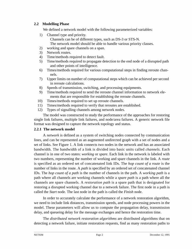
A network is defined as a system of switching nodes connected by communicationlines, and can be represented as an augmented undirected graph with a set of nodes and aset of links. See Figure 1. A link connects two nodes in the network and has an associatedbandwidth. The bandwidth of a link is divided into basic units called channels. Eachchannel is in one of two states: working or spare. Each link in the network is labeled withtwo numbers, representing the number of working and spare channels in the link. A routeis specified as an ordered set of concatenated link IDs. The hop count of a route is thenumber of links in the route. A path is specified by an ordered set of concatenated channelIDs. The hop count of a path is the number of channels in the path. A working path is apath where all channels are working channels while a spare path is a path where all thechannels are spare channels. A restoration path is a spare path that is designated forrestoring a disrupted working channel due to a network failure. The first node in a path iscalled the Start node. The last node in the path is called the Finish node.
In order to accurately calculate the performance of a network restoration algorithm,we need to include link distances, transmission speeds, and node processing powers in themodel. These parameters will allow us to compute the propagation delay, transmissiondelay, and queueing delay for the message exchanges and hence the restoration time.
The distributed network restoration algorithms are distributed algorithms that ondetecting a network failure, initiate restoration requests, find as many restoration paths to
NETSIM Page 3 December 12, 1995
replace the disrupted channels, and issue the connection re-establishment commands tothe involved switching nodes. The restoration time of a network restoration algorithm for agiven network failure, is the period between the detection of the network failure to thetime the last restoration path is connected to the disrupted working path. Given a networkfailure, the restoration level achieved by a network restoration algorithm is the percentagebetween the number of the restoration paths found by an algorithm and the number of thedisrupted working channels affected by the failure. The spare usage of a networkrestoration is the total number of spare channels in the restoration paths found by anetwork restoration algorithm.
2.2.2 Performance metrics
The five major performance metrics we have identified for evaluating NetworkRestoration algorithms are:
1) Time to restoration.
2) Restoration level.
3) Spare usage.
4) Range of application.
5) Message volume.
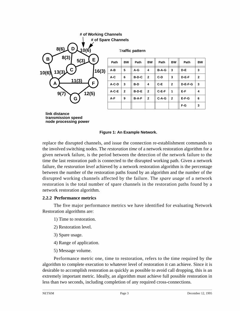
Performance metric one, time to restoration, refers to the time required by thealgorithm to complete execution to whatever level of restoration it can achieve. Since it isdesirable to accomplish restoration as quickly as possible to avoid call dropping, this is anextremely important metric. Ideally, an algorithm must achieve full possible restoration inless than two seconds, including completion of any required cross-connections.
Figure 1: An Example Network.
B
A F
D
E
C
8(6)
8(3)
13(3)
5(3)
10(6)
10(6)
16(3)
11(3)
G12(5)9(7)
# of Working Channels# of Spare Channels
link distancetransmission speednode processing power
Traffic pattern
Path BW Path BW Path BW Path BW
A-B 5 A-G 4 B-A-G 3 D-E 3
A-C 6 B-D-C 2 C-D 3 D-E-F 2
A-C-D 3 B-D 4 C-E 2 D-E-F-G 3
A-C-E 2 B-D-E 2 C-E-F 1 E-F 4
A-F 9 B-A-F 2 C-A-G 2 E-F-G 6
F-G 3
NETSIM Page 4 December 12, 1995
Performance metric two, restoration level, refers to how many of the lost workingchannels are restored. The ideal is that all lost channels be restored. This may not alwaysbe possible. Three situations can occur which limit restoration. The first situation is thatthere is not sufficient spare capacity in the network to support restoration of the lostworking channels, even with an optimal algorithm. Another situation can occur that whilethere is considerable spare capacity within the network, overall, it is distributed in such away that restoration cannot be achieved in a specific failure scenario. Typically, this occurswhen a node adjacent to the link failure has too few spare channels to its other neighborsto restore the lost working channels. Allocation strategies for spare channels is a completearea in itself for research. Certain network topologies can create situations which arepitfalls for distributed algorithms using a heuristic approach to path finding or restorationpath selection (see [WK90]). Such situations can result in the algorithm achieving a lessthan optimal level of restoration.
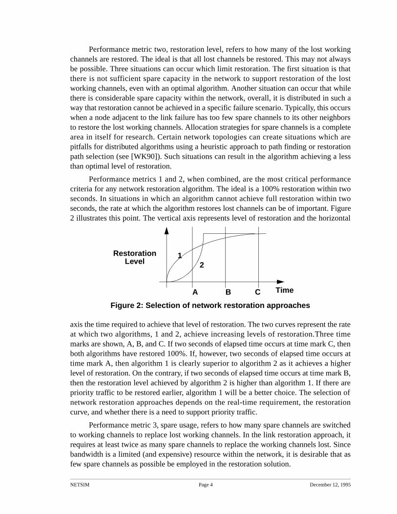
Performance metrics 1 and 2, when combined, are the most critical performancecriteria for any network restoration algorithm. The ideal is a 100% restoration within twoseconds. In situations in which an algorithm cannot achieve full restoration within twoseconds, the rate at which the algorithm restores lost channels can be of important. Figure2 illustrates this point. The vertical axis represents level of restoration and the horizontal
axis the time required to achieve that level of restoration. The two curves represent the rateat which two algorithms, 1 and 2, achieve increasing levels of restoration.Three timemarks are shown, A, B, and C. If two seconds of elapsed time occurs at time mark C, thenboth algorithms have restored 100%. If, however, two seconds of elapsed time occurs attime mark A, then algorithm 1 is clearly superior to algorithm 2 as it achieves a higherlevel of restoration. On the contrary, if two seconds of elapsed time occurs at time mark B,then the restoration level achieved by algorithm 2 is higher than algorithm 1. If there arepriority traffic to be restored earlier, algorithm 1 will be a better choice. The selection ofnetwork restoration approaches depends on the real-time requirement, the restorationcurve, and whether there is a need to support priority traffic.
Performance metric 3, spare usage, refers to how many spare channels are switchedto working channels to replace lost working channels. In the link restoration approach, itrequires at least twice as many spare channels to replace the working channels lost. Sincebandwidth is a limited (and expensive) resource within the network, it is desirable that asfew spare channels as possible be employed in the restoration solution.
21
B
Level Restoration
A Time
Figure 2: Selection of network restoration approaches
C
NETSIM Page 5 December 12, 1995
Performance metric 4, range of application, refers to what different kinds of failurescenarios the algorithm can be applied to affect restoration. A number of the proposeddistributed algorithms can only address single link failures. A limited number ofalgorithms can be used to restore lost working channels in multiple link failure and nodefailure scenarios.
Performance metric 5, message volume, refers to how many network restorationmessages are generated by a restoration algorithm. It is desirable that the number ofmessages an algorithm generates be as few as possible. Not only does message volumeaffect performance metric 1 (time to restore), it also limits other network restorationmessage traffic flow during the restoration process which may be of high or criticalpriority.
It should be noted that we have not included among the performance metrics thenumber of distinct paths an algorithm uses in its restoration solution. Although we havefound a high correlation between the number of paths used in a restoration solution andthe time to restoration metric of a specific algorithm, when comparing across algorithms,this correlation does not exist. As regards the merits, in and of itself, for having fewer orgreater numbers of paths in a restoration solution, we have found no particular benefit toeither one. In general, while we have found some differences among the severalalgorithms in the number of distinct paths which are used in final restoration solutions,they often are the same and reflect more the topology of the network and the location ofthe link failure, rather than the heuristic methods of the algorithms.
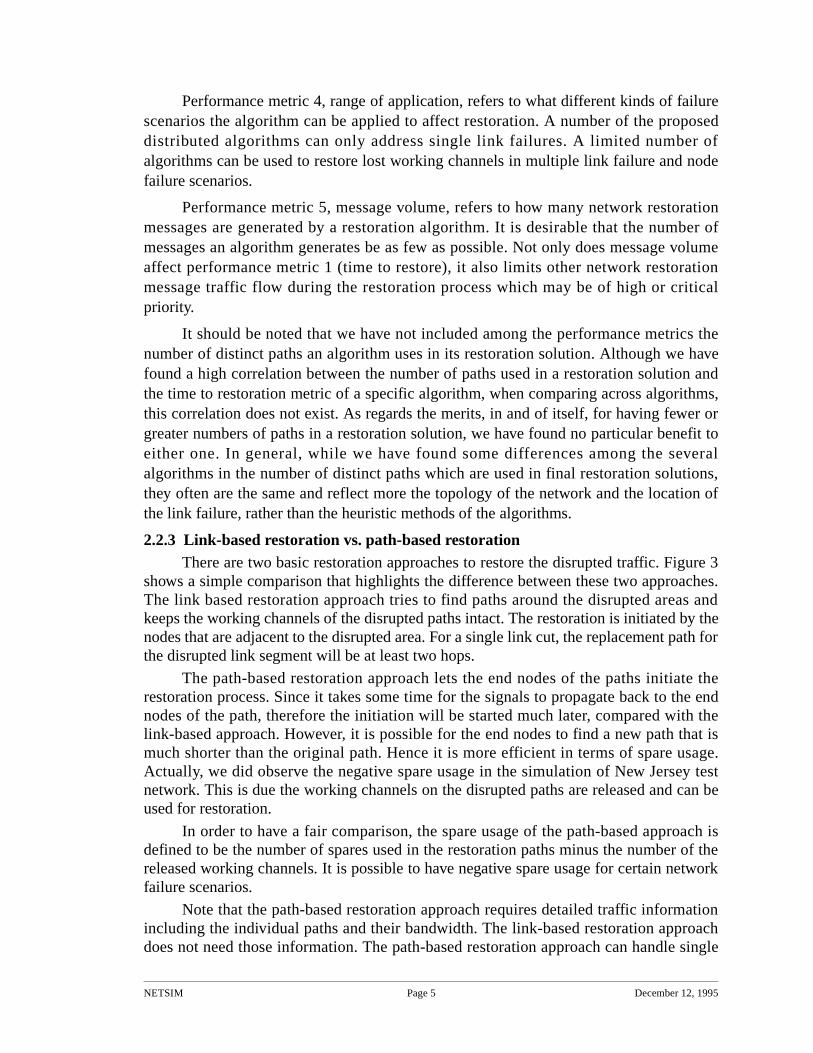
2.2.3 Link-based restoration vs. path-based restorationThere are two basic restoration approaches to restore the disrupted traffic. Figure 3
shows a simple comparison that highlights the difference between these two approaches.The link based restoration approach tries to find paths around the disrupted areas andkeeps the working channels of the disrupted paths intact. The restoration is initiated by thenodes that are adjacent to the disrupted area. For a single link cut, the replacement path forthe disrupted link segment will be at least two hops.
The path-based restoration approach lets the end nodes of the paths initiate therestoration process. Since it takes some time for the signals to propagate back to the endnodes of the path, therefore the initiation will be started much later, compared with thelink-based approach. However, it is possible for the end nodes to find a new path that ismuch shorter than the original path. Hence it is more efficient in terms of spare usage.Actually, we did observe the negative spare usage in the simulation of New Jersey testnetwork. This is due the working channels on the disrupted paths are released and can beused for restoration.
In order to have a fair comparison, the spare usage of the path-based approach isdefined to be the number of spares used in the restoration paths minus the number of thereleased working channels. It is possible to have negative spare usage for certain networkfailure scenarios.
Note that the path-based restoration approach requires detailed traffic informationincluding the individual paths and their bandwidth. The link-based restoration approachdoes not need those information. The path-based restoration approach can handle single
NETSIM Page 6 December 12, 1995
link, multiple links, node and area failures, while the link-based approach cannot handlethe node or area failures.
2.3 Design and Analysis Phase2.3.1 Related work
In [Chow93a] we propose a new fast distributed algorithm based on a Two-Prongedapproach. Unlike the Self-Healing Network [Grover 89] and Bellcore’s FITNESS[Yang88] algorithms, the Two-Prong algorithm does not use a Sender—Chooserrelationship for the nodes adjacent to the fiber link cut to initiate the restoration process.Instead, the two nodes perform nearly symmetrical roles throughout the execution of theTwo-Prong algorithm. Although the Two-Prong approach is the fastest in terms of time torestore, it does require sophisticated backtracking to achieve the higher restoration level.Further development of the Two-Prong approach should succeed in not only reducingsusceptibility to racing conditions, but also improving spare channel resource utilization inthe final restoration solution. One avenue to be explored is an optimization based uponexchanging sub-path connections following a backtracking episode. These exchangeswould preserve the shortest possible paths and reduce connections to longer sub-paths.Such optimization procedures may, however, increase message volume during therestoration process and possibly degrade the time performance of the Two-Prongapproach. Further research is needed to develop efficient optimizations and explore theserelated trade-offs.
In a comparison study of our current implementations of the Two-Prong and theRREACT approaches [Chow93b], we found that on the large US network test model Two-Prong generates fewer messages while on a smaller network such as the New Jersey LATAnetwork the RREACT generates half as many messages. The messages generated by the
BA D
E
C
The link based restoration approach tries to find paths around the disrupted areas and keeps other working channels intact.
BA D
E
C
The path based restoration approach releases the working channels ofthe disrupted paths and has original sources re-establish connections.
released released
Figure 3. link-based restoration vs. path-based restoration
NETSIM Page 7 December 12, 1995
RREACT approach are variable length since they contain path information. The messagesgenerated by Two-Prong are fixed length and shorter than those of RREACT. TheRREACT implementation was able to achieve full restoration on all single-link failures ofthe New Jersey LATA network while Two-Prong fails to achieve full restoration on 6 outof 23 link failure cases. The average level of restoration in the 6 partial restoration cases isaround 86%. The current implementation of Two-Prong tries to minimize the messagelength and the restoration table maintained in each node. One possible improvement onthe Two-Prong is to include additional information in the messages to allow the intelligentbacktracking mechanism to make better decisions. Determining the minimum informationexchange that would allow the faster Two-Prong approach to achieve full networkrestoration is an interesting and challenging research issue.
The RREACT algorithm has also proven to be a very stable, robust algorithm,achieving full restoration in all the single-link failure scenarios on the New Jersey LATAnetwork. Time performance was also excellent, outperforming the FITNESS algorithm inall but one scenario and beating the Two-Prong algorithm in six instances. Spare channelutilization is also excellent, the best of the three algorithms. Unfortunately, our researchhas shown that RREACT’s performance begins to degrade as the network grows in size.This is due to longer message lengths and dramatically increased message volume assolution paths become longer and more numerous in the larger network. We will examinetechniques to improve RREACT’s performance in these larger network scenarios, such assetting time-of-life for the restoration request messages and restricting the hop countswhich the messages can traverse.
Two-Prong has proven to be the fastest of all the algorithms we have implementedand tested. In fact, Two-Prong achieves restoration faster than FITNESS in all instancesand is faster than RREACT in all but six instances. Good time performance remainsconsistent, even as network size increases. Spare channel utilization is better thanFITNESS and nearly as good as RREACT. Message volume appears high in the NewJersey LATA network, but is very stable and does not grow as quickly as RREACT whennetwork size is increased. Unfortunately, the Two-Prong algorithm has proven to be verysusceptible to message racing conditions which affect its performance occasionallyresulting in less than full restoration. Current implementations have restricted messagecontent to preserve fixed length messages and to limit storage and processingrequirements in the individual nodes. Such restrictions inherently require sophisticatedconnection and back-tracking logic for the algorithm to perform correctly in alltopologies. The perfecting of this logic with these constraints has proven to be achallenging and non-trivial research effort.
In [Chow93c] we provide a detailed analysis of the basic factors that impact theperformance of network restoration approaches. These factors include 1) path finding, 2)spare channel contention resolution, 3) restoration paths selection, 4) message volumecontrol, 5) congestion control, 6) race condition control, and 7) paths re-establishmentapproaches. This gives us a systematic way to analyze a network survivable approach inthe proposed project.
As it is indicated in [Chow93d], the existing distributed network restorationapproach perform well in link restoration cases but there is a lot of room for improvementin the node and area failure cases. The major cause of poor performance in node/arearestoration cases is the uncoordinated contention among the requests for different
NETSIM Page 8 December 12, 1995
restoration paths. Strict priority-based contention solution can guarantee the restoration ofpaths in sequential but it will have poor restoration time performance. The major thrust ofresearch effort will be to explore new distributed contention resolutions approaches in thenetwork restoration setting. Examining existing distributed contention resolutions ordeadlock avoidance algorithms in the literature will be a starting point.
2.3.2 The design and analysis of modified SHN, One Prong, and Two ProngModified SHN was implemented by following the PASCAL pseudo code in
Grover’s dissertation and filled in out interpretation of the logic that is not clear specified.We then went through the debugging process to verify the simulation results and improveits performance.
Two Prong extends the idea of link based Two Prong. But with the additional trafficpattern and the need to handle the resource contention among the competing paths, thesoftware for the protocol simulation is completely designed from scratch. We did reuse thediscrete event simulation kernel from previous project.
One Prong was designed with the goal to allow multiple path restoration to coexists.We reuse most of the Two Prong code include the table management routines, but the logicis much simplified.
2.4 Detailed plan for the NETSIM system
NETSIM was built using the algorithms, software libraries, and tools provided bythe Computer-Aided Network Design & Analysis Research Environment, CANDARE,which was developed at UCCS and was used successfully to develop generalized resourceallocation systems. CANDARE facilitated us to construct the network models and todesign the network restoration algorithms. We designed the proposed algorithms with theneeded controllable parameters for modelling the message processing delays, messagetransmission delays, and restoration time, and for collecting the statistics of the objectivemeasures mentioned above.
3. ResultsWe have designed and implemented two versions of path-based distributed network
restoration algorithms. One is based on the Two Prong link-based distributed networkrestoration algorithm. The other is based on a one prong idea with simplified logic. Wealso implemented a version of Grover’s Self-Healing Network and included enhancementto improve the clean up phase. A graphical user interface based on XVIEW was built tofacilitate the editing of network topology and the control of the simulation runs.
3.1 Path-based Two Prong distributed network restoration algorithm
In this section the path-based Two Prong algorithm is briefly introduced.
3.1.1 Two Prong network restoration protocolThe protocol has five phases: Notification Phase, Tentative Connection Set Up
Phase, Path Trace-out Phase, Path Confirmation Phase, and Clean Up Phase.
Notification PhaseOn detecting the network failure, a node broadcasts the network with PACK
messages that identify the paths that are affected and the relative position of the node onthe path, i.e., upstream or downstream relative to the disrupted area. It also forwards FAIL
NETSIM Page 9 December 12, 1995
messages along the path to the end node still connected. The FAIL messages trigger therelease of working channels of the disrupted paths. To reduce the number of messages andthe protocol processing time, one PACK message carries up information up to 10maximum disrupted paths. 10 was chosen based on trials on New Jersey network. Networkwith large number of paths and faster transmission speed may increase the number forbetter performance.
Based on the information in the PACK messages, each node maintains a table thatkeeps track of the upsteam or downstream nodes to a disrupted path.
Tentative Connection Setup PhaseWhen a tandem node receives PACK messages from both the upstream and
downstream nodes related to a particular path, it knows there is a potential restorationpath, sets up tentative connection, and sends CREQ messages to its neighbors along thepotential restoration. The CREQ message will be replied with a CRACK messageindicating the actual number of reserved spares. The exchange of CREQ/CRACKmessages will be propagated to the end node of the path.
Path Trace-out PhaseOn receiving a CREQ message, the Finish node of the path sends an ACK message
upstream and reserves the bandwidth along the way.
On receiving an ACK message, the tandem node updates the table to indicate thepath bandwidth is now reserved and forwards the ACK message upstream. Note that anACK message may be split into several ACK messages with smaller bandwidth request.
In case of resource contention among paths, an ACK message may arrive and findthe previous reserved spare are taken over by the higher priority path. A CONFC messagewill be returned to the sender of the ACK message.
Path Confirmation PhaseOn receiving an ACK message, the Start node sends a CONF message along the
restoration path and confirms the establishment of the restoration path. If all thebandwidth of the path is found, a “Final” flag will be set in the CONF message. TheCONF message with the Final flag is called CONFF message. The reception of any furtherACK message will be replied with an NAK message to tear down the tentativeconnections.
On receiving a CONFF message, the tandem node will release bandwidth that is noton the confirmed path and indicate in its table that the path has restored all its bandwidth.The reception of any further request for the path will be rejected. The CONFF messagesare used by the end node to inform the tandem nodes to stop the bandwidth reservationprocess.
When the Finish node receives CONF message, part or all the bandwidth of a path isrestored.
Clean up PhaseWhen all the bandwidth of a path is restored, a PDONE message is flooded out to
speed up the release of unneeded bandwidth.
NETSIM Page 10 December 12, 1995
3.1.2 Lessons learned and further improvement directionsThe arrival of a CONF message may trigger the release of bandwidth on some
outgoing links and hence the initiation of the pending restoration requests on other paths.Multiple messages were observed to be sent over an outgoing link. One possibleimprovement of Two Prong is to consolidate all the operations in those messages into asingle message. When the protocol processing time is the dominant factor in the totalrestoration time, this message consolidation effort can have a big pay-off.
One of the important protocol parameters is the retrial number of the ACK requests.Allowing the retrial along a rejected path has shown to increase the restoration level insome cases. But in other cases, it not only decreased the restoration level but also sloweddown the restoration process due to the additional message volume. Further research isneeded to decide how many retrials are needed and when to retry.
The hop count limit on the PACK message also impact the restoration level andrestoration time. The original hypothesis, that the larger hop count should yield the higherrestoration level, was proven to be false. In some of the simulation runs, we have observedthat after a certain threshold on the hop count, both the restoration level and the restorationtime went down. This is due to the increase of message volume and racing situations. Alsothe optimal hop counts are not the same for all failure cases.
3.2 Path-based One Prong distributed network restoration algorithm
One Prong was built based on the reuse of Two Prong software and implemented amuch simplified logic. The protocol has only four phases: Notification Phases, Path Trace-out Phase, Path Confirmation Phase, and Clean Up Phase.
Notification PhaseOn detecting the network failure, a node broadcasts the network with PACK
messages. The PACK messages identify the paths that are affected and the relative positionof the node on the path, i.e., upstream or downstream relative to the disrupted area. It alsoforwards FAIL messages along the path to the end node still connected. The FAILmessages trigger the release of working channels of the disrupted paths. To reduce thenumber of messages and the protocol processing time, one PACK message carries upinformation up to 10 maximum disrupted paths.
Based on the information in the PACK messages, each node maintains a table thatkeeps track of the upstream or downstream nodes to a disrupted path.
Path Trace-out PhaseOn receiving a PACK message, the Finish node of the path sends an ACK message
upstream and reserved the bandwidth along the way. The ACK message also carries anACKHOP field that indicated the hop count of its traversed path. When the sum ofACKHOP count and the HOP count field on the table, which was created by the PACKmessage, exceeds the hop count limit, the ACK was rejected with a CONF with zerobandwidth. This cuts down quite a lot of message volume.
To avoid forwarding an ACK message to a node which is its traversed path, a TRAILfield which contains the traversed node list is included in the ACK message.
NETSIM Page 11 December 12, 1995
On receiving an ACK message, the tandem node updates the table indicating thepath bandwidth is now reserved and forwards the ACK message upstream. Note that anACK message may be split into several ACK messages with smaller bandwidth request.
In case of resource contention among paths, an ACK message may arrive and findthat there are not enough spares to satisfy its bandwidth request. If there is no spare left, aCONF with 0 bandwidth is returned. If there are some spares left, a CONFX with theunsatisfied bandwidth of the ACK request is returned.
Path Confirmation PhaseOn receiving an ACK message, the Start node of the path sends a CONF message
along the restoration path and confirms the establishment of the restoration path. If all thebandwidth of the path is restored, a “Final” flag will be set in the CONF message. TheCONF message with the Final flag is called CONFF message. The reception of any furtherACK message will be replied with an NAK message to tear down the tentativeconnections.
On receiving a CONFF message, the tandem node will release bandwidth that is noton the confirmed path and indicate in its table that the path has restored all its bandwidth.The reception of any further request for the path will be rejected. The exchange of CONFFmessages is a mechanism to allow the end node to inform the tandem nodes to stop thebandwidth reservation process.
When the Finish node receives CONF message, part or all the bandwidth of a path isrestored.
Clean up PhaseWhen all the bandwidth of a path restored, a PDONE message is flooded out to
speed up the release of unneeded bandwidth.
3.2.1 Lessons learned and further improvement directionsIn the original Two Prong logic, a node throws away the PACK message that it has
seen before. The early implementation of One Prong follows the same logic. Through thedebugging of a network failure scenario which is supposed to have full restoration, wediscovered that the second PACK message needs to be forwarded (not broadcast) to thesender of the first PACK message to enable the finding of additional restoration paths.
This subtle modification is an evidence of the difficulty of distributed programming.Many subtle modifications on One Prong were based on tedious and long debugging. Thedebugging facility that prints out the simulation events of a selected path or node proved tobe instrumental to those subtle but important improvements in One Prong.
One Prong uses a very conservative approach in finding paths between the Finishnode and the Start node. At any instance of time, the aggregated bandwidth in the ACKmessages does not exceed that of the disrupted path. Only when the ACK message gotrejected, the retrial on other outgoing links will be initiated. The reason here is to allowmore paths to be concurrently restored, since in path-based approach there may bemultiple paths exploring the restoration paths. A more aggressive approach is to use theflooding approach used by most the link-based approach to explore the restoration path.We have done some preliminary study of this aggressive approach and the early simulation
NETSIM Page 12 December 12, 1995
results seems to indicate late restoration time and lower restoration level. But withoutadditional study, this may be premature conclusion.
The current One Prong tries to strike a balance between restoration time andrestoration level. The spare usage is not a major concern. If the goal of the restoration is tohave spare usage as a top priority, restoration level second, and restoration time last, then anew path-based algorithm needs to be designed. One possible design is to wait for thePACK message to arrive from all the possible paths to the Finish node before sending thefirst ACK message. To find out shorter path first, an ACK request follows the bread-firstsearch pattern should be sent. This however does not guarantee the optimal spare usage asit was indicated by [WK90].
3.3 An enhanced implementation of Grover’s SHN.
One of the early efforts of the project was to develop a simulator for Grover’s SHNbefore we shifted our focus on the path-based approach. Based on the description inGrover’s Ph.D. dissertation, we implemented a version of SHN and through debugging weenhanced its clean up phase operation. We observed that the old signature may chase thebandwidth just released by ACK of the same index. The virtual looping will not terminateuntil the old signature exceeds the hop count limit. We modified the logic to have a newsig-cancel event and allow the tandem node to keep a list of signatures that got canceled.We did find the restoration level improvement and the fast convergence in the clean upprocess with this new enhancement. However the problem of when to release thiscancelation list remains to be an open issue.
With this implementation, it allows us to compare the major link-based restorationapproaches with path-based approaches under the same network assumptions.
3.4 NETSIM simulation system
We have built a network restoration simulation system called NETSIM where themajor link restoration approaches, such as the FITNESS, SHN, RREACT, and link-basedTwo Prong were implemented as simulators. We also implemented versions of path-basedTwo Prong and One Prong. These simulators were built with unified command interfacewhere the simulation parameters can be consistent specified. A generic set of simulationparameters include transmission speed, refractive index (related to the propagation delay),message/protocol processing time, hop count, DCS cross connect time, and DCSoperating mode (parallel or sequential).
A set of network file conversion utilities was built to convert other network fileformats to that of NETSIM. These utilities also generate the script files with commandsthat simulate each of the link breaks and node failures with default simulation parameters.Simulation with different simulation parameters can be carried out by modifying thesescript files.
A graphical user interface called nstool was built that can edit the network topology,launch multiple simulation, collect simulation results, and display them using gnuplot.
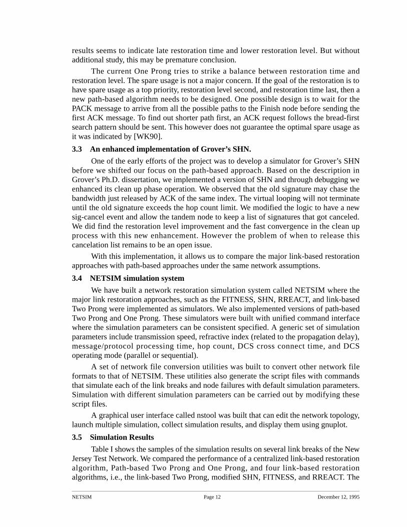
3.5 Simulation Results
Table I shows the samples of the simulation results on several link breaks of the NewJersey Test Network. We compared the performance of a centralized link-based restorationalgorithm, Path-based Two Prong and One Prong, and four link-based restorationalgorithms, i.e., the link-based Two Prong, modified SHN, FITNESS, and RREACT. The
NETSIM Page 13 December 12, 1995
simulation parameters are 8 kbps transmission speed, 1.4 refraction index, 10 msecprotocol processing time, 10 msec DCS cross connect time with the sequential operatingmode.
Restoration Time: centralized methods faster, link-based Two prong close.
Number of Messages: centralized methods have 8-10 times fewer messages.
Among the 23 link breaks of New Jersey test network, path based One Prong fullyrestored all 22 link breaks except N01-N02 break. This indicates there is still room for it tobe improved. Compared with fast link-based Two Prong, in worst case, path-based TwoProng and One Prong are about 8~9 times slower. The big message volume on themodified SHN is due to the large number of spares on the New Jersey test network. Thequeueing delay slows down the time performance of the modified SHN.
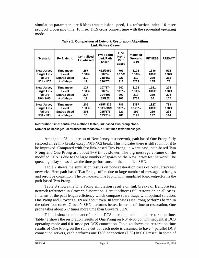
Table 2 shows the simulation results on node restoration cases of New Jersey testnetworks. Here path-based Two Prong suffers due to large number of message exchangesand resource contention. The path-based One Prong with simplified logic outperforms thepath-based Two Prong.
Table 3 shows the One Prong simulation results on link breaks of Bellcore testnetwork referenced in Grover’s dissertation. Here it achieves full restoration on all cases.In terms of the path length efficiency which compare spare usage with optimal solution,One Prong and Grover’s SHN are about even. In four cases One Prong performs better. Inthe other four cases, Grover’s SHN performs better. In terms of time to restoration, Oneprong takes about 5~7 times more time than Grover’s SHN.
Table 4 shows the impact of parallel DCS operating mode on the restoration time.Table 4a shows the restoration results of One Prong on N04-N03 cut with sequential DCSoperating mode and 0.01msec per DCS connection. Table 4b shows the restoration timeresults of One Prong on the same cut but each node is assumed to have 4 parallel DCSconnection servers, each performs one DCS connection (DS3) in 0.01 msec. In some of
Table 1: Comparison of Network Restoration AlgorithmsLink Failure Cases
Scenario Perf. MetricCentralizedLink-based
Two ProngLink/Path
based
OneProngPath
Based
modified Grover’s
SHNFITNESS RREACT
New JerseySingle Link
FailureN01 - N02
Time msec Level
Spares Used# of Msgs
257100%31212
482/2959100%
318/160126/674
79390.5%
226313
3126100%312
4269
1646100%339185
592100%31278
New JerseySingle Link
FailureN04- N05
Time msecLevel
Spares Used# of Msgs
127100%23712
107/874100%
204/19689/222
940100%209106
3173100%212
2753
1151100%26930
275100%204107
New JerseySingle Link
FailureN08 - N11
Time msecLevel
Spares Used# of Msgs
205100%30113
475/4836100%/98%
215/175133/914
786100%221266
238793.75%
1923177
1827100%239197
739100%233114
NETSIM Page 14 December 12, 1995
the link breaks, the last restoration path only have one bandwidth and the parallel DCSdoes not help the shorten the time to restoration number. It does shorten the restorationtime those restoration paths with multiple bandwidth.
* These are the simulation results of our implementation of Fujitsu’s KOMINE network restoration algorithm.
Table 2: Comparison of Network Restoration Algorithms Node Failure Cases
Scenario Perf. MetricCentralized
Pathbased
CentralizedLink
based
CentralizedCombined
Komine*Two ProngPath based
OneProngPath
Based
New JerseySingle Node
FailureN04
Time msecLevel
# of MsgsSpare Usage
191100%
33-
153100%
28-
167100%
11-
2025100%1647
-
3175100%596
61(r61)
466100%209
63(r61)
New JerseySingle Node
FailureN05
Time msecLevel
# of MsgsSpare Usage
416100%
18-
37090. 5%
18-
426100%
18-
233791%1633
-
1895469%5246
72(r102)
107778.38%
47861(r102)
Table 3. One Prong restorat ion resu lts on bellcore.net [Grover ’89]with 8kbps, dxct=0.01ms, ppt=0.01ms========================================N01-N00 p=18/5/0/13 bw=5/18= 27.78% @0.730550 m=1115 s=0/10/10, N=5/5, L=10/10N02-N01 p=13/5/0/8 bw=5/13= 38.46% @0.796250 m=847 s=0/10/10, N=5/5, L=10/10N02-N00 p=18/7/0/11 bw=7/18= 38.89% @2.586373 m=2337 s=0/14/14, N=7/7, L=14/14N03-N00 p=18/11/0/7 bw=11/18= 61.11% @2.203324 m=949 s=0/35/35, N=11/11, L=31/35*N04-N00 p=13/13/0/0 bw=13/13=100.00% @2.387124 m=674 s=0/29/29, N=13/13, L=29/29N04-N02 p=4/4/0/0 bw=4/4=100.00% @0.820675 m=224 s=0/8/8, N=4/4, L=8/8N04-N03 p=17/17/0/0 bw=17/17=100.00% @2.013275 m=785 s=0/37/37, N=17/17, L=36/37+N05-N00 p=14/11/0/3 bw=11/14= 78.57% @1.738950 m=1017 s=0/29/29, N=11/11, L=28/29*N05-N04 p=12/8/0/4 bw=8/12= 66.67% @2.480748 m=702 s=0/16/16, N=8/8, L=16/16N06-N04 p=4/3/0/1 bw=3/4= 75.00% @0.374275 m=402 s=0/6/6, N=3/3, L=6/6N07-N00 p=13/13/0/0 bw=13/13=100.00% @2.440523 m=663 s=0/26/26, N=13/13, L=26/26+N07-N05 p=12/11/0/1 bw=11/12= 91.67% @2.332974 m=736 s=0/31/31, N=11/11, L=27/31N07-N04 p=20/20/0/0 bw=20/20=100.00% @2.138399 m=892 s=0/53/53, N=20/20, L=40/53*N07-N06 p=10/2/0/8 bw=2/10= 20.00% @1.250725 m=602 s=0/4/4, N=2/2, L=4/4N07-N03 p=15/15/0/0 bw=15/15=100.00% @2.692998 m=837 s=0/36/36, N=15/15, L=34/36+N08-N04 p=12/12/0/0 bw=12/12=100.00% @1.300680 m=528 s=0/24/24, N=12/12, L=24/24N08-N03 p=13/13/0/0 bw=13/13=100.00% @2.223129 m=757 s=0/34/34, N=13/13, L=34/34N08-N07 p=14/14/0/0 bw=14/14=100.00% @1.780604 m=702 s=0/29/29, N=14/14, L=28/29*N09-N08 p=20/2/0/18 bw=2/20= 10.00% @0.814250 m=3503 s=0/4/4, N=2/2, L=4/4N10-N04 p=12/12/0/0 bw=12/12=100.00% @1.180575 m=540 s=0/24/24, N=12/12, L=24/24N10-N07 p=16/16/0/0 bw=16/16=100.00% @1.929555 m=822 s=0/39/39, N=16/16, L=37/39+N10-N08 p=16/16/0/0 bw=16/16=100.00% @2.127549 m=891 s=0/33/33, N=16/16, L=33/33N10-N09 p=9/7/0/2 bw=7/9= 77.78% @0.986239 m=830 s=0/14/14, N=7/7, L=14/14
Here the path network efficiency and path length efficiency are represented by the numbers after “N=” and “L=”
The optimal spare usages are generated by a front end interface to Bertsekas and Tseng’s relax-III code.
NE
TS
IMP
age 15
De
cembe
r 12, 1995
Figure 4. nstool
NETSIM Page 16 December 12, 1995
0
20
40
60
80
100
0 50 100 150 200 250 300 350 400 450
Restoration
Time (msec)
Network Restoration Performance Plot
TWOPRONG_QD0''TWOPRONG_QD500''
TWOPRONG_QD1000''TWOPRONG_QD5000''
TWOPRONG_QD10000''
Generated by GNUPLOT
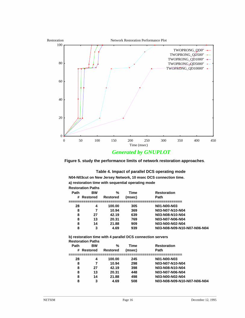
Figure 5. study the performance limits of network restoration approaches .
Table 4. Impact of parallel DCS operating modeN04-N03cut on New Jersey Network, 10 msec DCS connection time.a) restoration time with sequential operating modeRestoration Paths
Path BW % Time Restoration # Restored Restored (msec) Path====================================================== 28 4 100.00 305 N01-N00-N03 8 7 10.94 369 N03-N07-N10-N04 8 27 42.19 639 N03-N08-N10-N04 8 13 20.31 769 N03-N07-N06-N04 8 14 21.88 909 N03-N00-N02-N04 8 3 4.69 939 N03-N08-N09-N10-N07-N06-N04
b) restoration time with 4 parallel DCS connection servers Restoration Paths
Path BW % Time Restoration # Restored Restored (msec) Path====================================================== 28 4 100.00 245 N01-N00-N03 8 7 10.94 298 N03-N07-N10-N04 8 27 42.19 398 N03-N08-N10-N04 8 13 20.31 448 N03-N07-N06-N04 8 14 21.88 498 N03-N00-N02-N04 8 3 4.69 508 N03-N08-N09-N10-N07-N06-N04
NETSIM Page 17 December 12, 1995
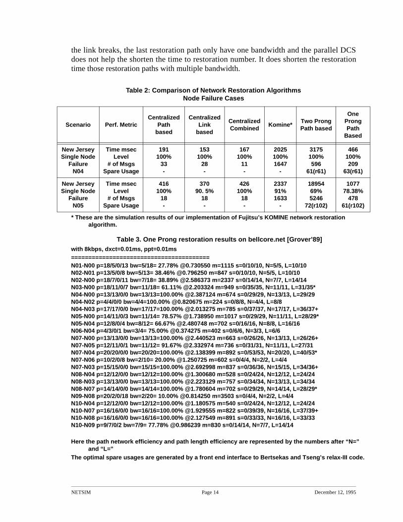
Figure 4 shows the screendump of nstool with its canvas window display New Jersey testnetwork and an output message window showing part of the simulation results. The simulationparameter specification frame allows a user to select one or several network restoration algorithmsto be launched in one simulation run. It also allows the user to specify the network parameters tobe specified. For the link distances between nodes, it provides option to use the link distance fieldin the network file or calculate the distance based on the coordinates of the two end nodes.NETSIM allows uses to specify the location of nodes based on the V&H coordinates or thelongitude/latitude system.
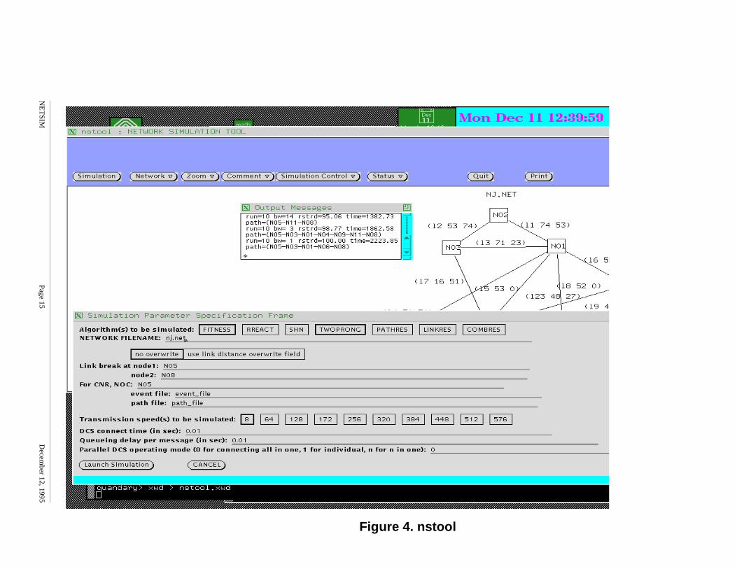
Figure 5 shows the plotting feature of nstool. After nstool launched the simulation, itcollects the simulation results which are returned via a Berkeley socket, generates the gnuplotcommands and data files, and execute the gnuplot to display the simulation results. This facilitatesthe user to analyze the effect of changing certain network parameters. Figure 5 shows the impactof changing the message processing time from 10 msec to 0 msec on the performance of TwoProng over a specific link cut. It shows that changing the message processing time from 10 msecto 1 msec, the restoration time dramatically reduces from 430 msec to 100 msec. After that, othernetwork parameter such as the transmission speed becomes the dominating factor.
4. EvaluationThe success of the proposed project can be assessed by the performance of the network
survival algorithms generated by this project, and by the usefulness of NETSIM and the analysisreport on the comparison of various network survival approaches. The performance of theproposed network survival algorithms and their comparison with the existing algorithms can bedemonstrated by using NETSIM. Based on the results we discussed in Section 3, the project isquite successful since we now have a tool to compare the link-based network restoration with thepath-based network restoration under the same network parameter assumptions. The NETSIMwill allow network designers/planners to check the reliability of a network topology/status interms of the restoration level and restoration time. The front end interface to the relax-III code canserve as a tool for planning the spare capacity in the network.
US West will provide feedbacks on the NETSIM usage in their research and networkmanagement organizations, and on the usefulness of the analysis report. Those feedbacks willfurther indicate the degree of success of the project.
5. Intellectual property developed under sponsorship of this grant.We have designed path-based Two Prong and One Prong network restoration approach. The
NETSIM software can be licensed to companies in telecommunication industry that operate orplan networks. To obtain the source code or the object code of NETSIM system, send email [email protected]. A copy of the final report will be sent to the Larry Anderson, who isour campus Technology Transfer officer.
6. Technology Transfer section that describes the technology exchange going in both direction between UCCS and the Collaborating Company.
We have given presentations of our research results to researchers at US West AdvancedTechnologies twice and got valuable feedbacks from them. From them, we know how the V&HCoordinate system works. Their feedbacks encouraged us to focus on the One Prong development
NETSIM Page 18 December 12, 1995
in the second half of the project, since it can be used both in the network restoration and inthe network provisioning. Based on the feedback, we have focused on improving therestoration level. We have achieved significant improvement on the restoration level, whilemaintaining, or in some cases improving the restoration time. We have delivered theNETSIM manual and software to US West Advanced Technologies.
AcknowledgmentWe would like to thank Dr. Dimitri Bertsekas for showing us how to use their
efficient relax-III code. We would like to thank Dr. George I. Bell and Dr. Steve Chiu fortheir feedback and suggestions on the project. This work can not complete with thecontributions from the following graduate students: Ron Gray’s work on the Gnuplotinterface, Mark Bracco and Al Backmann’s work on the front end interface to relax-III,John Bicknell’s work on link-based Two Prong and early version of path-based TwoProng.
References [Bert88] D. P. Bertsekas and P. Tseng, “Relaxation Methods for Minimum Cost Ordi-
nary and Centralized Network Flow Problems,” Operations Research Jour-nal, Vol. 36, 1988, pp. 93-114.
[Chow93a] C.-H. E. Chow, J. Bicknell, S. McCaughey, and S. Syed, “A Fast DistributedNetwork Restoration Algorithm,” Proceedings of 12th International Phoe-nix Conference on Computers and Communications, March 24-26, 1993,Scottsdale, Arizona.
[Chow93b] C.-H. E. Chow, S. McCaughey, and S. Syed, “RREACT: A Distributed Pro-tocol for Rapid Restoration of Active Communication Trunks,” Proceed-ings of 2nd IEEE Network Management and Control Workshop, Sept. 21-23, 1993.
[Chow93c] C.-H. E. Chow, J. Bicknell, and S. Syed, “Performance Analysis of FastLink Restoration Algorithms,” accepted to be published in 1994 on Journalof Digital and Analog Communication Systems. Part of the research resultspublished in Proceedings of Globecom 93.
[Chow93d] C.-H. E. Chow, V. Narasimhan, and S. Syed, “Analysis of Centralized Net-work Restoration,” Proceedings of 2nd International Conference on Com-puter Communications and Networks, June 28-30, 1993, San Diego.
[Grov89] W. D. Grover, “SELFHEALING NETWORKS: A Distributed Algorithmfor k-shortest link-disjoint paths in a multi-graph with applications in realtime network restoration”, in Doctoral Dissertation for the Department ofElectrical Engineering, University of Alberta, Fall 1989.
[WK90] J. S. Whalen and J. Kenney, “Finding maximal link disjoint paths in a multi-graph,” in Proceedings of GlobalCom ‘90, (San Diego), pp. 403.6.1–403.6.5, Dec. 1990.
[Wrob90] Wrobel, L. A., “Disaster Recovery Planning for Telecommunication,”Artech House, Inc., Norwood, MA, 1990.
[Wu92] Wu, T. H., “Fiber Network Service Survivability,” Artech House, Inc., Nor-wood, MA, 1992.

NETSIM Page 19 December 12, 1995
[Yang88] Yang, C. H. and S. Hasegawa, “FITNESS: Failure Immunization Technolo-gy for Network Service Survivability,” Proc. of GlobalCom ‘88, pp. 47.3.1-47.3.6, November 1988.