Embed Size (px)
Citation preview
1
Quality Systems Group
The Quality Systems Group Final Report and Recommendations to the 29th
ITTC
2
Quality Systems Group
1. GENERAL
1.1 Membership and Meetings Benedetti, Lanfranco, CNR-INM (Secretary) Chen, Weimin, SSSRI Derradji-Aouat ,Ahmed, NRCC Ferrando, Marco, Genova Univ. (Chair) Grigoropoulos, Gregory, NTUA Kitazawa, Daisuke, Tokyo University Park, Joel, NSWCCD Reed, Arthur M., NSWCCD Sena Sales, Joel Jr., UFRJ Valle, Jesus, CEHIPAR
As of August 8th 2019, Ahmed Derradji-Aouat Joined the Quality Systems Group
On September 1st 2020, Jesus Valle left the Quality Systems Group
The Group held four meetings as follows: September 22nd 2017, Wuxi, June 25th to 26th 2018, Madrid September 2nd to 3rd 2019, Athens February 20th to 21st 2020, Rome
From here on, in order to save space in the report, the Quality Systems Group will be ad-dressed as QSG.
1.2 Terms of Reference given by the 29th ITTC to the QSG.
1. Update all ITTC Recommended Proce-dures and Guidelines to conform to the re-quirements of Recommended Procedure 4.2.3-01-03, Work Instruction for Format-ting ITTC Recommended Procedures and Guidelines.
2. Support the Technical Committees in their work on Recommended Procedures. Sup-ply the chairmen of the new committees with the MS Word versions of the relevant procedures.
3. Maintain the Manual of ITTC Recom-mended Procedures and Guidelines. Co-
ordinate the modification and re-editing of the existing procedures according to the comments made by ITTC member organi-zations at the Conference and by the Tech-nical Committees.
4. Observe the development or revision of ISO Standards regarding Quality Control.
5. Update the ITTC Symbols and Terminol-ogy List.
6. Update the ITTC Dictionary of Hydrome-chanics.
7. Revise and update the existing ITTC Rec-ommended Procedures according to the comments of Advisory Council, Technical Committees and the Conference.
8. After the third AC Meeting, review and edit new ITTC Recommended Procedures with regard to formal Quality System re-quirements including format and compli-ance of the symbols with the ITTC Sym-bols and Terminology List.
9. Support the Technical Committees with guidance on development, revision and update of uncertainty analysis procedures.
10. Observe ISO standards for uncertainty analysis, in particular the uncertainty anal-ysis terminology.
11. Review developments in metrology theory and uncertainty analysis and issue appro-priate Procedures.
12. Continue to maintain the online Wiki keeping it up to date and in line with the adopted documents of the ITTC.
13. At the beginning of the period, organize an electronic repository of information and data on the benchmarks cases. ITTC mem-ber organizations should then be invited to participate in the adoption of the bench-mark and contribute to the data-base.
2. TASKS PERFORMED
2.1 Update all ITTC Recommended Proce-dures and Guidelines to conform to the requirements of Recommended Proce-dure 4.2.3-01-03, Work Instruction for
3
Quality Systems Group
Formatting ITTC Recommended Pro-cedures and Guidelines.
This task was performed during the 28th ITTC. Its insertion into the 29th QSG ToR is probably due to a “Cut and Paste” error in draft-ing 29th ITTC QSG ToR
2.2 Support the Technical Committees in their work on Recommended Proce-dures. Supply the chairmen of the new committees with the MS Word ver-sions of the relevant procedures.
A total of 58 MS Word files containing the procedures to be updated, together with the tem-plate to be used for drafting new procedures was sent to the Chairmen of the various ITTC Com-mittees.
QSG cooperated with 29th Conference Chairman to produce the template for Commit-tee report to be distributed for the next Confer-ence
2.3 Maintain the Manual of ITTC Recom-mended Procedures and Guidelines. Co-ordinate the modification and re-editing of the existing procedures ac-cording to the comments made by ITTC member organizations at the Conference and by the Technical Com-mittees.
The revision of the Manual of ITTC Recom-mended Procedures and Guidelines included 84 documents:
• 9 existing procedures were deleted • 13 new Procedures/Guidelines have been
approved • 62 existing procedures have been reviewed
or updated. • 125 disclaimers have been inserted in ITTC
recommended Procedures and Guidelines as per Executive Committee request
• 82 equations in Recommended Procedures and Guidelines have been translated from
the old MathType format to the MS Word equation editor format.
During the activity connected with this ToR the QSG realized that a number of procedures need further revision; especially when dealing with UA. Some procedures require extensive updates to conform to BIPM (2008) GUM. Some procedures still refer to the ISO GUM.
A proposal for future work has been added to this effect.
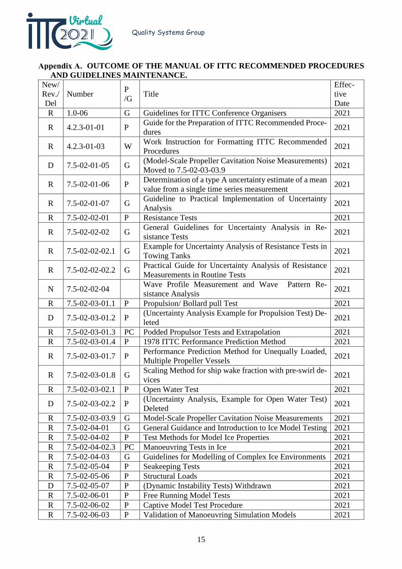
The table of “revision outcomes” is illus-trated in Appendix A.
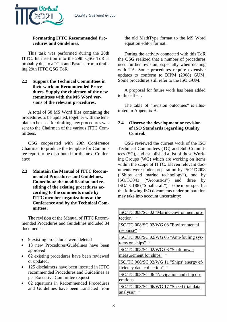
2.4 Observe the development or revision of ISO Standards regarding Quality Control.
QSG reviewed the current work of the ISO Technical Committees (TC) and Sub-Commit-tees (SC), and established a list of those Work-ing Groups (WG) which are working on items within the scope of ITTC. Eleven relevant doc-uments were under preparation by ISO/TC008 (“Ships and marine technology”), one by ISO/TC043 (“Acoustics”) and three by ISO/TC188 (“Small craft”). To be more specific, the following ISO documents under preparation may take into account uncertainty:
ISO/TC 008/SC 02 "Marine environment pro-tection" ISO/TC 008/SC 02/WG 03 "Environmental response" ISO/TC 008/SC 02/WG 05 "Anti-fouling sys-tems on ships" ISO/TC 008/SC 02/WG 08 "Shaft power measurement for ships" ISO/TC 008/SC 02/WG 11 "Ships’ energy ef-ficiency data collection" ISO/TC 008/SC 06 "Navigation and ship op-erations" ISO/TC 008/SC 06/WG 17 "Speed trial data analysis"
4
Quality Systems Group
ISO/TC 008/SC 08/WG 14 "Propeller" ISO/TC 008/SC 08/WG 20 "Antifouling paints" ISO/TC 008/SC 08/WG 23 "Buoyancy sup-port system" ISO/TC 008/SC 12 "Ships and marine tech-nology - Large yachts" ISO/TC 008/SC 12/WG 05 "Quality assess-ment and acceptance criteria" ISO/TC 008/SC 13 "Marine technology" ISO/TC 008/SC 13/WG 01 "Submersibles" ISO/TC 008/WG 09 "Polar (Arctic/Antarctic) regions"
There are another 66 ISO/WG working on Uncertainty Analysis on procedures not directly associated with ITTC scope of interest.
2.5 Update the ITTC Symbols and Termi-nology List.
As regards the Symbols & Terminology List QSG decided to start a systematic check to be sure that symbols used in the standing proce-dures are contained in the S&T List.
The documents belonging to the following sections of the Register have been checked for symbol usage:
• 7.5-02-01 • 7.5-02-02 • 7.5-02-03 • 7.5-02-04 • 7.5-02-05 • 7.5-02-06 • 7.5.02-07-01 • 7.5-02-07-03
A total of 70 documents have been checked. The result of the check has been disappointing, since many documents make use of symbols not included into the Symbols and Terminology list or of incorrect symbols with respect to those in-cluded in the List.
The observations regarding symbols have been sent to the relevant committees requesting action to rectify this situation.
Changes made to the Symbols & Terminol-ogy List are as follows:
• The definition of CDA has been updated fol-lowing an AC suggestion.
• Hw1/3, Hw1/3d, Hw1/3u need to be checked against the procedures and eventually de-leted as non-necessary symbols. The new symbols will be: Hw1/3, H1/3w (for waves) and H1/3s (swells), in procedure 7.5-04-01-01.1.
• The left-hand coordinate axes system has been removed from the Symbols and Termi-nology List.
• Several other symbols have been added, in-cluding: Linear momentum (P) and Angular momentum (L).
• A number of new symbols have been added according to a Resistance and Propulsion Committee proposal.
2.6 Update the ITTC Dictionary of Hy-dro-mechanics.
A new section has been developed and added to the ITTC Dictionary of Hydrodynamics, it is: Offshore Engineering. This initial version of the new section has focused on offshore oil and gas production, all from the perspective of hydrody-namics—those platforms, vessels and compo-nents for which model testing and/or perfor-mance related calculations would be performed. Those components for which no hydrodynamic issues or requirements would be expected (e.g., blowout preventers) are not included, which is not to say that these components are not critical parts of the entire system.
The Offshore Engineering additions start with a definition of offshore platforms, in gen-eral and specifically those related to oil and gas drilling and production. It then contains defini-tions and descriptions of various types of drill-ing platforms, fixed and mobile (Fixed Plat-forms, Compliant Towers, Jack-up rigs, Mobile
5
Quality Systems Group
Offshore Drilling Units, (MODUS), Semi-sub-mersible drilling units, Drill ships and Ultradeep water drilling units). It then presents the various systems used for production (Gravity-based structure (GBS); Tension Leg Platform—Con-ventional, New Generation; Semisubmersible floating production units (semi-FPU); Spar Plat-forms—Classic, Truss, Cell, Mini-Doc; Float-ing production systems (FPS); Floating, produc-tion, storage and offloading (FPSO) vessels—Shipshape, circular; and Floating liquefied nat-ural gas (FLNG) vessels), and specialty vessels, particularly Anchor Handler Vessels (AHV) and Anchor Handling Tug Supply Vessels (AHTS). Illustrations or photographs are provided for many of many of the above platforms and ves-sels.
The contributions to the new section end with specific components involved in offshore platforms and some of the performance issues that they may experience. The particular com-ponents included are: Risers, Strakes, Bottom Templates or Guides, and Mooring systems. The particular issues particular to offshore plat-forms are Vortex induced vibration (VIV) and Vortex Induced motion (VIM).
2.7 Revise and update the existing ITTC Recommended Procedures according to the comments of Advisory Council, Technical Committees and the Confer-ence.
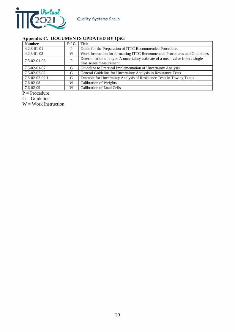
The QSG updated 8 documents, as listed in Appendix C.
The following 11 documents were reviewed:
• 4.2.3-01-01 — Guide for the Preparation of ITTC Recommended Procedures
• 4.2.3-01-03 — Work Instruction for format-ting ITTC Recommended Procedures and Guidelines
• 7.5-02-01-06 — Determination of a type A uncertainty estimate of a mean value from a single time series measurement
• 7.5-02-01-07 — Guideline to Practical Im-plementation of Uncertainty Analysis
• 7.5-02-02-02 — General Guidelines for Un-certainty Analysis in Resistance Tests
• 7.5-02-02-02.1 — Example for Uncertainty Analysis of Resistance Tests in Towing Tanks
• 7.5-02-05-05 — Evaluation and Documen-tation of HSMV
• 7.5-02-06-04 — Uncertainty Analysis for Manoeuvring Predictions based on Captive Manoeuvring Tests
• 7.5-02-06-05 — Uncertainty Analysis for Free Running Model Tests
• 7.6-02-01 — Calibration of a Steel Ruler • 7.6-02-08 — Calibration of Weights • 7.6-02-09 — Calibration of Load Cells
As regards the outcome of the review:
4.2.3-01-01: this procedure did not contain a reference section and consequently has been up-dated.
4.2.3-01-03: this work instruction has been updated to correct minor errors and inconsisten-cies.
7.5-02-01-06: the first version of the docu-ment only included the equations for analog computations and the purposes of this revision was to include the equations for digital data pro-cessing. Martin van Rijsbergen, one of the orig-inal authors agreed to participate to the revision process. This procedure has been updated and includes the most recent recommendations of the Manoeuvring Committee.
7.5-02-01-07: Equations (9) and (12) have been corrected; data were correct in tables; a Central finite difference form was added as Equation (4); the Reference list has been up-dated
7.5-02-02-02: this guideline has been re-viewed for consistency with guideline 7.5-02-02-02.1 and updated. Significant revisions have been made, and some editorial changes by the Resistance and Propulsion Committee were in-cluded. The following sections were added:
6
Quality Systems Group
• Outlier and non-linear detection methods • Force computation from mass loading for
dynamometers in a calibration fixture • Distinction between methods for confidence
and prediction limits with relevant equations • Running sinkage and trim • List of symbols was added. A running sink-
age and trim section was added.
7.5-02-02-02.1: The guideline has been re-viewed for consistency with guideline 7.5-02-02-02 and updated. The main changes are as fol-lows:
• Force reported in Newton (N) rather than kilogram force (kgf)
• Uncertainty estimates in expanded uncer-tainty, U, rather than standard uncertainty, u.
• Sinkage and trim data processing equations with uncertainty analysis
• Equations for confidence and prediction lim-its
• List of symbols • Reference list updated
For repeat tests, a distinction is made be-tween confidence limit and prediction limit. An uncertainty estimate for a series of tests is com-puted from the standard deviation of the mean value. The uncertainty estimate for total re-sistance, RT, is from the 95 % confidence limit
𝑈𝑈𝑅𝑅�T = 𝑘𝑘 𝑠𝑠𝑅𝑅T √𝑁𝑁⁄ (1)
where k is the coverage factor, s the computed standard deviation of N samples. For a small number of samples, the coverage factor k can be the Student-t distribution t0.025, N-1 at the 95 % confidence level. However, if the uncertainty is applied to some future event such as an uncer-tainty estimate for a single sample from a previ-ous estimate of the standard deviation or esti-mate at full-scale from model-scale, then the un-certainty from the prediction limit is
𝑈𝑈 = 𝑘𝑘𝑠𝑠�1 + 1 𝑁𝑁⁄ (2)
or for a large number of samples at the 95 % pre-diction limit U = 2s.
7.5-02-05-05: this procedure was updated regarding symbols usage. The revision number remains 02 and the date of approval 2014.
7.5-02-06-04: this procedure has been re-viewed by QSG as regards format issues. The updated document has been forwarded to the Manoeuvring Committee for further review.
7.5-02-06-05: this procedure has been re-viewed and updated by QSG as regards format issues. The updated document has been for-warded to the Manoeuvring Committee for fur-ther review.
7.6-02-01: After a long discussion QSG re-considered its proposal to review the document. Considering that UA procedures prescribe trace-ability to a National Metrology Laboratory, in-ternal calibration of steel rulers cannot be used anymore. To this effect, QSG proposed to delete the document. That proposal has been rejected by the AC, which asked QSG to prepare a pro-cedure on the internal calibration of steel rulers or a practical way to check length measurement devices in towing tanks.
QSG did not manage to produce this docu-ment in time and this task has been inserted into the Recommendations for Future Work
7.6-02-08: This working instruction has been updated with modifications for consistency with other documents. The minimum tolerance for weights was changed to OIML Class M2.
7.6-02-09: This working instruction has been greatly simplified. A calibration example is included that compares random to sequential loading of weights on a calibration stand. The following equation is included for the conver-sion of mass in kg to force in N.
𝐹𝐹 = 𝑚𝑚𝑚𝑚(1 − 𝜌𝜌A 𝜌𝜌M)⁄ (3)
where m is the mass in kg, 𝑚𝑚 is local accelera-tion of gravity in m/s2, ρA is air density, and ρM
7
Quality Systems Group
is the density of the weight in kg/m3. The nomi-nal values for Equation (3) are as follows:
𝑚𝑚 9.80665 m/s2 for standard gravity ρA 1.2 kg/m3 ρM 8000 kg/m3
Local gravity is typically less than standard gravity. The last term in Equation (3) is an air buoyancy correction from Archimedes principle and is typically 0.017 %. The mass in Equation (3) is the sum of the weights added to the cali-bration stand.
𝑚𝑚 = ∑ 𝑚𝑚𝑖𝑖𝑛𝑛𝑖𝑖=1 (4)
If the tolerance of the weights is applied as the uncertainty estimate, the uncertainty is the tolerance of the total mass, m.
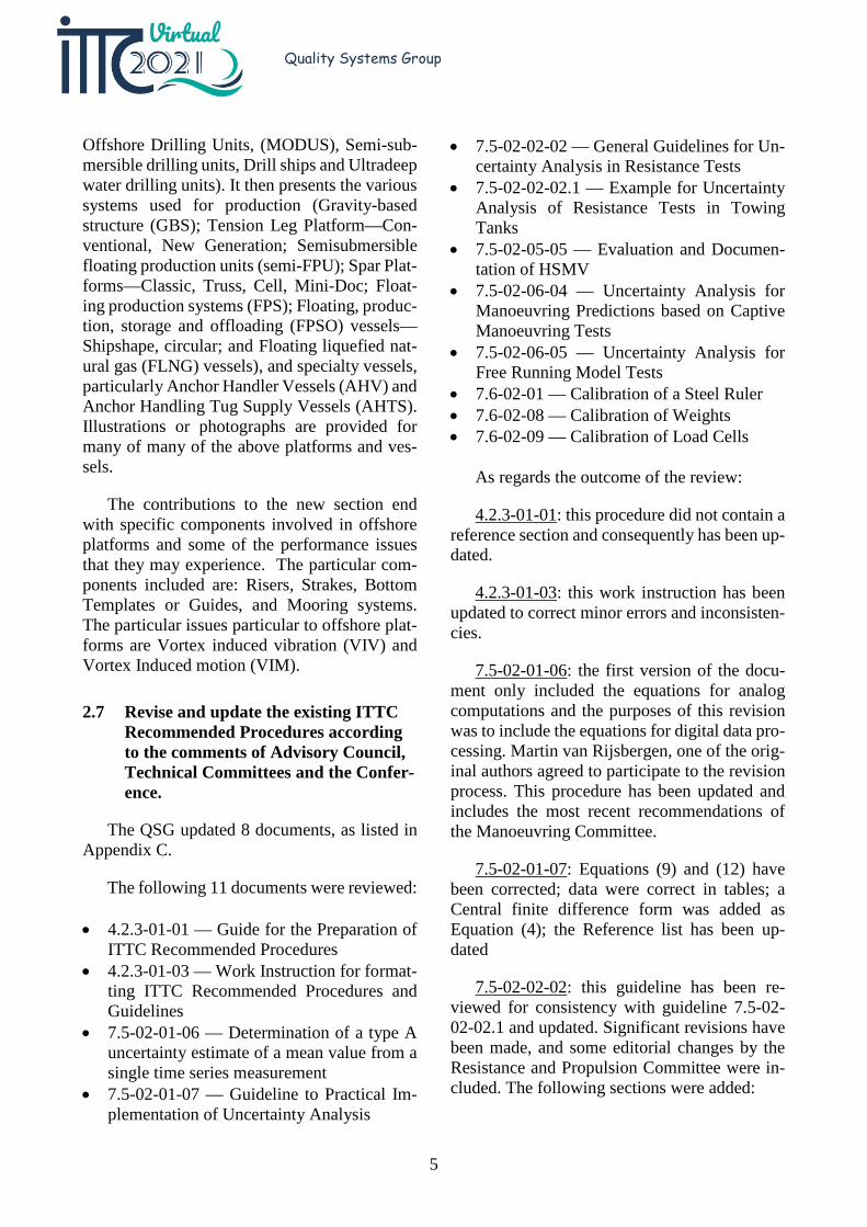
The procedure also includes an example for the comparison of sequential loading to random loading. An example of the loading is given in Figure 1.
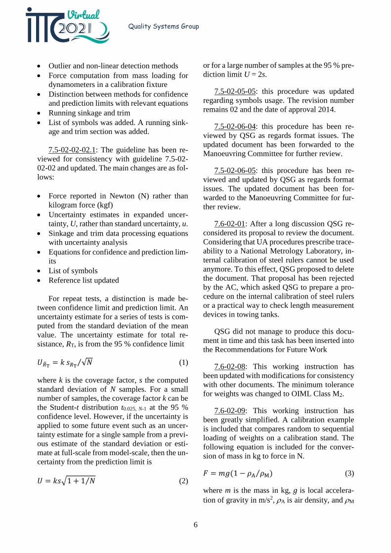
The calibration result is presented in Fig-ure 2 as a residual plot. By a hypothesis test, the calibration constants are statistically the same for the two methods, but the uncertainty is sig-nificantly less by the random method.
2.8 After the third AC Meeting, review and edit new ITTC Recommended Procedures with regard to formal Quality System requirements includ-ing format and compliance of the sym-bols with the ITTC Symbols and Ter-minology List.
The QSG review process regarded 56 exist-ing and 13 new procedures adding to a total of 69 documents, as illustrated in Appendix B.
The document 0.0 Register has been updated accordingly.
A template in word format has been pre-pared to write new procedures during the next ITTC period. To write a new procedure, an au-thor will open the new file with the following
template: ProcTemplate.dotx. The file will be available on the ITTC Web site.
Figure 1. Loading sequence for Kempf & Remmers H48 dynamometer in thrust.
Figure 2. Calibration data for Kempf & Remmers H48 dynamometer in thrust.
2.9 Support the Technical Committees with guidance on the development, re-vision and update of uncertainty anal-ysis procedures.
QSG liaised with Stability in Waves com-mittee on the revision of procedures 7.5-02-07-04.3, 7.5-02-07-04.4, 7.5-02-07-04.5, their pro-posed change of formulation in ITTC Proce-dure 7.5-03-02-03, Practical Guidelines for ship CFD application, and the development of new ITTC Procedures: Inclining Tests, and Extrap-olation for direct assessment stability in waves
8
Quality Systems Group
7.5-02-01-06; Manoeuvring Committee sup-plied a revised version for QSG check
QSG assisted the Ocean Engineering Com-mittee on the uncertainty analysis of a bench-mark test.
2.10 Observe ISO standards for uncertainty analysis, in particular the uncertainty analysis terminology.
The responsibility for the ISO Guide to the Uncertainty in Measurement (GUM) is now the Bureau International des Poids et Mesures (BIPM). The focus in the future should be with BIPM not ISO. The Joint Committee for Guides in Metrology (JCGM) within BIPM is now tasked with the GUM. JCGM is divided into two working groups as follows:
• Working Group on the Expression of Uncer-tainty in Measurement (JCGM-WG1: GUM)
• Working Group on the International Vocab-ulary of Metrology (JCGM-WG2: VIM)
Each working group meets twice per year.
The following are the documents issued by WG1:
• JCGM 100:2008, “Evaluation of measure-ment data—Guide to the expression of un-certainty in measurement,” GUM 1995 with minor corrections
• JCGM 101:2008, “Evaluation of measure-ment data—Supplement 1 to the ‘Guide to the expression of uncertainty in measure-ment’—Propagation of distributions using a Monte Carlo method”
• JCGM 102:2011, “Evaluation of measure-ment data—Supplement 2 to the ‘Guide to the expression of uncertainty in measure-ment’—Extension to any number of output quantities”
• JCGM 103:2020, “Evaluation of measure-ment data—Concepts and basic principles,” in review
• JCGM 104:2009, “Evaluation of measure-ment data – An introduction to the ‘Guide to
the expression of uncertainty in measure-ment’ and related documents”
• JCGM 106:2012, “Evaluation of measure-ment data—The role of measurement uncer-tainty in conformity assessment”
The following will be developed in the fu-ture:
• JCGM 107, “Applications of the least-squares method”
• JCGM 108, “Bayesian methods” • JCGM 109, “Statistical Models and Data
Analysis for Inter-Laboratory Studies (with application to Key Comparisons)”
• JCGM 110, “Examples of uncertainty eval-uation”
A revision to the GUM was circulated at the end of 2014. After a rejection of the draft revi-sion, the effort is now focused on the develop-ment of the supplements to the GUM. The cur-rent version of the VIM is version 3: JCGM 200:2012, “International vocabulary of metrol-ogy—Basic and general concepts and associated terms (VIM).” WG2 anticipates publishing ver-sion 4 in the near future. The web page for JCGM is as follows: https://www.bipm.org/en/committees/jc/jcgm/ .
2.11 Review developments in metrology theory and uncertainty analysis and is-sue appropriate Procedures.
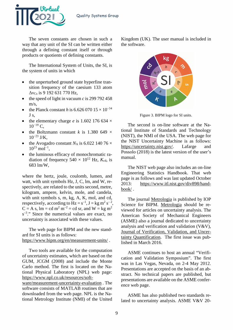
On 20 May 2019, a new International Sys-tem of Units (SI) was adopted. Details are de-scribed in Bureau International des Poids et Mesures (BIPM). The new logo for SI units is in Figure 3, which consists of seven constants, and the following definitions are from BIPM (2019).
“The definitions below specify the exact nu-merical value of each constant when its value is expressed in the corresponding SI unit. By fix-ing the exact numerical value the unit becomes defined, since the product of the numerical value and the unit has to equal the value of the constant, which is postulated to be invariant.
9
Quality Systems Group
The seven constants are chosen in such a way that any unit of the SI can be written either through a defining constant itself or through products or quotients of defining constants.
The International System of Units, the SI, is the system of units in which
• the unperturbed ground state hyperfine tran-sition frequency of the caesium 133 atom ΔνCs is 9 192 631 770 Hz,
• the speed of light in vacuum c is 299 792 458 m/s,
• the Planck constant h is 6.626 070 15 × 10−34 J s,
• the elementary charge e is 1.602 176 634 × 10−19 C,
• the Boltzmann constant k is 1.380 649 × 10−23 J/K,
• the Avogadro constant NA is 6.022 140 76 × 1023 mol−1,
• the luminous efficacy of monochromatic ra-diation of frequency 540 × 1012 Hz, Kcd, is 683 lm/W,
where the hertz, joule, coulomb, lumen, and watt, with unit symbols Hz, J, C, lm, and W, re-spectively, are related to the units second, metre, kilogram, ampere, kelvin, mole, and candela, with unit symbols s, m, kg, A, K, mol, and cd, respectively, according to Hz = s–1, J = kg m2 s– 2, C = A s, lm = cd m2 m–2 = cd sr, and W = kg m2 s–3.” Since the numerical values are exact, no uncertainty is associated with these values.
The web page for BIPM and the new stand-ard for SI units is as follows: https://www.bipm.org/en/measurement-units/ .
Two tools are available for the computation of uncertainty estimates, which are based on the GUM, JCGM (2008) and include the Monte Carlo method. The first is located on the Na-tional Physical Laboratory (NPL) web page: https://www.npl.co.uk/resources/soft-ware/measurement-uncertainty-evaluation . The software consists of MATLAB routines that are downloaded from the web page. NPL is the Na-tional Metrology Institute (NMI) of the United
Kingdom (UK). The user manual is included in the software.
Figure 3. BIPM logo for SI units.
The second is on-line software at the Na-tional Institute of Standards and Technology (NIST), the NMI of the USA. The web page for the NIST Uncertainty Machine is as follows: https://uncertainty.nist.gov/. Lafarge and Possolo (2018) is the latest version of the user’s manual.
The NIST web page also includes an on-line Engineering Statistics Handbook. That web page is as follows and was last updated October 2013: https://www.itl.nist.gov/div898/hand-book/ .
The journal Metrologia is published by IOP Science for BIPM. Metrologia should be re-viewed for articles on uncertainty analysis. The American Society of Mechanical Engineers (ASME) also a journal dedicated to uncertainty analysis and verification and validation (V&V), Journal of Verification, Validation, and Uncer-tainty Quantification. The first issue was pub-lished in March 2016.
ASME continues to host an annual “Verifi-cation and Validation Symposium”. The first was in Las Vegas, Nevada, on 2-4 May 2012. Presentations are accepted on the basis of an ab-stract. No technical papers are published, but presentations are available on the ASME confer-ence web page.
ASME has also published two standards re-lated to uncertainty analysis. ASME V&V 20-
10
Quality Systems Group
2009 is one of the more detailed documents on the application of V&V to computational fluid dynamics (CFD). ASME PTC 19.1-2018 is on test uncertainty and is compatible with the GUM, JCGM (2008).
A value of the local acceleration of gravity is necessary for the calculation of force in a cali-bration stand from mass per Equation (3). Previ-ously, a global tool was available for the com-putation of local gravity at the Physikalisch-Technische Bundesanstalt (PTB), Braunsch-weig, Germany, but that on-line calculation tool is no longer available. PTB provides a link an-other calculation tool, but it is applicable only to locations within Germany. That calculation tool is located at Bundesamt für Kartographie und Geodäsie (BKG) in Frankfurt, Germany, on the following web page: http://gibs.bkg.bund.de/geoid/gscomp.php?p=s. The input parameters are latitude and longitude in degrees and elevation in metres.
The USA has a similar web page at the Na-tional Geodetic Survey (NGS) as follows: https://geodesy.noaa.gov/cgi-bin/grav_pdx.prl. The default elevation for NSWCCD in that tool is 78.95 m. Another tool, which provides the el-evation from the latitude and longitude, yields an elevation of 40 m, and different value in local gravity is obtained. The NGS tool also provides an uncertainty estimate. Elevation is determined from the address in the following web page globally: https://elevation.maplogs.com/. When a laboratory is located on the GPS map, the lati-tude and longitude may be adjusted for a loca-tion within the facility.
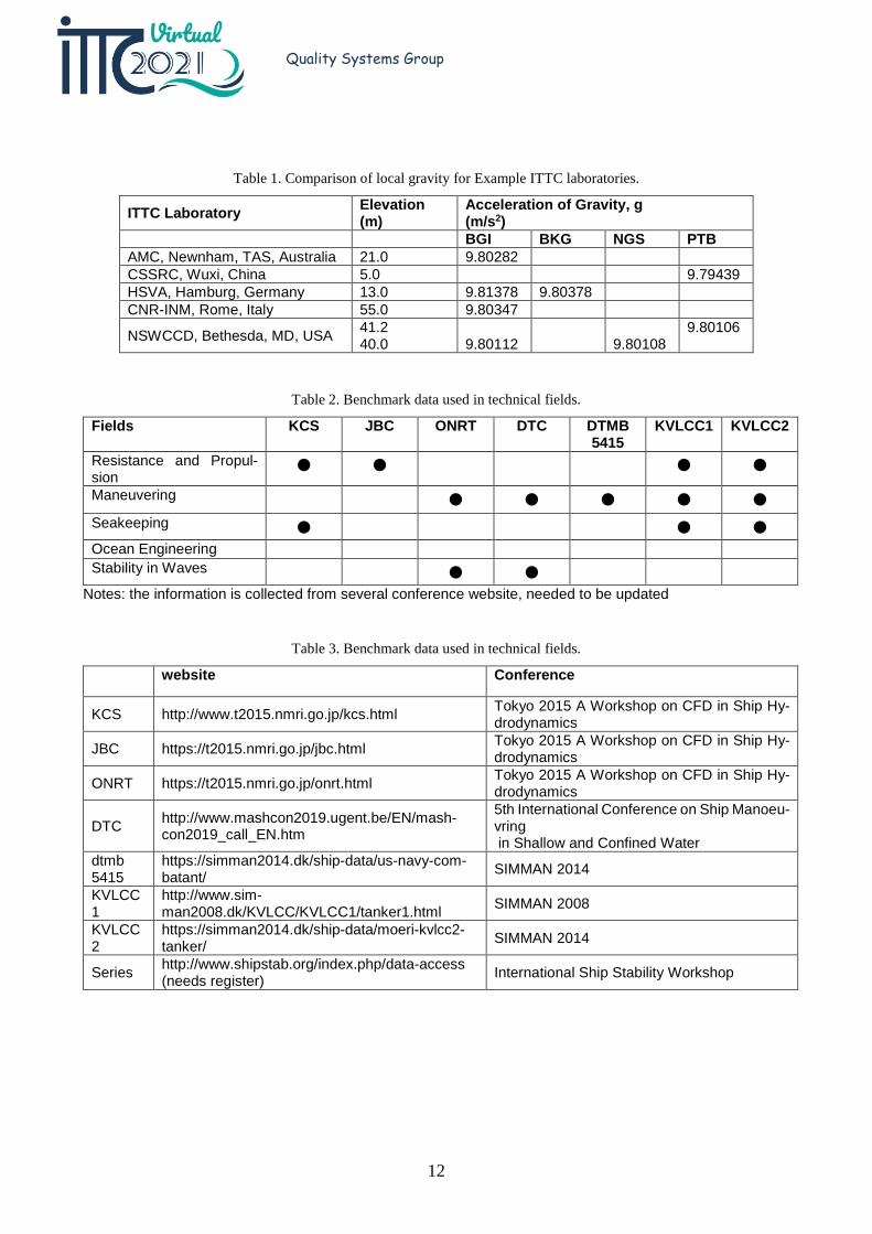
Another tool, which appears to provide in-ternational data, is at the Bureau Gravimétrique International (BGI), Toulouse, France. That web page is as follows: http://bgi.obs-mip.fr/data-products/outils/pre-diction-of-gravity-value/ . It does not provide data for CSSRC. A comparison of the values of local gravity, g, is summarized in Table 1 for ex-ample ITTC laboratories by the different tools. The PTB values in the table are from ITTC (2017), Table 1.
As a final note, the QSG observes that the ITTC focuses on uncertainty, while neglecting the incorporation of confidence bands in the re-sults from committees dealing with stochastic processes. The size of the confidence bands will in general be significantly larger than the uncer-tainty bounds. And half or more (if the Manoeu-vring Committee is dealing with manoeuvring in waves) of the General Committees are working with stochastic processes.
2.12 Continue to maintain the online Wiki keeping it up to date and in line with the adopted documents of the ITTC.
In ITTC (2011), when the ITTC-wiki was established, some positive feedbacks visits and returning visitors were counted, as time has passed, the level of feedback has been continu-ously decreasing. The thrust of the wiki tool has been to build, refine and review concepts and notions around the definitions contained in the Dictionary of Hydromechanics through collec-tive knowledge. However, because the content of the Dictionary of Hydromechanics is en-dorsed by the Conference such interactions and modification of the wiki tool were quite limited, defeating the wiki approach. Furthermore, the Wiki server was down for various technical problems during most of the period between the two ITTC conferences.
In view of the abovementioned considera-tions it is proposed to discontinue the wiki tool and to maintain the Dictionary updated, main-tained and furtherly expanded as necessary; and freely available for download on the ITTC web-site.
2.13 At the beginning of the period, organ-ize an electronic repository of infor-mation and data on the benchmarks cases. ITTC member organizations should then be invited to participate in the adoption of the benchmark and contribute to the data-base.
The ITTC web page now contains a link to the Benchmark repository.
11
Quality Systems Group
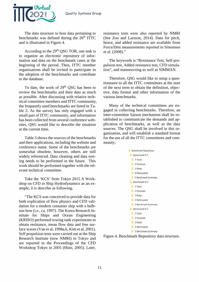
The data structure to host data pertaining to benchmarks was defined during the 26th ITTC and is illustrated in Figure 4.
According to the 29th QSG TOR, one task is to organize an electronic repository of infor-mation and data on the benchmark cases at the beginning of the period. Then, ITTC member organizations shall be invited to participate in the adoption of the benchmarks and contribute to the database.
To date, the work of 29th QSG has been to review the benchmarks and their data as much as possible. After discussing with relative tech-nical committee members and ITTC community, the frequently used benchmarks are listed in Ta-ble 2. As the survey has only engaged with a small part of ITTC community, and information has been collected from several conference web-sites, QSG would like to describe the situation at the current time.
Table 3 shows the sources of the benchmarks and their applications, including the website and conference name. Some of the benchmarks are somewhat obsolete, however, others are still widely referenced. Data cleaning and data sort-ing needs to be performed in the future. This work should be performed together with the rel-evant technical committee.
Take the ‘KCS’ from Tokyo 2015 A Work-shop on CFD in Ship Hydrodynamics as an ex-ample, it is describe as following.
“The KCS was conceived to provide data for both explication of flow physics and CFD vali-dation for a modern container ship with a bulb-ous bow (i.e., ca. 1997). The Korea Research In-stitute for Ships and Ocean Engineering (KRISO) performed towing tank experiments to obtain resistance, mean flow data and free sur-face waves (Van et al, 1998a,b, Kim et al, 2001). Self propulsion tests were carried out at the Ship Research Institute (now NMRI) in Tokyo and are reported in the Proceedings of the CFD Workshop Tokyo in 2005 (Hino, 2005). Later,
resistance tests were also reported by NMRI (See Zou and Larsson, 2014). Data for pitch, heave, and added resistance are available from Force/Dmi measurements reported in Simonsen et al. (2008).”
The keywords is “Resistance Test, Self-pro-pulsion test, Added resistance test, CFD simula-tion”, and manoeuvring as well as SIMMAN.
Therefore, QSG would like to setup a ques-tionnaire to all the ITTC committees at the start of the next term to obtain the definition, objec-tive, data format and other information of the various benchmarks.
Many of the technical committees are en-gaged in collecting benchmarks. Therefore, an inter-committee liaison mechanism shall be es-tablished to communicate the demands and ap-plication of benchmarks, as well as the data sources. The QSG shall be involved in this or-ganization, and will establish a standard format for the use of all the ITTC committees and com-munity.
Figure 4. Benchmark Repository data structure.
12
Quality Systems Group
Table 1. Comparison of local gravity for Example ITTC laboratories.
ITTC Laboratory Elevation (m)
Acceleration of Gravity, g (m/s2)
BGI BKG NGS PTB AMC, Newnham, TAS, Australia 21.0 9.80282 CSSRC, Wuxi, China 5.0 9.79439 HSVA, Hamburg, Germany 13.0 9.81378 9.80378 CNR-INM, Rome, Italy 55.0 9.80347
NSWCCD, Bethesda, MD, USA 41.2 40.0
9.80112
9.80108 9.80106
Table 2. Benchmark data used in technical fields.
Fields KCS JBC ONRT DTC DTMB 5415
KVLCC1 KVLCC2
Resistance and Propul-sion
● ● ● ●
Maneuvering ● ● ● ● ● Seakeeping ● ● ● Ocean Engineering Stability in Waves ● ●
Notes: the information is collected from several conference website, needed to be updated
Table 3. Benchmark data used in technical fields.
website Conference
KCS http://www.t2015.nmri.go.jp/kcs.html Tokyo 2015 A Workshop on CFD in Ship Hy-drodynamics
JBC https://t2015.nmri.go.jp/jbc.html Tokyo 2015 A Workshop on CFD in Ship Hy-drodynamics
ONRT https://t2015.nmri.go.jp/onrt.html Tokyo 2015 A Workshop on CFD in Ship Hy-drodynamics
DTC http://www.mashcon2019.ugent.be/EN/mash-con2019_call_EN.htm
5th International Conference on Ship Manoeu-vring in Shallow and Confined Water
dtmb 5415
https://simman2014.dk/ship-data/us-navy-com-batant/ SIMMAN 2014
KVLCC1
http://www.sim-man2008.dk/KVLCC/KVLCC1/tanker1.html SIMMAN 2008
KVLCC2
https://simman2014.dk/ship-data/moeri-kvlcc2-tanker/ SIMMAN 2014
Series http://www.shipstab.org/index.php/data-access (needs register) International Ship Stability Workshop
13
Quality Systems Group
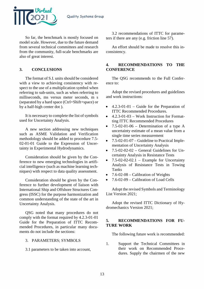
So far, the benchmark is mostly focused on model scale. However, due to the future demand from several technical committees and research from the community, full-scale benchmarks are also of great interest.
3. CONCLUSIONS
The format of S.I. units should be considered with a view to achieving consistency with re-spect to the use of a multiplication symbol when referring to sub-units, such as when referring to milliseconds, ms versus meter seconds, m s (separated by a hard space (Ctrl+Shift+space) or by a half-high center dot ).
It is necessary to complete the list of symbols used for Uncertainty Analysis.
A new section addressing new techniques such as ASME Validation and Verification methodology should be added to procedure 7.5-02-01-01 Guide to the Expression of Uncer-tainty in Experimental Hydrodynamics.
Consideration should be given by the Con-ference to new emerging technologies in artifi-cial intelligence (such as machine learning tech-niques) with respect to data quality assessment.
Consideration should be given by the Con-ference to further development of liaison with International Ship and Offshore Structures Con-gress (ISSC) for the purpose harmonization and common understanding of the state of the art in Uncertainty Analysis.
QSG noted that many procedures do not comply with the format required by 4.2.3-01-01 Guide for the Preparation of ITTC Recom-mended Procedures, in particular many docu-ments do not include the sections:
3. PARAMETERS; SYMBOLS
3.1 parameters to be taken into account,
3.2 recommendations of ITTC for parame-ters if there are any (e.g. friction line 57).
An effort should be made to resolve this in-consistency.
4. RECOMMENDATIONS TO THE CONFERENCE
The QSG recommends to the Full Confer-ence to:
Adopt the revised procedures and guidelines and work instructions:
• 4.2.3-01-01 – Guide for the Preparation of ITTC Recommended Procedures.
• 4.2.3-01-03 – Work Instruction for Format-ting ITTC Recommended Procedures
• 7.5-02-01-06 – Determination of a type A uncertainty estimate of a mean value from a single time series measurement
• 7.5-02-01-07 – Guideline to Practical Imple-mentation of Uncertainty Analysis
• 7.5-02-02-02 – General Guidelines for Un-certainty Analysis in Resistance Tests
• 7.5-02-02-02.1 – Example for Uncertainty Analysis of Resistance Tests in Towing Tanks
• 7.6-02-08 – Calibration of Weights • 7.6-02-09 – Calibration of Load Cells
Adopt the revised Symbols and Terminology List Version 2021;
Adopt the revised ITTC Dictionary of Hy-dromechanics Version 2021;
5. RECOMMENDATIONS FOR FU-TURE WORK
The following future work is recommended:
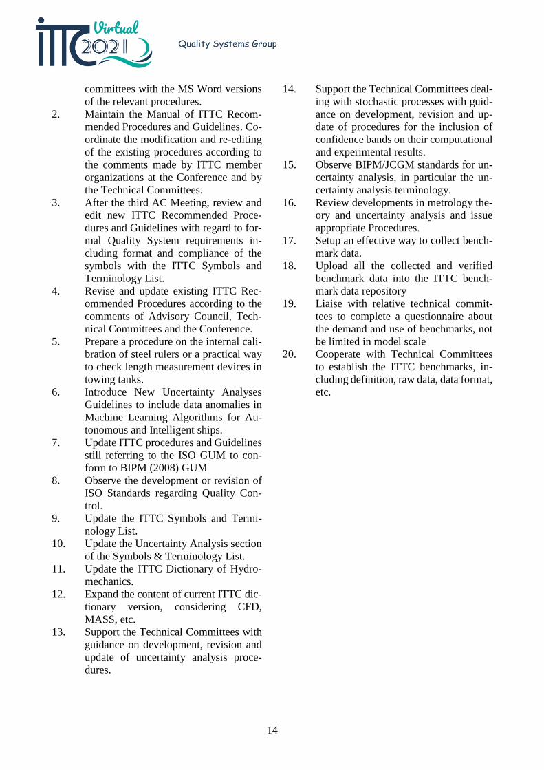
1. Support the Technical Committees in their work on Recommended Proce-dures. Supply the chairmen of the new
14
Quality Systems Group
committees with the MS Word versions of the relevant procedures.
2. Maintain the Manual of ITTC Recom-mended Procedures and Guidelines. Co-ordinate the modification and re-editing of the existing procedures according to the comments made by ITTC member organizations at the Conference and by the Technical Committees.
3. After the third AC Meeting, review and edit new ITTC Recommended Proce-dures and Guidelines with regard to for-mal Quality System requirements in-cluding format and compliance of the symbols with the ITTC Symbols and Terminology List.
4. Revise and update existing ITTC Rec-ommended Procedures according to the comments of Advisory Council, Tech-nical Committees and the Conference.
5. Prepare a procedure on the internal cali-bration of steel rulers or a practical way to check length measurement devices in towing tanks.
6. Introduce New Uncertainty Analyses Guidelines to include data anomalies in Machine Learning Algorithms for Au-tonomous and Intelligent ships.
7. Update ITTC procedures and Guidelines still referring to the ISO GUM to con-form to BIPM (2008) GUM
8. Observe the development or revision of ISO Standards regarding Quality Con-trol.
9. Update the ITTC Symbols and Termi-nology List.
10. Update the Uncertainty Analysis section of the Symbols & Terminology List.
11. Update the ITTC Dictionary of Hydro-mechanics.
12. Expand the content of current ITTC dic-tionary version, considering CFD, MASS, etc.
13. Support the Technical Committees with guidance on development, revision and update of uncertainty analysis proce-dures.
14. Support the Technical Committees deal-ing with stochastic processes with guid-ance on development, revision and up-date of procedures for the inclusion of confidence bands on their computational and experimental results.
15. Observe BIPM/JCGM standards for un-certainty analysis, in particular the un-certainty analysis terminology.
16. Review developments in metrology the-ory and uncertainty analysis and issue appropriate Procedures.
17. Setup an effective way to collect bench-mark data.
18. Upload all the collected and verified benchmark data into the ITTC bench-mark data repository
19. Liaise with relative technical commit-tees to complete a questionnaire about the demand and use of benchmarks, not be limited in model scale
20. Cooperate with Technical Committees to establish the ITTC benchmarks, in-cluding definition, raw data, data format, etc.
15
Quality Systems Group
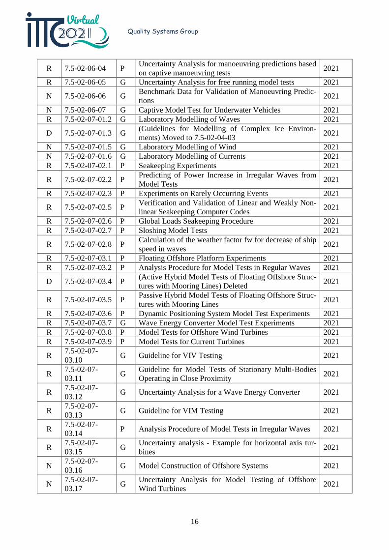
OUTCOME OF THE MANUAL OF ITTC RECOMMENDED PROCEDURES AND GUIDELINES MAINTENANCE.
New/ Rev./ Del
Number P /G Title
Effec-tive Date
R 1.0-06 G Guidelines for ITTC Conference Organisers 2021
R 4.2.3-01-01 P Guide for the Preparation of ITTC Recommended Proce-dures 2021
R 4.2.3-01-03 W Work Instruction for Formatting ITTC Recommended Procedures 2021
D 7.5-02-01-05 G (Model-Scale Propeller Cavitation Noise Measurements) Moved to 7.5-02-03-03.9 2021
R 7.5-02-01-06 P Determination of a type A uncertainty estimate of a mean value from a single time series measurement 2021
R 7.5-02-01-07 G Guideline to Practical Implementation of Uncertainty Analysis 2021
R 7.5-02-02-01 P Resistance Tests 2021
R 7.5-02-02-02 G General Guidelines for Uncertainty Analysis in Re-sistance Tests 2021
R 7.5-02-02-02.1 G Example for Uncertainty Analysis of Resistance Tests in Towing Tanks 2021
R 7.5-02-02-02.2 G Practical Guide for Uncertainty Analysis of Resistance Measurements in Routine Tests 2021
N 7.5-02-02-04 Wave Profile Measurement and Wave Pattern Re-sistance Analysis 2021
R 7.5-02-03-01.1 P Propulsion/ Bollard pull Test 2021
D 7.5-02-03-01.2 P (Uncertainty Analysis Example for Propulsion Test) De-leted 2021
R 7.5-02-03-01.3 PC Podded Propulsor Tests and Extrapolation 2021 R 7.5-02-03-01.4 P 1978 ITTC Performance Prediction Method 2021
R 7.5-02-03-01.7 P Performance Prediction Method for Unequally Loaded, Multiple Propeller Vessels 2021
R 7.5-02-03-01.8 G Scaling Method for ship wake fraction with pre-swirl de-vices 2021
R 7.5-02-03-02.1 P Open Water Test 2021
D 7.5-02-03-02.2 P (Uncertainty Analysis, Example for Open Water Test) Deleted 2021
R 7.5-02-03-03.9 G Model-Scale Propeller Cavitation Noise Measurements 2021 R 7.5-02-04-01 G General Guidance and Introduction to Ice Model Testing 2021 R 7.5-02-04-02 P Test Methods for Model Ice Properties 2021 R 7.5-02-04-02.3 PC Manoeuvring Tests in Ice 2021 R 7.5-02-04-03 G Guidelines for Modelling of Complex Ice Environments 2021 R 7.5-02-05-04 P Seakeeping Tests 2021 R 7.5-02-05-06 P Structural Loads 2021 D 7.5-02-05-07 P (Dynamic Instability Tests) Withdrawn 2021 R 7.5-02-06-01 P Free Running Model Tests 2021 R 7.5-02-06-02 P Captive Model Test Procedure 2021 R 7.5-02-06-03 P Validation of Manoeuvring Simulation Models 2021
16
Quality Systems Group
R 7.5-02-06-04 P Uncertainty Analysis for manoeuvring predictions based on captive manoeuvring tests 2021
R 7.5-02-06-05 G Uncertainty Analysis for free running model tests 2021
N 7.5-02-06-06 G Benchmark Data for Validation of Manoeuvring Predic-tions 2021
N 7.5-02-06-07 G Captive Model Test for Underwater Vehicles 2021 R 7.5-02-07-01.2 G Laboratory Modelling of Waves 2021
D 7.5-02-07-01.3 G (Guidelines for Modelling of Complex Ice Environ-ments) Moved to 7.5-02-04-03 2021
N 7.5-02-07-01.5 G Laboratory Modelling of Wind 2021 N 7.5-02-07-01.6 G Laboratory Modelling of Currents 2021 R 7.5-02-07-02.1 P Seakeeping Experiments 2021
R 7.5-02-07-02.2 P Predicting of Power Increase in Irregular Waves from Model Tests 2021
R 7.5-02-07-02.3 P Experiments on Rarely Occurring Events 2021
R 7.5-02-07-02.5 P Verification and Validation of Linear and Weakly Non-linear Seakeeping Computer Codes 2021
R 7.5-02-07-02.6 P Global Loads Seakeeping Procedure 2021 R 7.5-02-07-02.7 P Sloshing Model Tests 2021
R 7.5-02-07-02.8 P Calculation of the weather factor fw for decrease of ship speed in waves 2021
R 7.5-02-07-03.1 P Floating Offshore Platform Experiments 2021 R 7.5-02-07-03.2 P Analysis Procedure for Model Tests in Regular Waves 2021
D 7.5-02-07-03.4 P (Active Hybrid Model Tests of Floating Offshore Struc-tures with Mooring Lines) Deleted 2021
R 7.5-02-07-03.5 P Passive Hybrid Model Tests of Floating Offshore Struc-tures with Mooring Lines 2021
R 7.5-02-07-03.6 P Dynamic Positioning System Model Test Experiments 2021 R 7.5-02-07-03.7 G Wave Energy Converter Model Test Experiments 2021 R 7.5-02-07-03.8 P Model Tests for Offshore Wind Turbines 2021 R 7.5-02-07-03.9 P Model Tests for Current Turbines 2021
R 7.5-02-07-03.10 G Guideline for VIV Testing 2021
R 7.5-02-07-03.11 G Guideline for Model Tests of Stationary Multi-Bodies
Operating in Close Proximity 2021
R 7.5-02-07-03.12 G Uncertainty Analysis for a Wave Energy Converter 2021
R 7.5-02-07-03.13 G Guideline for VIM Testing 2021
R 7.5-02-07-03.14 P Analysis Procedure of Model Tests in Irregular Waves 2021
R 7.5-02-07-03.15 G Uncertainty analysis - Example for horizontal axis tur-
bines 2021
N 7.5-02-07-03.16 G Model Construction of Offshore Systems 2021
N 7.5-02-07-03.17 G Uncertainty Analysis for Model Testing of Offshore
Wind Turbines 2021
17
Quality Systems Group
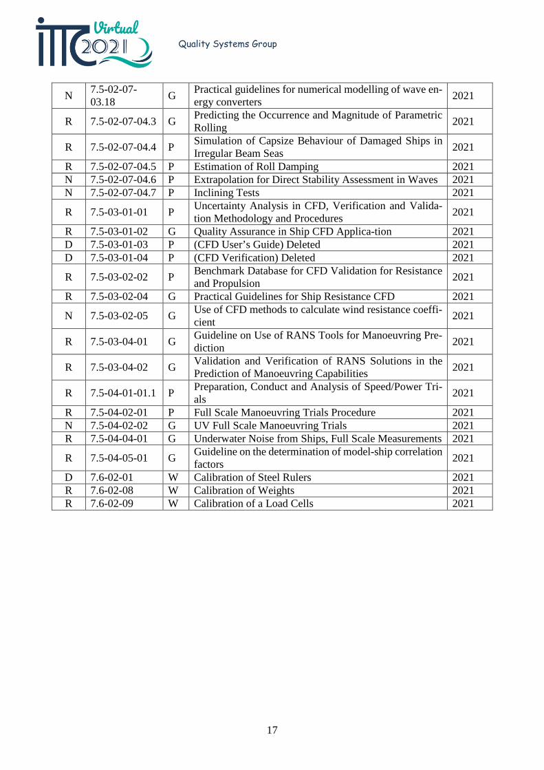
N 7.5-02-07-03.18 G Practical guidelines for numerical modelling of wave en-
ergy converters 2021
R 7.5-02-07-04.3 G Predicting the Occurrence and Magnitude of Parametric Rolling 2021
R 7.5-02-07-04.4 P Simulation of Capsize Behaviour of Damaged Ships in Irregular Beam Seas 2021
R 7.5-02-07-04.5 P Estimation of Roll Damping 2021 N 7.5-02-07-04.6 P Extrapolation for Direct Stability Assessment in Waves 2021 N 7.5-02-07-04.7 P Inclining Tests 2021
R 7.5-03-01-01 P Uncertainty Analysis in CFD, Verification and Valida-tion Methodology and Procedures 2021
R 7.5-03-01-02 G Quality Assurance in Ship CFD Applica-tion 2021 D 7.5-03-01-03 P (CFD User’s Guide) Deleted 2021 D 7.5-03-01-04 P (CFD Verification) Deleted 2021
R 7.5-03-02-02 P Benchmark Database for CFD Validation for Resistance and Propulsion 2021
R 7.5-03-02-04 G Practical Guidelines for Ship Resistance CFD 2021
N 7.5-03-02-05 G Use of CFD methods to calculate wind resistance coeffi-cient 2021
R 7.5-03-04-01 G Guideline on Use of RANS Tools for Manoeuvring Pre-diction 2021
R 7.5-03-04-02 G Validation and Verification of RANS Solutions in the Prediction of Manoeuvring Capabilities 2021
R 7.5-04-01-01.1 P Preparation, Conduct and Analysis of Speed/Power Tri-als 2021
R 7.5-04-02-01 P Full Scale Manoeuvring Trials Procedure 2021 N 7.5-04-02-02 G UV Full Scale Manoeuvring Trials 2021 R 7.5-04-04-01 G Underwater Noise from Ships, Full Scale Measurements 2021
R 7.5-04-05-01 G Guideline on the determination of model-ship correlation factors 2021
D 7.6-02-01 W Calibration of Steel Rulers 2021 R 7.6-02-08 W Calibration of Weights 2021 R 7.6-02-09 W Calibration of a Load Cells 2021
18
Quality Systems Group
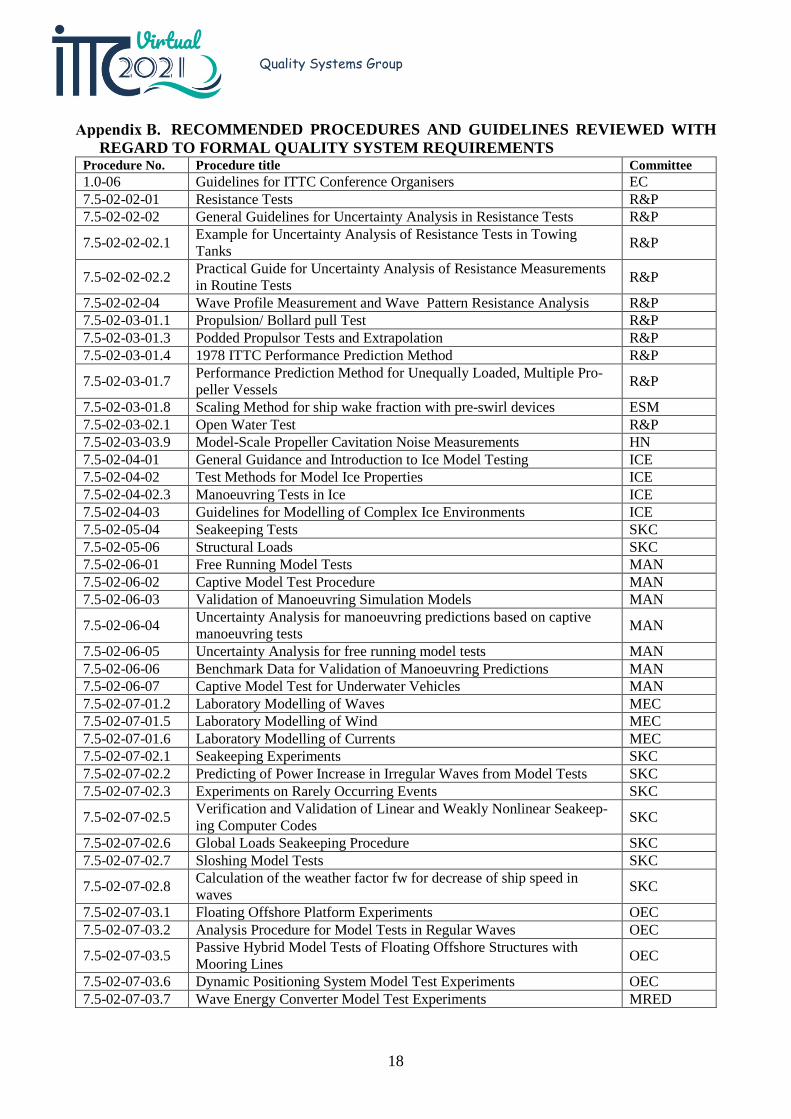
RECOMMENDED PROCEDURES AND GUIDELINES REVIEWED WITH REGARD TO FORMAL QUALITY SYSTEM REQUIREMENTS
Procedure No. Procedure title Committee 1.0-06 Guidelines for ITTC Conference Organisers EC 7.5-02-02-01 Resistance Tests R&P 7.5-02-02-02 General Guidelines for Uncertainty Analysis in Resistance Tests R&P
7.5-02-02-02.1 Example for Uncertainty Analysis of Resistance Tests in Towing Tanks R&P
7.5-02-02-02.2 Practical Guide for Uncertainty Analysis of Resistance Measurements in Routine Tests R&P
7.5-02-02-04 Wave Profile Measurement and Wave Pattern Resistance Analysis R&P 7.5-02-03-01.1 Propulsion/ Bollard pull Test R&P 7.5-02-03-01.3 Podded Propulsor Tests and Extrapolation R&P 7.5-02-03-01.4 1978 ITTC Performance Prediction Method R&P
7.5-02-03-01.7 Performance Prediction Method for Unequally Loaded, Multiple Pro-peller Vessels R&P
7.5-02-03-01.8 Scaling Method for ship wake fraction with pre-swirl devices ESM 7.5-02-03-02.1 Open Water Test R&P 7.5-02-03-03.9 Model-Scale Propeller Cavitation Noise Measurements HN 7.5-02-04-01 General Guidance and Introduction to Ice Model Testing ICE 7.5-02-04-02 Test Methods for Model Ice Properties ICE 7.5-02-04-02.3 Manoeuvring Tests in Ice ICE 7.5-02-04-03 Guidelines for Modelling of Complex Ice Environments ICE 7.5-02-05-04 Seakeeping Tests SKC 7.5-02-05-06 Structural Loads SKC 7.5-02-06-01 Free Running Model Tests MAN 7.5-02-06-02 Captive Model Test Procedure MAN 7.5-02-06-03 Validation of Manoeuvring Simulation Models MAN
7.5-02-06-04 Uncertainty Analysis for manoeuvring predictions based on captive manoeuvring tests MAN
7.5-02-06-05 Uncertainty Analysis for free running model tests MAN 7.5-02-06-06 Benchmark Data for Validation of Manoeuvring Predictions MAN 7.5-02-06-07 Captive Model Test for Underwater Vehicles MAN 7.5-02-07-01.2 Laboratory Modelling of Waves MEC 7.5-02-07-01.5 Laboratory Modelling of Wind MEC 7.5-02-07-01.6 Laboratory Modelling of Currents MEC 7.5-02-07-02.1 Seakeeping Experiments SKC 7.5-02-07-02.2 Predicting of Power Increase in Irregular Waves from Model Tests SKC 7.5-02-07-02.3 Experiments on Rarely Occurring Events SKC
7.5-02-07-02.5 Verification and Validation of Linear and Weakly Nonlinear Seakeep-ing Computer Codes SKC
7.5-02-07-02.6 Global Loads Seakeeping Procedure SKC 7.5-02-07-02.7 Sloshing Model Tests SKC
7.5-02-07-02.8 Calculation of the weather factor fw for decrease of ship speed in waves SKC
7.5-02-07-03.1 Floating Offshore Platform Experiments OEC 7.5-02-07-03.2 Analysis Procedure for Model Tests in Regular Waves OEC
7.5-02-07-03.5 Passive Hybrid Model Tests of Floating Offshore Structures with Mooring Lines OEC
7.5-02-07-03.6 Dynamic Positioning System Model Test Experiments OEC 7.5-02-07-03.7 Wave Energy Converter Model Test Experiments MRED
19
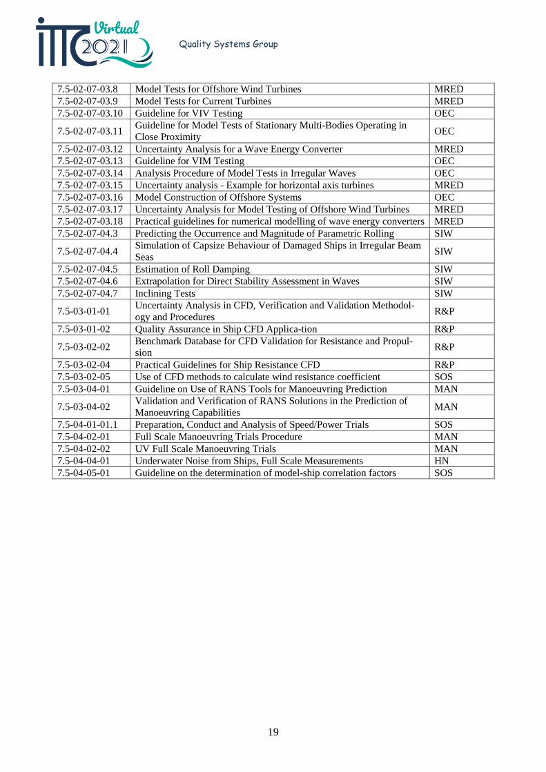
Quality Systems Group
7.5-02-07-03.8 Model Tests for Offshore Wind Turbines MRED 7.5-02-07-03.9 Model Tests for Current Turbines MRED 7.5-02-07-03.10 Guideline for VIV Testing OEC
7.5-02-07-03.11 Guideline for Model Tests of Stationary Multi-Bodies Operating in Close Proximity OEC
7.5-02-07-03.12 Uncertainty Analysis for a Wave Energy Converter MRED 7.5-02-07-03.13 Guideline for VIM Testing OEC 7.5-02-07-03.14 Analysis Procedure of Model Tests in Irregular Waves OEC 7.5-02-07-03.15 Uncertainty analysis - Example for horizontal axis turbines MRED 7.5-02-07-03.16 Model Construction of Offshore Systems OEC 7.5-02-07-03.17 Uncertainty Analysis for Model Testing of Offshore Wind Turbines MRED 7.5-02-07-03.18 Practical guidelines for numerical modelling of wave energy converters MRED 7.5-02-07-04.3 Predicting the Occurrence and Magnitude of Parametric Rolling SIW
7.5-02-07-04.4 Simulation of Capsize Behaviour of Damaged Ships in Irregular Beam Seas SIW
7.5-02-07-04.5 Estimation of Roll Damping SIW 7.5-02-07-04.6 Extrapolation for Direct Stability Assessment in Waves SIW 7.5-02-07-04.7 Inclining Tests SIW
7.5-03-01-01 Uncertainty Analysis in CFD, Verification and Validation Methodol-ogy and Procedures R&P
7.5-03-01-02 Quality Assurance in Ship CFD Applica-tion R&P
7.5-03-02-02 Benchmark Database for CFD Validation for Resistance and Propul-sion R&P
7.5-03-02-04 Practical Guidelines for Ship Resistance CFD R&P 7.5-03-02-05 Use of CFD methods to calculate wind resistance coefficient SOS 7.5-03-04-01 Guideline on Use of RANS Tools for Manoeuvring Prediction MAN
7.5-03-04-02 Validation and Verification of RANS Solutions in the Prediction of Manoeuvring Capabilities MAN
7.5-04-01-01.1 Preparation, Conduct and Analysis of Speed/Power Trials SOS 7.5-04-02-01 Full Scale Manoeuvring Trials Procedure MAN 7.5-04-02-02 UV Full Scale Manoeuvring Trials MAN 7.5-04-04-01 Underwater Noise from Ships, Full Scale Measurements HN 7.5-04-05-01 Guideline on the determination of model-ship correlation factors SOS
20
Quality Systems Group
DOCUMENTS UPDATED BY QSG Number P / G Title 4.2.3-01-01 P Guide for the Preparation of ITTC Recommended Procedures 4.2.3-01-03 W Work Instruction for formatting ITTC Recommended Procedures and Guidelines
7.5-02-01-06 P Determination of a type A uncertainty estimate of a mean value from a single time series measurement
7.5-02-01-07 G Guideline to Practical Implementation of Uncertainty Analysis 7.5-02-02-02 G General Guideline for Uncertainty Analysis in Resistance Tests 7.5-02-02-02.1 G Example for Uncertainty Analysis of Resistance Tests in Towing Tanks 7.6-02-08 W Calibration of Weights 7.6-02-09 W Calibration of Load Cells
P = Procedure G = Guideline W = Work Instruction