Embed Size (px)
Citation preview
D5-13183
Final Report - Studies of Improved Saturn V Vehicles and Intermediate Payload Vehicles (P-115)
SUMMARY
Prepared for NASA - George C. Marshall Space Flight Center under Contract NAS&-20266
INDEXING DATA October 7, 1966 DATE OPR # T PGM SUBJECT
SfGNATOR LOC
s;
THE BOEING COMPANY - SPACE DIVISION
STUDIES OF IMPROVED SATURN V VEHICLES AND I N T E R M E D I A T E PAYLOAD SATURN VEHICLES (P-115)
SUMMARY DOCUMENT D5-13183
FINAL R E P O R T P R E P A R E D UNDER CONTRACT NUMBER NAS8-20266
SUBMITTED T O GEORGE C. MARSHALL S P A C E FLIGHT C E N T E R
NATIONAL AERONAUTICS AND S P A C E ADMINISTRATION OCTOBER 7, 1966
SUBMITTED BY SYSTEMS ANALYSIS CONTRACTOR
T H E BOEING COMPANY S P A C E DIVISION
L A U N C H SYSTEMS BRANCH H U N T S V I L L E , ALABAMA
D5-13183
FOREWORD
Th i s vo lume s u m m a r i z e s five t e c h n i c a l Vehic le D e s c r i p t i o n D o c u m e n t s r e p o r t i n g a t e n - m o n t h s tudy to p r e p a r e t e c h n i c a l and r e s o u r c e da t a on u p r a t e d payload Sa tu rn V and i n t e r m e d i a t e payload Sa tu rn v e h i c l e s . Th i s s tudy i s p a r t of a cont inuing effort by the Na t iona l A e r o n a u t i c s and Space A d m i n i s t r a t i o n (NASA) to i n v e s t i g a t e the capabi l i ty and f lexibi l i ty of the Sa tu rn V launch v e h i c l e and to identify p r a c t i c a l m e t h o d s for d ive r s i f i ed u t i l i za t ion of i t s payload capab i l i t y . NASA C o n t r a c t NAS8 -20266 a u t h o r i z e s the work r e p o r t e d h e r e i n and w a s s u p e r v i s e d and a d m i n i s t e r e d by the M a r s h a l l Space F l i g h t C e n t e r (MSFC) . S-II da t a w a s supp l i ed by the Space and I n f o r m a t i o n Divis ion of N o r t h A m e r i c a n Avia t ion . S-IVB da ta was suppl ied by the M i s s i l e and Space S y s t e m s Div i s ion of Douglas A i r c r a f t Company . L a u n c h s y s t e m da ta was supp l i ed by the Denve r Div i s ion of The M a r t i n Company- Solid m o t o r da t a w e r e suppl ied by Uni ted Technology C o r p o r a t i o n . The L a u n c h S y s t e m s B r a n c h , A e r o s p a c e Group , Space Div i s ion of The Boeing Company was the S y s t e m s Ana lys i s c o n t r a c t o r for t h i s s tudy.
P r o g r a m documen ta t i on i n c l u d e s a s u m m a r y volume (this d o c u m e n t ) , five v o l u m e s cove r ing v e h i c l e d e s c r i p t i o n s , r e s e a r c h and technology i m p l i c a t i o n s r e p o r t , and a cos t documen t . Individual de s igna t i ons a r e a s fol lows:
D5-13183 S u m m a r y D o c u m e n t ' D5-13183-1 V e h i c l e D e s c r i p t i o n M L V - S A T - I N T - 2 0 , -21
D5-13183-2 Veh ic l e D e s c r i p t i o n M L V - S A T - V - 3 B D5-13183-3 V e h i c l e D e s c r i p t i o n M L V - S A T -V-25(S) D5-13183-4 Veh ic l e D e s c r i p t i o n M L V - S A T - V - 4 ( S ) B D5-13183.-5 V e h i c l e D e s c r i p t i o n MLV-SAT -V-23(L) D5-13183-6 R e s e a r c h and Techno logy I m p l i c a t i o n s R e p o r t D5-13183-7 F i r s t Stage Cos t P l a n
i i

D5-13183
ABSTRACT
This document summar izes a study conducted under NASA/MSFC Contract NAS8-20266, "Studies of Improved Saturn V Vehicles and Intermediate Payload Saturn Vehicles (P-115)", from December 6, 1965 to October 7, 1966. The details of this study a r e contained in five "Vehicle Description Documents" (D5-13183-1, -2, - 3 , -4, and -5). Phase I of the study was a pa rame t r i c performance and resources analysis to select one baseline configuration for each of the six vehicles, Phase II of the study included a fluid and flight mechanics study, design impact on systems', and a resources analysis for each baseline vehicle. The uprated vehicles a r e feasible configurations and logical candidates for payloads in excess of the current Saturn V capability. No major problem a rea s were identified for ei ther development or production. The intermediate payload vehicle derivatives of Saturn V" a re a logical means of providing orbital payload capability between that of the Saturn I and the two-stage Saturn V.
KEY WORDS
Contract NAS8-20266 D5-13183 Vehicle Description Document Saturn V NASA /MSFC. Up rating Trade Studies Payload to 72 Hour Lunar Injection
Fluid and Flight Mechanics Impact Resources Cost Payload to 100 NM orbit MLV-INT Basel ine Configuration MLV-SAT-V
iii

D5-13183
T A B L E O F CONTENTS
SECTION
FOREWARD ABSTRACT 1.0 INTRODUCTION 2 . 0 SUMMARY 3. 0 GUIDE LINES AND ASSUMPTIONS 4 . 0 M L V - S A T - I N T - 2 0 / - 2 0 LAUNCH VEHICLES 5. 0 M L V - S A T - V - 3 B LAUNCH VEHICLES 6.0. MLV-SAT-V-25(S) LAUNCH VEHICLES 7 .0 M L V - 5 A T - V - 4 ( S ) B 8..0 M L V - S A T - V - 2 3 ( L ) LAUNCH VEHICLE 9. 0 CONCLUSIONS AND RECOMMENDATIONS
iv
D 5 - 1 3 I 8 3
FIGURES
FIGURE NO. P A G E
1-1 PHASE I LAUNCH VEHICLE CANDIDATES 2 1-2 S E L E C T E D BASELINE LAUNCH V E H I C L E S FOR PHASE
II STUDY E F F O R T 4 2 - 1 VEHICLE COMPARISON 7 2 - 2 UPRATED VEHICLE INVESTMENT COST COMPARISON 8 2 - 3 T W O - S T A G E VEHICLE COST E F F I C I E N C Y 8 2 - 4 T H R E E - S T A G E VEHICLE COST E F F I C I E N C Y 9 4 -1 INT V E H I C L E S 14 4-2 INT - 2 0 / - 2 1 VEHICLE COMPARISON 17 4 - 3 FOUR ENGINE S- IC-20 STAGE 19 4 - 4 I N T - 2 0 ORBIT ALTITUDE - AZIMUTH PAYLOAD
CAPABILITY 20 4 - 5 I N T - 2 1 ORBIT ALTITUDE - A Z I M U T H PAYLOAD
CAPABILITY 21 4-6 INT-20 P O L A R & SUN SYNCHRONOUS PAYLOAD
(DIRECT ASCENT) 21 4 -7 SYNCHRONOUS ORBIT PAYLOAD CAPABILITY 21 4 - 8 I N T - 2 0 / - 2 1 VEHICLE D E V E L O P M E N T AND DELIVERY
P L A N 22 4 -9 INT VEHICLE COST EFFICIENCY COMPARISON 24 5-1 M L V - S A T - V - 3 B BASELINE LAUNCH VEHICLE 26 5-2 TRADE STUDY U P P E R STAGE ENGINES 28 5-3 TRADE STUDY P E R F O R M A N C E DATA 29 5-4 TRADE STUDY VEHICLE PAYLOAD COMPARISON 29 5-5 S A T - V - 3 B & I N T - 1 7 COST E F F I C I E N C Y TRADE 30 5-6 ORBIT A L T I T U D E - AZIMUTH PAYLOAD CAPABILITY 31 5-7 HIGH ENERGY PAYLOAD CAPABILITY 32 5-8 T W O - S T A G E P O L A R & SUN SYNCHRONOUS ORBIT
PAYLOAD CAPABILITY 33 5-9 T H R E E - S T A G E P O L A R & SUN SYNCHRONOUS ORBIT
PAYLOAD CAPABILITY 33 5-10 ACOUSTIC ENVIRONMENT AND STRUCTURAL LOADS 34 5-11 SAT-V-4(S)B VEHICLE IMPACT 35 5-12 S A T - V - 3 B V E H I C L E D E V E L O P M E N T AND DELIVERY
PLAN 38 6 -1 M L V - S A T - V - 2 5 ( S ) BASELINE V E H I C L E 40 6-2 P E R F O R M A N C E TRADE DATA 41 6-3 COST E F F I C I E N C Y TRADE DATA 42 6-4 ACOUSTIC ENVIRONMENT AND STRUCTURAL LOADS 46 6-5 SAT-V-25(S) VEHICLE IMPACT 47
v
D5-13183
FIGURES (Continued)
FIGURE NO. PAGE
6-6 MOBILE ERECTION AND PROCESSING STRUCTURE 51 6-7 SAT-V-25(S) LAUNCH VEHICLE DEVELOPMENT AND
DELIVERY PLAN 53 7-1 MLV-SAT-V-4(S)B BASELINE VEHICLE 54 7-2 TRADE STUDY PERFORMANCE DATA 55 7-3 TRADE STUDY COST DATA 57 7-4 ORBIT ALTITUDE - AZIMUTH PAYLOAD CAPABILITY 58 7-5 POLAR & SUN SYNCHRONOUS ORBIT PAYLOAD
CAPABILITY 60 '7-6 THREE-STAGE HIGH ENERGY MISSION CAPABILITY 60 7-7 TWO-STAGE WIND/PAYLOAD SENSITIVITY 62 7-8 THREE-STAGE WIND/PAYLOAD SENSITIVITY 62 7-9 ACOUSTIC ENVIRONMENT AND STRUCTURAL LOADS 64 7-10 SAT-V-4(S)B VEHICLE IMPACT 65 7-11 MOBILE ASSEMBLY AND HANDLING STRUCTURE 68 7-12 SAT-V-4(S)B VEHICLE DEVELOPMENT AND
DELIVERY PLAN 69 7-13 COST EFFICIENCY COMPARISON 70 8-1 SAT-V-23(L) BASELINE VEHICLE 72 8-2 SAT-V-23(L) TRADE STUDY PERFORMANCE DATA 74 8-3 SAT-V-24(L) TRADE STUDY PERFORMANCE DATA 75 8-4 LIQUID PROPELLANT POD DESIGN 76 8-5 ACOUSTIC ENVIRONMENT AND STRUCTURAL LOADS 78 8-6 SAT-V-23(L) VEHICLE IMPACT 80 8-7 SAT-V-23(L) VEHICLE DEVELOPMENT AND
DELIVERY PLAN 84
vi
D 5 - I 3 1 8 3
T A B L E S
T A B L E NO. T I T L E P A G E
4-1 I N T E R M E D I A T E VEHICLE P E R F O R M A N C E SUMMARY 16 4-II SIGNIFICANT LOAD CRITERIA 20 4-III I N T - 2 0 COST SUMMARY 23 4-IV I N T - 2 1 COST SUMMARY 23 5-1 SIGNIFICANT LOAD CRITERIA 30 5-II S A T - V - 3 B COST SUMMARY 38 6-1 P A Y L O A D CAPABILITY 44 6-II SIGNIFICANT LOAD CRITERIA 45 6 - i n SAT-V-25(S) COST SUMMARY 53 7-1 SOLID MOTOR CHARACTERISTICS 56 7-II P A Y L O A D CAPABILITY 59 7-III SIGNIFICANT LOAD CRITERIA 61 7-IV SAT-V-4 (S )B COST SUMMARY 70 8-1 T H R E E - S T A G E 72-HOUR LUNAR INJECTION PAYLOAD
C A P A B I L I T Y 77 8-II SIGNIFICANT LOAD CRITERIA 77 8-UI S A T - V - 2 3 ( L ) COST SUMMARY 84
VI1

D5-13183
1.0 INTRODUCTION
This study is par t of a continuing effort by NASA to identify a spectrum of prac t ica l launch vehicles to meet future payload and miss ion requi rements a s they become defined. The launch vehicles studied under Contract NAS8-20266 cover a payload range between the existing Saturn IB and the Saturn V (intermediate payload vehicles) and a payload range beyond the existing Saturn V capabilities (uprated Saturn V vehicles)
The vehicles studied were combinations of existing or modified Saturn V s tages ; some vehicles a lso included boos t -ass i s t components. A pr imary study requirement was to make maximum use of existing Saturn technology and support equipment.
In general , the NAS8-20266 study program objectives were to:
a. Select feasible and cost effective baseline vehicles from each of severa l ca tegor ies .
b . P r e p a r e sufficient technical data to define vehicle environments, design, capabil i t ies, and charac te r i s t i c s .
c. Define support system requ i rements .
d. Determine the date that the f i rs t flight a r t i c le could be available within study ground ru l e s .
e. Es t imate cost required for implementation of the system plus production of th i r ty flight a r t i c les in five yea r s .
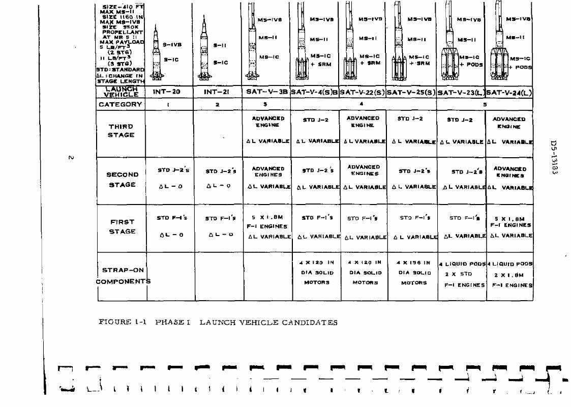
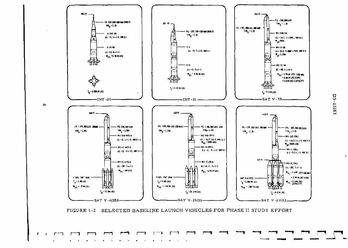
There were two phases of study work. Phase I was a twelve-week effort in which candidate vehicle performance and pre l iminary cost t rade studies were conducted to select a feasible and cost effective basel ine vehicle f rom each of five categories (shown in Figure 1-1). An additional basel ine vehicle was la ter added from Category 4.
For each of the six baseline vehicles selected (see Figure 1-2), Phase II directed the effort to defining ground and flight environments, defining system design and resource impact for each stage and the total vehicle, and determining vehicle miss ion capabilities and cha rac te r i s t i c s .
The launch vehicles in Categories 1 and 2 a r e Saturn V stage combinations for miss ions in the payload range between the current Saturn IB and Saturn V payload capability. The launch vehicles in
1
S i Z E - 4 1 0 FT MAX M S - H SIZE 1160 I N
MAX M S - I V B SIZE S30K PROPELLANT AT MR 5 !l
MAX PAYLOAC 5 L B / F T 3
( 2 STS) II L B / F T 3
(3 STO) STO:STANDARC £>L= CHANGE IN STAGE LENGTt-
3-11
S - I C
M S - I V B
m
MS-II
MS—IC ! A
1
M S - I V B
M S - I I
M S - I C
+ SRM 0A
mm
M S - I V B
M S - l l
M S - I C + SRM frfa
LAUNCH VEHICLE INT- 20 INT-21 S A T - V - 3 B SAT-V-4(S)B SAT-V-22(S> SAT-
CATEGORY
ro
THIRD STAGE
ADVANCED ENGINE
h L VARIABLE
STO J - 2
H L VARIABLE
ADVANCED ENGINE
A L VARIABLE
S T D
A L V
SECOND
STAGE
STD J - 2 s
A L - O
STD J - 2 S
A L - 0
ADVANCED ENGINES
A L VARIABLE
STD J - 2 S
& L VARIABLE
ADVANCED ENGINES
A L VARIABLE
ST
6 L V
FIRST STAGE
STD F-Ts
AL. - 0
STD F - l S
a L. - o
5 X I .BM
F - l ENGINES
A L VARIABLE
STD F- l S STO F- i 's
A L VARIABLE t L VAHIABLE
ST
A L
STRAP-ON
COMPONENTS
4 X 1 2 0 IN
DIA SOLID
MOTORS
4 X 120 IN
DIA SOLID
MOTORS
4 X
DIA
M
F I G U R E 1-1 P H A S E I LAUNCH V E H I C L E CANDIDATES
•L—\ L } I I 1 I i I I i i • I • l /

D5-13183
C a t e g o r i e s 3 , 4, and 5 a r e advanced Sa tu rn V conf igura t ions with pay load c a p a b i l i t i e s beyond tha t of the ex i s t ing Sa tu rn V-
The five c a t e g o r i e s of v e h i c l e s a r e :
C a t e g o r y 1 (MLV-SAT- INT -20) du r ing P h a s e I w a s a f ami ly of t w o - s t a g e l aunch v e h i c l e c a n d i d a t e s wi th s t a n d a r d s i z e S- IC a n d S-IVB s t a g e s us ing s t a n d a r d F - l engines ( t h r e e , four , and five) and a s t a n d a r d J - 2 eng ine . A s ing le b a s e l i n e launch vehic le ( F i g u r e 1-2) w a s s e l ec t ed for t he P h a s e II s tudy effor t .
C a t e g o r y 2 (MLV-SAT-1NT-21) dur ing P h a s e I w a s a f ami ly of t w o - s t a g e launch v e h i c l e cand ida t e s wi th s t a n d a r d s ize S-IC and S-II s t a g e s us ing s t a n d a r d F - l eng ines ( t h r e e , four , and five) and J - 2 eng ines ( t h r e e , four , and f ive) . A s ingle b a s e l i n e l aunch vehic le ( F i g u r e 1-2) w a s s e l e c t e d for the P h a s e II study effor t .
C a t e g o r y 3 (MLV -SAT-V-3B) du r ing P h a s e I w a s a f ami ly of t w o -and t h r e e - s t a g e l a u n c h veh ic le cand ida t e s with modi f ied u p r a t e d Sa tu rn V s t a g e s us ing v a r i o u s t y p e s , n u m b e r s , and t h r u s t l e v e l s of advanced eng ines in the u p p e r s t a g e s and u p r a t e d F - l eng ines in the modif ied S-IC s t a g e . A s ing le b a s e l i n e l aunch veh ic le ( F i g u r e 1-2) w a s s e l e c t e d for the P h a s e II s tudy effor t .
C a t e g o r y 4 inc luded modif ied S a t u r n V launch v e h i c l e s with s t r a p - o n so l id b o o s t - a s s i s t c o m p o n e n t s . T h r e e f a m i l i e s o£ v e h i c l e s w e r e s tudied a s follow:s:
a . MJ_,V-SAT-V-4(S)B dur ing P h a s e I w a s a f ami ly of t w o - and t h r e e -s t age l aunch v e h i c l e s wi th modi f ied S a t u r n V s t a g e s , s t a n d a r d F - l and J - 2 eng ines with s t r a p - O n 120-inch d i a m e t e r (five, s ix , and seven segmen t ) so l id m o t o r s . A s ingle b a s e l i n e launch veh ic le ( F i g u r e 1-2) w a s s e l e c t e d for the P h a s e II s tudy effort .
b . M L V - S A T - V - 2 2 ( S ) du r ing P h a s e I w a s a f ami ly of t w o - and t h r e e -s t age launch v e h i c l e s with modi f ied Sa tu rn V s t a g e s us ing v a r i o u s t y p e s , n u m b e r s , and t h r u s t l eve l s of advanced eng ines in the upper s t a g e s , a modi f ied S-IC s t a g e wi th s t a n d a r d F - l eng ines in the f i r s t s t age , and s t r a p - o n 120- inch d i a m e t e r (five, s ix , and s e v e n segmen t ) so l id m o t o r s . No l aunch veh ic le in t h i s fami ly w a s s tud ied beyond P h a s e I ,
c. M L V - S A T - V - 2 5 ( S ) dur ing P h a s e I w a s a fami ly of t w o - and t h r e e -s t age l aunch v e h i c l e s with modi f ied Sa tu rn V s t a g e s , s t a n d a r d F - l and J - 2 e n g i n e s , and s t r a p - o n 156- inch d i a m e t e r (two and t h r e e segment ) so l id m o t o r s . A s ing le b a s e l i n e launch veh ic l e ( F i g u r e 1-2) was s e l ec t ed for the P h a s e II s tudy effor t .
3
I
am
pii»,wnu»wn«tm
S- IV I •»
S-IC-M
-INT -20-
<WFT.
•4.-JN.S00US HUM
I S C 1» - 5RF*
J
A
m
-Pl-M.WLOT I * ( • LW
-M5-fVt-*5ll IL-ft H R W S ' I
41-0, J i J - l , MR S-1
-"S-ICIISII
1L-W, 5.F-1
T -1J.WLIS
•SAT V - 4 ( S ) B -
K 1 . F 1 -
<H-&Ma>iigoMM{Mim
&
5-11 11 -H-Sij-I. MRH
• s-ic U - t t ) iF - |
INT-21-
410 FT
/ *
pl**n,¥MiMsitoHto.—
4
1 SfO, 1W' » M
l0 '4.(W[»S
w p s - i IUW.IBS
vU
A
- PH.- m . w i n tOR im,-i.m
*L» l&S'Ul-J.MR.H
-MWI-lSSt H -1 Si J-!. MB W
•M5-IC-25ISI
A Al-«.S'.*iF-l
Wp, -fcUtUBS
y v - S A T V-25 {S ) -
P l .KT ,«a
M - W
Hff'JIA
w p f •
FIGURE 1-2 SELECTED BASELINE LAUNCH VEHICLES FOR PHASE I
1

D5 -13183
Category 5 included modified Saturn V launch vehicles with s t rap-on boos t -ass i s t liquid propellant pods. Two families of vehicles were studied as follows:
a. MLV-S.AT-V-23(L.) during Phase I was a family of two- and t h r e e -stage launch, vehicles with modified Saturn V s tages , standard F - l and J -2 engines and four s t rap-on liquid propellant pods each using two standard F - l engines. A single baseline launch vehicle (Figure 1-2) was selected for the Phase II study effort.
b. MLV-SAT -V-24(1,) during Phase I was a family of two- and t h r e e -stage launch vehicles with modified Saturn V stages using various types, numbers , and thrust levels of advanced engines in the upper stages, a modified S-IC stage with 1, 800, 000 pound F - l engines, and four liquid propellant pods each containing two 1,800,000 pound F - l engines. No launch vehicles in this family were studied beyond Phase I.
5

D5-13183
a
D5-13183
2 . 0 SUMMARY
INTERMEDIATES
• M747M 12/YR. PRODUCTION
CM BfYR. PRODUCTION U « Sfffi. PRODUCTION
SINGLE COST FOR SYMW.TANEOUS IMPLEMENTATION
OFM1S-2Q/-21 ENGINE/STAGE COMBINATIONS
m-
UPRATED SATURN V'S
INT-20 (2STGI F-l
INT-21 (2ST6I F-IJJ-2
SATV-3B 2 STG 3 STG
SATV-4ISIB 2 STG 3 STG
SAT V-2SSI 2 STG 3STG
SAT V-Z3HI 2 STG 1 STG
PAYLOAD KLB
3 4 78 132
*~l M " 52 W *S
IV Wt IH n? !«• TV- 3*7 141 380 139 m W 579 Z20
BOTH - m • r
1(87.4 431.4 403.1 941.9
R&O RIGHTVffllCUS-JM lit ec.i 0 JS.4 279.1 324 Z 4a o
AVG. OPERATIONAL UNIT COST - IM 40.5 74 4 1U.7 139.0 105.1 124 a 109.6 131.0 142.5 1418
OPERATIONAL COST EFFICIENCY-Mil «8 292 m su 276 844 ZZ2 494 H6 7«
:IRSTDaiWBYIATP-JAN6S AS-516FU70 ASS16FEB70 AS-537SCPT'73 AS-5Z4 JUNE -71 AS-5M.lU.r71 AS-SSWAV'73
FIGURE 2-1 VEHICLE COMPARISON
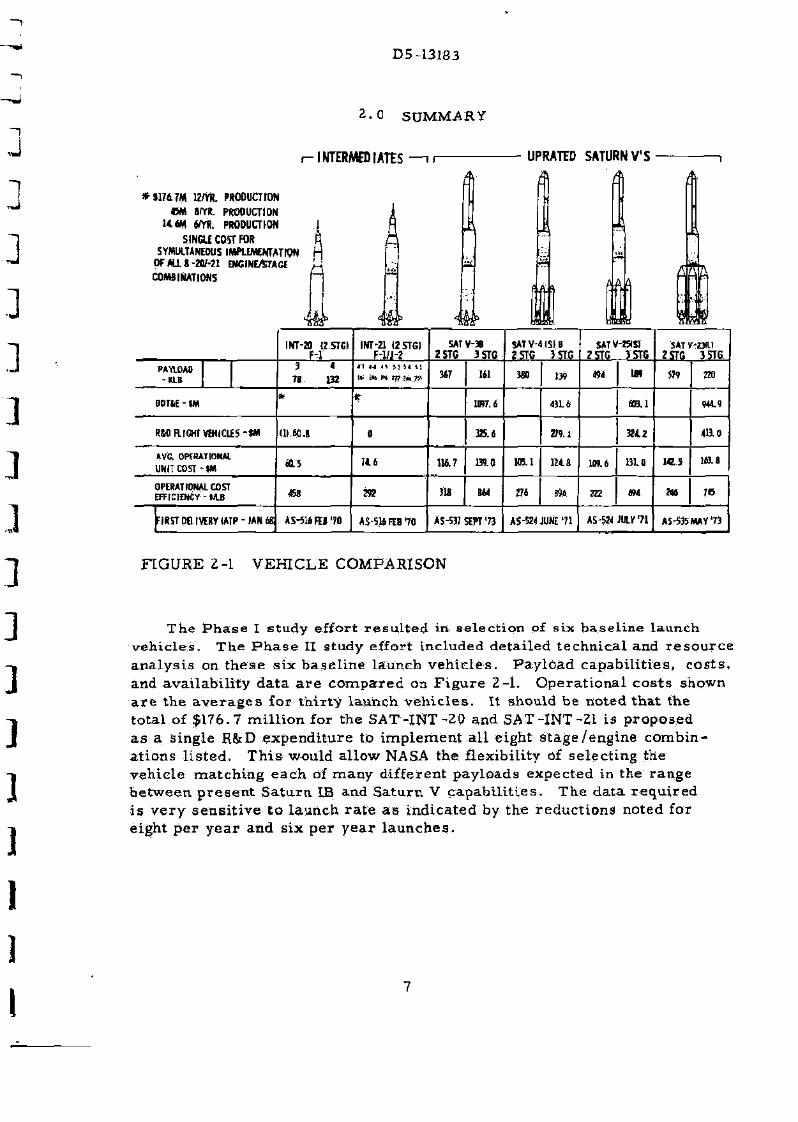
The Phase I study effort resul ted in selection of six baseline launch vehicles. The Phase II study effort included detailed technical and resource analysis on these six baseline launch vehicles. Payload capabilities, costs , and availability data a r e compared on Figure 2-1. Operational costs shown a r e the averages for thirty launch vehicles . It should be noted that the total of $176.7 mill ion for the SAT -INT -20 and SAT-INT-21 is proposed as a single R&D expenditure to implement all eight stage/engine combinations l isted. This would allow NASA the flexibility of selecting the vehicle matching each of many different payloads expected in the range between present Saturn IB and Saturn V capabil i t ies . The data required is very sensitive to launch ra te as indicated by the reductions noted for eight per year and six per year launches.
7
D5-13183
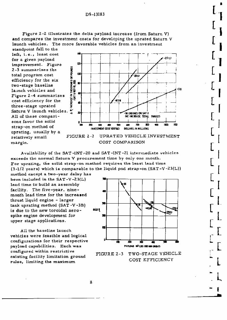
Figure 2-2 i l lus t ra tes the delta payload inc rease (from Saturn V) and compares the investment costs for developing the uprated Saturn V launch vehicles. The more favorable vehicles from an investment standpoint fall to the left, i . e . , least cost for a given payload improvement. F igure 2-3 summarizes the total program cost efficiency for the six two-stage baseline launch vehicles and Figure 2-4 summar izes cost efficiency for the three-s tage uprated Saturn V launch vehicles All of these compar i sons favor the solid strap-on method of uprating, usually by a relatively small margin.
1
I a? •a
140 1 r 1 '
120-
/ / \
too 1
1 1
/ » S 1 / \
BU'
/ * / 1 ^ ^
Ov
40 — - —-/-«s
•^ 1
I
iff
0
" • " " ^ M ENGINES ON SAT Y M C INCREASE TOTAL THRUST)
i 1 1 1 1
-it
m OT 300 400 SOD
INVESTMENT COST IDOTK) too no u
DOLLARS IN MILLIONS no 1000 WO
FIGURE 2-2 UPRATED VEHICLE INVESTMENT COST COMPARISON
Availability of the SAT-INT-20 and SAT-INT-21 intermediate vehicles exceeds the normal Saturn V procurement time by only one month. F o r uprating, the solid s t r ap -on method r equ i re s the least lead t ime (3-1/2 years) which is comparable to the liquid pod s t rap-on (SAT-V-23(L)) method except a two-year delay has been included in the SAT-V-23(L,) » lead time to build an assembly facility. The f ive-year, n ine - m
month lead time for the increased thrust liquid engine - l a rge r tank uprating method (SAT -V-3B) is due to the new toroidal a e r o - t u \ apike engine development for at upper stage applications.
n
AH the baseline launch vehicles were feasible and logical configurations for their respect ive payload capabil i t ies. Each was configured within res t r ic t ive existing facility limitation ground ru les , limiting the maximum
no
V \
M0 200 100
-«SH
400 40 HO
PAYLOAD mLtSOOONMOHITt
FIGURE 2-3 TWO-STAGE VEHICLE COST EFFICIENCY
3

D5-13183
m pay load a c h i e v e d to 579, 000 pounds lfay
t o 100 n a u t i c a l m i l e E a r t h o rb i t (SAT-V-23(L) ) . T h e l iquid pod m
s t r a p - o n concep t , with u p r a t e d 1 U a F - l s and advanced eng ines in the «o-second s t age ( S A T - V - 2 4 ( D ) , a c h i e v e d pay loads to 960, 000 pounds «o to 100 nau t i ca l m i l e E a r t h orb i t when s t age and t o t a l veh i c l e l eng th a» r e s t r i c t i o n s w e r e r e l a x e d .
MTV.
r V -asiv
^ -au
no m PAYIOAC HP US IRHRI.UIJMTIWNSFBITltA.JI
m
FIGURE 2-4 T H R E E - S T A G E VEHICLE COST E F F I C I E N C Y
9
D5-13183
10
4 »
i
D5-13183
3 . 0 GUIDE LINES AND ASSUMPTIONS
T h e fol lowing guide l i n e s , ground r u l e s , and a s s u m p t i o n s w e r e u sed in the s tudy .
3.1 G E N E R A L
a. App l i cab le da ta f r o m p rev ious s t u d i e s w e r e u t i l i zed to the g r e a t e s t ex ten t p o s s i b l e .
b . The b a s e l i n e v e h i c l e s w e r e the AS-516 and the AS-213 aa defined by M S F C . Apollo des ign c r i t e r i a w a s used except w h e r e o t h e r w i s e spec i f i ed or a p p r o v e d by M S F C . M e m o r a n d u m R-P& V E - D I R - 6 5 - 1 4 3 , " S a t u r n V I m p r o v e m e n t S t u d i e s " , da t ed N o v e m b e r 5, 1965, w a s i a s u e d by MSFC to s e r v e a s the r e f e r e n c e documen t for MSFC and c o n t r a c t o r p e r s o n n e l d i r e c t l y involved in the S a t u r n V I m p r o v e m e n t S t u d i e s . M e m o R - P & V E - D I R - 6 5 - 1 4 3 con ta ins a d e s c r i p t i o n and def ini t ion of the p r o j e c t e d l aunch veh ic l e AS-516 to be u s e d a s the b a s e l i n e r e f e r e n c e for the S a t u r n V I m p r o v e m e n t S tud ies . One m i n o r devia t ion to the AS-516 S-IC s t a g e def in i t ion was m a d e with MSFC c o n c u r r e n c e . The r e d e s i g n of t he c e n t e r eng ine c r o s s b e a m s u p p o r t w a s e l i m i n a t e d a s a b a s i c change b e c a u s e of a l a c k of defini t ive d e s i g n d a t a .
C. Al l p r o p u l s i o n da ta used by the s t age c o n t r a c t o r s w e r e a p p r o v e d by M S F C .
d. Both l a u n c h veh ic le and l aunch fac i l i ty mod i f i ca t i ons w e r e c o n s i d e r e d . E x c h a n g e of i n f o r m a t i o n be tween the launch fac i l i ty and launch veh ic le s tudy c o n t r a c t o r s w a s c o o r d i n a t e d wi th MSFC and KSC.
e . T r a j e c t o r y , p rope l l an t d i s t r i b u t i o n , and s t a g e s i z e op t imiza t ion p r o c e d u r e s u s e d w e r e compara 'b le to M S F C m e t h o d s .
f. The n o m i n a l m i s s i o n p ro f i l e s u s e d to s i ze and e s t a b l i s h the b a s e l i n e veh i c l e des ign , to e s t a b l i s h t r a j e c t o r i e s for hea t ing and con t ro l a n a l y s i s i and a s a b a s i s for p e r f o r m a n c e c o m p a r i s o n w e r e :
1, T w o - s t a g e , d i r e c t a s c e n t to 100 nau t i ca l m i l e c i r c u l a r orb i t a l t i t u d e .
2 . T h r e e - s t a g e , with p r e - o r b i t a l igni t ion of the t h i r d s t age to 100 n a u t i c a l m i l e c i r c u l a r pa rk ing orb i t followed by a second bu rn out of o r b i t to 7 2 - h o u r l u n a r in jec t ion . T h i s i s the p lanned Sa tu rn V method .
11

D5-13183-3
Some v e h i c l e s u sed t w o - s t a g e , d i r e c t a s c e n t to a 100 nau t i ca l m i l e c i r c u l a r p a r k i n g orb i t fol lowed by igni t ion of a t h i r d s t a g e and boos t to a 7 2 - h o u r l u n a r t r a n s f e r t r a j e c t o r y .
g. L a u n c h a z i m u t h f rom AMR w a s 70 d e g r e e s m e a s u r e d f r o m nor th to south ove r e a s t and fl ight p r o f i l e s w e r e op t imized in the p i t ch p l ane .
h. Veh ic le he ight , for bo th t w o - and t h r e e - s t a g e v e h i c l e s , w a s l i m i t e d to 410 fee t .
i . P a y l o a d dena i ty w a s he ld a t five pounds pe r cubic foot m a x i m u m for two s t a g e o p e r a t i o n and 11 pounds p e r cub ic foot m a x i m u m for the t h r e e - s t a g e v e h i c l e .
3 . 2 FIRST STAGE
T h i r t y - t h r e e foot d i a m e t e r and 2 . 2 9 p r o p e l l a n t m i x t u r e r a t i o of the ex i s t ing S-IC s t age w e r e to be m a i n t a i n e d .
3 . 3 SECOND STAGE
a. P r o p e l l a n t m i x t u r e r a t i o of 5:1 and 33-foot d i a m e t e r w e r e to be m a i n t a i n e d .
b . M a x i m u m s t a g e leng th for b a s e l i n e s e l e c t i o n w a s l i m i t e d to 1,160 i n c h e s .
3 . 4 THIRD STAGE
a. P r o p e l l a n t m i x t u r e r a t i o of 5:1 and 260- inch d i a m e t e r w e r e to be m a i n t a i n e d .
b . M a x i m u m s tage l eng th equiva len t to 350 ,000 pounds p r o p e l l a n t capac i ty at a m i x t u r e r a t i o of 5:1 (about 16. 5 foot i n c r e a s e ) was to be m a i n t a i n e d .
3 . 5 RESOURCES
a. Where t w o - and t h r e e - s t a g e conf igura t ions of the s a m e b a s i c veh ic le w e r e e x e r c i s e d , the t h r e e - s t a g e conf igura t ion was ana lyzed .
b . U p r a t e d S a t u r n V s t a g e s w e r e to be f a b r i c a t e d by the p r e s e n t c o n t r a c t o r s and cos t da t a for t h e s t a g e s w e r e ob ta ined f r o m the c o n t r a c t o r s .
12
D5-13183
c. The impact of study vehicles on test facil i t ies at MSFCi teat facili t ies at M T F , and launch facil i t ies at KSC were considered with the ass i s tance of those agencies or their designated contrac tors .
d. Two flight tes t s were specified to qualify uprated vehicles.
e. A production p rogram of thir ty operational uprated vehicles to be produced in five yea r s was specified.
f. Uprated vehicles will be considered to be produced at six per year with Saturn IB a companion program at six per year .
g. Intermediate payload vehicles will be considered to be produced at six per year with Saturn V a companion program at six per year .
h. A dynamic test vehicle was required.
3.6 SCHEDULE
A p rogram schedule was required subject to the following res t r ic t ions :
a. The uprated vehicle development program was to be paral le l with the existing Saturn V program and not in terfere with the existing Saturn V del ivery schedule.
b. Vehicle development time to be a minimum, consistent with completion of a thorough test p rog ram.
c. A p rog ram definition phase (PDP) was required prior to beginning uprating vehicle design and development. Ear l i e s t allowed PDP s ta r t was January 1967.
d. Ear l ies t allowed authority to proceed for hardware design and development was Janaury 1968.
3.7 PRICING
It was also required in performing these r e s o u r c e s analyses that the following pricing c r i t e r i a be met:
a. Necessary funds a re available as. requi red .
b . All costs were quoted in 1966 dol lars with no inflationary factor or mid-point es t imate .
c. All costs were based on two-shift, five-day week for manufacturing and one-shift, five-day week for engineering.
13

D5-13183
I N T - 2 0 I N T - 2 1
281.4
323.3
I. U.
J - 2 / F - L
3/1
4 /1
100 N Mi Orb i t Ph - 103 L B S
78
132
F - 1 / J - 2 100 N M i *L " 103 L B S
4 / 3 167
4 / 4 186
4 / 5 L96
5 /3 222
5 /4 246
5 /5 255
FIGURE 4-1 INT VEHICLES
14
D5-13183
4.0 MLV-SAT-1NT-20/-21 LAUNCH VEHICLES
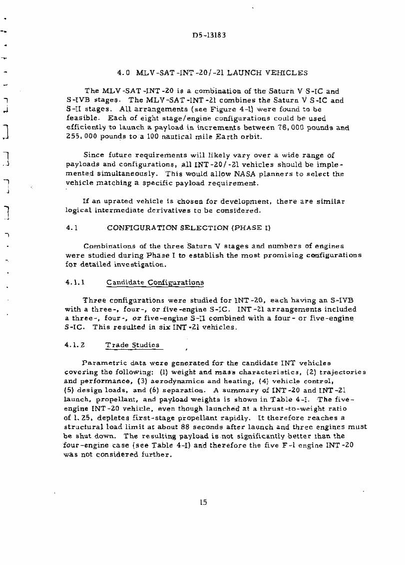
The MLV-SAT-INT-20 is a combination of the Saturn V S-IC and S-IVB stages. The MLV-SAT-INT-21 combines the Saturn V S-IC and S-II s tages . All a r rangements (see F igure 4-1) were found to be feasible. Each of eight stage/engine configurations could be used efficiently to launch a payload in increments between 78, 000 pounds and 255, 000 pounds to a. 100 nautical mile Ear th orbit .
Since future requirements will likely vary over a wide range of payloads and configurations, all INT-2Q/-21 vehicles should be imple mented simultaneously. This would allow NASA planners to select the vehicle matching a specific payload requi rement .
If an uprated vehicle is chosen for development, there a re s imilar logical intermediate derivatives to be considered.
4.1 CONFIGURATION SELECTION (PHASE I)
Combinations of the three Saturn V s tages and numbers of engines were studied during Phase I to establish the most promising configurations for detailed investigation.
4.1.1 Candidate Configurations
Three configurations were studied for INT-20, each having an S-IVB with a t h r e e - , four- , or five-engine S-IC. INT-21 a r rangement s included a t h r e e - , four- , ox five-engine S-II combined with a four - or five-engine S-IC. This resul ted in six INT-21 vehicles .
4 .1.2 Trade Studies — — _ — * . — • — - i — /
P a r a m e t r i c data were generated for the candidate INT vehicles covering the following: (1) weight and m a s s cha rac te r i s t i c s , (2) t ra jec tor ies and performance, (3) aerodynamics and heating, (4) vehicle control, (5) design loads, and (6) separation. A summary of INT-20 and INT -21 launch, propellant, and payload weights is shown in Table 4-1. The five-engine INT-20 vehicle, even though launched at a thrust - to-weight ratio of 1.25, depletes f i r s t - s t age propellant rapidly. It therefore reaches a s t ruc tura l load l imit at about 88 seconds after launch and three engines must be shut down. The result ing payload is not significantly bet ter than the four-engine case (see Table 4-1) and therefore the five F - l engine INT-20 was not considered further.
15
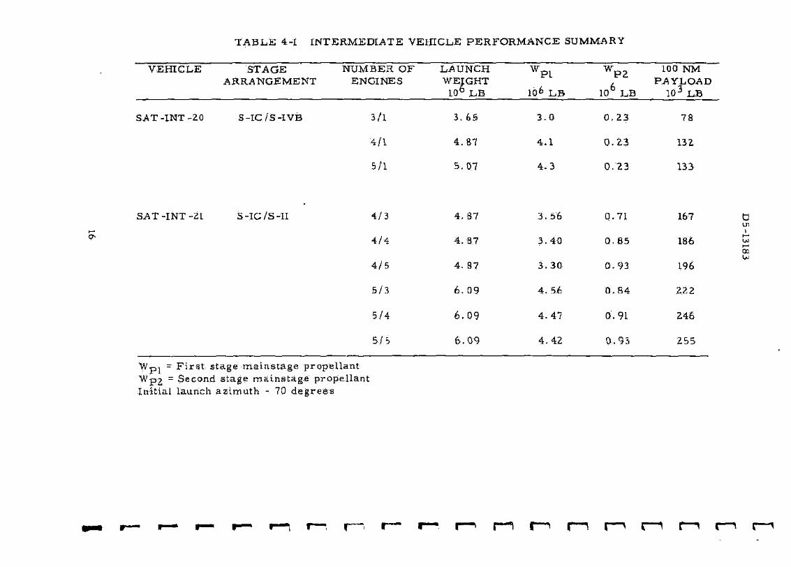
TABLE 4-1 INTERMEDIATE VEHICLE PERFORMANCE
VEHICLE STAGE ARRANGEMENT
NUMBER OF ENGINES
LAUNCH WEIGHT
LO6 LB
W W P1
IG6 LB
SAT -INT -20 S-IC/S-IVB 3/1 3.65 3 . 0
4 / 1 4.87 4 .1
5 /1 5.07 4 - 3
SAT-INT-21 S-IC/S-II 4 / 3 4 . 8 7
4 / 4 4. 87
4 / 5 4. 87
5 /3 6. 09
5 / 4 6 . 0 9
5 / 5 6 . 0 9
3. 56
3. 40
3 .30
4. 56
4 . 4 7
4 . 42
Wp, = F i r s t stage mainstage propellant Wp2 = Second stage mainstage propellant Initial launch azimuth - 70 degrees

D5-13183
at
8
750 - i
an
ts <
1 5 0 -
INT20
air
a IOD-I a:
M-
0 - *
S-1VS/S-M MIEftSTME
1 • # • 1
F t / J - i 3/1 4/1 MSRfcD S/YR 42.3 42.3
U$R&D 1Z/YR17O.5170.5 $/l-B 80-6 496
S-IC BURNTIME 146 212 (3-146) (2-146)
4/1 4/4 4/5 573 5/4 5/5
37.'8 37.8 35-8 35.5 15.5 33.5
168. 2 168. 2 166. 2 165, 9 165. 9 163. 9 431 402 395 337 i l5 314 154 148 143 161 155 150
(2 -146T2 -146J4-14!)(I-146)| t -146)(1-146)
AVAIL
? VBS
AFTER ATP
SINGLE BW
AUVEH
1177*1
SINGLE RID
NOPROO INC U3M
FIGURE 4 -2 I N T - 2 Q / - 2 1 VEHICLE COMPARISON
F o r t he r e m a i n i n g base l ine cand ida t e s (shown on F i g u r e 4 - 2 ) , it w a s n e c e s s a r y to shut down one or m o r e F - l eng ines du r ing f i r s t s tage flight to avoid the p r e s e n t 4 . 68 g longi tudina l a c c e l e r a t i o n l i m i t . The t i m e of shutdown and n u m b e r of engines shut down a r e shown wi th the f i r s t - s t a g e b u r n t i m e on F i g u r e 4 - 2 .
I N T - 2 0 and INT -21 veh ic le c o s t s w e r e d e r i v e d for six l aunches pe r y e a r for five y e a r s . I t was a s s u m e d that S a t u r n V w a s a l so l aunched at the s a m e r a t e du r ing th i s p e r i o d . Bulk of the n o n - r e c u r r i n g cos t ( see F i g u r e 4-2) is due to the i n c r e a s e in p roduc t i on and launch r a t e s . A p p r o x i m a t e l y 124- m i l l i o n d o l l a r s a r e r e q u i r e d at KSG to build and equip for t he new r a t e . The r e m a i n d e r c o v e r s m o s t l y f a c i l i t i e s , t oo l s , and e q u i p m e n t . Note t h e m a r k e d r e d u c t i o n in R&D cos t for eight p e r y e a r and six p e r y e a r INT p roduc t i on r a t e s . T h e n o n - r e c u r r i n g cos t for i m p l e m e n t i n g al l conf igura t ions s i m u l t a n e o u s l y i s e s t i m a t e d to be 13 mi l l i on d o l l a r s (eight p e r c e n t ) m o r e than the l o w e s t - c o s t s ingle a r r a n g e m e n t a t 12 p e r y e a r .
17
D5-13183
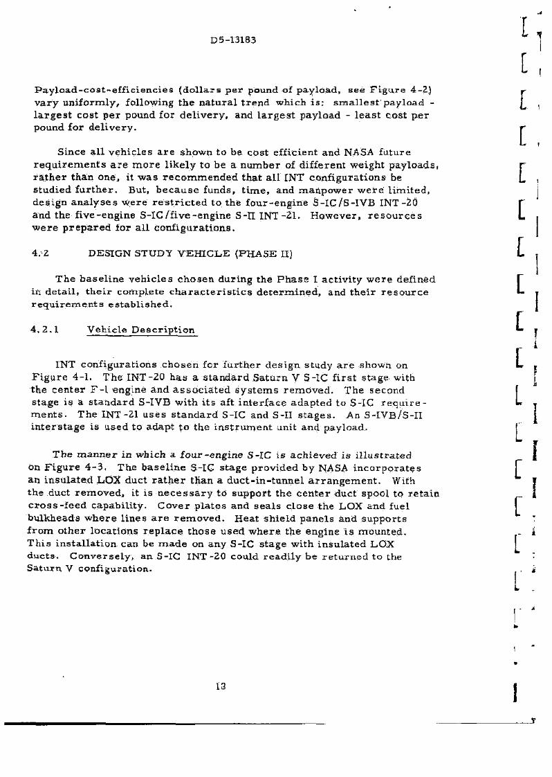
P a y l o a d - c o s t - e f f i c i e n c i e s ( d o l l a r s p e r pound of pay load , s ee F i g u r e 4-2) v a r y u n i f o r m l y , following the n a t u r a l t r e n d wh ich i s : s m a l l e s t pay load -l a r g e s t cos t p e r pound for d e l i v e r y , and l a r g e s t pay load - l e a s t cos t p e r pound for d e l i v e r y .
Since a l l v e h i c l e s a r e shown to be cos t eff icient and NASA fu ture r e q u i r e m e n t s a r e m o r e l i ke ly to be a n u m b e r of d i f ferent weight p a y l o a d s , r a t h e r than one , it w a s r e c o m m e n d e d tha t a l l INT conf igu ra t ions be s tud ied f a r t h e r . But, b e c a u s e funds, t i m e , and m a n p o w e r w e r e l i m i t e d , de s ign a n a l y s e s w e r e r e s t r i c t e d to the f o u r - e n g i n e S - I C / S - I V B INT-20 and the f ive -eng ine S - I C / f i v e - e n g i n e S-II INT - 2 1 . H o w e v e r , r e s o u r c e s w e r e p r e p a r e d for a l l c o n f i g u r a t i o n s .
4 . 2 DESIGN STUDY V E H I C L E (PHASE II)
The b a s e l i n e v e h i c l e s c h o s e n du r ing the P h a s e I ac t i v i t y w e r e defined in de t a i l , t h e i r comple t e c h a r a c t e r i s t i c s d e t e r m i n e d , and t h e i r r e s o u r c e r e q u i r e m e n t s e s t a b l i s h e d .
4 . 2 . 1 Veh ic l e D e s c r i p t i o n
INT conf igura t ions c h o s e n for f u r t h e r des ign s tudy a r e shown on F i g u r e 4 - 1 . The INT-20 h a s a s t a n d a r d Sa tu rn V S-IC f i r s t s tage with the c e n t e r F - l engine and a s s o c i a t e d s y s t e m s r e m o v e d . The second s tage i s a s t a n d a r d S-IVB wi th i t s aft i n t e r f ace adap ted to S-IC r e q u i r e m e n t s . The INT-21 u s e s s t a n d a r d S-IC and S-II s t a g e s . An S- IVB/S- I I i n t e r s t a g e i s used to adapt t o the i n s t r u m e n t unit and payload .
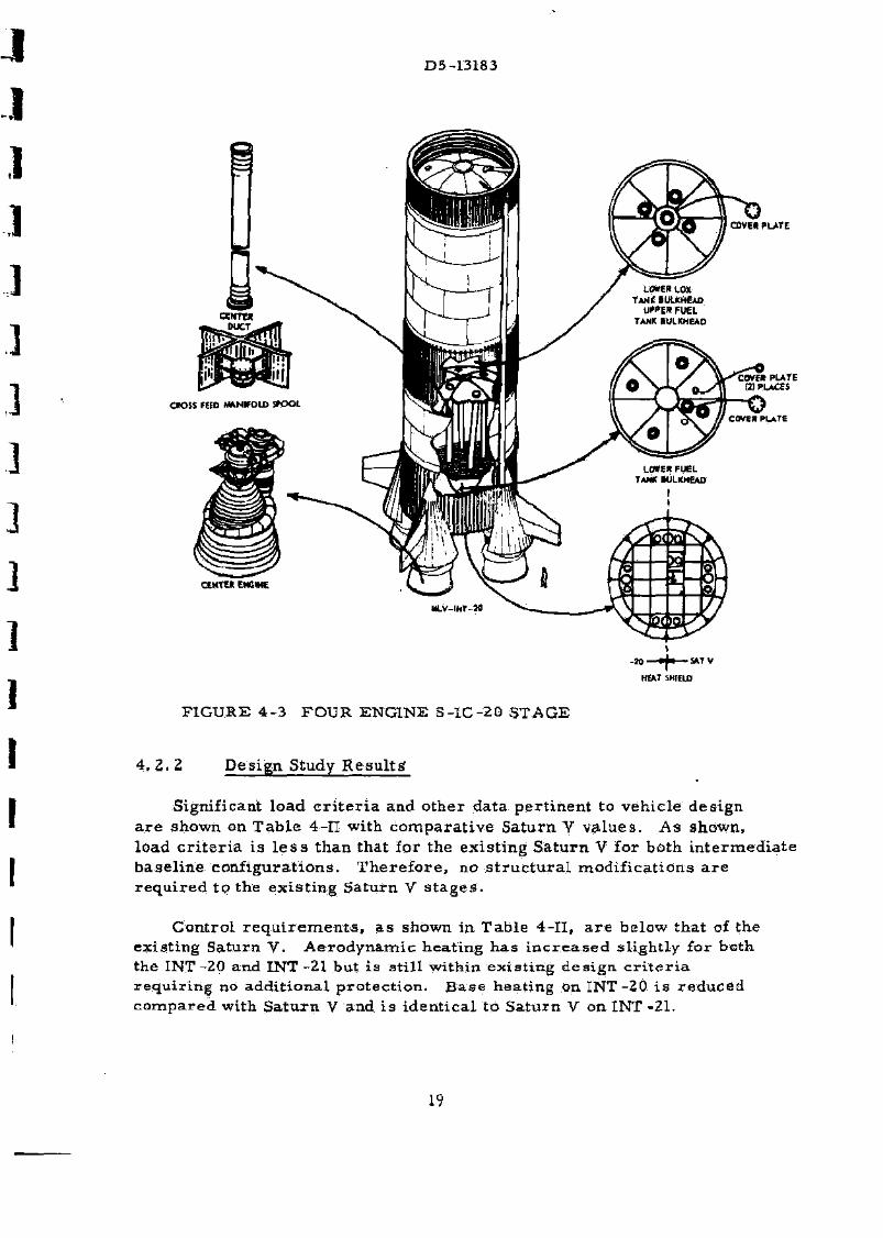
T h e m a n n e r in which a f o u r - e n g i n e S-IC i s a c h i e v e d i s i l l u s t r a t e d on F i g u r e 4 - 3 . The b a s e l i n e S-IC s t a g e p r o v i d e d b y NASA i n c o r p o r a t e s an i n s u l a t e d LOX duct r a t h e r tKan a d u c t - i n - t u n n e l a r r a n g e m e n t . With the duct r e m o v e d , it i s n e c e s s a r y to suppor t the c e n t e r duct spool to r e t a i n c r o s s - f e e d capab i l i ty . C o v e r p l a t e s and s e a l s c l o s e the LOX and fuel bu lkheads w h e r e l i nes a r e r e m o v e d . Hea t sh ie ld p a n e l s and s u p p o r t s f r o m o t h e r l oca t i ons r e p l a c e t hose u s e d w h e r e the engine i s moun ted . T h i s i n s t a l l a t i o n can be m a d e on any S-IC s t age wi th i n su l a t ed LOX d u c t s . C o n v e r s e l y , an S-IC I N T - 2 0 could r e a d i l y be r e t u r n e d to the S a t u r n V conf igura t ion .
13
D5-13183
COVEK PLATE
COVE* PLATE HIPLACES
CIOSS fEiD M*N*OU> V O O t
CENTER ENGME
COVES PLATE
-20 » p SAT V
HEAT SKIEID
FIGURE 4-3 FOUR ENGINE S-IC-20 STAGE
4 .2 .2 Design Study Results?
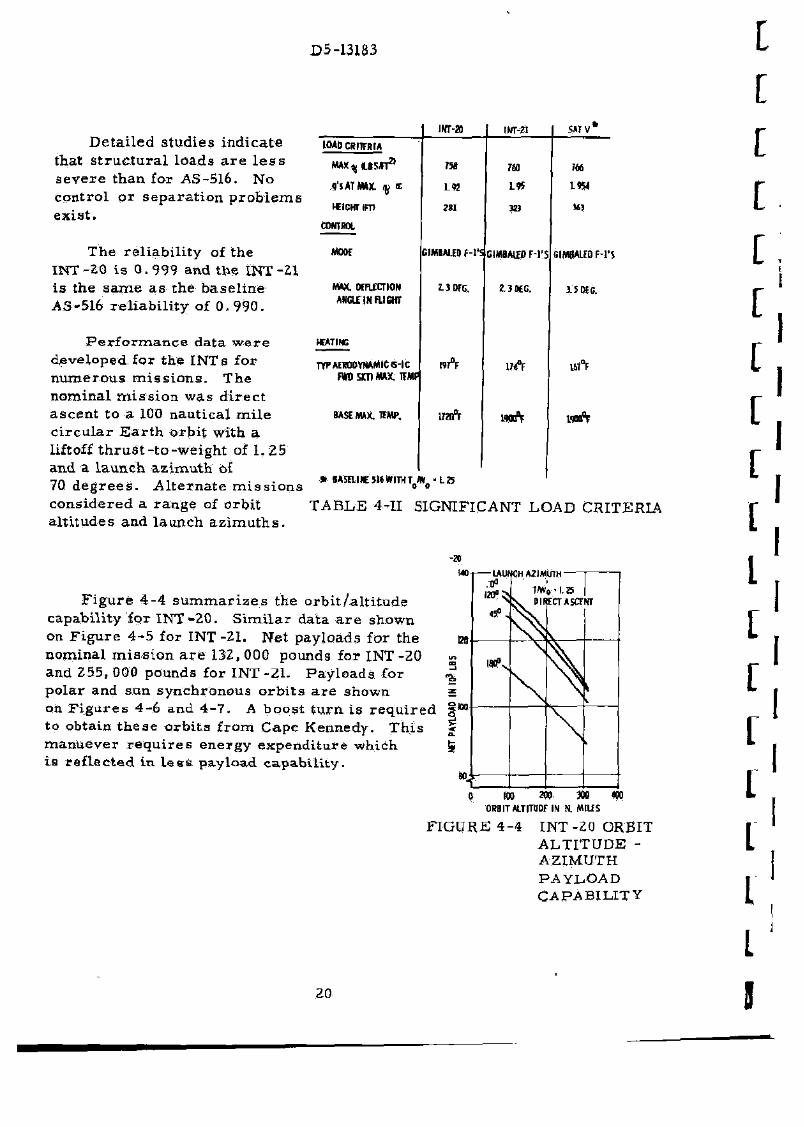
Significant load c r i t e r i a and other data pertinent to vehicle design are shown on Table 4-II with comparative Saturn V values. As shown, load cr i te r ia is l e s s than that for the existing Saturn V for both intermediate baseline configurations. Therefore, no s t ruc tura l modifications are required to the existing Saturn V s tages .
Control r equ i rements , as shown in Table 4-11, a re below that of the existing Saturn V. Aerodynamic heating has increased slightly for both the INT-20 and INT-21 but is still within existing design c r i t e r i a requiring no additional protection. Base heating on INT-20 is reduced compared with Saturn V and is identical to Saturn V on INT -21.
19
D5-13183
Detailed studies indicate that s t ruc tura l loads a re l e s s severe than for AS-516. No control or separation problems exist .
The reliabili ty of the INT-20 is 0. 999 and the INT-21 is the same as the baseline AS-516 rel iabil i ty of 0. 990.
Per formance data were developed for the INT a for numerous miss ions . The nominal miss ion was direct ascent to a 100 nautical mi le c i rcular Ear th orbit with a liftoff thrust- to-weight of 1. 25 and a launch azimuth of 70 degrees . Alternate miss ions considered a range of orbit altitudes and launch azimuths .
iHT-a IW-2I SMV1
LOAD CRITFRIA
MAXqflJS^T21 ua HO m
9'SATMW. ty £ L « L « t«H
WIGHT i m ?8I m 343
ctwrot.
MOM GIMBAliD f-l'S GIMBALEB F-1'S GIMBAliD F-l'S
MAX. WFtfCTION ANGLE INFLIGHT
Z.3BFG. £3 KG. 1SMG.
HEATING
TYP AERODYNAMIC S-|C W0 SOI MAX. IHU
1«°F lift 16I°F
BASE MAX, TEMP.
at i l o i I U ; cliUfiruT >
iraft mft waft
TABLE 4-II SIGNIFICANT LOAD CRITERIA
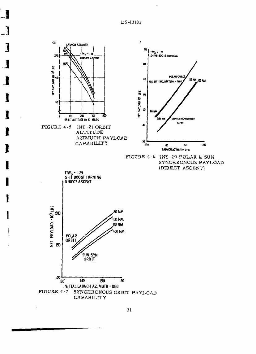
Figure 4-4 summar izes the orbit /al t i tude capability for INT-20. Similar data a re shown on Figure 4-5 for INT-21. Net payloads for the nominal miss ion a r e 132, 000 pounds for INT-20 and 255,000 pounds for INT-21. Payloads for polar and sun synchronous orbi ts a re shown on Figures 4-6 and 4-7. A boost turn is required to obtain these orbits from Cape Kennedy. This manuever requ i res energy expenditure which is reflected in l e s s payload capability.
TO m 3W 4W ORBIT ALTITUDF IN N. Ml l fS
FIGURE 4-4 INT-20 ORBIT ALTITUDE -AZIMUTH PAYLOAD CAPABILITY
20
J
D5-13183
-a LAUNCH AZIMUTH
T*„ - | .25.
W
to
70
»
so
T«„-I.B S-IVB BOOST TURNING
POLAR ORBITy
100 200 300 * » ORBITALTIIUOEIHN. MILES
$
F I G U R E 4 - 5 I N T - 2 1 ORBIT A L T I T U D E AZIMUTH PAYLOAD CAPABILITY
m
3D
(ORBIT IHCLIWTKW-*!/ ttNV»NM
JO MM
100 N* X SUN SYNCHRONOUS ORBIT
i3o i« iM m LAUNCH AZIMUTH DFG
ca
—> ZOO
< o
150
irx
T/W0 - f. 25 S-l I BOO ST TURNING DIRECT ASCENT
F I G U R E 4 -6 I N T - 2 0 P O L A R Sr SUN SYNCHRONOUS PAYLOAD (DIRECT ASCENT)
POLAR ORBIT
.80 NM
100 NM .80 NM
100 NM
SUN SYN ORBIT
130 140 150 160 INITIAL LAUNCH AZIMUTH -DEC
FIGURE 4-7 SYNCHRONOUS ORBIT PAYLOAD CAPABILITY
21
D5-13183
4 . 2 . 3 R e s o u r c e s
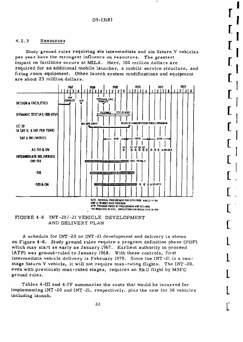
Study g round r u l e s r e q u i r i n g s ix i n t e r m e d i a t e and six Sa tu rn V v e h i c l e s pe r y e a r have the s t r o n g e s t inf luence on r e s o u r c e s . The g r e a t e s t i m p a c t on f ac i l i t i e s o c c u r s a t MILA. H e r e , 100 m i l l i o n d o l l a r s a r e r e q u i r e d for an add i t iona l m o b i l e l a u n c h e r , a mob i l e s e r v i c e s t r u c t u r e , and f i r ing r o o m equ ipmen t . O t h e r l aunch s y s t e m modi f i ca t ions and equipment a r e about 23 m i l l i o n d o l l a r s .
2 I 3
1968 i-U-U
I9W
J_U 3 1970
2 3 A 1971
2 3 1
1772
Z 3 4
DFSIGN& FACILITIES
DYNAMIC TEST (AS-500-DTV)
LC-39
16 SAT V, 6 INT PER YEAR)
SAT V DELIVERIES
AS-515 A ON
INTERMEDIATE DELIVERIES
-INT-516
-518
-520 ft ON
PDP CQMPUTt M ?
7 I
AS?{MiU TFSTAIMSfC
H E WW CONST I I SEAOY ffLAUNOf SIYHRIMIXS WWBAMI
7
WYR • -itwvR
I I 517 iW 5? W3
M H O
HltlimillliMUlTiiimimnTi HMlO IRM -OTOtoi
i i i i imi i iBniMiimi lnl i i i l l l l l lUTrnre
irffl
0 0 0 *ONMYR
mnmap 4 9 0 & ON WYK
NOTE: MATERIAL PROCUREMfNT TOR H(Y« PROD. AN0LC-D-*) AMD LC-» MDBS PACE PROGRAM 8JYS PftOGRAM PAGED BY PROCUREMENT AND M5S KWp •AS RtOUESTED BY KSC. PRODUCTION CAN «ACH1?IYR IN W0
FIGURE 4-8 I-NT-20/-21 VEHICLE D E V E L O P M E N T AND DELIVERY P L A N
A schedu le for INT-20 o r INT-21 d e v e l o p m e n t and d e l i v e r y i s shown on F igure . 4 - 8 . Study g round r u l e s r e q u i r e a p r o g r a m defini t ion phase (PDP) which m a y s t a r t a s e a r l y a s J a n u a r y 1967. E a r l i e s t au tho r i ty to. p r o c e e d (ATP) was g r o u n d - r u l e d to J a n u a r y 1968. With t h e s e c o n t r o l s , f i r s t i n t e r m e d i a t e veh ic le d e l i v e r y is F e b r u a r y 1970. Since the INT -21 i s a t w o -s tage Sa tu rn V v e h i c l e , it w i l l not r e q u i r e m a n - r a t i n g f l igh t s . The I N T - 2 0 , even with p r e v i o u s l y m a n - r a t e d s t a g e s , r e q u i r e s an R&D flight by MSFC ground r u l e s .
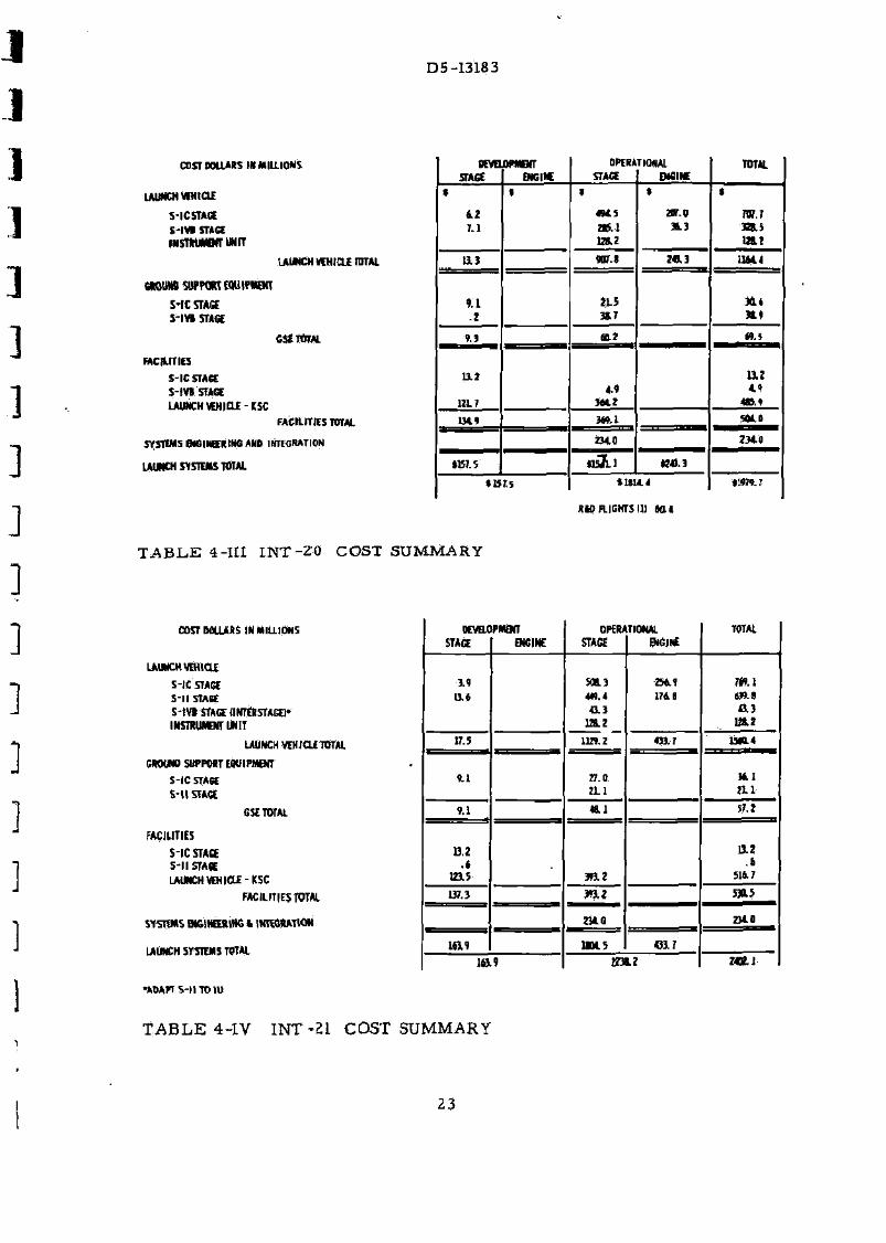
T a b l e s 4-III and 4-IV s u m m a r i z e the c o s t s tha t would be i n c u r r e d for i m p l e m e n t i n g I N T - 2 0 and I N T - 2 1 , r e s p e c t i v e l y , p lus the cost for 30 v e h i c l e s including l aunch .
22
D5-13183
COST DOLLARS IN MILLIONS PEWLOHMENT 5TAGC ENGINE
OPERATIONAL STAGE ENGINE
TOTAL
LAUNCH W H I C H
S-IC STAGE S-IVB STAGE INSTMJMENT UNIT
*
42 7.1
1 1
494.5
tO.1
• 207.0
1
rar.7 32B.5
m i LAUNCH W H I C H TOTAL 13.3 407.) 743.3 1164,4
GROUND SUPPORT EQUIPMENT
S-IC STAGE
S- IV I STAGE
9.1 .2
Hi 3J.7
CS£ TOTAL 9.3
112
12LT
a.2 M.S
FACILITIES
S-IC STAGE
S - I W STAGE
LAUNCH WHICLE-KSC
9.3
112
12LT 4.4
3(42
a : 4.4
FACILITIES TOTAL 134.4 3W-1
234,0
tisT-i
w o
SYSTEMS ENGINEERING AND 1NTFG«ATION
3W-1
234,0
tisT-i
Z34.0
LAUNCH SYSTEMS TOTAL IB7.5
3W-1
234,0
tisT-i « & 3
115 J, 5 *U14.4
RID RIGHTS III 40,4
i i m . 7
T A B L E 4-III I N T - 2 0 COST SUMMARY
COST DOLLARS IN MILLIONS
LAUNCH W H I C H
S-IC STAGE S- l l STAGE S - I V I STAGE (INTERSTAGE]* INSTRUMENT UNIT
LAUNCH WHJCLETOTAL
GROUND SUPPORT EQUIPMENT
S-IC STAGE S- l l STAGE
GSETOTAL
FACILITIES
S-IC STAGE 5-11 STAGE LAUNCH WHICLE-KSC
FACILITIES TOTAL
SYSTEMS ENGINEERING t INTEGRATION
LAUNCH SYSTEMS TOTAL
•ADAPT S - l l TO IU
oevac STAGE
IPMENT ENGINE
OPEN STAGE
TIONAL ENGINE
TOTAL
1 4 13.*
508.3 444.4 43.3
128.2
2549 174 8
7*9.1 634-1 43.3
L&2
IT. 5 1129.2 433.7 1540.4
341
2L1 4.1 27.0
2L1
1540.4
341
2L1
9.1 48,1 57.2
13.2 .«
1215 393.2
13.2 .4
S14 7
137.3 393.2 5345
234.0 Z3A0
1&9 U04.5 4317
Z3A0
10 9 ZO L2 KB.I
T A B L E 4-IV I N T - 2 1 COST SUMMARY
23

D5-13183
ion
m
i «
20B
AlASaiKVEHIOfS
v -»
-1
I»UF-I ; (UttK -MUM
-Z1ISF-I
"" +& M UF-l (D40K
—-^
-SMOO 01UF-U7! «DK| •titmo
100 zoo 300
PAYlQMI-K?LISraiNMOIttiT
FIGURE 4-9 INT VEHICLE COST EFFICIENCY COMPARISON
Figure 4-9 summar izes the payload cost efficiency of the eight INT vehicles (solid lines) not including R&tD flights. The dotted lines a re vehicles similar to INT-20 and INT -21 but using the ML.V-SAT-V-3B stages (see Section 5.0 of th is document). These data demonstrate that INT vehicles could be derived from any of the uprated configurations studied. The s t rap-on sys tems , in addition to f i rs t and third or first and second stage combinations, can also be assembled with zero , two, or four boos t -ass is t uni ts .
I I
[ c: c:
r L
L"
24
-J
J D5-13183
25

D5-13183
r 396 DIA PAYLOAD-367,400 lbs.
I.U. (3rd Stags)
i J
MS-IVB A L 3 = 16.5 ft.
(2 StogeM II TMR = 5 = 1 Wp 3 = 350 K lbs.
I x 400 K lbs. 110' Toroidal Eng.
410 f t
MS-1 fiL2= 15,5 f t .
TMR = 5 * r
Wp = 1.293 M lbs.
7 x 400 K lbs. II0"D. Tori da I Eng'
STA 4604.5
4439
4248
260 DIA PAYLOAD 160,600 lbs.
3879 • ' 3843
: 3721
3277 3 l6a5
C' \ 3075 (Engine Gimbal) 7 \ 2 o 7 7 •
A L| =20 f t
W
MS-IC
= 4.99 M lbs. ' ' {100 N.M.),
= 4.80 M lbs. (LOR)
= 5.6 M lbs. CAPACITY
5 * 1800 K lbs. F- | Engines
i i
2941 •
2810
2072
2024 1938 • 1835 (Engine Gimbal) 1804 • 1781 1641
• SEPARATION
1005
695
365
100 (Engine Gimbal)
STA -115.5
FIGURE 5-1 MLV-SAT-V-3B BASELINE LAUNCH VEHICLE "I
26
D5-13183
5 . 0 M L V - S A T - V - 3 E LAUNCH VEHICLES
The S A T - V - 3 B ( see F i g u r e 5-1) i s a S a t u r n V with a l l s t a g e s lengthened and the t h r u s t of e ach s t a g e i n c r e a s e d .
The v e h i c l e , as def ined in the t r a d e s tudy ac t iv i ty and s tud ied in de ta i l in the P h a s e II ac t iv i ty , i s a feas ib le conf igura t ion and a Logical cand ida t e to p r o v i d e pay loads in e x c e s s of t h o s e c u r r e n t l y ava i lab le wi th the S a t u r n V v e h i c l e .
5. 1 CONFIGURATION S E L E C T I O N (PHASE I)
T r a d e s t u d i e s w e r e d i r e c t e d t o w a r d s d e r i v i n g suff ic ient data to a l low MSFC to d e t e r m i n e the b e s t c o m p r o m i s e M S - I I - 3 B s t a g e t h r u s t l eve l which s a t i s f i ed r e q u i r e m e n t s for both the S A T - V - 3 B t h r e e - s t a g e veh ic l e and the M L V - S A T - I N T - 1 7 t w o - s t a g e v e h i c l e . The I N T - 1 7 u s e s the S A T - V - 3 B u p p e r s t a g e s (MS-I I /MS-IVB) a s a g round launch veh ic l e , and w a s s tud ied c o n c u r r e n t l y by N o r t h A m e r i c a n Avia t ion u n d e r s e p a r a t e c o n t r a c t .
5 . 1 . 1 C a n d i d a t e Conf igura t ions
M S - I C - 3 B t h r u s t was fixed a t five 1.8 mi l l i on -pound F - l engines for a l l c o n f i g u r a t i o n s . The second s t age i s an M S - I I - 3 B us ing f r o m four to s e v e n a d v a n c e d eng ines with 300, 000 to 700, 000 pounds of t h r u s t . The t h r e e - s t a g e v e h i c l e s have an M S - I V B - 3 B a s the t h i r d s t a g e us ing a s ing le engine of t he s a m e type and t h r u s t level as for the second s t a g e . M a x i m u m veh ic l e l eng th w a s 410 fee t .
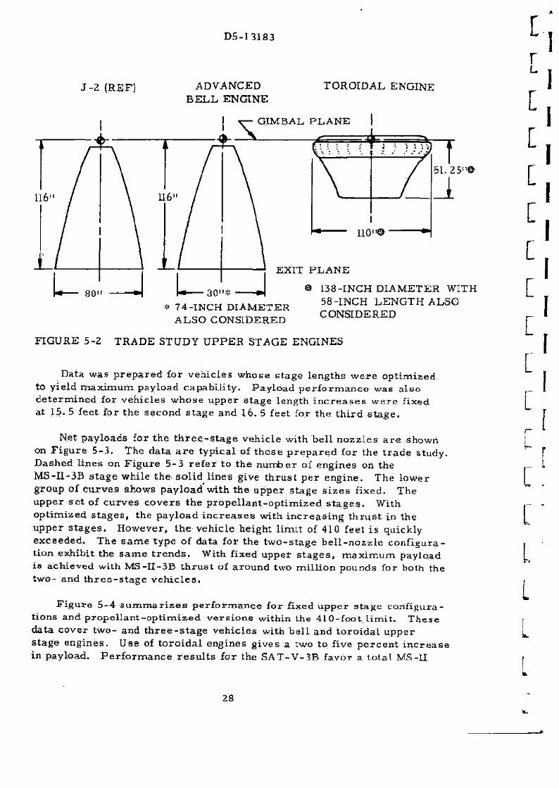
Upper s t a g e p r o p u l s i o n c o n s i d e r e d two advanced engine c o n c e p t s , a t o r i o d a l aer .ospike engine and an advanced be l l engine ( see F i g u r e 5-2) .
The L O X / L H g a e r o s p i k e engine h a s a t o r o i d a l c o m b u s t o r and t r u n c a t e d a e r o d y n a m i c sp ike a n n u l a r n o z z l e . Th i s d e s i g n r e s u l t s in a 6 4 - i n c h r e d u c t i o n in engine leng th . The o t h e r engine c o n s i d e r e d was a h i g h - p r e s s u r e L O X / L H 2 concep t with a bel l n o z z l e . B e l l nozz le engine length , f r o m g imba l po in t to noz&le ex i t p l a n e , was ma in t a ined a t 116 i n c h e s b e c a u s e of u p p e r s t a g e i n t e r s t a g e c l e a r a n c e r e q u i r e m e n t s .
5. 1. 2 T r a d e S tud ie s
P a r a m e t r i c da ta deve loped for the S A T - V - 3 B two- and t h r e e - s t a g e veh ic les i nc luded : (1) weight and m a s s c h a r a c t e r i s t i c s , (2) t r a j e c t o r i e s and p e r f o r m a n c e , (3) a e r o d y n a m i c s and hea t ing , (4) des ign loads , and (5) s e p a r a t i o n . T r a d e s w e r e a l s o m a d e for the two types of advanced engines o p e r a t i n g ove r a r a n g e of t h r u s t l e v e l s .
27
D5-13183
J - 2 (REF) ADVANCED B E L L ENGINE
51.25"©
U 30"* J 74-INCH DIAMETER A L S O CONSIDERED
EXIT P L A N E
138-INCH DIAMETER WITH 58-INCH L E N G T H ALSO CONSIDERED
FIGURE 5-2 TRADE STUDY U P P E R STAGE ENGINES
Data was p r e p a r e d for veh i c l e s whose s t age lengths w e r e op t imized to yield m a x i m u m payload capab i l i t y . Pay load p e r f o r m a n c e was a l so d e t e r m i n e d for veh i c l e s w h o s e upper s t a g e length i n c r e a s e s w e r e fixed a t 15. 5 feet for the s e c o n d s t a g e and 16. 5 feet for the t h i r d s t a g e .
Net pay loads for the t h r e e - s t a g e veh ic le with bel l n o z z l e s a r e shown on F i g u r e 5 - 3 . The data a r e t yp ica l of t h o s e p r e p a r e d for the t r a d e s tudy . D a s h e d l ines on F i g u r e 5-3 r e f e r to t he n u m b e r of engines on the MS- I I -3B s t a g e whi le the s o l i d l ines give t h r u s t p e r engine . The lower g roup of c u r v e s shows pay load with t he u p p e r s t age s i z e s f ixed. The u p p e r s e t of c u r v e s c o v e r s t he p r o p e l l a n t - o p t i m i z e d s t a g e s . With op t imized s t a g e s , the pay load i n c r e a s e s with i n c r e a s i n g t h r u s t in the u p p e r s t a g e s . However , t he veh ic le height l i m i t of 410 feet i s quickly exceeded . The s a m e type of data for the t w o - s t a g e b e l l - n o z z l e c o n f i g u r a t ion exhibi t the s a m e t r e n d s . With fixed upper s t a g e s , m a x i m u m payload i s achieved with MS- I I -3B t h r u s t of a round two mi l l ion pounds for both the t w o - and t h r e e - s t a g e v e h i c l e s .
F i g u r e 5-4 S u m m a r i z e s p e r f o r m a n c e for fixed u p p e r s t a g e conf igura t ions and p r o p e l l a n t - o p t i m i z e d v e r s i o n s within the 410-fpot. l i m i t . T h e s e data cove r two- and t h r e e - s t a g e veh ic les with b e l l and t o r o i d a l u p p e r s t age e n g i n e s . Use of t o r o i d a l engines g i v e s a two to five p e r c e n t i n c r e a s e in payload. P e r f o r m a n c e r e s u l t s for the S A T - V - 3 B favor a t o t a l MS-U
r L
L L
L
[
[
[
[
L [ r L
[
[
l. L 1
28

D5-13I83
. ' / < " "
OPTIMIZED mers
S-UTHRUST (VACUO™ LBS
FIGURE 5-3 TRADE STUDY PERFORMANCE DATA
thrust of around two million pounds using 400, 000 to 500, 000 pounds of thrust per engine. Seven 300, 000 pound thrust second stage engines show a 2. 6 percent inc rease over five 400, 000 pound thrust engines. The lower thrus t engines exhibit bet ter performance because engine length was held constant. To decrease engine thrust , the nozzle throat a rea was decreased thereby increas ing engine area rat io and thus specific impulse. Higher mixture ratio (6:1) in upper stages showed a smal l payioad improvement as indicated.
m on m
£3K>
I* M
SO
3»
These t rade study data, those prepared on MLV-SAT-INT-17 and the i r respect ive t rade study r e s o u r c e analysis were compared by NASA/MSFC
ffflfl OPTIMIZED WITH «0ffETVFHFCL£ UNOHLIMIT
r ~ f FIXED UPPER STAOS
i * aw
J.H,
7««K
//JaLi-o
MR-41 SHOOK
m I * SDK
«7i«0K
rv\
(WT-LTOrT)
7
JW-fcl
mm »L,-0
ALj-lS'
Wft1"*
4(HK
r l H
i n
• i *
i e :
<5XM HW-flPTl
»S •IB
BO
•m
KLL TOROIDAl BfU TOROIDAL
FIGURE 5-4 TRADE STUDY VEHICLE PAYLOAD COMPARISON
29
D5-13183
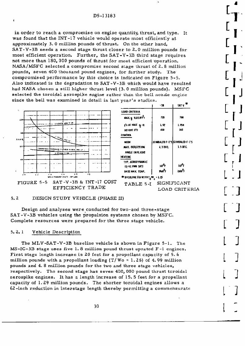
i n o r d e r to r e a c h a c o m p r o m i s e on engine quantity, t h r u s t , and t y p e . It was found tha t the INT-17 veh ic l e would o p e r a t e m o s t eff icient ly a t a p p r o x i m a t e l y 3 . 0 m i l l i on pounds of t h r u s t . On the o the r hand , S A T - V - 3 B n e e d s a second s t a g e t h r u s t c l o s e r to 2 . 0 mi l l ion pounds for m o s t efficient o p e r a t i o n . F a r t h e r , t h e S A T - V - 3 B t h i r d s t age r e q u i r e s not m o r e than 180, 000 pounds of t h r u s t for m o s t efficient o p e r a t i o n . NASA/MSFC s e l e c t e d a c o m p r o m i s e second s t a g e t h r u s t of 2 . 8 m i l l i on pounds , s e v e n 400 thousand pound eng ines , for f u r t h e r s tudy . The c o m p r o m i s e d p e r f o r m a n c e by this choice is ind ica ted on F i g u r e 5 - 5 . Also ind ica ted i s the d e g r a d a t i o n to S A T - V - 3 B which would have r e s u l t e d had NASA chosen a s t i l l h i g h e r t h r u s t Level {3. 0 mi l l ion pounds ) . M S F C s e l e c t e d the t o r o i d a l a e r o s p i k e engine r a t h e r than the be l l nozzle engine s ince the be l l w a s e x a m i n e d in de ta i l in l a s t y e a r ' s s t u d i e s .
i i « V ... ,
• • • - — i i «
—V _ t ' U f C I LOU* ' ! •
\ V , . _ ... . — wa
\ V , . _ ... . — wa
... _ " " < ^ ^ V , ,
... _
(IW >:ou*i*rr» FOR***! J -sfflCE IT- (B ft, 1-iT-bT _
-" " " ' >:ou*i*rr»
; - * T * t ; V-IB -" " " '
-" " " '
iffl „. _ _...-. --- . — — - " •
! * -' * A * U l - l t THHUir IVACl • 10* L f l l
-38 SATV
LOAD OHTERIA
MAX,fl ( IBSFI2) 735 ?»
g'i AT MAX ^ (c LW 1.9M
HEIGHT m i 410 363
CONTROL
MOW GIMBALEDF-l'S GIMBALED f - l ' S
MAX. KRECTION 4.3 DEC U O E G .
ANOf IN R I C H !
HTATINC
TYP. AERODYNAMIC
IS-IC nw am
BASE MAX. TEMP.
167°F lift
FIGURE 5-5 S A T - V - 3 B & INT-17 COST E F F I C I E N C Y TRADE
* BASELINE JW WITH TJW o o
T A B L E 5-1
• L Z 5
SIGNIFICANT LOAD CRITERIA
5 . 2 DESIGN STUDY VEHICLE {PHASE II)
Des ign and a n a l y s e s w e r e conducted for two-and t h r e e - s t a g e S A T - V - 3 B v e h i c l e s us ing the p r o p u l s i o n s y s t e m s c h o s e n by M S F C . Comple t e r e s o u r c e s w e r e p r e p a r e d for the t h r e e s t a g e v e h i c l e .
5. 2 . 1 Vehic le D e s c r i p t i o n
The M L V - S A T - V - 3 B b a s e l i n e veh ic le i s shown in F i g u r e 5 - 1 . The M S - I C - 3 B s t a g e u s e s five 1. 8 mi l l ion pound t h r u s t u p r a t e d F - l e n g i n e s . F i r s t s t age length i n c r e a s e i s 20 feet for a p r o p e l l a n t c a p a c i t y of 5. 6 mi l l ion pounds with a p r o p e l l a n t loading (T /Wo = 1.25) of 4. 99 mi l l i on pounds and 4. 8 mi l l ion pounds for the two and t h r e e s t a g e v e h i c l e s , r e s p e c t i v e l y . The second s t a g e has seven 400, 000 pound t h r u s t t o r o i d a l a e r o s p i k e e n g i n e s . I t has a l eng th i n c r e a s e of 15. 5 feet for a p r o p e l l a n t capac i ty of 1.29 m i l l i o n p o u n d s . The s h o r t e r t o r o i d a l engines a l l o w s a 62- inch r e d u c t i o n in i n t e r s t a g e length t h e r e b y p e r m i t t i n g a c o m m e n s u r a t e
30
D5-13183
tankage i n c r e a s e . The t h i r d s t age (for t h r e e s t a g e app l i ca t ion ) u s e s a s i n g l e 400, 000 pound t h r u s t t o r o i d a l a e r o s p i k e eng ine , a 16. 5 foot l eng th i n c r e a s e for a p r o p e l l a n t c a p a c i t y of 350, 000 pounds of p r o p e l l a n t .
5 . 2 . 2 D e s i g n Study R e s u l t s
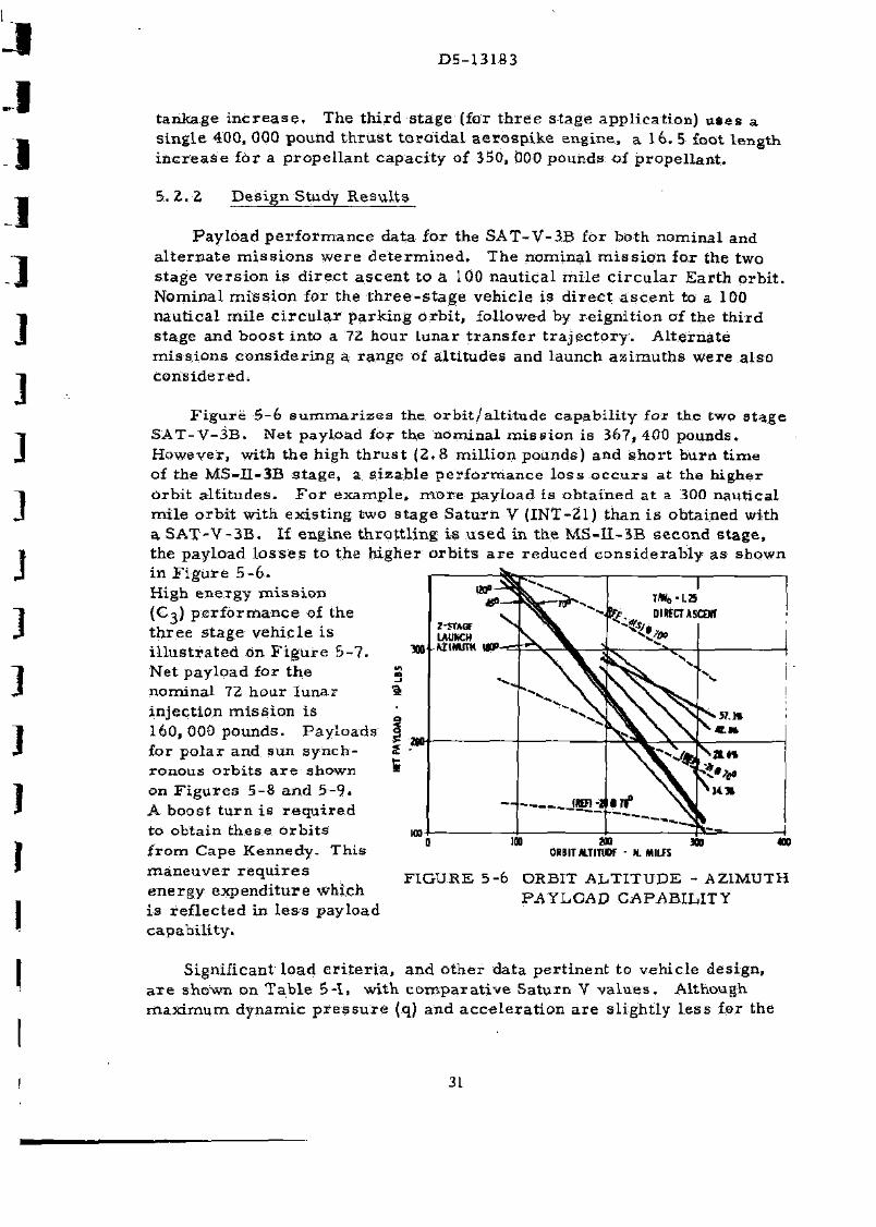
P a y l o a d p e r f o r m a n c e data for the S A T - V - 3 B for both n o m i n a l and a l t e r n a t e m i s s i o n s w e r e d e t e r m i n e d . The n o m i n a l m i s s i o n for the two s t age v e r s i o n i s d i r e c t a s c e n t to a 100 nau t i ca l m i l e c i r c u l a r E a r t h o rb i t . Nomina l m i s s i o n for the t h r e e - s t a g e veh ic le is d i r e c t a s c e n t to a 100 nau t i ca l m i l e c i r c u l a r p a r k i n g o r b i t , fol lowed by r e i g n i t i o n of the t h i r d s tage and b o o s t in to a 72 hour l u n a r t r a n s f e r t r a j e c t o r y . A l t e r n a t e m i s s i o n s c o n s i d e r i n g a, r a n g e of a l t i t udes and launch a z i m u t h s w e r e a l so c o n s i d e r e d .
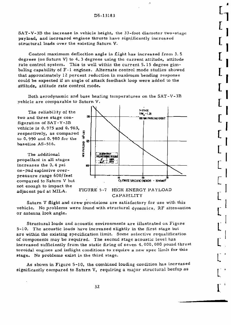
F i g u r e 5-6 s u m m a r i z e s the o r b i t / a l t i t u d e c a p a b i l i t y for the two s t a g e S A T - V - 3 B . Net payload for the n o m i n a l m i s s i o n is 367, 400 pounds . However , with t he high t h r u s t (2 . 8 m i l l i on pounds) and s h o r t bu rn t i m e of the M S - I I - 3 B s t a g e , a s i z a b l e p e r f o r m a n c e l o s s o c c u r s a t the h i g h e r o rb i t a l t i t u d e s . F o r e x a m p l e , m o r e pay load is ob ta ined a t a 300 nau t i ca l mi l e o r b i t with ex i s t i ng two s t a g e S a t u r n V (INT-21) than i s obta ined with a S A T - V - 3 B . If engine t h r o t t l i n g i s u s e d in the M S - I I - 3 B s e c o n d s t a g e , the pay load l o s s e s to the h ighe r o r b i t s a r e r e d u c e d c o n s i d e r a b l y as shown in F i g u r e 5-6-High e n e r g y m i s s i o n (C-a) p e r f o r m a n c e of the t h r e e s t age veh ic l e is i l l u s t r a t e d on F i g u r e 5 - 7 . Net pay load for t he n o m i n a l 72 hour l u n a r in jec t ion m i s s i o n i s 160, 000 pounds . P a y l o a d s for p o l a r and sun s y n c h ronous o r b i t s a r e shown on F i g u r e s 5-8 and 5 - 9 . A boost t u r n i s r e q u i r e d to obta in t h e s e o r b i t s f r o m Cape Kennedy . Th i s m a n e u v e r r e q u i r e s e n e r g y e x p e n d i t u r e which i s r e f l e c t ed in l e s s pay load capab i l i t y .
ORBIT AlTITWf - N. MILfS
F I G U R E 5-6 ORBIT A L T I T U D E - AZIMUTH PAYLOAD CAPABILITY
Signif icant load c r i t e r i a , and o t h e r data p e r t i n e n t to veh ic le des ign, a r e shown on T a b l e 5-1 , wi th c o m p a r a t i v e S a t u r n V v a l u e s . Although m a x i m u m d y n a m i c p r e s s u r e (q) and a c c e l e r a t i o n a r e s l igh t ly l e s s for the
31
D5-13183
S A T - V - 3 B the i n c r e a s e in veh ic le he ight , the 33-foot d i a m e t e r t w o - s t a g e pay load , and i n c r e a s e d eng ines t h r u s t s h a v e s ign i f ican t ly i n c r e a s e d s t r u c t u r a l loads ove r t he ex i s t i ng S a t u r n V.
C o n t r o l m a x i m u m def lec t ion angle in flight h a s i n c r e a s e d f r o m 3. 5 d e g r e e s (on S a t u r n V) to 4 . 3 d e g r e e s us ing the c u r r e n t a t t i t u d e , a t t i t ude r a t e c o n t r o l s y s t e m . Th i s i s wel l within the c u r r e n t 5. 15 d e g r e e g i m -ba l ing capab i l i ty of F - l e n g i n e s . A l t e r n a t e c o n t r o l m o d e s tud ie s showed t h a t a p p r o x i m a t e l y 12 p e r c e n t r e d u c t i o n in m a x i m u m bend ing r e s p o n s e could be expec ted if an ang le of a t t ack feedback loop w e r e added to t he a t t i t u d e , a t t i tude r a t e c o n t r o l m o d e .
Both a e r o d y n a m i c and base hea t ing t e m p e r a t u r e s on the S A T - V - 3 B veh ic le a r e c o m p a r a b l e to S a t u r n V.
The r e l i ab i l i t y of the two and t h r e e s t a g e c o n f igura t ion of S A T - V - 3 B v e h i c l e i s 0. 975 and 0. 965 , r e s p e c t i v e l y , as compared . to 0. 990 and 0. 980 for the b a s e l i n e AS-516 .
The add i t iona l p r o p e l l a n t in a l l s t a g e s i n c r e a s e s the 0. 4 p s i o n - p a d explos ive o v e r p r e s s u r e r a n g e 600 / f ee t c o m p a r e d to S a t u r n V but not enough to i m p a c t the ad jacen t pad a t MILA.
C3(TWICI SPECIFIC WRCY) - KmhKp
FIGURE 5-7 HIGH ENERGY PAYLOAD CAPABILITY
S a t u r n V flight and c r e w p r o v i s i o n s a r e s a t i s f a c t o r y for use with this v e h i c l e . No p r o b l e m s w e r e found wi th s t r u c t u r a l d y n a m i c s , R F a t t enua t ion o r an tenna look a n g l e .
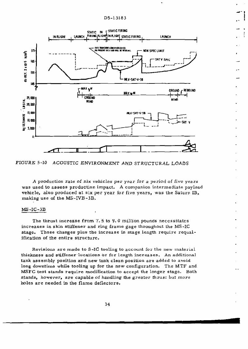
S t r u c t u r a l loads and a c o u s t i c e n v i r o n m e n t s a r e i l l u s t r a t e d on F i g u r e 5 -10 , T h e a c o u s t i c loads have i n c r e a s e d s l igh t ly in the f i r s t s t age but a r e wi thin the ex i s t ing spec i f i ca t ion l i m i t . Some s e l e c t i v e r equa l i f i c a t i on of componen ts m a y be r e q u i r e d . The second s t a g e a c o u s t i c l eve l has i n c r e a s e d sufficiently f r o m the s t a t i c f i r i ng of s e v e n 4, 000, 000 pound t h r u s t t o r o i d a l engines and inf l ight condi t ions to r e q u i r e a new spec l i m i t for th is s t a g e . No p r o b l e m s e x i s t in the th i rd s t a g e .
As shown in F i g u r e 5 -10 , the combined loading cond i t ion has i n c r e a s e d s ign i f ican t ly c o m p a r e d to S a t u r n V, r e q u i r i n g a m a j o r s t r u c t u r a l beefup as
32

D5-13183
130 ! « 150
LAUNCKAZIMI/m DECS
FIGURE 5-8 T W O - S T A G E POLAR & SUN SYNCHRONOUS ORBIT PAYLOAD CAPABILITY
i« m LAUNCH AZIMUTH - OtGS
FIGURE 5-9 T H R E E - S T A G E POLAR St SUN SYNCHRONOUS ORBIT PAYLOAD CAPABILITY
as shown in F i g u r e 5 - 1 1 . P e r c e n t a g e i n c r e a s e s in d r y weights of e ach S A T - V - 3 B s t a g e a r e a l so tabula ted in F i g u r e 5 - 1 1 .
5. 3 RESOURCES
I n c r e a s e s in the length and t h r u s t of t he S A T - V - 3 B - s t a g e s c o m p a r e d to S a t u r n V i m p a c t production,- t e s t , t r a n s p o r t a t i o n and launch f a c i l i t i e s . U p r a t e d F - 1 eng ine and new t o r o i d a l u p p e r s tage engine d e v e l o p m e n t s a r e the m o s t cos t ly i t e m s r e q u i r e d . Ex i s t i ng fac i l i t i es wi l l be emp loyed to m a n u f a c t u r e and t e s t the M L V - S A T - V - 3 B . T h e s e f ac i l i t i e s a r e to be u s e d on a n o n - i n t e r f e r e n c e b a s i s with n o r m a l S a t u r n V p roduc t ion s c h e d u l e s , The p r e s e n t s t a g e and I. U. v e n d o r s w e r e a s s u m e d to be c o n t r a c t o r s for the modif ied v e h i c l e c o m p o n e n t s .
A dynamic t e s t veh ic le , s t r u c t u r a l t e s t c o m p o n e n t s , and two m a n -r a t i n g R&D fl ights a r e r e q u i r e d . Re loca t ion of work p l a t f o r m s and i n c r e a s e in height is r e q u i r e d a t the MSFC Dynamic T e s t Stand to handle the new conf igura t ion . T h e f i r s t s t age of the dynamic t e s t veh ic le will be r e f u r b i shed a f t e r t e s t and used as a flight s t a g e . The second s t a g e of the dynamic t e s t v e h i c l e will have undergone s t r u c t u r a l s t a t i c t e s t p r i o r to -D t e s t i ng .
33
D5-13183
175
145
u: 155
l«
STATIC IN rStATfCFIRING
, INFLIGHT , LAUNCH FIRWCAICHP IB FLIGHT STATIC FIRING.
h H—-h •[• -ir H -h LAUNCH
ON nt«M w VUDMU m •MUW, NfWSPFC LIMIT
SATVSWC E3ATVSWC
J-
MLV-SAT-V-3B
-MAX4.K GROUW r WBOUND
FIGURE 5-10 ACOUSTIC ENVIRONMENT AND STRUCTURAL LOADS
A p roduc t i on r a t e of s i x v e h i c l e s p e r y e a r for a p e r i o d of five y e a r s was u s e d to a s s e s s p r o d u c t i o n i m p a c t . A companion i n t e r m e d i a t e payload veh ic le , a l s o p r o d u c e d a t s i x p e r y e a r for five y e a r s , was t he Sa turn IB, making u s e of the M S - I V B - 3 B .
M S - I C - 3 B
The t h r u s t i n c r e a s e f r o m 7 . 5 to 9- 0 m i l l i on pounds n e c e s s i t a t e s i n c r e a s e s in sk in s t i f f ene r and r i n g f r a m e gage throughout the MS-IC s t a g e . T h e s e changes p lus the i n c r e a s e in s t a g e length r e q u i r e r e q u a l -i f icat ion of t he e n t i r e s t r u c t u r e .
Rev i s ions a r e m a d e t o S-IC tool ing to accoun t for the new m a t e r i a l t h i c k n e s s and s t i f fener l oca t i ons or for l eng th i n c r e a s e s . An addi t iona l t ank a s s e m b l y pos i t i on and new tank c l e a n p o s i t i o n a r e added to avoid long downt ime while tool ing up for the new conf igura t ion . The M T F and MSFC t e s t s t ands r e q u i r e modi f ica t ion to a c c e p t the longer s t a g e . Both s t a n d s , howeve r , a r e c a p a b l e of handl ing t he g r e a t e r t h r u s t but m o r e holes a r e n e e d e d in the f l a m e d e f l e c t o r s .
34

COMMON BLKD INCREASED RADIUS
THRUST STRUCTURE NEW DESIGN 66'
INTERSTAGE 69% > STRENGTH
FORWARD SKIRT 77% > STRENGTH
AFT SKIRT 86% > STRENGTH
NEW TOROIDAL ENGINE
FORWARD SKIRT 142% > STRENGTH
LOX TANK ADDITIONAL FRAMES NEW FEED LINES
INTERSTAGE 60% > STRENGTH
LH2 TANK 44% > STRENGTH
NEW FEED LINES
NEW THRUST STR
7 NEW TO
ONE ADDITIONAL HELIUM BOTTLE
DRY WEIGHT INCREASE MS-1C-3B- 14.2% MS-ll-3B-35.6% MS-IVB-3B-22.5%
FIGURE 5-L1 SAT-V-4(S)B VEHICLE IMPACT
INTERTANK 41% > STRENGTH
THRUST S 35% > ST
D5-13183
T iming Of the M S - I C - 3 B p roduc t i on i s paced by upper s t a g e r e q u i r e m e n t s ; t h e r e f o r e . A u t h o r i t y to P r o c e e d is not r e q u i r e d unt i l 26 mon ths af ter s t a r t of the upper s t a g e p r o g r a m s . With this t i m i n g , the f i r s t f l ight a r t i c l e will be d e l i v e r e d t o MI3-.A 3. 5 y e a r s a f te r f i r s t s t age A T P .
MS-H-3B
The s t r u c t u r e and p r o p u l s i o n s y s t e m changes to th i s s t a g e w i l l n e c e s s i t a t e s t a t i c and d y n a m i c s t r u c t u r a l t e s t s and a " b a t t l e s h i p " t e s t deve lopment p r o g r a m . To m e e t the r e q u i r e d de l i ve ry da te of the d y n a m i c t e s t s t age , p roduc t i on of t he s t a n d a r d S-II would be a c c e l e r a t e d , s t a r t i n g with S - I I -18 . Two fl ight t e s t s t a g e s a r e inc luded in the d e v e l o p m e n t p h a s e .
S t anda rd t r a n s p o r t e q u i p m e n t i s g e n e r a l l y c o m p a t i b l e with the &1S-II-3B, a l though l eng then ing of s t a g e t r a n s p o r t e r s would b e n e c e s s a r y , as well as m i n o r mod i f i ca t i ons such a s r e l o c a t i o n of tie downs oh t h e P o i n t B a r r o w , Bo th Type I and Type II t r a n s p o r t e r s c a n hand le the added weight , excep t t ha t t i r e l o a d s m a y be e x c e s s i v e on the Type I I .
De l ive ry of the d y n a m i c t e s t s t a g e , n ine m o n t h s p r i o r to the f i r s t f l ight s t a g e , d e t e r m i n e s t h e point a t which p roduc t i on of the s t a n d a r d S-II would be p h a s e d out to a l low p h a s e - i n of new tool ing for the M S - H - 3 B . The s t r u c t u r e and p r o p u l s i o n s y s t e m r e v i s i o n s r e q u i r e modi f ica t ion of s t a n d a r d tools or d e s i g n of new t o o l s . Tool ing m a i n l y affected i s tha t for m a n u f a c t u r e of t h e LH-, t a n k , f o r w a r d and aft s k i r t s , i n t e r s t a g e , LOX tank ex tens ion and new t h r u s t s t r u c t u r e .
The Sea l B e a c h fac i l i ty r e q u i r e s s o m e mod i f i ca t i ons , inc luding m i n o r bui lding ex tens ions and r e v i s e d a s s e m b l y s e q u e n c e s . New fac i l i t i e s a r e not n e c e s s a r y , but s t a g e a s s e m b l y and buildup tools will be modi f ied . Handling equ ipment a t a l t f a c i l i t i e s wi l l be modif ied for the i n c r e a s e d s t age weight . Modif ica t ion and checkou t of the Sta t ic "Test Tower would be comple t ed in D e c e m b e r 1971 , -the dynamic t e s t s t age sh ipped to MSFC in D e c e m b e r 1971, and t he f i r s t o p e r a t i o n a l flight s t a g e comple t ed in S e p t e m b e r 1973.
MS-lVBj-_3B
Eng inee r ing d e s i g n o r r e d e s i g n effort i s n e e d e d main ly in the s t r u c t u r e and p r o p u l s i o n s y s t e m a r e a s b e c a u s e of the i n c r e a s e d tank vo lume , h ighe r flight loads and the i n s t a l l a t i o n of a new type h igher t h r u s t eng ine . Deve lopmen t a n d qua l i f i ca t i on ef for t i nvo lves a m o d e r a t e a m o u n t of w o r k a s s o c i a t e d with the s a m e v e h i c l e c h a n g e s . A dynamic t e s t s t age will be fu rn i shed for t e s t a t N A S A / M S F C to ver i fy p r e d i c t e d v ib r a t i on m o d e s and f r e q u e n c i e s .
36

D5-13183
To allow for modification to tooling and facilities without interfering with standard stage del iver ies , a t emporary speed-up of the standard stage assembly is planned. No new fabrication technology is proposed nor any new or unique testing procedures . Some expansion and /or modification of facilit ies is required , at the Santa Monica and Huntington Beach plants , and at the Sacramento Test Center .
The increased stage size precludes t ransporta t ion by the Super Guppy and will mean dependence on ocean shipment to the Sacramento test site and to Kennedy Space Cente r . Major modification of the s tage t r anspor t e r is needed because of the added length, and l e s se r modifications to other i tems of handling equipment.
Launch. Faci l i ty and Operation Impact
Changes a t MILA for the SAT-V-3B vehicle a r e p r imar i ly due to inc reased vehicle length. Mobile launcher swing a rms as well as VAB higb and low bays access platforms a r e relocated. A new (taller) mobile serv ice s t ruc tu re is needed since insufficient time is available between last Sa turn V and f irs t MLV-SAT-V-3B to rework the existing MSS.
No changes a r e required in the Saturn V operat ional plan for SAT-V-3B.
Schedule
An MLV-SAT-V3B vehicle development and delivery schedule is shown in F igure 5-12. The vehicle timing is based on almost four yea r s required for upper stage engine development. Upper stage design is paced so that bat t leship stages axe available when P F R T engines a r e ready. Completion of all c r i t ica l stage ground development testing is completed before the f i r s t flight a r t i c l e reaches MILA in September of 1973.
Cost
A cost summary for the SAT-V-3B is shown in Table 5-II*
37

D5-I3183
I M-KtnuHCflMenmin t m t - t s r u a i a M u n t ucaUHmicnn c o n s t > im»-t ro« cowvn
— cmioLi-imiiuBMnMUM M M « H . wi u n a umcswr nsrm«FitfTH.iBir.
FIGURE 5-12 S A T - V - 3 B V E H I C L E D E V E L O P M E N T AND DELIVERY PLAN
COST - D O L L A R S I N MILLIONS
LAUNCH VEHICLE S-IC 3 t»ge S-II S tage S-IVB S tage I n s t r u m e n t Uni t
LAUNCH VEHICLE T O T A L
GROUND S U P P O R T E Q U I P M E N T
S-IC S tage S-II S tage S-IVB S tage
OSE T O T A L
F A C I L I T I E S
T o r o i d a l Eng ine a S- IC S tage S-II S t a g s S- IVB S tage L a u n c h V e h i c l e - K5C L a u n c h Veh ic l e - O t h e r
F A C I L I T I E S T O T A L
SYSTEMS ENGINEERING AND I N T E G R A T I O N
LAUNCH SYSTEMS T O T A L
D E V E L O P M E N T O P E R A T I O N A L T O T A L STAGE ENGINE STAGE ENGINE
7 0 . 0 123 .0 5 9 6 . 3 4 3 9 . 7 1214.0 165.7 336, Z 551.1 6 8 6 . 9 1 7 7 4 . ; 9 7 . 8 6 2 . 9 3 6 2 . 4
130.7 114.4 6 4 2 . 4
130.7
3 3 3 . 5 5 2 2 . 1 1640. 5 1241.0 3761. 3
10. Q £1.9 31.9 2B.1 6 4 . 8 9 2 . 9 3 3 . 7 4 8 . 5 8 2 . 2
71.8 ' 135 .2 2 0 7 . 0
3 9 , 2 39 .2 13 .3 13. 3 21.7 21.7 7 . 2 5 .4 12.6
81 .7 721 .8 BG3.5 4 . a 4. e
128.7 3 9 . 2 7 2 7 . 2 895 .1
2 . 3 425 .1 425 .1
5 3 6 . 3 561.3 2928.B 1241.0 1097.6 41 >9.0 5266 .6
R&D F L I G H T S U l 3Z5.6
T A B L E 5-II S A T - V - 3 B COST SUMMARY
33
0 5 -13183
39
D 5-13183
T 3 9 6 DIA PAYLOAi
493,900 LBS
I.U. i (3rd Stage) J
MS- IVB
LU--1-
(2ndT Stage)1
i_L
A L = IG.5 ft.
WP = 350 K lbs.
I x J -2 MR = 5-1
STA 4 8 0 4 . 5
4 4 3 9
4 2 4 8
2 6 0 " DIA PAYLOAD 188,800 LBS
3955 • 3919 3797
410 f t A L = 0 f t .
MS-II « p 5 = 9 3 0 K lbs.
5 x J - 2 MR = 5 :
r MS-IC
A L = 41.5 ft.
W P j = 6 . 6 4 M lbs.
5 x 1522 K F- [
Four 3 Segment 156" Sol id Racket Motors
Wps= 4 . 4 5 M lbs.
Web Burning Time 100.6 Seconds
Li i
3330.5 3244.5
I
w /\ /\ /\
[ \f \ 3144 (Engine Gimbal)
•v
3017 2885.5
2346
2258 •
2162 (Engine Gimbal)
2062 • 2039 1899
SEPARATION
A" 1360
1098.5 9 9 8 . 5 (Fwd Attach)
788.5
365
116 (A f t A t t ach )
100 (Engine Gimbal)
STA - 115.5
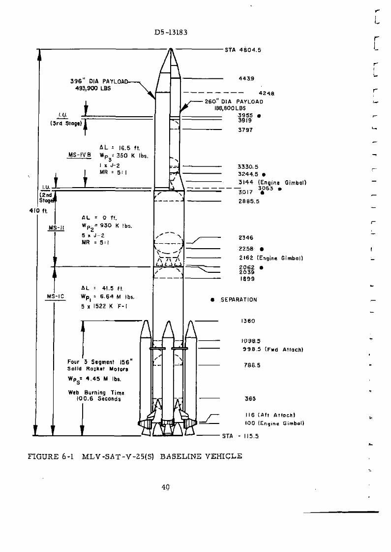
FIGURE 6-1 M L V - S A T - V - 2 5 ( S ) BASELINE VEHICLE
40
D5-13183
6. 0 M L V - S A T - V - 2 5 ( S ) LAUNCH VEHICLE
The Sa tu rn V-25(S) vehic le ( see F i g u r e 6-1) i s a Sa tu rn V wi th l eng thened f i r s t and t h i r d s t a g e s , adapted for a t t a c h m e n t of four 156- inch d i a m e t e r sol id p r o p e l l a n t m o t o r s .
The veh ic le a s defined in the P h a s e I t r a d e study ac t iv i t y and s tudied in de ta i l in the Phas .e II ac t iv i ty i s a f eas ib le conf igura t ion and a log ica l c a n d i da te to p r o v i d e p a y l o a d s in e x c e s s of t h o s e c u r r e n t l y a v a i l a b l e with the Sa turn V veh ic le .
6. 1 CONFIGURATION SELECTION (PHASE I)
By v a r y i n g t he weight and t h r u s t of the 156- inch so l id r o c k e t m o t o r s and the weight of p r o p e l l a n t in t he c o r e s t a g e s , a n u m b e r of r e l a t e d SAT-V-25(S) v e h i c l e s w e r e evolved. Pay load capab i l i ty and vehic le c o s t s w e r e e s t a b l i s h e d for t h e s e veh i c l e s in o r d e r to c h o o s e one a r r a n g e m e n t for m o r e de ta i l ed a n a l y s i s .
6. 1.1 C a n d i d a t e Conf igura t ions
F o r the t r a d e s tudy, both t w o - and t h r e e - s t a g e o p e r a t i o n was c o n s i d e r e d -Vehic le height w a s fixed a t 410 feet for both t w o - and t h r e e - s tage c o n f i g u r a t ions . P r o p u l s i o n and engine type for a l l s t a g e s wag fixed to c o r r e s p o n d to the b a s e l i n e AS-516 veh ic le . Vary ing we igh t s of p r o p e l l a n t and c o r r e s p o n d i n g s t age lengths w e r e s tudied for a l l s t a g e s . F o u r 156- inch sol id p r o p e l l a n t r o c k e t m o t o r s w e r e a t t ached to t he veh ic le for t h r u s t augmen ta t i on . The n u m b e r of s e g m e n t s (and thus sol id p r o p e l l a n t weight) in t he sol id m o t o r s w a s v a r i e d b e t w e e n two and four . Solid m o t o r t h r u s t / t i m e r e s t r a i n t s w e r e specif ied by M S F C . B u r n t i m e s and t h r u s t l eve l s of the v a r i o u s s ized sol id m o t o r s w e r e va r i ed a l s o , within the r e s t r a i n t s , to o p t i m i z e veh ic le liftoff t h r u s t - t o -we igh t .
6 . 1 . 2 T r a d e S t u d i e s
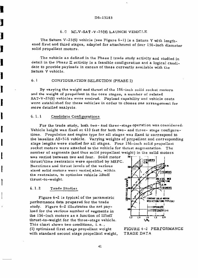
F i g u r e 6-2 i s t y p i c a l of the p a r a m e t r i c p e r f o r m a n c e da t a p r e p a r e d for t he t r a d e study. F i g u r e 6-2 i l l u s t r a t e s the ne t p a y -load for the v a r i o u s n u m b e r of s e g m e n t s in the 156- inch m o t o r s a s a function of liftoff t h r u s t - t o - w e i g h t for the t h r e e - s t a g e veh i c l e . Th i s c h a r t shows two condi t ions , i . e. , (1) o p t i m i z e d f i r s t s t a g e p rope l l an t weight with s t a n d a r d second s t age p r o p e l l a n t weight ,
F IGURE 6-2 P E R F O R M A N C E TRADE DATA
41

D5-13183
and (2) optimized propellant weights for the f i rs t and second stages. The MS-IVB in all cases was sized to maximize payload out of 100 nautical m i l e E a r t h o r b i t to l u n a r in jec t ion . Note tha t t he c u r v e s a r e t he loc i of m a x i m u m pay load resu l t ing , f r o m c o n s i d e r i n g different cons tan t sol id m o t o r web ac t ion t i m e s combined with v a r i o u s c o r e vehic le launch w e i g h t s .
The da ta d e m o n s t r a t e t h a t :
a. P a y l o a d i n c r e a s e s a p p r o x i m a t e l y eight p e r c e n t with each add i t i ona l solid motor segment.
b. A pay load i n c r e a s e of m o r e than two p e r c e n t a c c r u e s by o p t i m i z i n g second s t age length . T y p i c a l o p t i m i z e d S-H s tage length i n c r e a s e s a r e on the o r d e r of an add i t i ona l t en fee t .
c. Signif icant payload i n c r e a s e s a r e a t t r i b u t a b l e to t he s h o r t e r bu rn t i m e solid r o c k e t m o t o r s and the r e s u l t i n g h ighe r va lues for liftoff t h r u s t - t o -weight r a t i o ,
In deve loping t h e s e d a t a , no s t r u c t u r a l pena l t i e s w e r e a s s e s s e d to the cand ida te v e h i c l e s for the liftoff t h r u s t - t o - w e i g h t v a r i a t i o n . When s t r u c t u r a l weight pena l t i e s , a r e c o n s i d e r e d , a s they w e r e in o the r s i m i l a r s t ud i e s , it i s found tha t beyond 1. 6 to 1.8 t h r u s t - t o - w e i g h t , payload i n c r e a s e s a r e not a s l a r g e a s ind ica ted on F i g u r e 6 - 2 .
OPTIMIZED S-l I
Z.M
ira wo no 200 PAYUM0-IB5*I03
F i g u r e 6 -3 c o m p a r e s the pay load cos t eff ic iency of d i f fe ren t so l id m o t o r we igh t s for the op t imized S-I I s tage and s t a n d a r d length S-II s t a g e . The c h a r t i n d i c a t e s tha t S-II s t a g e op t im iza t i on i s not w o r t h w h i l e but tha t l a r g e r sol id m o t o r w e i g h t s c a n s ign i f ican t ly i m p r o v e veh ic le co s t eff iciency, F r o m t h e s e d a t a , and b e c a u s e m i n i m u m sol id m o t o r b u r n t i m e w a s ground ru led a t 100. 6 s e c o n d s , i t w a s r e c o m m e n d e d to MSFC tha t the veh ic le i n d i c a t e d a s " b a s e l i n e " on F i g u r e s 6-2 and 6-3 be c h o s e n for t he next p h a s e of s tudy. MSFC a p p r o v e d t h i s s e l ec t ion .
FIGURE 6-3 COST E F F I C I E N C Y TRADE DATA
42

D5-131S3
6. 2 DESIGN STUDY VEHICLE (PHASE II)
The single SAT-V-25(S) vehicle chosen during the P h a s e I activity was defined in detail , i ts capabilities and charac te r i s t i cs were determined, and i ts r e source requi rements were established.
6.2. 1 Vehicle Description
The MLV-SAT-V-25(S) baseline vehicle is shown in F igure 6 -1 . It ut i l izes four th ree -segment 156-inch s t rap-on solid rocket motors each with 1. 1 million pounds of propellant for thrust augmentation. Each solid motor has a launch thrust of 4. 0 million pounds. They burn regress ive ly so that at burnout thrus t is reduced to about 65 percent of the liftoff value. Each of the solid motors has a liquid injection (N2O4) thrus t vector control system to augment the capability of the gimbaled F - l engines during flight through the max q reg ime . The liquid core stages of SAT V-25(S) a re equipped with standard F - l and J -2 engines. F i r s t stage propellant capacity has been inc reased to 6. 64 million pounds by lengthening the stage 41. 5 feet. The second stage is standard S-II length with a propellant capacity of 930,000 pounds. The third stage (for th ree - s t age applications) is increased in length by 16-1/2 feet and has a propellant capacity of 350,000 pounds.
6. 2. 2 Design Study Resul ts
As noted on Figure 6 - 1 , the SAT-V-25(S) two stage payload capability to 100 nautical mile orbit i s almost 494, 000 pounds and its 72-hour lunar injection th ree - s t age capability i s almost 189, 000 pounds.
Use of this vehicle was also considered for applications where the baseline core vehicle (liquid stages without solids) could be flown by itself or with only two s t rap-on solid motors . The payloads identified for these a l te rna tes a r e shown on Table 6-1.
To further improve payload, a special study was conducted to determine the effect of tai loring the solid motor thrust time t race . For this study, the thrus t was made r eg re s s ive until the vehicle has passed through the maximum dynamic p r e s s u r e reg ime. The thrust level was then made progress ive until solid motor burnout. The payload improvement for the optimum r e g r e s s i v e -progress ive thrust t ime t race over that available witn the baseline vehicle was approximately one percent . This improvement was not considered significant enough tp warrant complicating solid motor design for r eg ress ive -p rogress ive burning.
Significant load c r i t e r i a , and oths r data pert inent to vehicle design, a r e
43.

D5-13183
TABLE 6~I PAYLOAD CAPABILITY
Core Vehicle Without Solid Motors
NET PAYLOAD (LB) TWO-STAGE THREE-STAGE 100 NM Orbit 72-hour Lunar T ra j .
T 0 / W o = 1.25
W p l = 4,343,423 lb 231,466 38 ,475
T 0 / W 0 = 1.18
W P 1 = 4,696,492 lb 239,558 91, 568
Core Vehicle With Two Solid Motors
TQ /WQ = 1.40
W p i = 6,000,000 387,073 147,954
Core Vehicle With Four Solid Motors
T 0 / W Q = 1.734
W p i = 6,640,000 lb 493,900 188,800
44

D5-13183
shown on T a b l e 6-II with c o m p a r a t i v e Sa tu rn V v a l u e s . Although m a x dynamic p r e s s u r e (q) and a c c e l e r a t i o n a r e i n c r e a s e d s l ight ly , the 410 foot v e h i c l e he igh t coupled with the 33-foot d i a m e t e r t w o - s t a g e payload c a u s e the l a r g e s t i m p a c t on s t r u c t u r a l des ign r e q u i r e m e n t s .
C o n t r o l r e q u i r e m e n t s n e c e s s i t a t e add i t i ona l c a p a b i l i t y beyond the p r e s e n t fin and F - l eng ine g imbal ing of the f i r s t s t a g e . The u s e of t he l iquid in jec t ion t h r u s t v e c t o r c o n t r o l on the sol id m o t o r i s r e q u i r e d fo r 26 s e c o n d s n e a r m a x q t i m e of fl ight. A l s o , b e c a u s e the f i r s t s t age i s r o t a t e d 45 d e g r e e s c o m p a r e d to Sa tu rn V, t he fl ight con t ro l s ignal m u s t be modif ied to c o m p e n s a t e for the r o t a t ion.
-»S) SATV
LOAD CRITERIA
MAX f HBSIFT2) s» m ,"S AT MAX 4 C L» LW
WIGHT tfT) no m CONTROL
MODE 5IM6AUD F-1'S GIMBALED F-l'5
A e r o d y n a m i c hea t ing i s s ignif icant ly lower thari t he S a t u r n V- T h e shock wave f r o m the so l id m o t o r n o s e c a p m a y i m p i n g e on t he f i r s t s t age LOX tank and loca l i n su l a t ion m a y be r e q u i r e d . No p r o b l e m s a r e a n t i c i p a t e d a s a r e s u l t of a e r o d y n a m i c hea t i ng .
SOLID MAX.
DEFLECTION ANGLf
SOLID TVC OPERATING I
BATING TYPABRMWUIIIC
I S - K F W SOI MAX TEMP
(MAX TEMP 8ASFI
flft€B
M 5 E . I K Sit WITH T * 0 Q
LnvCOM SOLIDS
L80fTRM(JK)lt N/A
46-71 SEC
ZorfF
MS-IC-B IS) ROTATED 45*
L25
N/A
wnrV
T A B L E 6-II SIGNIFICANT LOAD CRITERIA
T h e base hea t ing e n v i r o n m e n t i s m o r e s e v e r e for the M L V - S A T - V - 2 5(S) than for the S a t u r n V due to the solid m o t o r exhaus t p l u m e s . Heat shield m a t e r i a l s can wi ths t and t he an t i c ipa ted 2 0 8 0 ° F t e m p e r a t u r e s success fu l ly . The aft so l id m o t o r a t t a c h m e n t s k i r t wi l l r e a c h 195Q°F. Insu la t ion p r o t ec t ion h e r e wil l be r e q u i r e d .
The r e l i a b i l i t y of the t w o - and t h r e e - s t a g e con f igu ra t ions of Sa tu rn V-25(S) a r e 0. 986 and 0. 964, r e s p e c t i v e l y , a s c o m p a r e d to 0. 990 and 0. 980 for the b a s e l i n e AS-516 . The lower v a l u e s for r e l i ab i l i ty can b e a t t r i b u t e d to the addi t ion of the s t r a p - o n sol id m o t o r s and to longer f i r s t and t h i r d s t age b u r n t i m e s .
S e p a r a t i o n of the 156- inch S R M ' s f rom the v e h i c l e can be a c c o m p l i s h e d s a t i s f a c t o r i l y u s i n g exp los ive s e p a r a t i o n d e v i c e s and s m a l l solid r o c k e t s for s e p a r a t i o n f o r c e .
The addi t ion of m o r e fuel in the f i r s t s t age and the four so l id m o t o r s i n c r e a s e s the 0. 4 p s i o v e r - p r e s s u r e d i s t a n c e to a va lue g r e a t e r than the d i s t a n c e be tween P a d A and P a d B on Launch C o m p l e x 39- W a i v e r s for
45

D5-13183
this d i s t a n c e wi l l be r e q u i r e d for jo in t u sage o£ t h e s e p a d s when e i t h e r pad con ta ins a fueled c o r e v e h i c l e with the sol id m o t o r s a t t ached .
Sa tu rn V flight and c r e w safe ty p r o v i s i o n s a r e s a t i s f a c t o r y for u s e with this veh i c l e . C o m m u n i c a t i o n s for s o m e s t a t ions wi l l be "b lacked out" due to the exhaus t p l u m e i n t e r f e r e n c e , O t h e r s t a t i o n s , however , wi l l have c l e a r an t enna a c c e s s du r ing t h e s e p e r i o d s and cont inuous c o m m u n i c a t i o n s can be m a i n t a i n e d
S t r u c t u r a l loads and a c o u s t i c env i ronmen t a r e i l l u s t r a t e d in F i g u r e 6 -4 . The des ign l o a d s a r e h i g h e r than t hose for the s t a n d a r d Sa turn V r e q u i r i n g an i n c r e a s e in veh ic le s t r u c t u r a l weight . The p r e s e n t acous t i c speci f ica t ion l i m i t s a r e e x c e e d e d a t s e v e r a l l o c a t i o n s on t he f i r s t s t a g e . Requa l i f i ca t ion of acous t i ca l l y s e n s i t i v e c o m p o n e n t s on this s t a g e wi l l be r e q u i r e d .
Major c o r e vehic le c h a n g e s inc luding the i m p a c t of s t r u c t u r a l load i n c r e a s e s i s s u m m a r i z e d in F i g u r e 6 - 5 . D r y weight i n c r e a s e s a r e a l s o tabula ted .
FIGURE 6-4 ACOUSTIC ENVIRONMENT AND STRUCTURAL LOADS
46

MM MM taatf t itf M mJ Unl L-J L-J L-J U-J
COMMON BLKD INCREASED RADIUS
AFT SKIRT 116% > STRENGTH
58% > STRENGTH INCREASE FORWARD SKIRT 177% > STRENGTH
PROPELLANT TANKS
FORWARD SKIRT 195%) STRENGTH
LH2 TANK 574% > STRENGTH
INTERSTAGE-87% > STRENGTH
LOX TANK ADDITIONAL FRAMES 502% > STRENGTH
-FORWA 89% >
INTERSTAGE -86% > STRENGTH
DRY WEIGHT INCREASE MS-IC-25(S) 31.5% MS-1I-25(S) 8.6% MS-IVB-25(S) 27.4%
TWO ADDITIONAL — ^ HELIUM BOTTLES
INTERTANK 115% > STRENGTH
THRUST STRUCTURE 33% > STRENGTH
FIGURE 6-5 SAT-V-25(S) VEHICLE IMPACT

D5-13183
6. 3 RESOURCES
The p r e s e n t s t age , e n g i n e , and I . U. m a n u f a c t u r e r s w e r e a s s u m e d to be c o n t r a c t o r s for the modif ied veh ic le . A dynamic t e s t v e h i c l e , s t r u c t u r a l t e s t c o m p o n e n t s , and two R&D fl ights for m a n - r a t i n g a r e r e q u i r e d . A new dynamic t e s t s tand will be r e q u i r e d for t e s t of th i s veh ic le s i n c e i t s launch we igh t e x c e e d s p r e s e n t S a t u r n V s tand capab i l i t y . The S-IC s t age of the d y n a m i c t e s t veh i c l e wil l b e r e f u r b i s h e d a f t e r t e s t and u s e d a s a flight a r t i c l e . The 156- inch so l id r o c k e t m o t o r s with t he i r t h r u s t vec to r con t ro l s y s t e m m u s t be deve loped and qual i f ied for th is appl ica t ion
A p roduc t ion r a t e of s i x v e h i c l e s p e r y e a r for a pe r iod of five y e a r s w a s u t i l i zed to a s s e s s the p roduc t i on i m p a c t .
MS-IC-25(S.)
F i r s t s t age length i n c r e a s e coupled with the m o r e s e v e r e s t r u c t u r a l l o a d s r e q u i r e changes in skin gage , s t i f fener spac ing , and f r a m e chord a r e a . T h e s e changes n e c e s s i t a t e r e v i s i o n s in manufac tu r ing too l s , New tools a r e r e q u i r e d for so l id m o t o r a t t a c h m e n t s t r u c t u r e m a n u f a c t u r e . The addi t ion of sol id m o t o r func t ions ( igni t ion, s e p a r a t i o n , i n s t r u m e n t a t i o n ) n e c e s s i t a t e s changes and add i t i ons to f i r s t s t age e l e c t r i c a l cable m a n u fac tu r ing b o a r d s .
The longer , h e a v i e r t a n k s of the MS-IC-25(S) cannot be h y d r o s t a t i c t e s t e d in the p r e s e n t Michoud VAB pos i t i on . A new stand wil l be needed and can be loca ted in a p r e s e n t l y unused pos i t ion in that bui lding. The final a s s e m b l y and tank a s s e m b l y s t a t i ons a l s o m u s t be modif ied for i n c r e a s ed s t a g e length
To i n t r o d u c e the new conf igura t ion , without f ac to ry modif ica t ion downt i m e , an add i t iona l tank a s s e m b l y s ta t ion and m o r e s t o r a g e space m u s t be added in the Michoud f ac to ry .
The two p r e s e n t l y unused s t a g e t e s t p o s i t i o n s m u s t be modif ied to accep t t he longer S-IC s t a g e s . Cab le s will be i n s t a l l e d to the p r e s e n t t e s t c o n t r o l s t a t ions and c o m p u t e r s . S o m e new t e s t equ ipmen t (sol id m o t o r s i m u l a t o r s ) and m i n o r modi f ica t ion of ex i s t ing equipment i s r e q u i r e d .
Modif icat ion of the S-IC t e s t f i r ing s t ands a t M T F and MSFC a r e r e q u i r e d only b e c a u s e of t he i n c r e a s e d s tage length and a s s o c i a t e d p rope l l an t c a p a c i t y .
A m i n o r modif icat ion to the s tage t r a n s p o r t e r c a b l e s and s t e e r i n g p o t e n t i o m e t e r wi l l adap t i t for the new s t age leng th . However , the
48

D5-13183
additional stage weight exceeds the forward (thrust s tructure) ca r r i age capability. Two new wheel dollies must be added to the forward car r iage .
Both shuttle and sea going barges must have their decks strengthened and supports and tie downs relocated for the longer heavier stage.
For the solid rocket motors , a development p rogram of ten firings is assumed. Minor facilities a re required but new tools, jigs and fixtures a r e a major i t em. New tes t and checkout and t ransporta t ion equipment i s also included- Rai l t ransportat ion from manufacturer to KSC is assumed.
MS-II-2 5 (S)
Manufacturing requirements for the MS-II-25(S) stage are defined by the schedule del ivery dates and the stage s t ruc tura l modifications. A separate stage will be manufactured to be utilized for both static s t ruc tures test and for stage dynamic test . Delivery of this s tat ic/dynamic (S/D) stage requi res that the standard S-II production be accelera ted to accumulate sufficient s tages to maintain a constant delivery ra te at one stage every two months.
The revised s t ruc tura l design will requi re modification of the fabr i cation and assembly tools for the forward and aft sk i r t s , LH2 tank walls , in ters tage and aero- fa i r ings . The Seal Beach facilities require a minimum of modifications; the major work required is modification to the s t ructural test tower for the increased test loads. Some handling equipment at Tulsa and Seal Beach will require modification as a resul t of the increased stage weight.
The cur rent S-H program t ranspor t equipment and vehicles a r e compatible with the MS-II-25{S) stage design; no modifications would be required to handle the additional stage weight.
MS-IVB-25(5)
The elongated tank of the MS-IVB required by this vehicle has a significant impact on r e sou rce s . The standard S-IVB facilit ies for manufacturing, assembly, test and checkout will need modification to accommodate this la rger , heavier stage. Additional machine tools and space a re required for the detail pa r t manufacturing. The most significant a rea i s the skin mil ls for machining the tanks. The 24 to 36 month delivery time for these machines make early del ivery of modified stages difficult. The assembly and checkout towers must be reworked to increase their ver t ica l capacity. Welding torches, platforms, and stage interfaces must be relocated and adapted to the new vehicle. A complicated scheduling problem exists to provide t ime to modify
49
D5-13183
the f ac i l i t i e s with m i n i m u m i n t e r f e r e n c e wi th d e l i v e r y of s t a n d a r d s t a g e s . T h i s r e q u i r e s a c c e l e r a t i n g the p roduc t ion r a t e of the s t a n d a r d s t a g e s and s t o r i ng t h e m for d e l i v e r y On t h e i r n o r m a l shipping da t e . T h i s could o v e r load s o m e of the checkou t t o w e r s and r e q u i r e e i the r ex t ens ive o v e r t i m e o r addi t ional f ac i l i t i e s and GSE. The s ta t ic f i r ing a t S a c r a m e n t o r e q u i r e s modifying t he t e s t s tand. A s t r e a m l i n i n g of the t e s t p r o c e d u r e i s r e c o m m e n d ed a s a m e a n s of s ign i f ican t ly reduc ing the c o s t of t h e s e mod i f i ca t i ons . The s t r e a m l i n i n g would p e r m i t mak ing the p o s t - f i r i n g checkout in the t e s t s tand and e l i m i n a t e modifying the v e r t i c a l checkout l a b o r a t o r y cells.-
The t r a n s p o r t i n g equ ipment will r e q u i r e some r e d e s i g n and a l l s h i p m e n t s wi l l be by w a t e r s i n c e t he p r e s e n t Supe r Guppy a i r c r a f t cannot c a r r y the e longated s t a g e .
Launch F a c i l i t y and .Launch O p e r a t i o n s I m p a c t
The i m p a c t of t h i s veh i c l e on t he launch fac i l i ty and Opera t ions w a s s tudied by The Mar t i n Company under s e p a r a t e c o n t r a c t to Kennedy Space C e n t e r . T h i s s tudy ac t iv i t y d e s c r i b e d the m i n i m u m i m p a c t l aunch s e q u e n c e s for th i s v e h i c l e a s shown below.
The modif ied c o r e v e h i c l e wil l be a s s e m b l e d a c c o r d i n g to s t a n d a r d p r o c e d u r e s in the VAB on a modif ied mobi le l a u n c h e r (ML) and wil l subsequen t ly be t r a n s p o r t e d to the pad for a t t a c h m e n t of the sol id r-ocket m o t o r s . C o n c u r r e n t wi th t he c o r e veh ic le a s s e m b l y and checkou t , t he solid r o c k e t m o t o r s (SRM) s e g m e n t s and c l o s u r e a s s e m b l i e s wi l l unde rgo r ece iv ing i n spec t i on , componen t i n s t a l l a t i o n and indiv idual checkou t in a new m o b i l e e r e c t i o n and p r o c e s s i n g s t r u c t u r e (MEPS) at a r e m o t e s i t e . After the l iquid c o r e veh i c l e on the mob i l e l a u n c h e r h a s been s e c u r e d to the launch pad, the M E P S wi th i n s p e c t e d s e g m e n t s and p r e - a s s e m b l y c l o s u r e s for a l l four of the sol id r o c k e t m o t o r s wi l l m o v e to t he l aunch pad and wi l l be m a t e d wi th the m o b i l e l aunche r and ground s t r u c t u r e for t r a n s f e r o p e r a t i o n s of the so l id r o c k e t m o t o r s e g m e n t s ( s ee F i g u r e 6 -6 ) . Two c r a n e s moun ted on the MEPS wi l l be u s e d to lift and a t t a c h the. aft solid r o c k e t m o t o r c l o s u r e (with the p r e - a s s e m b l e d aft a t t a c h m e n t s k i r t ) to the l iquid c o r e . A s s e m b l y of two SRMs wi l l be a c c o m p l i s h e d c o n c u r r e n t l y . The t h r e e c e n t e r s e g m e n t s and the fo rward c l o s u r e wil l then be s t a c k e d on top of each of the aft c l o s u r e s . T h i s p r o c e d u r e wil l be dup l ica ted for a s s e m b l y and mat ing of the r e m a i n i n g two sol id r o c k e t m o t o r s . Af te r a s s e m b l y i s m a d e and a l i g n m e n t of al l four SRMs i s c o m p l e t e d , the M E P S wil l then be t r a n s p o r t e d back to i t s p a r k i n g pos i t ion . F r o m th i s point on, the l aunch o p e r a t i o n s p r o c e e d in a m a n n e r s i m i l a r to those for t he Sa tu rn V veh ic le wit,h the except ion of the added o p e r a t i o n s for i n t e g r a t e d so l id rocke t m o t o r checkout and for so l id r o c k e t m o t o r a r m i n g .
50

D 5 - 1 3 1 8 3
i / - sim ABOUT t
-«*-s I I ELEWIQH
FIGURE 6-6 MOBILE E R E C T I O N AND
PROCESSING STRUCTURE
In t roduc t ion of the 156- inch sol id r o c k e t m o t o r s i n c r e a s e s pad occupancy t i m e f r o m 58 to 70 d a y s . However , e m e r g e n c y t ake -down can be a c c o m p l i s h e d in 39 h o u r s , we l l wi thin t he 72 -hour h u r r i c a n e w a r n i n g t i m e .
The ex i s t i ng v e r t i c a l a s s e m b l y bui lding with the w o r k p l a t f o r m l o ca t ions a l t e r e d c a n b e u t i l i zed .
Modi f i ca t ions a t the launch pad inc lude r e i n f o r c e m e n t of t he mob i l e l a u n c h e r suppor t p i e r s and pad s t r u c t u r e and the p r o v i s i o n of h e a t sh ie lds for pad moun ted equ ipmen t a n d ' s t r u c t u r e , new f lame d e f l e c t o r s and i m p r o v e d f l a m e d e f l e c t o r a n c h o r a g e , f l ame p r o t e c t i o n for f l ame t r e n c h w a l l s , a u x i l i a r y e x h a u s t de f l ec to r sh ie lds and i n c r e a s e d high p r e s s u r e gas and p r o p e l l a n t s t o r a g e c a p a b i l i t i e s . Addi t iona l quant i ty and flow r a t e s of i n d u s t r i a l w a t e r wi l l be r e q u i r e d with i n c r e a s e d pumping capac i ty and upg rad ing of t h e h y d r o m a t i c s y s t e m s . The w a t e r m a i n s s e r v i n g the pad a r e a a r e a d e q u a t e without modi f ica t ion . Ex i s t ing e l e c t r i c a l power and c o m m u n i c a t i o n s a r e s a t i s f ac to ry .
A so l id r o c k e t m o t o r i n e r t c o m p o n e n t s bu i ld ing m u s t be p rov ided . A m o b i l e e r e c t i o n and p r o c e s s i n g s t r u c t u r e (MEPS) m u s t be p rov ided with p a r k i n g pos i t i on a n d addi t ional c r a w l e r t r a n s p o r t e r r o a d way for a c c e s s .
T h e "mobile s e r v i c e s t r u c t u r e (MSS) wi l l r e q u i r e a he ight ex tens ion to a
51

D5-13183
leve l of 396 feet to p e r m i t work p l a t f o r m s to be r a i s e d to the r e q u i r e d s e r v i c e l e v e l s . Th i s wi l l r e q u i r e i n c r e a s e d s t r u c t u r a l r e i n f o r c e m e n t and i n c r e a s e d e l e v a t o r r u n s , T h e c a n t i l e v e r f r a m i n g which s u p p o r t s the p l a t f o r m s in the v i c i n i t y of the s o l i d s m u s t be r e w o r k e d to i n c r e a s e the l a t e r a l c l e a r a n c e - It i s not p o s s i b l e to a c c o m p l i s h t h e s e r e q u i r e d modi f i ca t ions in t he f i v e - m o n t h t i m e span be tween the l a s t S a t u r n V launch and the f i r s t MLV-SAT-V-Z5(S) R&D launch; t h e r e f o r e , a new MSS i n c o r p o r a t i n g the a b o v e changes m u s t be bui l t .
One new and one modi f ied mobi l e l a u n c h e r (ML) a r e r e q u i r e d to sa t i s fy the l aunch r a t e and. p r o g r a m p h a s e - i n r e q u i r e m e n t s for t h i s veh i c l e . The p r i n c i p a l mod i f i ca t ions involve r e loca t i on to h i g h e r l e v e l s of a l l u m b i l i c a l a r m s , sh i e ld ing of the front u m b i l i c a l face , i n c r e a s e d e l e v a t o r r u n s , an e n l a r g e m e n t of the a s p i r a t o r ho l e , f r o m 45 feet to 55 feet , s t r eng then ing of the M L p l a t f o r m s t r u c t u r e , r e p l a c e m e n t of the ex i s t ing veh ic le suppor t a r m s and r e loca t ion of equ ipment in the umbi l i ca l t o w e r and mobi le l a u n c h e r p l a t f o r m . P r o t e c t i o n f rom exhaus t i m p i n g e m e n t on the bo t tom of the M L will be r e q u i r e d b e c a u s e of the exhaus t p lume sp i l l ove r f rom the f lame t r e n c h .
The c r a w l e r t r a n s p o r t e r which wil l be u sed to t r a n s p o r t the mob i l e l aunche r and M E P S wi l l r e q u i r e u p r a t i n g by a p p r o x i m a t e l y 11 p e r c e n t to hand le the i n c r e a s e d l o a d s caused by t he h e a v i e r MSS. T h e s e m o d i f i c a t i o n s wi l l inc lude s t r u c t u r a l beefup and a new, m o r e powerfu l s t e e r i n g s y s t e m .
S c h e d u l e s
Within the Study g r o u n d r u l e s and a f te r an a n a l y s i s of the r e q u i r e d des ign and deve lopmen t p l a n s and m a n u f a c t u r i n g i m p a c t , a s chedu le for d e v e l o p m e n t and p r o d u c t i o n of th is veh i c l e w a s p r e p a r e d . See F i g u r e 6-7 . Th i s s chedu le shows tha t t h e MLV-SAT-V-25(S) f i r s t flight veh i c l e can be a v a i l a b l e 42 m o n t h s a f t e r h a r d w a r e a u t h o r i t y to p r o c e e d (ATP) .
C o s t s
A veh ic l e co s t s u m m a r y i s shown in T a b l e 6-III-
52

J J ] I 1 1 1 I ] I I 1 1 !
I !
1 I I
D5-13183
DESIGN a FACILITIES
DYNAMIC TEST
L C - » MOO
STAGE DCVELOPMEHT MMC'BIS)
MS-l l -aS)
MS-IVB-ast
JW'DIA SOLID S
VEHICLE DaiVERIES
MIV-SAT V-SISI
1W | i w I 1W | ma 1971 1T7Z
4 1 I 1 | 1 I < I I J I [ 3^41 1 j _?j 3 I t I 1 J 11 3 I « 1 1 M l I i I j i j l l l * P)T ^ w !!••••• IT * ' WHMHIFME
SPttCOM- n w > i
l .T - - n i w n
OMCUttS COW
•IGMMH mrrnr
I I I
iimcr
tn nwtiuit j
IBMI-D
t UNITS
t is wiuir ifouo siniBi
IW
4 0 »tON
L •MkUUemMcoMun t MFHSHMCOBUTI i sur-unflDititttMe * mac s-ic STITIC runo
tnocnvuiE
a W c c o t i m * n-goc< »IL*
cime*«TH OCJK*. «K»mi SOtlSTttMCS
IHMTRJOfl
F I G U R E 6-7 SAT-V-25(S) LAUNCH VEHICLE D E V E L O P M E N T AND DELIVERY P L A N
COST - DOLLARS IN MILLIONS
LAUNCH VEHICLE fiooit A s s i s t 5 - l C S tage 5-11 Stage S-IVB S tage I n s t r u m e n t Unit
LAUNCH V E H I C L E T O T A L
GROUND S U P P O R T E Q U I P M E N T Boovt A s s i s t S-IC S tage S-II S tage S-IVB S tage
GSE T O T A L
F A C I L I T I E S
S-IC S tage S-II S tage S-IVB S t a g e L a u n c h Veh ic l e - KSC L a u n c h V e h i c l e - O t h e r
F A C I L I T I E S T O T A L
SYSTEMS E N O I N E E R I N O fc INTEGRATION
LAUNCH SYSTEMS T O T A L
D E V E L O P M E N T O P E R A T I O N A L T O T A L S T A G E ENGINE STAGE ENGINE
9 6 . 7 4 4 0 . 5 5 3 7 . 2 77-1 6 4 0 . 1 2 7 3 . 8 991.0 58 .7 513.8 IBS. 5 761.0 7 2 . 0 359. 1
136.1 37 .7 4 6 9 . 0
136.1
Z 0 7 . 8 9 6 . 7 1649. 3 940. 5 2894, 3
5 . 5 5. 5 17.0 2 6 . 4 4 3 . 4 11.5 5 7 . 6 69 .1
3 3 . 7 48. 5 S2 .2
62 . Z 5. 5 132. 5 2 0 0 . 2
19 .6 19-6 . 7 . 7
5 . 4 5 .7 U . l 192 .5 7 2 7 . 2 919-7
10.0 10.0
ZZi.l 7 3 2 . 9 9*1.1
z.y 4 7 5 . 8 4 7 8 . 5
5 0 0 . 9 102 .2 2 9 9 0 . 5 9 4 0 . 5 60 3
1 39 31.0 4 5 3 4 . 1
R i D F L I G H T S (2) 324.2
T A B L E 6-III SAT-V-25(S) COST SUMMARY
53
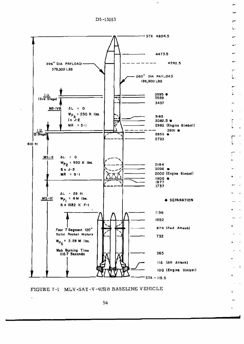
D5 -13183
3 9 6 " D1A PAYLOAD
379,300 LBS
STA 4 8 0 4 , 5
I.U. (3rd Stage]
MS-M flL = 0
Wp = 9 3 0 K lbs.
5 x J - 2
MR = 5 = 1
N
MS-IC
fiU = 28 ft.
Wp = SM lbs.
5 1 1522 K F-l
T Four 7 Segment (20 Sol id Rochet Motors
WD '- 2 .28 M lbs.
Web Burning Time 110.7 Seconds
i i i
4 4 7 3 . 5
4 2 8 2 . 5
2 6 0 DIA PAYLOAD
139,300 LBS
3595 3559
3437
3165 3082 .5 •
2982 (Engine Qimbal)
2891 • 2855 • 2 7 2 3
2184 2096 •
2000 (Engine Gitnba!)
1900 • 1877 1737
• SEPARATION
1196
1052
8 7 4 (Fwd At tach)
7 3 2
365
116 (Aft At tach)
100 (Engine Qimbsl]
STA - [15.5
FIGURE 7-1 MLV-SAT>V-4{S)B BASELINE V E H I C L E
54

D5-13183
7 . 0 M L V - S A T - V - 4 ( S ) B
The S A T - V - 4 ( S ) B (See F i g u r e 7-1) i s a S a t u r n V veh ic le with lengthened f i r s t s t a g e , adap ted to a c c e p t a t t a c h m e n t of four 120-inch d i a m e t e r sol id m o t o r s .
The veh ic l e as defined in the t r a d e s tudy ac t iv i t y and s tudied in de ta i l in the P h a s e II ac t iv i ty i s a f e a s i b l e and cos t effect ive conf igura t ion and i s , t h e r e f o r e , a logical cand ida te to p r o v i d e pay loads in e x c e s s of those c u r r e n t l y a v a i l a b l e with the Sa tu rn V veh ic le . Mo m a j o r p r o b l e m a r e a s w e r e ident i f ied for. e i the r d e v e l o p m e n t or p roduc t i on of th i s veh i c l e .
7. 1 CONFIGURATION S E L E C T I O N (PHASE I)
By va ry ing t he n u m b e r of so l id r o c k e t m o t o r s e g m e n t s (and thus sol id p r o p e l l a n t weight ) , and c o n s i d e r i n g both op t imized length and fixed length c o r e s t a g e s , a n u m b e r of r e l a t e d SAT-V-4(S)B v e h i c l e s w e r e evolved. P a y l o a d capab i l i t y and c o s t s w e r e e s t a b l i s h e d for t h e s e veh i c l e s in o r d e r to c h o o s e one a r r a n g e m e n t for m o r e de t a i l ed a n a l y s i s .
7. 1. 1 Cand ida te Conf igura t ions
F o r the t r a d e study both two and t h r e e s t a g e o p e r a t i o n was c o n s i d e r e d . The veh ic le he igh t was fixed a t 410 feet for both the two and t h r e e s t age con f igu ra t i ons . P r o p u l s i o n and engine type for a l l s t a g e s was fixed to c o r r e s p o n d to the b a s e l i n e AS-5l6 veh i c l e . Vary ing we igh t s of p rope l l an t and c o r r e s p o n d i n g s t a g e lengths w e r e s tud ied for al l s t a g e s . F o u r 120-inch so l id p r o p e l l a n t r o c k e t m o t o r s w e r e a t t ached to the veh i c l e for t h r u s t a u g m e n t a t i o n . The n u m b e r of s e g m e n t s in the so l id m o t o r s was v a r i e d be tween five and s e v e n . The c h a r a c t e r i s t i c s of each so l id m o t o r w e r e spec i f i ed by M S F C . Signif icant so l id m o t o r p a r a m e t e r s a r e shown in Tab le 7 -1 . The v e h ic le liftoff weight was v a r i e d to m a i n t a i n a liftoff t h r u s t - t o - w e i g h t of a p p r o x i m a t e l y 1.25.
IN
BO
14
7 .1 .2 T r a d e S tud ies
- 5 *
| ltd
F i g u r e 7-2 i s typ ica l of the p a r a m e t r i c p e r f o r m a n c e da t a p r e p a r e d for the t r a d e s tudy . F i g u r e 7-2 i l l u s t r a t e s the net payload v e r s u s the n u m b e r of s e g m e n t s in the 120-inch m o t o r s for the t h r e e - s t a g e veh i c l e . Th is c u r v e shows two cond i t i ons , o p t i m i z e d f i r s t - s t a g e p r o p e l l a n t weight wi th the upper s t a g e p r o p e l l a n t
SJWQ
HMD SOLID MOTORS
OPTIMIZED-
* - li ZERO MOTORS
SO 5 <
NO, OF SEGMWTS
F I G U R E 7-2 TRADE STUDY P E R F O R M A N C E DATA
55
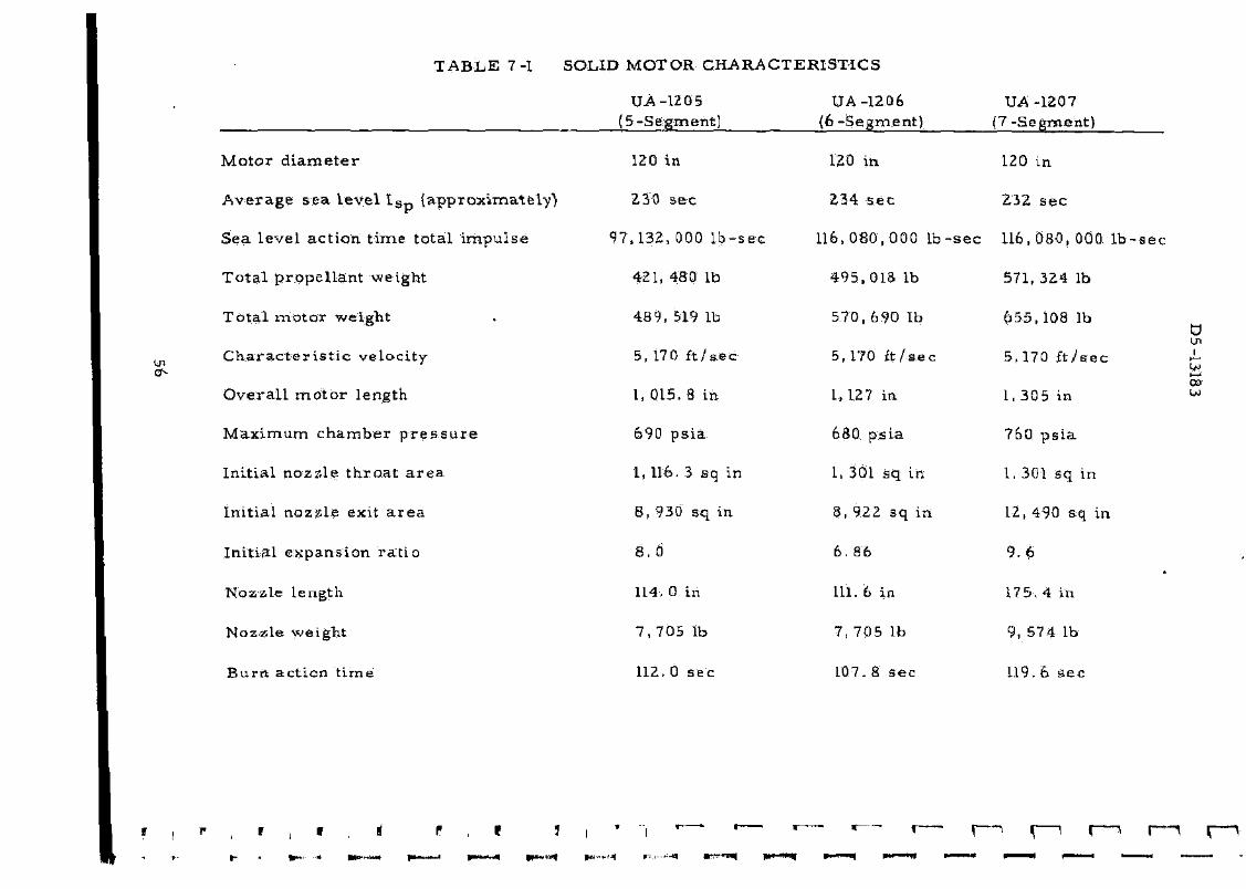
T A B L E 7-1 SOLID MOTOR C H A R A C T E R I S T I C S
UA -1205 UA -120 15-Segment) ( 6 - S e g m
M o t o r d i a m e t e r 120 in 120 in
A v e r a g e s e a l e v e l I S p ( a p p r o x i m a t e l y ) 230 s e c 234 s e c
Sea l eve l a c t i o n t i m e to t a l i m p u l s e 97, 132, 000 l b - s e c 116, 080,
T o t a l p r o p e l l e n t we igh t 421, 480 lb 4 9 5 . 0 1
T o t a l m o t o r we igh t . 489, 519 lb 570, 69
C h a r a c t e r i s t i c v e l o c i t y 5,170 f t / s e c 5,170 f
O v e r a l l m o t o r l eng th 1, 015. 8 in 1, 127 i
M a x i m u m c h a m b e r p r e s s u r e 690 p s i a 680 ps
In i t i a l n o z a l e t h r o a t a r e a 1, 116. 3 sq in 1, 301 s
In i t ia l n o z z l e exit a r e a 8, 930 sq in. 8, 922
In i t i a l e x p a n s i o n r a t i o 8. 0 6. 86
Nozz l e l eng th 114, 0 in 111. 6 i
N o z z l e we igh t 7 , 7 0 5 1b 7 , 7 0 5
B u r n ac t ion t i m e 112. 0 s e c 107. 8
•Mr-Ma p i • . I. I ,~ - - -9« p f w t |~"-(-H P~ i >*
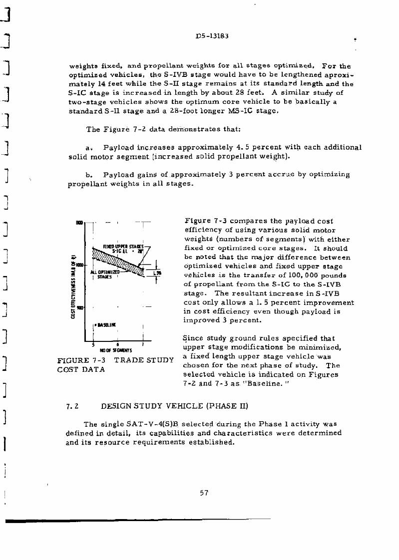
D5-13183
weights fixed, a n d p r o p e l l a n t weights for a l l s t a g e s o p t i m i z e d . F o r the o p t i m i z e d v e h i c l e s , the S-IYB s t a g e would have to be l eng thened a p r o x i -m a t e l y 14 fee t whi le t he S-II s t age r e m a i n s at i t s s t a n d a r d length and the S-IC s t a g e i s i n c r e a s e d in length by about 28 feet . A s i m i l a r study of t w o - s t a g e v e h i c l e s shows the o p t i m u m c o r e vehic le to b e b a s i c a l l y a s t a n d a r d S-II s t a g e and a 28- foo t l onge r MS-IC s t a g e .
The F i g u r e 7-2 da t a d e m o n s t r a t e s tha t :
a . P a y l o a d i n c r e a s e s a p p r o x i m a t e l y 4 . 5 p e r c e n t with each add i t iona l so l id m o t o r s e g m e n t ( i n c r e a s e d so l id p r o p e l l a n t we igh t ) .
b . P a y l o a d gains of a p p r o x i m a t e l y 3 p e r c e n t a c c r u e by op t imiz ing p r o p e l l a n t we igh t s in a l l s t a g e s .
HOD
&MD
I no
I'HSaiH
NO0F5FGMENTS
FIGURE 7-3 T R A D E STUDY COST DATA
F i g u r e 7-3 c o m p a r e s t he pay load cos t efficiency of us ing v a r i o u s so l id m o t o r weights ( n u m b e r s of s e g m e n t s ) with e i t h e r fixed or o p t i m i z e d c o r e s t a g e s . It should be noted tha t the ma jo r d i f fe rence be tween op t imized veh i c l e s and f ixed upper s t age veh ic les i s the t r a n s f e r of 100, 000 pounds of p r o p e l l a n t f r o m the S- IC t o t he S-IVB s t a g e . The r e s u l t a n t i n c r e a s e in S-IVB cos t only a l lows a 1. 5 p e r c e n t i m p r o v e m e n t in cos t efficiency even though payload i s i m p r o v e d 3 p e r c e n t .
Since study g round r u l e s spec i f i ed that upper s t age modi f i ca t ions be min imized , a fixed length upper s t age veh ic l e was chosen for the next phase of s tudy . The s e l e c t e d veh ic l e i s i nd i ca t ed on F i g u r e s 7-2 and 7-3 a s " B a s e l i n e . "
7.2 DESIGN STUDY VEHICLE (PHASE H)
The s ing le S A T - V - 4 ( S ) B s e l e c t e d dur ing the P h a s e I ac t iv i ty was defined in de ta i l , i t s c apab i l i t i e s and c h a r a c t e r i s t i c s w e r e d e t e r m i n e d and i t s r e s o u r c e r e q u i r e m e n t s e s t a b l i s h e d .
57

D5-13183
7 . 2 . 1 Vehic le D e s c r i p t i o n
The base l ine S A T - V - 4 ( S ) B vehic le i s shown in F i g u r e 7 -1 . It i n c o r p o r a t e s s t a n d a r d l eng th u p p e r s t a g e s and a 28-foot l onge r f i r s t - s t a g e a u g m e n t e d by four s e v e n - s e g m e n t 120-inch r o c k e t m o t o r s . The sol id m o t o r s , as d e s i g n a t e d by M S F C , c o n f o r m to p r e l i m i n a r y des igns deve loped by Uni ted Technology C e n t e r for T i t a n HI -C a p p l i c a t i o n s . E a c h moto r has an i n i t i a l sea l eve l t h r u s t of 1. 4 mi l l ion pounds and a p r o p e l l a n t weight of 579, 000 p o u n d s . E a c h m o t o r has a l iquid in jec t ion (NpO'j) t h r u s t vec to r c o n t r o l s y s t e m to augmen t the con t ro l c a p a b i l i t i e s of the g imba led F - i eng ines d u r i n g flight th rough the m a x q r e g i m e . The l iquid c o r e s t a g e s of S A T - V-4(S)B a r e equipped with s t a n d a r d F - 1 and J - 2 eng ines . The f i r s t s t a g e of the veh ic le i s r o t a t e d 45 d e g r e e s f r o m i ts pos i t ion in the s t a n d a r d S a t u r n V conf igura t ion to m i n i m i z e the i m p a c t on launch f ac i l i t i e s and o p e r a t i o n s . T h e second s tage is s t a n d a r d
S-II length with a p r o p e l l a n t capac i ty of 930, 000 p o u n d s . The th i rd s t age (for t h r e e - s t a g e app l i ca t i ons ) is s t a n d a r d S-IVB length with 230, 000 pounds p r o p e l l a n t c a p a c i t y . Since s tudy funds and t im ing w e r e l imi t ed , the d e s i r a b l e i n c r e a s e d l e n g t h S - I V B was not s tud ied and the S-II s t a g e for MLV-SAT-V-25 (S ) w a s u s e d d i r e c t l y on S A T - V - 4 ( S ) B .
7 . 2 . 2 D e s i g n Study R e s u l t s
The SAT-V-4{S)B t w o - s t a g e payload capabi l i ty to 100 n a u t i c a l m i l e s o r b i t i s 379 t h o u sand pounds and i t s 72 h o u r lunar in jec t ion t h r e e - s t a g e capabi l i ty is 139 t h o u s a n d pounds .
Use of th i s v e h i c l e w a s a l s o c o n s i d e r e d for a p p l i c a t i o n w h e r e the c o r e veh ic le {liquid s t a g e s without so l id s ) cou ld be flown by i t se l f or with only two s t r a p - o n so l id m o t o r s . The pay loads ident i f ied for t h e s e a l t e r n a t e s a r e as shown in Table 7-H.
m LAWH AirMiJ™ 1 1 i S - '
*v -? ̂ . BIHtCTASCENT
"̂ i% ?*: 180°
5 300 ^ S fs
"fa * ̂ ^ a 1 v N V _
**3 $ V - s ,
4 m 4 m CUU
1 V
100 so ORBIT. ALTITUDf-NM
300
F I G U R E 7 -4 ORBIT A L T I T U D E -AZIMUTH PAYLOAD CAPABILITY
Addi t iona l s t u d i e s iden t i f ied i n f o r m a t i o n useful for m i s s i o n planning. P a y l o a d s a v a i l a b l e for v a r i o u s o rb i t a l a l t i t udes be tween 30 and 300 nau t i ca l m i l e s and l aunch a z i m u t h s be tween 45 d e g r e e s and 180 d e g r e e s a r e shown in F i g u r e 7 - 4 . P o l a r and n e a r p o l a r qrb.it p ay loads a r e shown
53
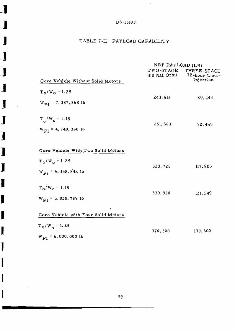
D5-13183
TABLE 7-II PAYLOAD CAPABILITY
NET PAYLOAD (LB) TWO-STAGE THREE-STAGE 100 NM Orbit 72-hour Lunar
Core Vehicle Without Solid Motors Injection
T 0 / W 0 =1 .25 243,512 89,444
W„, = 7,387,368 lb
T /WQ = 1.18 ° 251,683 92,445
WD1 = 4,740,350 lb
Core Vehicle With Two Solid Motors
T 0 / W 0 = 1.25 320,725 117,805
Wts, - 5,358,842 lb
T o / W 0 = 1.18 330,920 121,549
WD1 = 5,855,789 lb
Core Vehicle with Four Solid Motors
T 0 / W 0 = 1.25 379,300 139,300
W™ * 6,000,000 lb
59
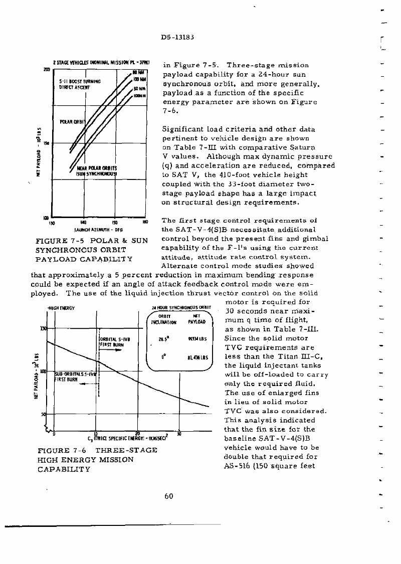
D5-13183
?STAavrHICLES I N™ lHAl«.S5IONPL-3mi i n F i g u r e 7 _ 5 _ T h r e e . s t a g e mission
payload capab i l i ty f a r a 2 4 - h o u r sun s y n c h r o n o u s o r b i t , and m o r e g e n e r a l l y , payload a s a function of the spec i f ic e n e r g y p a r a m e t e r a r e shown on F i g u r e 7 -6 .
Signif icant load c r i t e r i a and o t h e r data p e r t i n e n t to veh ic le des ign a r e shown on Tab l e 7-III with c o m p a r a t i v e S a t u r n V v a l u e s . Al though m a x d y n a m i c p r e s s u r e (q) and a c c e l e r a t i o n a r e r e d u c e d , c o m p a r e d to SAT V, the 410-foot veh i c l e he ight coupled with the 33-foot d i a m e t e r t w o -s t age payload shape has a l a r g e i m p a c t on s t r u c t u r a l de s ign r e q u i r e m e n t s .
The f i r s t s t a g e con t ro l r e q u i r e m e n t s of the SAT-V-4{S)B n e c e s s i t a t e add i t iona l con t ro l beyond the p r e s e n t f ins and g imba l capab i l i ty of the F - l ' s u s ing the c u r r e n t a t t i t u d e , a t t i t ude r a t e c o n t r o l s y s t e m . A l t e r n a t e c o n t r o l mode s t u d i e s showed
tha t a p p r o x i m a t e l y a 5 p e r c e n t r educ t ion in m a x i m u m bending r e s p o n s e could be e x p e c t e d if an ang le of a t t ack feedback con t ro l m o d e w e r e e m ployed . T h e u s e of t he l iqu id in jec t ion t h r u s t vec to r con t ro l on the so l id
m o t o r is r e q u i r e d for
iw l « 150
UUNCHAZIMfTH- DFG
FIGURE 7-5 POLAR & SUN SYNCHRONOUS ORBIT PAYLOAD CAPABILITY
-HIGHFMESGV 21 HOUR SYNCHRONOUS ORBIT
C, (TWICE SPECIFIC ENERGY) MKMJ5K)2
FIGURE 7-6 T H R E E - S T A G E HIGH ENERGY MISSION CAPABILITY
30
30 s e c o n d s n e a r m a x i m u m q t i m e of flight, a s shown in T a b l e 7-111. S ince the so l id moto r TVC r e q u i r e m e n t s a r e l e s s than the T i t an I I I -C , the l iquid in jec tan t t anks wil l be of f - loaded to c a r r y only the r e q u i r e d fluid. The u s e of e n l a r g e d fins in l ieu of so l id m o t o r TVC was a l s o c o n s i d e r e d . Th i s a n a l y s i s ind ica ted tha t the fin s i z e for the b a s e l i n e SAT-V-4(S)B veh ic le would have to be double tha t r e q u i r e d for AS-5L6 {150 s q u a r e fee t
60
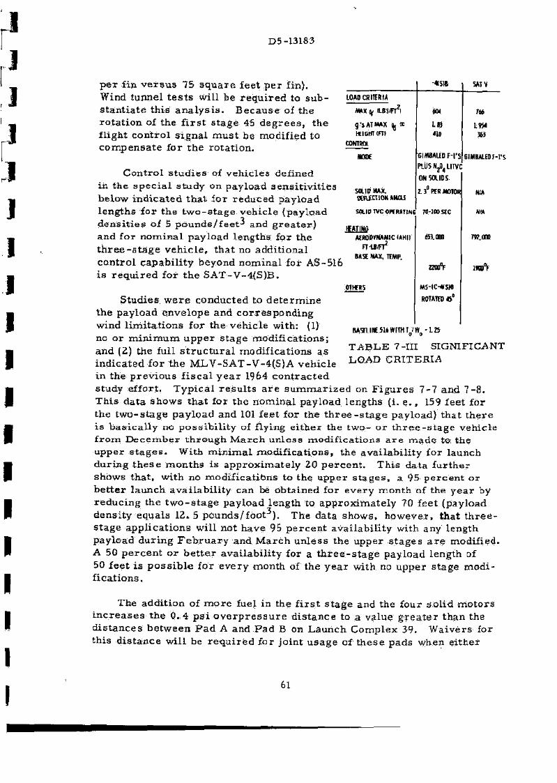
D5-13183
-*S)B MTV p e r fin v e r s u s 75 s q u a r e fee t p e r f in) . Wind tunne l t e s t s will be r e q u i r e d to s u b s t a n t i a t e this a n a l y s i s . B e c a u s e of the r o t a t i o n of the f i r s t s t a g e 45 d e g r e e s , the fl ight c o n t r o l s i g n a l m u s t be modif ied to c o m p e n s a t e for t he ro t a t i on .
C o n t r o l s t u d i e s of veh i c l e s defined in the s p e c i a l s tudy on payload s e n s i t i v i t i e s be low i n d i c a t e d t h a t fo r r e d u c e d pay load l eng ths for t he t w o - s t a g e veh ic l e {payload d e n s i t i e s of 5 pounds/feet-* and g r e a t e r ) and for n o m i n a l payload l eng ths for the t h r e e - s t a g e v e h i c l e , t h a t no add i t iona l c o n t r o l c a p a b i l i t y beyond n o m i n a l for AS-516 is r e q u i r e d for t he S A T - V - 4 ( S ) B .
S tud ies w e r e conduc ted to d e t e r m i n e t he pay load e n v e l o p e and c o r r e s p o n d i n g wind l i m i t a t i o n s for the veh i c l e with: (1) no or m i n i m u m u p p e r s t a g e modi f i ca t ions ; and (2) the full s t r u c t u r a l modi f i ca t ions a s ind ica ted for the M L V - S A T - V - 4 ( S ) A veh ic l e in the p r e v i o u s f i s c a l y e a r 1964 c o n t r a c t e d s tudy effort . T y p i c a l r e s u l t s a r e s u m m a r i z e d on F i g u r e s 7-7 and 7 - 8 . This da ta shows tha t for the n o m i n a l payload lengths (i . e . , 159 feet for the t w o - s t a g e p a y l o a d and 101 feet for the t h r e e - s t a g e payload) t ha t t h e r e i s b a s i c a l l y no p o s s i b i l i t y of flying e i t h e r the t w o - or t h r e e - s t a g e vehic le f r o m D e c e m b e r t h r o u g h M a r c h un l e s s modi f ica t ions a r e m a d e to the upper s t a g e s . With m i n i m a l mod i f i ca t i ons , the ava i l ab i l i ty for launch dur ing t h e s e m o n t h s i s a p p r o x i m a t e l y 20 p e r c e n t . This da ta f u r t h e r shows t ha t , with no modi f i ca t ibns to t he u p p e r s t a g e s , a 95 p e r c e n t o r b e t t e r l aunch a v a i l a b i l i t y can be ob ta ined for e v e r y mon th of the y e a r by r e d u c i n g the t w o - s t a g e pay load length to a p p r o x i m a t e l y 70 feet (payload dens i ty equals 12 .5 p o u n d s / f o o t 3 ) . The da ta s h o w s , h o w e v e r , t ha t t h r e e -s t a g e a p p l i c a t i o n s wi l l not have 95 p e r c e n t ava i l ab i l i ty with any length pay load d u r i n g F e b r u a r y and M a r c h u n l e s s the upper s t a g e s a r e modified-A 50 p e r c e n t o r b e t t e r ava i l ab i l i t y for a t h r e e - s t a g e pay load length of 50 fee t i s p o s s i b l e for e v e r y month of the y e a r with no u p p e r s t a g e m o d i f i ca t ions .
LOAD CHITfHIA
M A X ^ tLBSTT2! t£H m g ' lATMAX ^ tc WIGHT (FTI
L13
' ID L«* »3
CONTROL
MODE GIMBALEDF-rs
PlUSN^LITVC
ON SOLIDS
GIMBALEDF-1'S
SOLID MAX. DEFLECTION ANGLE
Z. 3° PER MOTOR NU
SOLID TVCOFf RATINC 70-100 SEC NU
HFATINO AERODYNAMIC MHI I
FT-UffT
653,000 Won
BASE MAX, TEMP.
coA waft
OTHERS MS-|C-*S»
ROTATED « "
BA5ELINE516WITHTIW - L S 0 0
T A B L E 7-III SIGNIFICANT LOAD CRITERIA
The add i t ion of m o r e fuel in the f i r s t s t a g e and the four s.olid m o t o r s i n c r e a s e s the 0..4 p s i o v e r p r e s s u r e d i s t a n c e to a value g r e a t e r than the d i s t a n c e s be twe en P a d A and P a d B on Launch Complex 39. W a i v e r s for th i s d i s t a n c e wil l be r e q u i r e d for jo in t u s a g e of t h e s e pads when e i ther
61
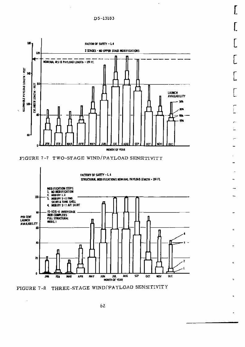
D5-13183
l»
120
FACTOR OF SAFETY • U
! STAGES - NO UPPER STAGE MODIFICATIONS
MONTH OF YEAR
FIGURE 7-7 T W O - S T A G E WIND/PAYLOAD SENSITIVITY
FACTORV0F SAFETY-L* STRUCTURAL MODIFICATIONS NOMINA! PAYLQAD LENGTH - W FT.
MODIFICATION STEPS L NO MODIFICATION t MODIFY I.U \ MODIFY S-l I FWO.
SKIRT I TANK SHELL 100
n PER COT LAUNCH AVAILABILITY
»
* N D O i r r S - l l AFT SKIRT
. IS- IWS- l l IKIERSTACE M M COMPLETES FULL STRUCTURAL MODS.)
JAN FEB MAR APR MAY JUN JUL AUG MONTH OF YEAR
OCT NOV DtC
FIGURE 7-8 T H R E E - S T A G E WIND/FA YLOAD SENSITIVITY
62

D5-13183
pad con ta ins a fueled c o r e veh i c l e with the so l id m o t o r s a t t ached . The acous t i c l eve l wi l l r e q u i r e p r o t e c t i o n of p e r s o n n e l d u r i n g launch.
F l i g h t and c r e w safe ty a r e s a t i s f a c t o r y for th is veh i c l e . C o m m u n i ca t ions for s o m e s t a t ions m a y p o s s i b l y be " b l a c k e d out" due to the exhaus t p lume i n t e r f e r e n c e . O t h e r s t a t i o n s , h o w e v e r , wi l l h a v e c l e a r c o m m u n i ca t ions du r ing t h e s e p e r i o d s a n d c a n p r o v i d e cont inuous c o m m u n i c a t i o n s .
A s s u m i n g an Apollo pay load and l aunch e s c a p e s y s t e m , t he a b o r t l ead t i m e fo r t h i s veh ic le Was deve loped for c o m p a r i s o n with that of the S a t u r n V. Us ing a so l id m o t o r T N T equ iva lency of 100 p e r c e n t , an a b o r t l ead t i m e of 2 . 76 s e c o n d s is r e q u i r e d for th i s veh ic le v e r s u s 2. 19 s e c o n d s for the S a t u r n V. A b o r t l ead t i m e i s t ha t t i m e p r i o r to explos ion of t he veh i c l e t h a t t h e l aunch e s c a p e s y s t e m f i r ing p u l s e m u s t be in i t i a ted . O t h e r s t u d i e s showed tha t no p r o b l e m s for a b o r t a r e an t i c ipa ted b e c a u s e of s e p a r a t i o n d y n a m i c s .
A e r o d y n a m i c hea t ing for the M X J V - S A T - V - 4 ( S ) E i s s igni f icant ly l o w e r than the S a t u r n V. The a e r o d y n a m i c heat ing i n d i c a t o r (AHI) at 653 , 000 foo t -pounds p e r s q u a r e foot fo r the S A T - V - 4 ( 5 ) B i s 18 p e r c e n t l o w e r than the n o m i n a l SAT V AHI va lue of 792, 000 foot -pounds p e r s q u a r e foot and 30 p e r c e n t be low the m a x i m u m AHI value for the Sa tu rn V of 924, 000 foot -pounds p e r s q u a r e foot. The shock wave f r o m the so l id m o t o r n o s e c a p m a y i m p i n g e on the f i r s t s t a g e n e a r the i n t e r t a n k a n d l o c a l i n s u l a t i o n m a y be r e q u i r e d .
The base hea t ing e n v i r o n m e n t is m o r e s e v e r e for the ML.V-SAT-V-4{S)B than for t he S a t u r n V due to the so l id m o t o r exhaus t p l u m e s . Howe v e r , hea t s h i e l d m a t e r i a l s can wi ths tand t he 2200 d e g r e e F t e m p e r a t u r e s an t i c ipa t ed s u c c e s s f u l l y . T h e aft so l id m o t o r a t t a c h m e n t s k i r t wi l l r e a c h 2480 d e g r e e s F . Insu la t ion p r o t e c t i o n on the aft s k i r t wi l l be r e q u i r e d . A b a s e hea t sh i e ld will a l s o be r e q u i r e d for e ach of the so l id m o t o r s .
The r e l i a b i l i t y of t he t w o - and t h r e e - s t a g e MLV-SAT~V-4(S)B veh ic le i s 0. 984 and 0 . 9 6 7 , r e s p e c t i v e l y , a s c o m p a r e d to . 990 and . 980 for the base l ine AS-516. The lower r e l i a b i l i t y c a n be a t t r i b u t e d to the m o d i f ica t ions to the s t a g e s and the add i t ion of the s t r a p - o n s o l i d m o t o r s .
S e p a r a t i o n of t he so l id m o t o r s f r o m the c o r e veh ic le can be a c c o m p l i shed s a t i s f a c t o r i l y u s i n g e x p l o s i v e s e p a r a t i o n d e v i c e s and the p r e s e n t Ti tan HIC s e p a r a t i o n r o c k e t m o t o r s .
63

D5-13183
Vehicle combined loads and acoustics a r e i l lustrated in F igure 7-9-The design loads a re approximately 60 percent higher than those for the standard Saturn V. The acoustic specification limits are exceeded at severa l locations on the f i r s t s tage. Acoustic requalification of approximately. 70 percent of the acoustically sensitive components on this stage will be required.
175
US
. 1»
« US
IN RIGHT LAUNCH INaiCHT
rLAUNCH 1 STATIC
\ \ | HHIHC| LAUNCH
. MI v ueumi if ( t u n
l*V-SAT-B-«SIB
MWXi^ff
. M A X * * r- M A X * * DJ|f-REBOUH0
FIGURE 7-9 ACOUSTIC ENVIRONMENT AND STRUCTURAL LOADS
Major vehicle changes including the impact of s t ruc tura l load increases a re summar ized on F igure 7-10. Dry weight increases a re also tabulated.
4.3 RESOURCES
The present stage and I. U. vendors were assumed to be contractors for the modified vehicle components. A dynamic test vehicle, s t ructura l test components and two R&D man-rat ing flight vehicles a re required.
The existing Dynamic Test facility will be employed to test the MLV-SAT-V-4(S)B-D. Necessary modifications include relocation of platforms for increased vehicle length and an additional hydrbdynarnic support.
64
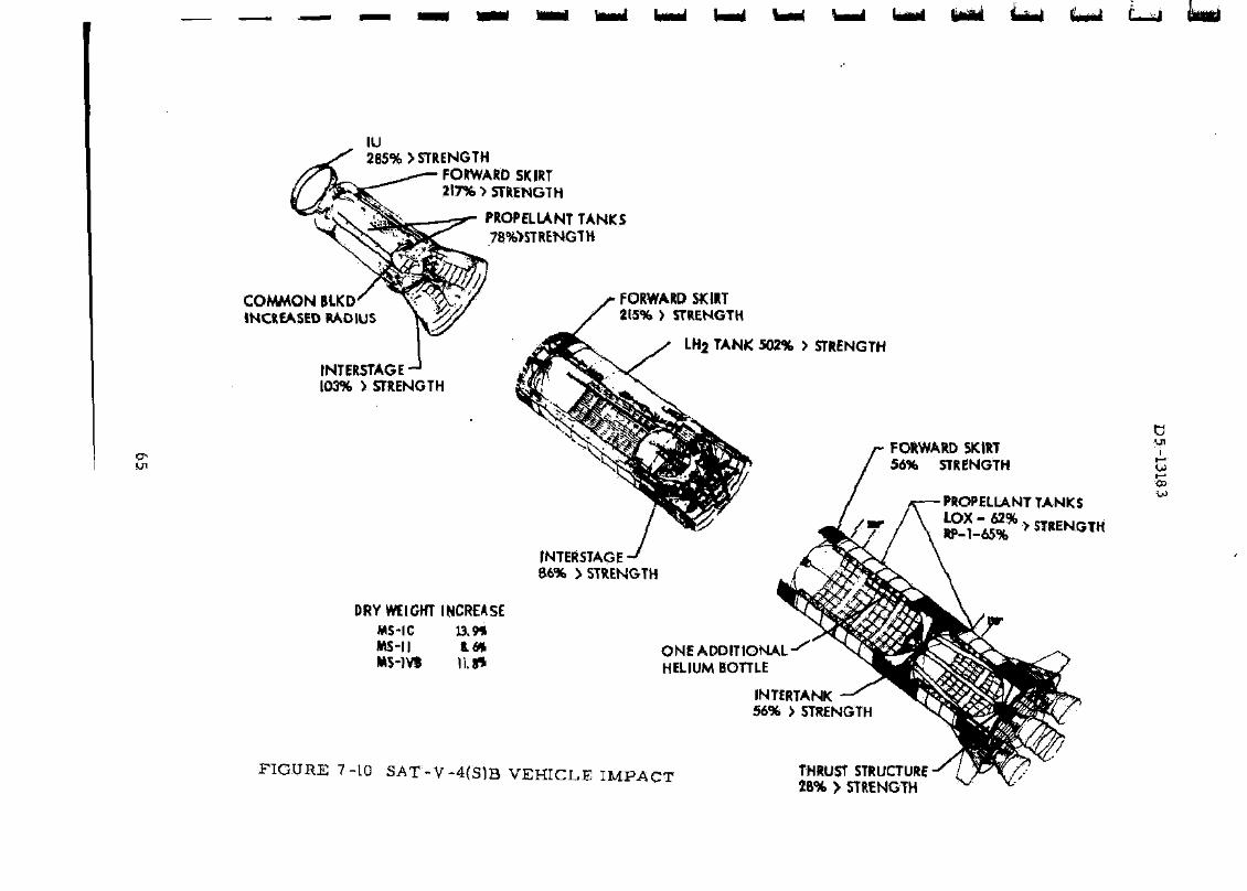
IU 2B5% > STRENGTH
FORWARD SKIRT 217% > STRENGTH
PROPELLANT TANKS 78%>STRENGTH
COMMON BLKD INCREASED RADIUS
INTERSTAGE 103% > STRENGTH
DRY WEIGHT INCREASE WS-IC 13.9% MS-II K.M. MS-1VS ||.f»
FORWARD SKIRT 215% > STRENGTH
LH2 TANK 502% > STRENGTH
INTERSTAGE' 66% > STRENGTH
ONE ADDITIONAL HELIUM BOTTLE
FIGURE 7-10 SAT-V-4{S)B VEHICLE IMPACT
INTERTANK 56% > STRENGTH
THRUST STRUC 28% > 5TREN

D5 -13183
The S- IC s t a g e of t h e d y n a m i c t e s t veh i c l e wi l l b e r e f u r b i s h e d a f te r t e s t and u s e d a s a flight a r t i c l e .
The 120-inch sol id r o c k e t m o t o r s wi th t h e i r t h r u s t vec to r c o n t r o l s y s t e m a r e a s s u m e d to be f l ight qual i f ied in the T i t an III-C veh ic le s y s t e m s .
A p roduc t i on r a t e of s i x v e h i c l e s p e r y e a r for a pe r iod of five y e a r s w a s u t i l i zed to a s s e s s p r o d u c t i o n i m p a c t .
MS- IC-4 (5 )B
The m a j o r i m p a c t of t h e f i r s t s t age changes on Michoud fac i l i t i e s w i l l be due to the added S R M functions and m a n u f a c t u r e of the SRM aft Ski r t s t r u c t u r e . Addi t iona l a s s e m b l y equ ipment , checkou t and handl ing , and t r a n s p o r t a t i o n e q u i p m e n t wil l be r e q u i r e d . The aft a t t a c h m e n t s t r u c t u r e i s a m a r a g i n g s t e e l s t r u c t u r e r e q u i r i n g bo r ing m a c h i n e s , welding f i x t u r e s , and add i t iona l weld ing faci l i ty a r e a . The h e a v i e r and longe r f i r s t s t a g e wil l r e q u i r e r e w o r k of much of the ex i s t ing equ ipmen t .
Major tool ing and a s s e m b l y r e q u i r e m e n t s a t Michoud inc lude an add i t iona l tank a s s e m b l y s t a t i o n , an add i t iona l t ank c lean ing pos i t ion , and s o m e a d d i t i o n a l and m o d i f i e d too l ing . Add i t iona l w a r e h o u s i n g , qua l i ty a s s u r a n c e , and r e c e i v i n g i n s p e c t i o n a r e a s wil l be r e q u i r e d . T h e s e addi t ions p r o v i d e t h e capab i l i ty of i n t r o d u c i n g t he new conf igur a t i o n wi th m i n i m u m d o w n t i m e .
Modif icat ion of the S- IC t e s t f i r ing s t a n d s a t M T F and MSFC a r e r e q u i r e d only due to i n c r e a s e d s t age leng th and p r o p e l l a n t c a p a c i t y . Solid m o t o r s wi l l not be f i r e d in conjunct ion wi th the s t a g e s t a t i c t e s t .
The s t age t r a n s p o r t e r and the b a r g e s m u s t be modi f ied to a c c o m m o d a t e t he i n c r e a s e d s t age l eng th . Addi t iona l so l id m o t o r handl ing and t r a n s p o r t a t i o n equ ipment wi l l b e r e q u i r e d .
MS-II -4(S)B
Manufac tu r ing r e q u i r e m e n t s for the MS-II-4{S)B s t age a r e defined by the s c h e d u l e d e l i v e r y d a t e s and the s t a g e S t r u c t u r a l m o d i f i c a t i o n s . A s e p a r a t e s t age wil l be m a n u f a c t u r e d to be u t i l i zed for both s t a t i c s t r u c t u r e s t e s t and for s t a g e dynamic t e s t . D e l i v e r y of th i s s t a t i c / dynamic (S/D) s t a g e r e q u i r e s tha t t he s t a n d a r d S - n p roduc t i on be a c c e l e r a t e d to a c c u m u l a t e suff icient s t a g e s to m a i n t a i n a c o n s t a n t d e l i v e r y r a t e at one Stage e v e r y two m o n t h s .
The r e v i s e d s t r u c t u r a l d e s i g n wil l r e q u i r e modi f ica t ion of the f ab r i c a t i o n and a s s e m b l y t o o l s for the f o r w a r d and aft s k i r t s , LH? t ank
66
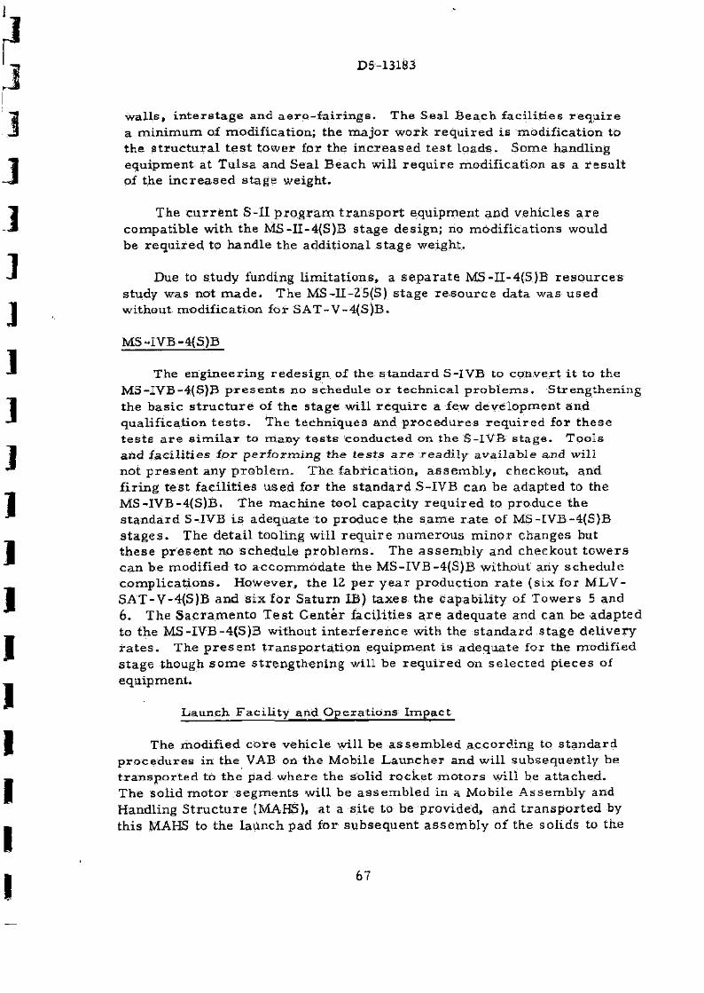
D5-13183
w a l l s , i n t e r s t a g e and a e r o - f a i r i n g s . The Sea l B e a c h f a c i l i t i e s r e q u i r e a m i n i m u m of modi f ica t ion ; the m a j o r work r e q u i r e d i s m o d i f i c a t i o n to the s t r u c t u r a l t e s t t o w e r for the i n c r e a s e d t e s t l o a d s . Some handl ing equ ipment a t T u l s a and Sea l B e a c h wil l r e q u i r e modi f i ca t ion as a r e s u l t of the i n c r e a s e d s t age weight .
The c u r r e n t S-II p r o g r a m t r a n s p o r t equ ipmen t and v e h i c l e s a r e compa t ib l e with the MS-II-4{S)B s t age des ign; no mod i f i ca t ions would be r e q u i r e d to hand le the add i t iona l s t a g e weight .
Due to s tudy funding l i m i t a t i o n s , a s e p a r a t e MS-I I -4(S)B r e s o u r c e s s tudy was not m a d e . The MS-II -25(S) s t age r e s o u r c e da ta was u s e d without modi f ica t ion for S A T - V - 4 ( S ) B .
MS-IVB-4{S)B
The e n g i n e e r i n g r e d e s i g n of the s t a n d a r d S-IVB to c o n v e r t i t to the MS-IVB-4(S)B p r e s e n t s no schedu le o r t e c h n i c a l p r o b l e m s . S t r eng then ing the b a s i c s t r u c t u r e of the s t a g e wil l r e q u i r e a few d e v e l o p m e n t and qua l i f i ca t ion t e s t s . The t e chn iques and p r o c e d u r e s r e q u i r e d for t h e s e t e s t s a r e s i m i l a r to many t e s t s conduc ted on the S- lVB s t a g e . T o o l s and f a c i l i t i e s fo r p e r f o r m i n g the t e s t s a r e r e a d i l y a v a i l a b l e a n d wi l l not p r e s e n t any p r o b l e m . The f ab r i ca t ion , a s s e m b l y , checkout , and f i r i ng t e s t f ac i l i t i e s u sed for the s t a n d a r d S-IVB can be adap ted to the MS- IVB-4(S)B . The m a c h i n e too l capac i ty r e q u i r e d to p r o d u c e the s t a n d a r d S-IVB i s adequa te to p r o d u c e the s a m e r a t e of MS-IVB-4(S)B s t a g e s . The d e t a i l tool ing wil l r e q u i r e n u m e r o u s m i n o r changes but t h e s e p r e s e n t no s c h e d u l e p r o b l e m s . The a s s e m b l y and checkout t o w e r s can b e modif ied to a c c o m m o d a t e the MS-IVB-4(S)B wi thout any s c h e d u l e c o m p l i c a t i o n s . Howeve r , the 12 p e r y e a r p roduc t i on r a t e ( s ix for M L V -SAT-V-4(S)B and s i x for Sa tu rn IB) t a x e s the capab i l i t y of T o w e r s 5 and 6. The S a c r a m e n t o T e s t C e n t e r f ac i l i t i e s a r e adequa t e and c a n be adap ted to the MS-IVB-4(S)B without i n t e r f e r e n c e with the s t a n d a r d s t a g e d e l i v e r y r a t e s . The p r e s e n t t r a n s p o r t a t i o n equ ipment i s a d e q u a t e for the modif ied s t a g e though s o m e s t r e n g t h e n i n g wil l be r e q u i r e d on s e l e c t e d p i ece s of equipment*
L a u n c h F a c i l i t y and O p e r a t i o n s I m p a c t
The modi f ied c o r e veh i c l e wil l be a s s e m b l e d a c c o r d i n g to s t a n d a r d p r o c e d u r e s in the VAB on the Mobi le L a u n c h e r and wil l subsequen t l y be t r a n s p o r t e d to t he pad w h e r e the sol id r o c k e t m o t o r s will be a t t a c h e d . The Solid m o t o r s e g m e n t s wi l l be a s s e m b l e d in a Mobi le A s s e m b l y and Handling S t r u c t u r e (MAHS), at a s i t e to be p rov ided , and t r a n s p o r t e d by th i s MAHS to the l a u n c h pad fo r s u b s e q u e n t a s s e m b l y of the so l ids to the
67

D5-13183
ELEVATION
FIGURE 7-11 M O B I L E ASSEMBLY AND HANDLING STRUCTURE
c o r e v e h i c l e . The MAHS wi l l m a t e with the m o b i l e l a u n c h e r for th i s a s s e m b l y o p e r a t i o n and handl ing equ ipment within the MAHS will be u t i l i zed for p l a c e m e n t of t he s o l i d m o t o r s a g a i n s t the c o r e veh ic le {s«e F i g u r e 7-11). After a s s e m b l y of the so l id m o t o r s , the MAHS will be r e m o v e d and r e p l a c e d by the s e r v i c e t o w e r . N o r m a l o p e r a t i o n s for the c o r e veh ic le will be r e s u m e d and add i t i ona l o p e r a t i o n s a s r e q u i r e d for sol id m o t o r final checkou t and a r m i n g will be a c c o m p l i s h e d .
The ex i s t ing VAB with w o r k p l a t f o r m loca t i ons a l t e r e d and the ex i s t ing l aunch p a d and i t s exis t ing, f lame t r a n c h can be u t i l i zed . The c r a w l e r t r a n s p o r t e r r o a d w a y s a r e sufficient for th i s veh ic le with the except ion of the r e q u i r e m e n t for s o m e add i t iona l c r a w l e r t r a n s p o r t e r r o a d w a y s a s r e q u i r e d for a c c e s s to the so l id m o t o r a s s e m b l y s i t e . Ma jo r i m p a c t a r e a s inc lude the deve lopmen t and c o n s t r u c t i o n of the MAHS and modi f ica t ions to the m o b i l e l a u n c h e r (ML) to i n c r e a s e i t s deck load capac i ty , to r e l o c a t e the swing a r m s , to r e l o c a t e the t a i l s e r v i c e m a s t s and hblddown s t r u c t u r e , and to e n l a r g e the a s p i r a t o r hole to a l low add i t i ona l
68
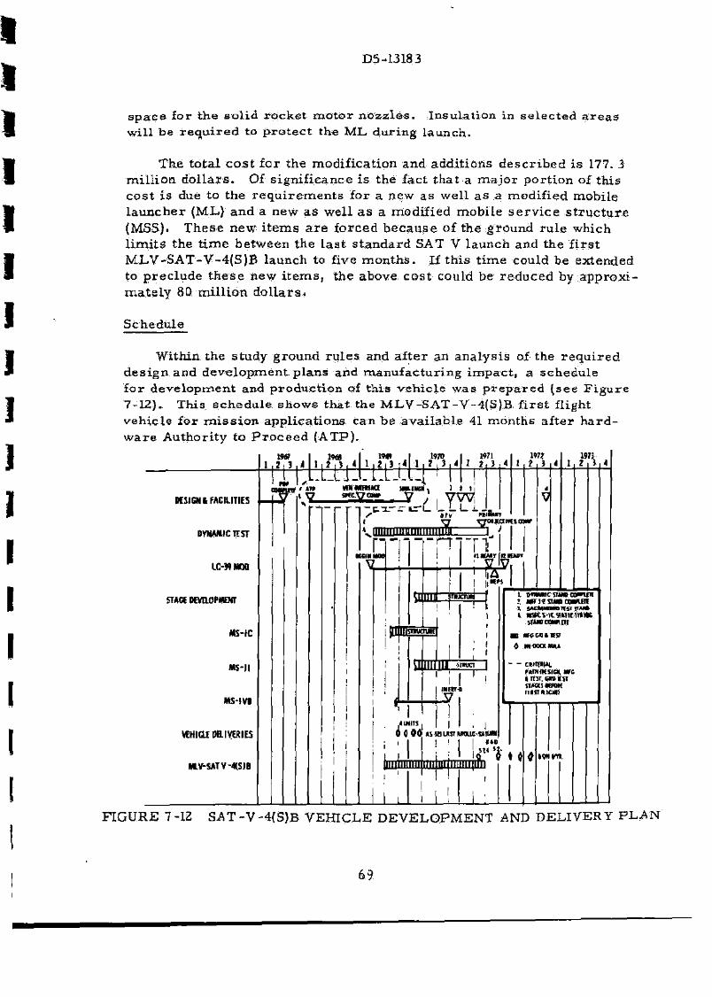
D5-13183
s p a c e for t he s o l i d r o c k e t m o t o r n o z z l e s . In su la t ion in s e l e c t e d a r e a s wi l l he r e q u i r e d tQ p r o t e c t the M L du r ing launch .
The to t a l c o s t fo r the modi f ica t ion and addi t ions d e s c r i b e d i s 177. 3 m i l l i o n d o l l a r s . Of s ign i f i cance i s the fac t t h a t a m a j o r po r t i on of th is c o s t i s due to the r e q u i r e m e n t s for a new as wel l a s a modi f ied mobi le l a u n c h e r (ML) and a new a s wel l a s a modif ied mobi l e s e r v i c e s t r u c t u r e (MSS). T h e s e n e w i t e m s a r e fo rced b e c a u s e of the g round r u l e which l i m i t s the t i m e be tween the l a s t s t a n d a r d SAT V l aunch and the f i r s t M L V - S A T - V - 4 ( S ) B launch to f i r e m o n t h s . If t h i s t i m e could be ex tended to p r e c l u d e t h e s e new i t e m s , the above c o s t could be r e d u c e d by a p p r o x i m a t e l y 80 m i l l i o n d o l l a r s .
Schedu le
Within the s tudy g round r u l e s and a f t e r an a n a l y s i s of the r e q u i r e d d e s i g n and d e v e l o p m e n t p l a n s and m a n u f a c t u r i n g i m p a c t , a s chedu le for d e v e l o p m e n t and p roduc t i on of t h i s v e h i c l e was p r e p a r e d ( s e e F i g u r e 7-12). This s c h e d u l e shows tha t the MLV-SAT-V-4(S)B . f i r s t flight veh ic le for m i s s i o n app l i ca t ions can b e a v a i l a b l e 41 mon ths af ter h a r d w a r e Author i ty to P r o c e e d ( A T P ) .
DESIGN t FACILITIES
DYNAMIC TEST
LC-39MOD
STAGE DEVELOPMENT
MS-IC
MS-JI
JWS-IV1
VEHICLE DELIVERIES
KV-SATV- *SJB
1 , i t 3 , l t tHI IW I mt i two l , i t4 1 . 1 , 1 , 4 I
W71 2j_J * I
\ ~^
MNMHHKi sKtt7cmf 3~; ' *_Li
n - t x - r t r L L L L i „
1*7? 1 3 «
KCMMOt
£ IICTWCTJK
S rTOMllMinr
n •1KMT
A mil f -H
am nx unr-n
imik
< Wilis | I , I 0 00 urauKTuaia-ttiuM
HO I *
B A
I DAMNC true covin
j. s«MmniHijr<u*
SfUOCWIEIt
•1 HCCOIIP
4 wooamM
- - cuqtM MIHMtSIGX MZ
«ifST.cn it n
FiifinicM)
mini milium v" * « IWW*.
FIGURE 7-12 SAT-V-4 (S )B V E H I C L E D E V E L O P M E N T AND DELIVERY P L A N
69
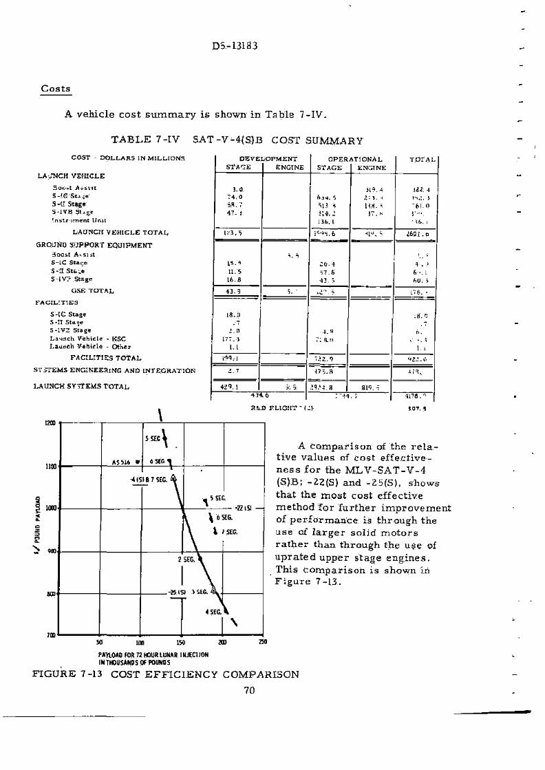
DS-13183
Costs
A vehicle cost summary is shown in Table 7-IV.
TABLE 7-IV SAT-V-4(S)B COST SUMMARY
COST - D O L L A R S IN M I L L I O N S
L A J N C H VEHICLE
5ot-*t A s s i s t S-iC S t j 4 e S-t l S tage 5- iVB S U g e ' . na t r ' imea t Unit
LAUNCH V E H I C L E T O T A L
GHOUND S U P P O R T E Q U I P M E N T 3 o o s t A151 st S-IC S t a e e S-H S t » ; e 5 - i V ? Stage
GSE T O T A L
F A C I L I T I E S
S-IC Slage S - n 5 ta»e S-1V2 Stage L a u n c h Vehic le - KSC L a u n c h V e h i c l e - O t h e r
F A C I L I T I E S T O T A L
SYSTEMS ENGINEERING AND I N T E G R A T I O N
l ^ U N C H SYTTEMS T O T A L
R I D F L I G H T n II)
D E V E L O P M E N T S T A ^ E ENGINE
O P E R A T I O N A L STAGE ENGINE
T O T A L
1.0 7 4 . 0 =S.7 47- i
B l 4 . T
iW. 2 136,1
319.4 2T3. -1 H * . i
17. i*
III. 4 H,!. i "*.t.O ! ' " • .
• i & . i
1 ^ , 1
2 6 - 4 =.7.6 4 3 . i
-q". - i 6QI . l i
LS.5 II. 5
Ifc.8
•*. i
2 6 - 4 =.7.6 4 3 . i
4 . i 6 - . 1 hi), i
4 3 . 3 j . W. 5 r . 6 . •
18.1)
2-0 177.3
l . l
4 . " 7; 3.!i
.S.n
[•?<*.! 7.J2.9 ••ii.o
2-7 475.R *:"..
429 .1 3' . T» i i .M-B 81'J. = 4 3 u : '44 1178.Ti
507, S
A comparison of the r e l a tive values of cost effectiveness for the MLV-SAT-V-4 (S)B; -22(S) and -25(S), shows that the most cost effective method for further improvement of performance is through the use of l a rger solid motors ra ther than through the use of uprated upper stage engines. This comparison is shown in Figure 7-13.
FAYIOAD FOR 72 HOUR LUNAR INJECT JON
IN THOUSANDS OF POUNDS
FIGURE 7-13 COST EFFICIENCY COMPARISON
70
D5-L3183
71

2 6 0 " DIA PAYLGAD 220,200 lbs.
3697 3661 3539
STA 4 804.5
4 4 3 9 5
4248.5
3002.5 2986; 5 • 2893 (Engine Gimbol)
2795 • £759 •
2627
2088 2 0 0 0 • 1904 {Engine Gimbol) 1804 • 1781 1699 (Fwd Attach) p
164! 1448 p 1356 p
• SEPARATION
1005
821 p 729 p 699 p 695 6 0 7 p
365 317 p 225 p 116 (Aft Attach) 100 (Engine Gimbgl)
STA -115.5
FIGURE 8-1 SAT-V-23(L) BASELINE VEHICLE
72

D5-13,183
3. 0 MLV-SAT -V-23(L) LAUNCH V E H I C L E
The Sa tu rn V-23(L) veh i c l e ( see F i g u r e 8-1) i s a modif ied S a t u r n V wi th l eng thened f i r s t and t h i r d s t a g e s , and adapted for a t t a c h m e n t of four 260- inch d i a m e t e r l iquid p r o p e l l a n t p o d s . The modif ied Sa tu rn V c o r e and liquid p r o p e l l a n t pods u s e s s t a n d a r d F - l and J - 2 eng ines .
T h e SAT-V~23(L) veh ic le a s def ined in t he t r a d e s tudy ac t iv i ty and s tudied in d e t a i l in P h a s e II ac t iv i ty i s a feas ib le conf igura t ion and a logica l c a n d i d a t e to p r o v i d e p a y l o a d s . i n e x c e s s of t h o s e c u r r e n t l y ava i l ab le with the Sa tu rn V veh ic le .
The S a t u r n V-24(L) veh i c l e ( see F i g u r e 1-1) i s s i m i l a r to SAT-V-23 (L) except that f i r s t s t age and liquid p r o p e l l a n t pods u s e d u p r a t e d 1. 8 mi l l ion pound t h r u s t F - l engines and the u p p e r s t a g e s u s e d v a r i o u s n u m b e r s and t h r u s t l eve l s of u p r a t e d engines a s defined for the S A T - V - 3 B veh ic le .
The SAT-V-24{L) veh i c l e w a s only s tudied dur ing the P h a s e I study ac t iv i ty . A v e h i c l e conf igura t ion could no t b e defined tha t fell within t he 410 foot study ground r u l e height l im i t a t i on a s defined in Sect ion 3. 0.
8. 1 CONFIGURATION S E L E C T I O N (PHASE I)
By va ry ing t he p r o p e l l a n t weight be tween the c o r e s t a g e s and pods , a n u m b e r of r e l a t e d SAT-V-23(L) and S A T - V - 2 4 ( L ) v e h i c l e s r e s u l t e d . P a y -load capab i l i ty and vehic le c o s t s w e r e e s t a b l i s h e d for t h e s e two f a m i l i e s Of v e h i c l e s in o r d e r to choose a s ing le b a s e l i n e veh ic le for m o r e de ta i l ed a n a l y s i s .
8. 1. 1 C a n d i d a t e Conf igura t ions
Dur ing the t r a d e study both' two and t h r e e s t age v e h i c l e s w e r e c o n s i d e r e d . P r o p u l s i o n and engine type for a l l s t a g e s and the l iquid p r o p e l l a n t pods for the SAT-V-23 (L) veh i c l e w a s fixed to c o r r e s p o n d to s t a n d a r d Sa tu rn V engines a s defined for the b a s e l i n e AS-516 veh i c l e . Each of the four l iquid p r o p e l l a n t pods u s e d two s t a n d a r d F - I eng ines .
On the S A T - V - 2 4 ( L ) veh ic l e , five 1.8 mi l l ion pound t h r u s t u p r a t e d F—1 engines w e r e u s e d in the MS- IC-24(L) s t age and two in each of the l iquid p rope l l an t p o d s . MS-I I -24(L) s t a g e u s e d v a r i o u s n u m b e r s and t h r u s t l e v e l s of u p r a t e d e n g i n e s a s defined in the M L V - S A T - V - 3 B sec t ion . T h e M S - I V B -24(L) s t age u s e d a s ing le u p r a t e d engine of the s a m e type and t h r u s t l eve l a s defined in the MS-H-24(L) s t age .
P o d p r o p e l l a n t capac i ty was d e t e r m i n e d by t r a d i n g p r o p e l l a n t between
73
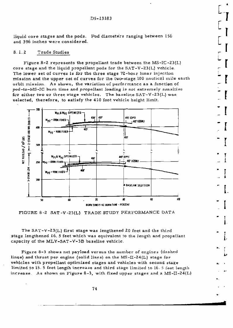
D5-13183
l iquid c o r e s t a g e s and the p o d s . Pod d i a m e t e r s ranging be tween 156 and 396 i n c h e s w e r e c o n s i d e r e d .
8. 1.2 T r a d e S tud ies
F i g u r e 8-2 r e p r e s e n t s the p rope l l an t t r a d e be tween the MS- IC-23(L) c o r e s t a g e and the l iquid p r o p e l l a n t pods for the SAT-V-23(L.) veh i c l e . The l o w e r se t of c u r v e s i s for the t h r e e s t a g e 72-ho.ur l u n a r in jec t ion m i s s i o n and the u p p e r s e t of c u r v e s for the two-s tage 100 nau t i ca l m i l e e a r t h o r b i t m i s s i o n . As shown, t he v a r i a t i o n of p e r f o r m a n c e a s a function of p o d - t o - M S - I C b u r n t i m e and p r o p e l l a n t load ing i s not e x t r e m e l y s e n s i t i v e fcr e i t h e r two o r t h r e e s t a g e v e h i c l e s . The b a s e l i n e SAT-V-23(1_) w a s se l ec t ed , there fore , , to s a t i s fy the 410 foot vehic le height l i m i t .
SO
3 3 i 3 »
Wp l4Wpz0PnMIZfD
Wp? - BOOK FIXED
Wpj -WKFI t fO
1 41?
«r
T •HO" I0PTI
30 60 70 8URNTIW/5-IC BURN TIM -PERCENT
FIGURE 8-2 SAT-V-23 (L) TRADE STUDY P E R F O R M A N C E DATA
The S A T - V - 2 3 ( L ) f i r s t s t a g e w a s lengthened 20 feet and the t h i r d s t a g e l eng thened I D . 5 fee t w h i c h w a s equivalent to the length and p rope l l an t capac i ty of t he M L V - S A T - V - 3 B b a s e l i n e veh ic le .
F i g u r e 8-3 shows net pay load v e r s u s the n u m b e r of eng ines (dashed l ings) and t h r u s t p e r engine (sol id l ines) on the MS-I I -24(L) s t a g e for v e h i c l e s wi th p r o p e l l a n t o p t i m i z e d s t a g e s and veh i c l e s wi th second s t age l i m i t e d to 15. 5 feet l eng th i n c r e a s e and t h i r d s tage l i m i t e d to 16- 5 feet length i n c r e a s e . A s shown on F i g u r e 8 - 3 , with fixed u p p e r s t a g e s and a MS-II -24(L)
74
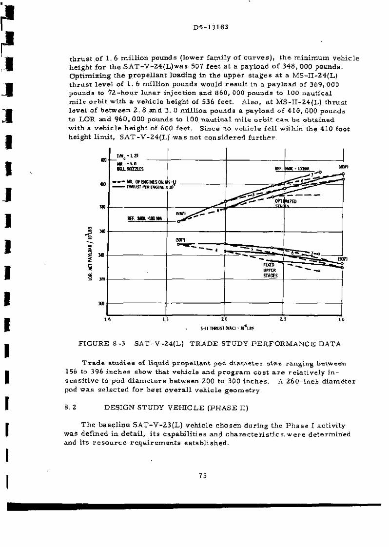
D5-13183
t h r u s t of 1.6 mi l l i on pounds ( lower fami ly of c u r v e s ) , the m i n i m u m veh ic le he ight for t he S A T - V - 2 4 ( L ) w a s 507 feet a t a pay load of 348, 000 pounds . Op t imiz ing t he p r o p e l l a n t load ing in the u p p e r s t a g e s a t a MS-II -24(L) t h r u s t l eve l of 1. 6 mi l l ion pounds would r e s u l t in a p a y l o a d of 369, 000 pounds to 7 2 - h o u r luna r in jec t ion and 860, 000 pounds to 100 nau t i ca l m i l e o r b i t wi th a veh ic le he ight of 536 feet . Also , a t MS-I I -24(L) t h r u s t l eve l of b e t w e e n 2. 8 and 3. 0 mi l l ion pounds a pay load of 410, 000 pounds to LOR and 9&0t 000 pounds to 100 n a u t i c a l m i l e o r b i t c a n be ob ta ined wi th a veh i c l e he igh t of 600 feet . S ince no veh ic le fel l wi thin the 410 foot height l im i t , S A T - V - 2 4 ( L ) w a s not c o n s i d e r e d f u r t h e r .
(tart
i»n
S-l I THRUST (VAC) - HTLB5
FIGURE 8-3 SAT-V-24(L) TRADE STUDY P E R F O R M A N C E DATA
T r a d e s t u d i e s of l iquid p r o p e l l a n t pod d i a m e t e r s i z e r ang ing be tween 156 to 396 i n c h e s show that veh i c l e and p r o g r a m cos t a r e r e l a t i v e l y i n s e n s i t i v e to pod d i a m e t e r s be tween ZOO to 300 i n c h e s . A 2 6 0 - i n c h d i a m e t e r pod w a s s e l e c t e d for be s t o v e r a l l veh ic le g e o m e t r y .
8 . 2 DESIGN STUDY VEHICLE (PHASE II)
The b a s e l i n e SAT-V-23(L) vehic le chosen dur ing the P h a s e I ac t iv i ty w a s def ined in de t a i l , i t s c a p a b i l i t i e s and c h a r a c t e r i s t i c s w e r e d e t e r m i n e d and i t s r e s o u r c e r e q u i r e m e n t s e s t a b l i s h e d .
75
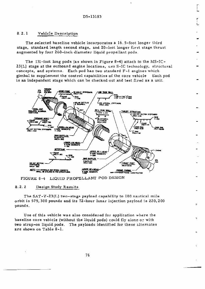
D5-13183
8 .2 .1 Vehicle Description
The .selected basel ine vehicle incorporates a 16. 5-foot longer third stage, s tandard length second stage, and 20-foot longer f i rs t stage thrust augmented by four 260-inch diameter liquid propellant pods.
The 131-foot long pods (as shown in Figure 8-4) attach to the MS-IC-Z3(L) stage at the outboard engine locations, use S-IC technology, s t ructura l concepts, and sys tems. Each pod has two standard F - l engines which gimbal to supplement the control capabilities of the core vehicle Each pod i s an independent stage which can be checked out and test fired as a unit.
FIGURE 8-4 LIQUID PROPELLANT POD DESIGN
8.2.Z Design Study Resul ts
The SAT-V-23(L) two-stage payload capability to 100 nautical mile orbit is 579, 300 pounds and its 72-hour lunar injection payload is 220,200 pound s,
Use of this vehicle was also considered for application where the baseline core vehicle (without the liquid pods) could fly alone or with two strap-on liquid pods. The payloads identified for these a l ternates a r e shown on Table 8 -1 .
76
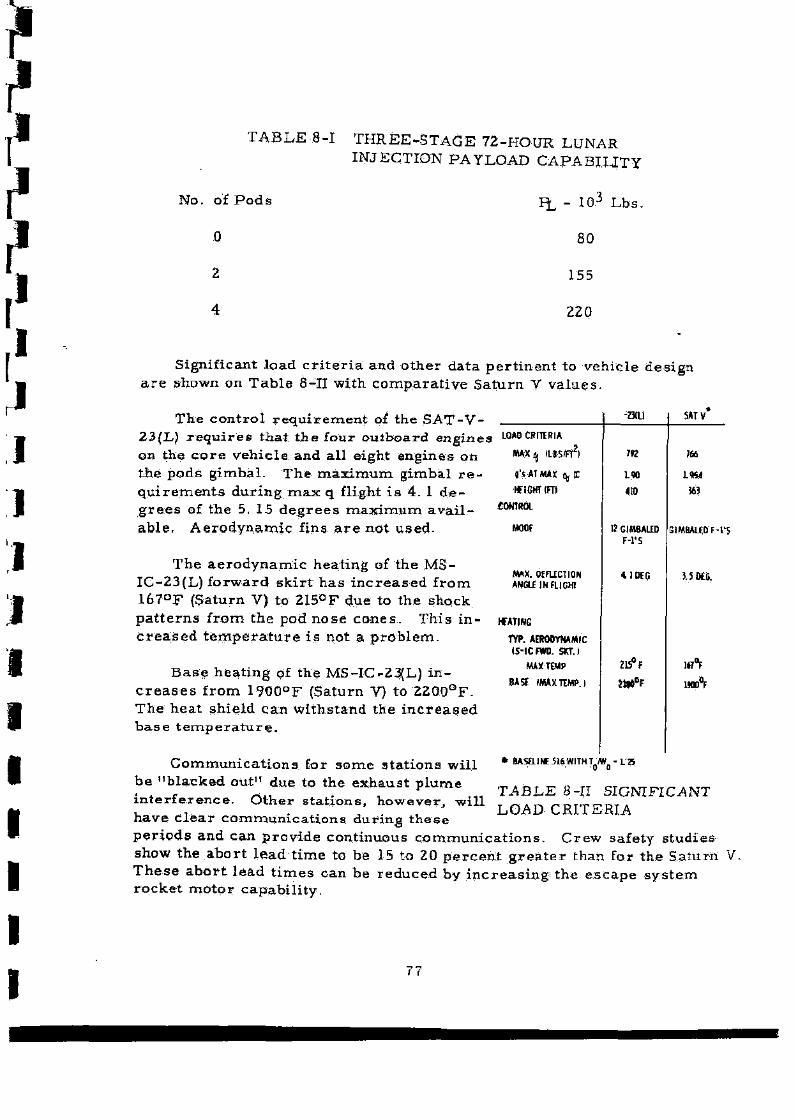
T A B L E 8-1 T H R E E - S T A G E 72-HOUR LUNAR INJECTION PAYLOAD CAPABILITY
No. of P o d s
0
p£, - 10 J L b s .
80
155
220
Signif icant load c r i t e r i a and o t h e r da t a p e r t i n e n t to veh i c l e des ign a r e shown on T a b l e 8-H wi th c o m p a r a t i v e S a t u r n V v a l u e s .
The c o n t r o l r e q u i r e m e n t of the S A T - V -23{L) r e q u i r e s t h a t t h e four ou tboa rd eng ines LQADCRITIRIA
on the c o r e veh i c l e and al l e ight engines on the p o d s g imba l . The m a x i m u m gxmbal r e q u i r e m e n t s d u r i n g m a x q flight i s 4. 1 d e g r e e s of the 5. 15 d e g r e e s m a x i m u m a v a i l ab l e . A e r o d y n a m i c fins a r e no t u sed .
MAX^ OS/FT2)
g'sATMAX HjC
WIGHT (FTI
£0NTHCH
MOW
The a e r o d y n a m i c heat ing of the M S -IC-23(L) f o r w a r d s k i r t h a s i n c r e a s e d f r o m 1 6 7 ° F {Saturn V) to 215°F due to the shock p a t t e r n s f r o m t h e pod n o s e c o n e s . Th i s i n c r e a s e d t e m p e r a t u r e i s not a p r o b l e m .
B a s e h e a t i n g of the MS-IC-23(L) i n c r e a s e s f r o m 1900°F (Saturn V) to 2 2 0 0 ° F . The hea t sh i e ld can wi ths tand the i n c r e a s e d b a s e t e m p e r a t u r e .
C o m m u n i c a t i o n s for s o m e s t a t ions wi l l be "b l acked ou t" due to the exhaus t p l u m e i n t e r f e r e n c e . O t h e r s t a t i ons , howeve r , w i l l
MAX. QEFUTTIQN ANGU1NFLIGH1
WATINC
TYP. AERODYNAMIC IS-iCRM). SXT.I
MAX TEMP
BASE IMAXTW.J
-mi
792
L90
410
12GIMBALED F-1'S
41 KG
Z15°f
*BAStLIWS16WITHT.yw -LZ5 • 0 o
MTV
m
G1MBALE0 F-l'S
J.5M6.
1«°F
Waft
T A B L E 8-II SIGNIFICANT LOAD CRITERIA
have c l e a r c o m m u n i c a t i o n s du r ing t h e s e p e r i o d s and can p r o v i d e cont inuous c o m m u n i c a t i o n s . C r e w safety s tud ies show the a b o r t l ead t ime to be 15 to 20 p e r c e n t g r e a t e r than for t he Sa tu rn V. T h e s e a b o r t l ead t i m e s can be r e d u c e d by i n c r e a s i n g t he e s c a p e s y s t e m r o c k e t m o t o r capab i l i t y .
77
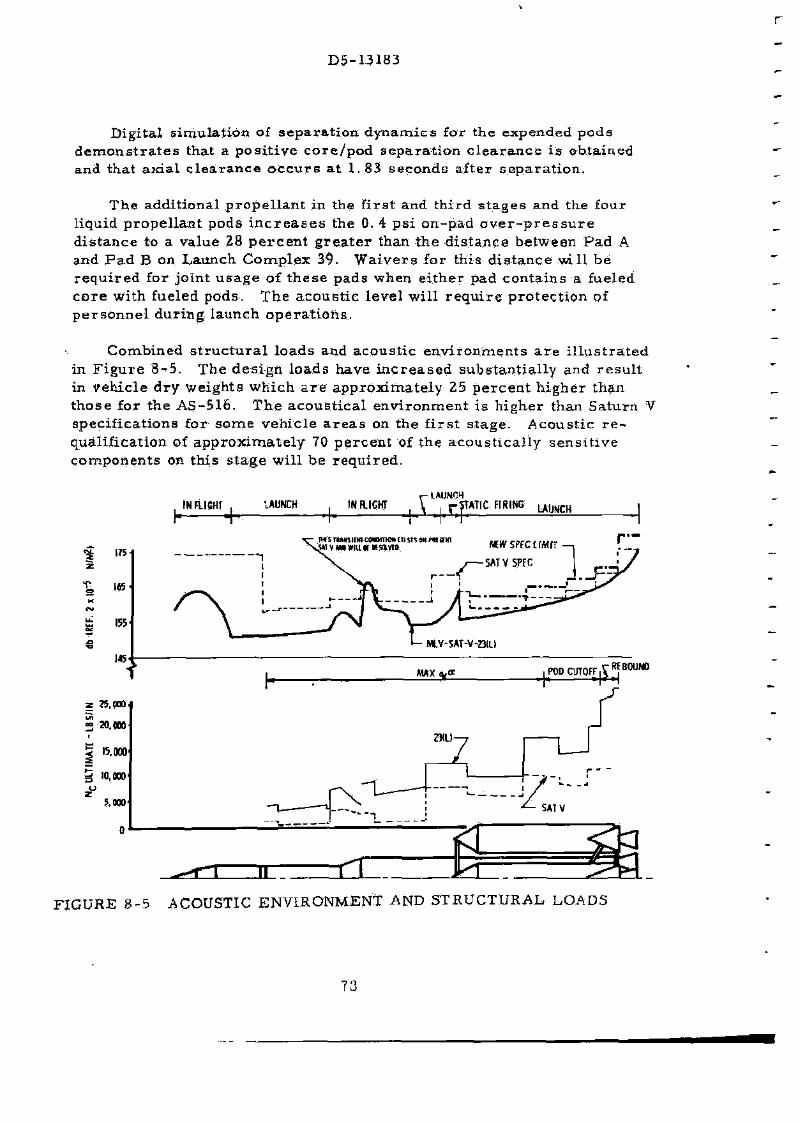
D 5 - U 1 B 3
Digi ta l s imula t ion of s e p a r a t i o n d y n a m i c s for the expended pods d e m o n s t r a t e s tha t a p o s i t i v e c o r e / p o d s e p a r a t i o n c l e a r a n c e i s ob ta ined and tha t a x i a l c l e a r a n c e o c c u r s a t 1. 83 seconds af ter s e p a r a t i o n .
T h e addi t ional p r o p e l l a n t in the f i r s t and th i rd s t a g e s and the four l iquid p r o p e l l a n t pods i n c r e a s e s the 0. 4 p s i on-p.ad o v e r - p r e s s u r e d i s t a n c e to a value 28 p e r c e n t g r e a t e r than t he d i s t a n c e be tween P a d A and P a d B on Launch C o m p l e x 39. W a i v e r s for this d i s t a n c e m i l be r e q u i r e d for jo in t u s a g e of t h e s e pads when e i t h e r pad con ta ins a fueled c o r e wi th fueled pods . T h e a c o u s t i c l eve l wi l l r e q u i r e p r o t e c t i o n of p e r s o n n e l du r ing launch o p e r a t i o n s .
Combined s t r u c t u r a l l o a d s and acous t i c e n v i r o n m e n t s a r e i l l u s t r a t e d in F i g u r e 8 -5 . The d e s i g n loads have i n c r e a s e d subs t an t i a l l y and r e s u l t in veh i c l e d r y weigh t s wh ich a r e a p p r o x i m a t e l y 25 p e r c e n t h i g h e r than t h o s e for the AS-516. T h e a c o u s t i c a l e n v i r o n m e n t i s h ighe r than Sa tu rn V spec i f i ca t ions for s o m e v e h i c l e a r e a s on the f i r s t s t age . Acous t i c r e -qual i f ica t ion of a p p r o x i m a t e l y 70 p e r c e n t of the a c o u s t i c a l l y s e n s i t i v e c o m p o n e n t s on th i s s t a g e wi l l be r e q u i r e d .
JHFLICttT^ UUHCH INFLIGHT r LAUNCH
A J,r.flATIC F""NC mam
THIS TUMSIEH UMM1HM EliSIl ON P« SKI MVM»WIUftKSU». NEWSPECLIMIT
5ATVSPEC
r—
FIGURE 8-5 ACOUSTIC ENVIRONMENT AND STRUCTURAL. LOADS
73
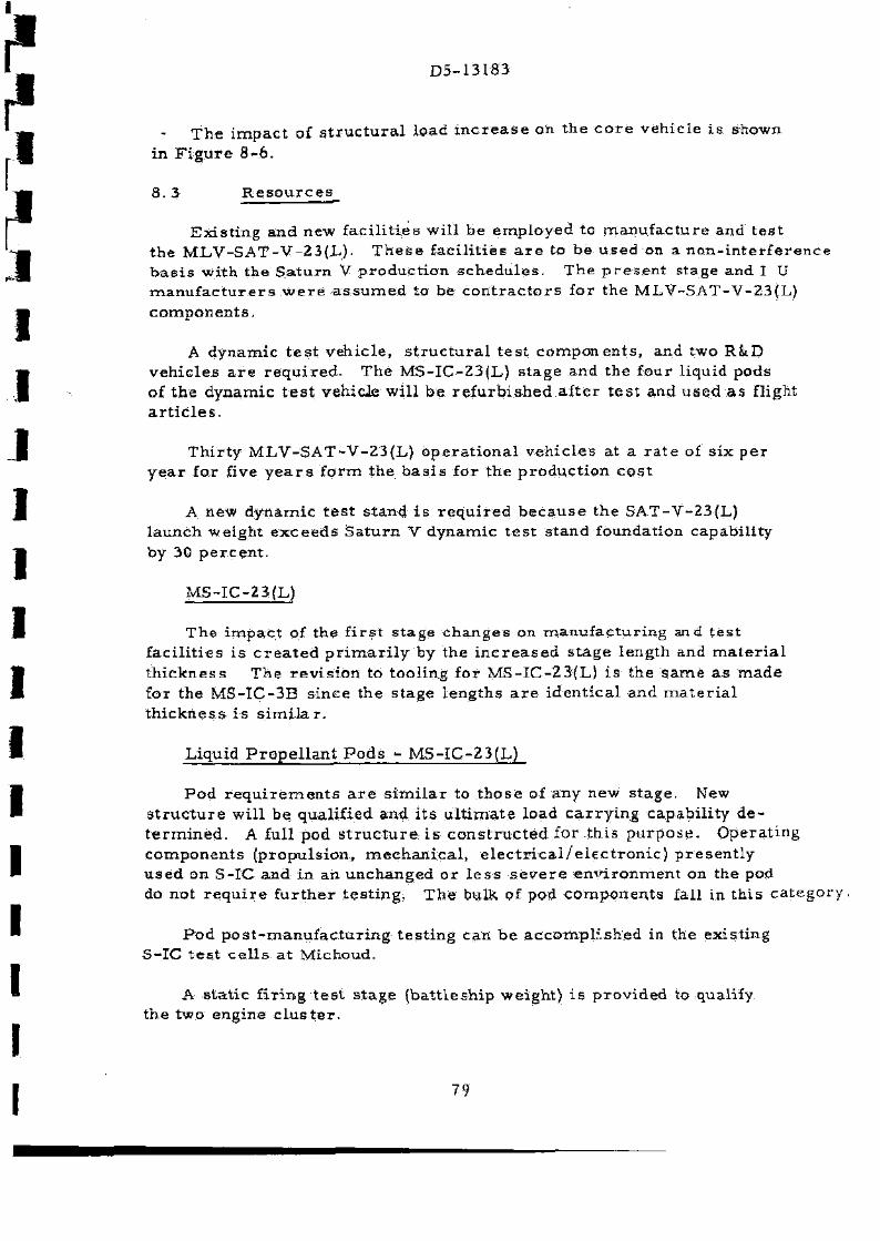
D 5 - 1 3 I 8 3
T h e i m p a c t of s t r u c t u r a l load i n c r e a s e on the c o r e vehic le i s shown in F i g u r e 8-6 .
8. 3 R e s o u r c e g_
Ex i s t i ng and new fac i l i t i e s wi l l be employed to m a n u f a c t u r e and t e s t the M L V - S A T - V - 2 3 ( L ) . T h e s e fac i l i t i es a r e to be u sed on a n o n - i n t e r f e r e n c e b a s i s wi th the S a t u r n V p roduc t i on s c h e d u l e s . The p r e s e n t s tage and I U m a n u f a c t u r e r s w e r e a s s u m e d to be c o n t r a c t o r s for the M L V - S A T - V - 2 3 ( L ) c o m p o n e n t s .
A dynamic t e s t veh ic l e , s t r u c t u r a l t e s t c o m p o n e n t s , and two R&D v e h i c l e s a r e r e q u i r e d - The MS-IC-Z3(L.) s t age and the four l iquid pods of t he dynamic t e s t vehicle wi l l be r e f u r b i s h e d a f t e r t e s t and used a s flight a r t i c l e s .
T h i r t y M L V - S A T - V - 2 3 ( L ) o p e r a t i o n a l v e h i c l e s at a r a t e of s ix p e r y e a r for five y e a r s f o r m the b a s i s for t he p r o d u c t i o n c o s t
A new dynamic t e s t s tand i s r e q u i r e d b e c a u s e the SAT-V-23(L) l aunch we igh t e x c e e d s Sa tu rn V dynamic t e s t s tand foundation capabi l i ty by 30 p e r c e n t .
MS- IC-23(L)
The i m p a c t of the f i r s t s t age changes on m a n u f a c t u r i n g and t e s t f ac i l i t i e s i s c r e a t e d p r i m a r i l y by the i n c r e a s e d s t a g e length and m a t e r i a l t h i c k n e s s The r e v i s i o n to tool ing for MS- IC-23(L) i s the s a m e a s m a d e for the M S - I C - 3 B s ince the s tage lengths a r e i d e n t i c a l and m a t e r i a l t h i c k n e s s i s s i m i l a r .
Liquid P r o p e l l a n t P o d s - MS- IC-23(L)
P o d r e q u i r e m e n t s a r e s i m i l a r to t h o s e of any new s tage . New s t r u c t u r e wil l be qual i f ied and i t s u l t i m a t e load c a r r y i n g capabi l i ty d e t e r m i n e d . A full pod s t r u c t u r e i s c o n s t r u c t e d for t h i s p u r p o s e . Opera t ing componen t s (p ropu l s ion , m e c h a n i c a l , e l e c t r i c a l / e l e c t r o n i c ) p r e s e n t l y u s e d on S-IC and in an unchanged o r l e s s s e v e r e e m d r o n m e n t on the pod do not r e q u i r e f u r t h e r t e s t i ng . T h e bulk pf pod cornponents fall in th i s c a t e g o r
P o d p o s t - m a n u f a c t u r i n g t e s t i n g can b e a c c o m p l i s h e d in the exis t ing S- IC t e s t c e l l s a t Michoud.
A s t a t i c f i r i ng t e s t s t age (ba t t l e sh ip weight ) i s p r o v i d e d to qualify the two engine c l u s t e r .
79
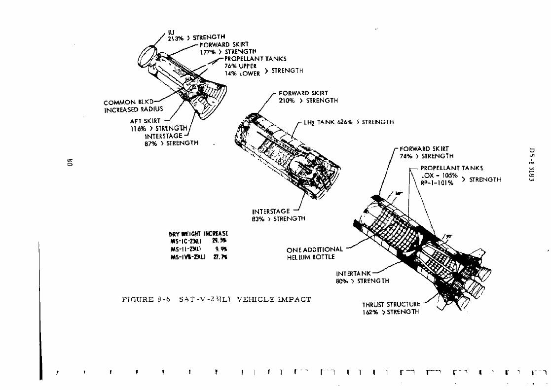
2 1 3 * > STRENGTH FORWARD SKIRT 177% > STRENGTH
PROPELLANT TANKS 76% UPPER U % LOWER > STRENGTH
COMMON BLKD INCREASED RADIUS
AFT SKIRT 116% > STRENGTH,
INTERSTAGE' 87% > STRENGTH
DRY WEIGHT INCRMSE *5-IC-»l) » • » MS-II-2XU 9.9* MS-IV1-SIL) 27.7*
FORWARD SKIRT 210% > STRENGTH
LH2 TANK 626% > STRENGTH
INTERSTAGE 83% > STRENGTH
ONEADDITIONAL HELIUM BOTTLE
FIGURE 8-6 SAT-V-Z3(L) VEHICLE IMPACT
INTERTANK 80% •) STRENGTH
THRUST ST 162% > ST
I 1 r—i r -i
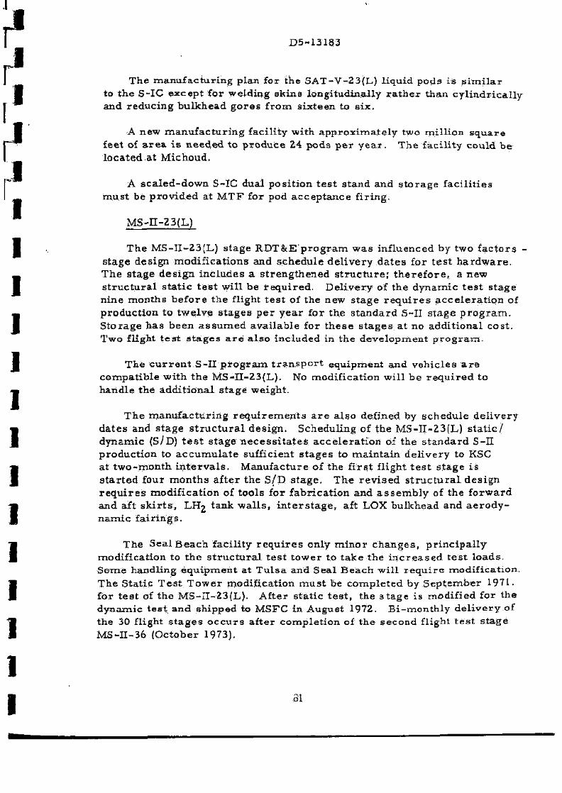
D5-13183
The m a n u f a c t u r i n g plan for the SAT-V-23{L) l iquid pods i s s i m i l a r to t he S-IC e x c e p t for welding s k i n s longi tudina l ly r a t h e r than c y l i n d r i c a l l y and r educ ing bu lkhead g o r e s f r o m s ix teen to s ix .
A new m a n u f a c t u r i n g faci l i ty wi th a p p r o x i m a t e l y two mi l l ion s q u a r e feet of a r e a i s n e e d e d to p r o d u c e 24 pods p e r y e a r . The fac i l i ty cou ld b e l oca t ed a t Michoud,
A s c a l e d - d o w n S-IC dual pos i t ion t e s t s tand and s t o r a g e f ac i l i t i e s m u s t be p r o v i d e d at M T F for pod a c c e p t a n c e f i r ing .
M S - n - Z 3 ( L )
The MS- I I -23 (L) s tage R D T & E p r o g r a m w a s inf luenced by two f a c t o r s -s t age des ign mod i f i ca t i ons and s c h e d u l e d e l i v e r y d a t e s for t e s t h a r d w a r e . T h e s t age d e s i g n i n c l u d e s a s t r e n g t h e n e d s t r u c t u r e ; t h e r e f o r e , a new s t r u c t u r a l s t a t i c t e s t wi l l be r e q u i r e d . D e l i v e r y of the dynamic t e s t s t age n i n e m o n t h s b e f o r e t he flight t e s t of the new s t a g e r e q u i r e s a c c e l e r a t i o n of p roduc t ion to twe lve s t a g e s p e r y e a r for the s t a n d a r d S-II s t a g e p r o g r a m . S t o r a g e h a s b e e n a s s u m e d ava i l ab l e for t h e s e s t a g e s a t no add i t iona l cos t . Two flight t e s t s t a g e s a r e a l s o inc luded in the d e v e l o p m e n t p r o g r a m -
The c u r r e n t . S - I I p r o g r a m t r a n s p o r t equ ipment and veh i c l e s a r e compa t ib l e wi th t he M S - n - 2 3 ( L ) . No modif ica t ion wil l be r e q u i r e d to handle the a d d i t i o n a l s t age weight .
T h e m a n u f a c t u r i n g r e q u i r e m e n t s a r e a l so defined by s c h e d u l e d e l i v e r y d a t e s and s t age s t r u c t u r a l des ign . Schedul ing of the MS- I I -23 (L) s t a t i c / d y n a m i c (S/D) t e s t s t age n e c e s s i t a t e s a c c e l e r a t i o n of the s t a n d a r d S-II p roduc t ion to a c c u m u l a t e sufficient s t a g e s to m a i n t a i n d e l i v e r y to KSC at t w o - m o n t h i n t e r v a l s . Manufac tu re of the f i r s t f l ight t e s t s t age i s s t a r t e d four m o n t h s a f te r the S /D s t a g e . T h e r e v i s e d s t r u c t u r a l de s ign r e q u i r e s modi f ica t ion of tools for f ab r i ca t i on and a s s e m b l y of the f o r w a r d and aft s k i r t s , Lrlg tank w a l l s , i n t e r s t a g e , aft LOX bu lkhead and a e r o d y n a m i c f a i r i n g s .
The Seal B e a c h fac i l i ty r e q u i r e s only m i n o r c h a n g e s , p r i n c i p a l l y modi f ica t ion to t he s t r u c t u r a l t e s t t o w e r to t a k e the i n c r e a s e d t e s t l o a d s . S o m e handl ing e q u i p m e n t a t T u l s a and Sea l B e a c h wi l l r e q u i r e modif ica t ion . The S ta t i c T e s t T o w e r modif ica t ion m u s t be c o m p l e t e d by S e p t e m b e r 1971. for t e s t of t he M S - I I - 2 3 ( L ) . Af ter s t a t i c t e s t , the s t a g e i s modif ied for the d y n a m i c t e s t and shipped to MSFC in Augus t 1972. B i - m o n t h l y d e l i v e r y of the 30 flight s t a g e s o c c u r s af ter comple t ion of the second flight t e s t s t age MS-I I -36 {October 1973).
31
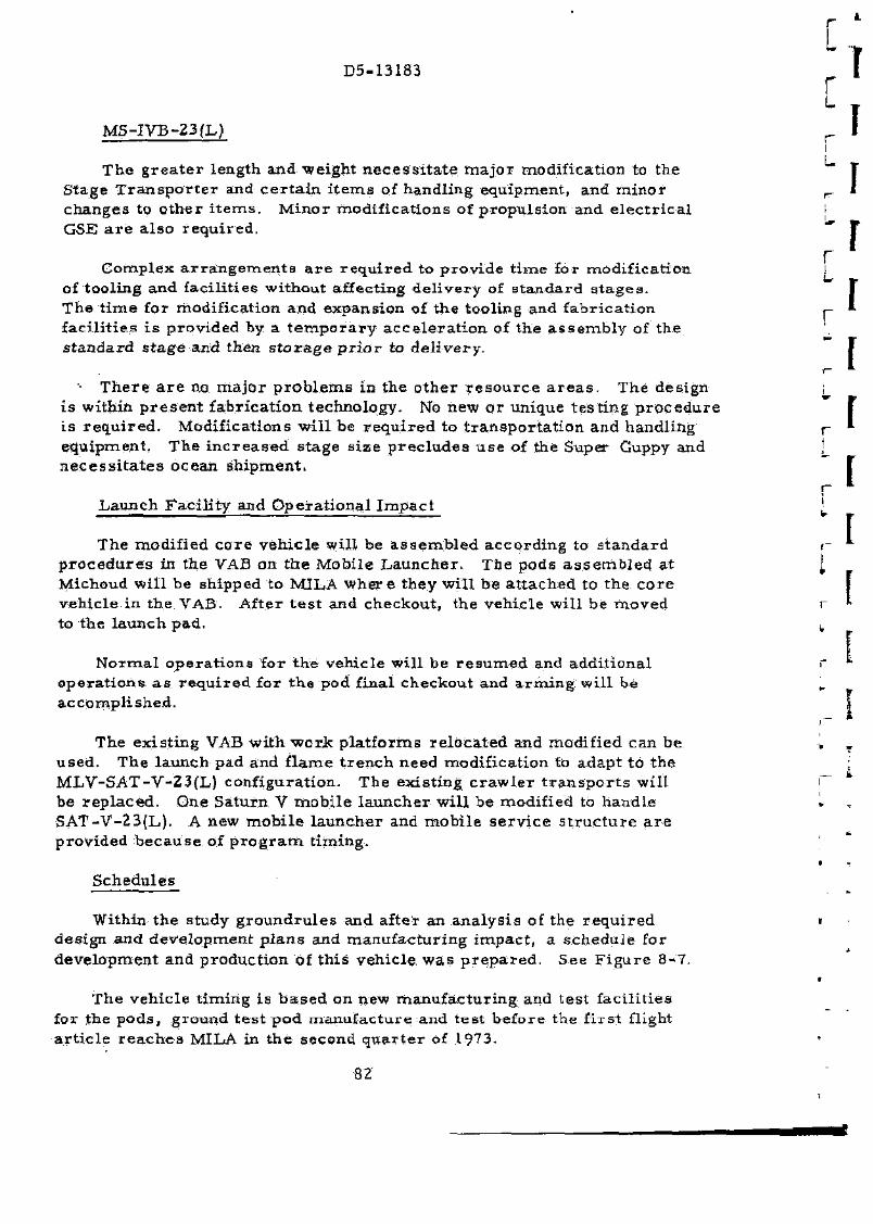
D5-13183
M S - I V B - 2 3 ( L )
T h e g r e a t e r length and we igh t n e c e s s i t a t e m a j o r modif ica t ion to the S tage T r a n s p o r t e r and c e r t a i n i t e m s of handl ing equipment , and m i n o r changes to o t h e r i t e m s . M i n o r mod i f i ca t ions of p ropu l s ion and e l e c t r i c a l GSE a r e a l s o r e q u i r e d .
C o m p l e x a r r a n g e m e n t s a r e r e q u i r e d to p r o v i d e t i m e for modi f ica t ion of tool ing and fac i l i t i e s wi thout affect ing d e l i v e r y of s t a n d a r d s t a g e s -The t i m e for modi f ica t ion and expans ion of t he tool ing and f ab r i ca t i on f ac i l i t i e s i s p rov ided by a t e m p o r a r y a c c e l e r a t i o n of the a s s e m b l y of the s t a n d a r d s t a g e and then s t o r a g e p r i o r to d e l i v e r y .
T h e r e a r e no m a j o r p r o b l e m s in the o t h e r r e s o u r c e a r e a s . The des ign i s wi tbin p r e s e n t f a b r i c a t i o n t echnology . No new o r unique t e s t i n g p r o c e d u r e i s r e q u i r e d . Modif ica t ions w i l l be r e q u i r e d to t r a n s p o r t a t i o n and handl ing equipment , T h e i n c r e a s e d s t age s i z e p r e c l u d e s u s e of the Super Guppy and n e c e s s i t a t e s ocean sh ipmen t .
L a u n c h F a c i l i t y and O p e r a t i o n a l I m p a c t
The modif ied c o r e v e h i c l e wil l be a s s e m b l e d a c c o r d i n g to s t a n d a r d p r o c e d u r e s in t he VAB on t h e Mob i l e L a u n c h e r . T h e pods a s s e m b l e d a t Michoud wi l l be shipped to MILA w h e r e they wi l l be a t t a c h e d to the c o r e veh i c l e in the VAB. Af ter t e s t and checkout , the veh ic le wil l be m o v e d to the l aunch pad .
N o r m a l o p e r a t i o n s for t h e vehic le wi l l be r e s u m e d and add i t iona l o p e r a t i o n s a s r e q u i r e d for t he pod f inal checkout and a r m i n g wi l l be a c c o m p l i s h e d .
The ex i s t ing VAB wi th worjs p l a t f o r m s r e l o c a t e d and modif ied can be used . The l aunch pad and f l a m e t r e n c h need modi f ica t ion to adap t to the M L V - S A T - V - 2 3 { L ) conf igura t ion . The ex i s t ing c r a w l e r t r a n s p o r t s w i l l be r e p l a c e d . One Sa turn V m o b i l e l a u n c h e r wi l l be modif ied to hand le S A T - V - 2 3 ( L ) . A new m o b i l e l a u n c h e r and m o b i l e s e r v i c e s t r u c t u r e a r e p rov ided b e c a u s e of p r o g r a m t im ing .
S c h e d u l e s
Within t he study g r o u n d r u l e s and af ter an a n a l y s i s of the r e q u i r e d des ign and d e v e l o p m e n t p l a n s and m a n u f a c t u r i n g i m p a c t , a s c h e d u l e for deve lopmen t and p roduc t i on of t h i s veh ic le w a s p r e p a r e d . See F i g u r e 8-7.
The veh ic l e t i m i n g is b a s e d on new m a n u f a c t u r i n g and t e s t f ac i l i t i e s for the p o d s , g round t e s t p o d m a n u f a c t u r e and t e s t be fo re the f i r s t flight a r t i c l e r e a c h e s MILA in t h e second q u a r t e r of 1973.
82
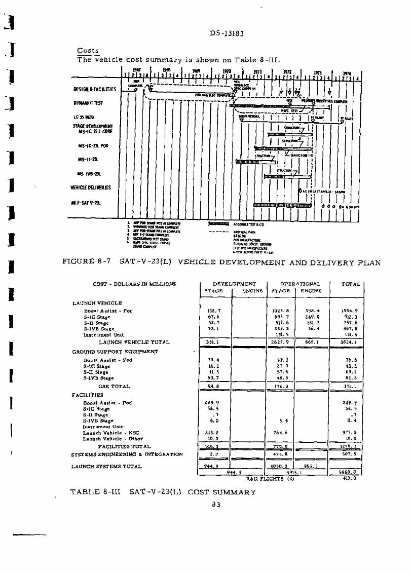
D5-13183
C o s t s The veh ic le cos t s u m m a r y is shown on Tab l e 8-II1.
DESIGN * FACILITIES
DYNAMIC TEST
LC3SM0D
STACE DEVaoPMENT MS-IC-2UC0RE
MS-IC-a POO
Ms-u-a
MS-tVS-HL
VEHICLE DB.IVESIE5
mv-SATV-a .
1OT
l MFntlMMMjiicawuii
\ arnmamniwiiii * •Ti-isuvcanwtm *ssa«iiiiTicn CMTICM.MIM
UVM "»*UltJf>CT«K SUIUINtCdKST MOUW ira mp tuimrtniKu in s r jfrturamm nicm
4 * » ft t n w i
mil
FIGURE 8-7 SAT-V-23{L) VEHICLE D E V E L O P M E N T AND DELIVERY PLAN
COST - D O L L A R S IN MILLIONS
L A U N C H V E H I C L E
Bops t ASSiat - Pod 5 - l C S tage S-II Stage S-IVB S tage I n s t r u m e n t Un i t
LAUNCH V E H I d L E T O T A L
GROUND S U P P O R T E Q U I P M E N T
Boost A s s i s t - Pod
5 - I C S t a g s
S-II Staga
S-IVB S tage
GSE T O T A L
F A C I L I T I E S
B o o s t A s s i s t - Pod S-IC S tags 5 - I I S t a g e S-IVB S tage I n s t r u m e n t Unit L a u n c h Vehic le - KSC L a u n c h Veh ic l e - O t h e r
F A C I L I T I E S T O T A L
SYSTEMS ENGINEERING 1 INTEGRATION
LAUNCH SYSTEMS T O T A L
D E V E L O P M E N T O P E R A T I O N A L T O T A L STAGE ENGINE S T A G E ENGINE
132. T 1023. 8 3 9 8 . 4 1554.9 6 7 . 6 5 9 5 . 7 2 4 9 . 0 912.3 52. 7 .517.6 161.3 757 .6 72. 1 5 5 9 . 3
131.5 3 6 . 4 4 6 7 . 8
131.5
331.1 2 6 2 7 . 9
4 3 . 2
865.1 3824. L
7 6 . 6 3 3 . 4
2 6 2 7 . 9
4 3 . 2
865.1 3824. L
7 6 . 6 16. 2 2 7 . 0 4 3 , 2 11. 5 5 7 . 6 69 .1
S3. 7 48 . 5 8 2 . 2
94. 8 176 .3 371.1
2 2 9 . 9 2 2 9 . 9 54. 3 56. 5
. 7 . 7 6 . 0 5 .4 11.4
213 .2 7 6 4 . 6 9 7 7 . 8 10.0 10.0
2.7
7 7 0 . 0
4 7 5 . 8
1276.3
2.7
7 7 0 . 0
4 7 5 . 8 5 0 7 . 5
9 4 4 , 9 4O5Q.0 9i,iA 9 4 4 . 9 4915.1 SS6Q.0
R ( . D F L I G H T S (2) 413.0
T A B L E 8-III SAT-V-23{L) COST SUMMARY
33

D5-13183
9- 0 CONCLUSIONS AND RECOMMENDATIONS
All the l aunch veh i c l e s s tudied under the NAS8 -20266 s tudy c o n t r a c t a r e f ea s ib l e conf igura t ions and candida tes for p a y l o a d s r ang ing f rom 78, 000 pounds to 960 ,000 pounds to a 100 n a u t i c a l m i l e E a r t h o rb i t .
Specif ic b a s e l i n e veh i c l e s s tudied within fac i l i ty l i m i t a t i o n ground r u l e s w e r e l i m i t e d to a m a x i m u m payload of 579, 000 pounds to a 100 nau t i ca l m i l e E a r t h o r b i t .
9.1 I N T E R M E D I A T E PAYLOAD LAUNCH V E H I C L E S
F r o m t h e s e s t u d i e s , i t w a s concluded tha t a l l the i n t e r m e d i a t e launch v e h i c l e s w e r e f e a s i b l e us ing ex i s t ing Sa tu rn V Stages with m i n i m u m m o d i f i c a t i o n s . T h e s e eight l aunch veh i c l e s wi l l c o v e r an i n c r e m e n t a l payload r a n g e f r o m 78, 000 pounds to 255, 000 pounds in low E a r t h o rb i t . No m a j o r s t r u c t u r a l or o the r s y s t e m changes a r e r e q u i r e d to the ex i s t ing Sa tu rn V s t a g e s to obtain t h i s family of flexible l aunch v e h i c l e s .
T h e r e f o r e , it i s r e c o m m e n d e d that in the s e l e c t i o n of the i n t e r m e d i a t e payload Vehicles t ha t both cost e f fec t iveness and f lex ib i l i ty be cons ide red -In the u t i l i za t ion of ex i s t ing Sa tu rn V s t a g e s for i n t e r m e d i a t e payload app l i ca t i on , a l l p o s s i b l e a r r a n g e m e n t s should b e i m p l e m e n t e d s i m u l t a n e o u s l y to obta in t h i s f lexibi l i ty . It i s f u r t h e r conc luded tha t a l l Uprated Sa tu rn V v e h i c l e s a l so have i n t e r m e d i a t e d e r i v a t i v e s . In o t h e r w o r d s , when a n u p r a t e d veh ic le i s chosen for d e v e l o p m e n t , c o n s i d e r a t i o n should be g iven to developing s i m u l t a n e o u s l y i t s i n t e r m e d i a t e payload c a p a b i l i t i e s .
9-2 U P R A T E D SATURN V LAUNCH VEHICLES
T h e u p r a t e d v e h i c l e s defined in the t r a d e s tudy and s tud ied in d e t a i l in P h a s e II a r e f e a s i b l e conf igura t ions and log ica l c a n d i d a t e s for payloads in e x c e s s of the c u r r e n t Sa tu rn V capab i l i ty . No m a j o r p r o b l e m a r e a s w e r e ident i f ied for e i t h e r deve lopment or p roduc t i on . No s ignif icant a d v e r s e flight e n v i r o n m e n t a l c h a r a c t e r i s t i c s w e r e ident i f ied .
M a j o r veh ic le mod i f i ca t ions to adapt the S a t u r n V vehic le to t h e s e new u p r a t e d con f igu ra t ions w e r e defined a s fo l lows .
a . S t r u c t u r a l modi f ica t ion of a l l s t a g e s to enable the vehic le to w i ths t and the h i g h e r l o a d s imposed due to the l a r g e r payload capabi l i ty and i n c r e a s e d p a y l o a d envelope ( i n c r e a s e d pay load d i a m e t e r and 410 foot vehic le he ight ) .
3 5
D5-13183
b . S t r u c t u r a l mod i f i c a t i on of s o m e s t a g e s for i n c r e a s e d t a n k l eng ths and i n c r e a s e d engine t h r u s t .
c . Se l ec t ive r equa l i f i ca t i on of t he a c o u s t i c a l l y s ens i t i ve componen t s to qualify t h e s e c o m p o n e n t s for the i n c r e a s e d a c o u s t i c a l env i ronmen t -
G e n e r a l c o m p a r a t i v e conc lus ions a r r i v e d at f r o m the NAS8-20266 s tud ie s a r e a s fo l lows.
T h e S A T - V - 3 B l a u n c h veh ic le h a s the b e s t payload to l aunch weight of a l l the u p r a t e d v e h i c l e s s tud ied . The S A T - V - 3 B has the m i n i m u m launch i m p a c t of a l l the u p r a t e d launch v e h i c l e s s tud ied . On the o ther hand , t h i s veh i c l e r e q u i r e s the m o s t r e s e a r c h and d e v e l o p m e n t cos t p e r pound of payload, and r e q u i r e s the m o s t l ead t i m e of a l l u p r a t e d launch v e h i c l e s s tudied-
The SAT-V-4(S)B l a u n c h veh ic le has the b e s t payload pe r r e s e a r c h and deve lopmen t d o l l a r w i t h a nomina l launch i m p a c t . However , a s shown on F i g u r e s 2 -3 and 2 - 4 , when o p e r a t i o n c o s t s a r e inc luded , the SAT-V-4(S)B does not b e c o m e the m o s t cost effect ive launch v e h i c l e . It r e q u i r e s the l e a s t l ead t i m e and deve lopmen t cos t of a l l the u p r a t e d l aunch v e h i c l e s .
Of a l l the u p r a t e d l a u n c h veh i c l e s s tud ied under the NAS8-20266 c o n t r a c t , the SAT-V-25(S) l aunch veh ic le i s the m o s t cos t effect ive ( s l ight ly ahead of SAT -V-23(Iv)) . The SAT-V-25(S) v e h i c l e , when c o m p a r e d to the SAT-V-4 (S )B v e h i c l e , does cos t m o r e to deve lop and h a s a g r e a t e r i m p a c t a t the l aunch fac i l i ty .
T h e S A T - V - 2 3 ( L ) l aunch vehic le h a s the g r e a t e s t payload capab i l i ty of a l l the launch v e h i c l e s s tud ied and is a l m o s t a s cos t effective a s the S A T - V - 2 5 ( S ) . I t a l s o h a s the advan tage of us ing ex i s t ing s t a n d a r d S a t u r n V e n g i n e s , p r o p e l l a n t s , and s y s t e m s , t t d o e s , h o w e v e r , have the g r e a t e s t i m p a c t on the l a u n c h fac i l i ty .
A s shown in F i g u r e s 2 - 3 and 2 - 4 , the cost eff ic iency of the SAT -V-23(L) launch veh ic le i s d i r e c t l y c o m p e t i t i v e with the modif ied Sa tu rn Vs with s t r a p - o n so l id m o t o r s {SAT-V-4(S)B and SAT -V-25(S)) . The d e v e l o p m e n t of a low cos t l iquid s t a g e for s t r a p - o n b o o s t - a s s i s t p u r p o s e s would f u r t h e r r e d u c e the cos t e f f ic iency of the SAT-V-23(L) l aunch veh i c l e . A n o t h e r f ac to r r e s t r a i n i n g the po ten t ia l payload capab i l i ty of the SAT-V-23 (L) veh ic le i s the 410-foot height l i m i t a t i o n e s t a b l i s h e d a s a g round r u l e for the NAS8-20266 s tudy. F u r t h e r w o r k should be done to c o n s i d e r o v e r c o m i n g the 410-foot height l i m i t a t i o n such a s in s t a l l i ng the pay load ou t s ide V A B , mod i f i c a t i on to VAB, e t c .
36

D5-13183
Fur the r studies should be directed toward future refinements of the vehicle designs and specifically toward possible future applications. The increased payload capability and improved cost effectiveness over that of the existing Saturn V could be used to reduce s ignificantly overa l l miss ion costs by allowing the payloads for these missions to i n c r e a s e in weight to provide payload design simplification. Fox example, a direct lunar shot for Apollo-type missions could great ly reduce the cost of the payload package from those r e quired for the cu r ren t LOR hardware .
Assuming, manned interplanetary exploration i s an ultimate NASA goal, it is further recommended that:
a. A study be conducted on a modified uprated Saturn V co re with 260-inch diameter solid motor s t r ap -ons a s an "ul t imate" Saturn V uprating step, which, e. g. , could eliminate rendezvous a s a requirement for manned fly-by miss ions and minimize rendezvous f o r m o r e a m bitious miss ions . This method of uprating should be compared both with the SAT-V-23(L) and -24(L) vehicles descr ibed in this study and "low-cost" p ressu re - fed s torable liquid pod s trap-on al ternat ives; and
b. The feasibili ty of a stepped uprating p rogram utilizing a common core be explored which would minimize faci l i t ies impact . In other words , size a modified Saturn V liquid co re that could efficiently accept as s t rap-on boos t -as s i s t components severa l different s izes of solid rocket mo to r s and/or severa l different s izes of liquid pods. Also develop a complementary flexible launch support equipment concept.
87
D5-13183-6
Final Report - Studies of Improved Saturn V Vehicles and Intermediate Payload Vehicles (P-115)
RESEARCH & TECHNOLOGY IMPLICATIONS REPORT
Prepared for NASA - George C. Marshall Space Flight Center under Contract NAS8-20266
INDEXING DATA DATE OPR
•1GNAT0R LOC Sac - ,
October 7, 1966 T PGM SUBJECT
z-s-cv-4 ':;i..y
THE ^ / U 7 A ^ COMPANY - SPACE DIVISION
STUDIES OF IMPROVED SATURN VEHICLES AND I N T E R M E D I A T E PAYLOAD SATURN V E H I C L E S (P-115)
R E S E A R C H & TECHNOLOGY IMPLICATIONS R E P O R T
D5-13183-6
FINAL R E P O R T P R E P A R E D UNDER CONTRACT NUMBER NAS8-20266
SUBMITTED T O GEORGE C. MARSHALL S P A C E FLIGHT CENTER
NATIONAL AERONAUTICS AND S P A C E ADMINISTRATION OCTOBER 7, 1966
SUBMITTED BY SYSTEMS ANALYSIS CONTRACTOR
T H E BOEING COMPANY S P A C E DIVISION
LAUNCH SYSTEMS BRANCH HUNTSVILLE, ALABAMA

D5-13183-6
ABSTRACT
Th i s d o c u m e n t r e p o r t s t h e r e s e a r c h and technology i m p l i c a t i o n s involving the S a t u r n veh i c l e s s tud ied u n d e r NASA/MSFC C o n t r a c t NAS8-20266, " S t u d i e s of I m p r o v e d S a t u r n V V e h i c l e s and I n t e r m e d i a t e P a y l o a d S a t u r n V e h i c l e s fF-115) ," f r o m D e c e m b e r 6, 1965, to Oc tobe r 7, 1966- P h a s e I of t h e s tudy w a s a p a r a m e t r i c p e r f o r m a n c e and r e s o u r c e s a n a l y s i s to s e l e c t one b a s e l i n e conf igura t ion for each of the s ix v e h i c l e s . P h a s e II of the s tudy inc luded a fluid and fl ight m e c h a n i c s s tudy , des ign i m p a c t on s y s t e m s , and a r e s o u r c e s a n a l y s i s for each b a s e l i n e v e h i c l e . T h e i n t e r m e d i a t e pay load veh ic le d e r i v a t i v e s of S a t u r n V a r e a l o g i c a l m e a n s of p r o v i d i n g o r b i t a l p a y -load capab i l i t y b e t w e e n that of t he S a t u r n IB and the t w o - s t a g e Sa tu rn V. T h e u p r a t e d v e h i c l e s a r e f e a s i b l e con f igu ra t ions and log ica l c a n d i d a t e s for pay-loads in e x c e s s of the c u r r e n t Sa tu rn V capab i l i t y . No m a j o r p r o b l e m a r e a s w e r e ident i f ied for e i t h e r d e v e l o p m e n t o r p r o d u c t i o n .
KEY WORDS
C o n t r a c t NAS8-20266 D5-13183-6 I n t e r m e d i a t e S a t u r n V e h i c l e s Sa tu rn V R e s e a r c h I m p l i c a t i o n s Technology I m p l i c a t i o n s P r o b l e m A r e a s U p r a t e d S a t u r n V e h i c l e s
l

r D5-13183-6 £ £ ^
F O R E W O R D
T h i s vo lume con ta ins the r e s e a r c h and technology i m p l i c a t i o n s r e s u l t i n g f r o m a t e n - m o n t h s tudy to p r e p a r e t e c h n i c a l and r e s o u r c e data on u p r a t e d p a y l o a d Sa tu rn V and i n t e r m e d i a t e payload Sa tu rn v e h i c l e s . T h i s s tudy w a s p a r t of a cont inuing effort by the Nat iona l A e r o n a u t i c s and S p a c e A d m i n i s t r a t i o n (NASA) to i n v e s t i g a t e t he c a p a bi l i ty and f lex ib i l i ty of the S a t u r n V launch veh ic le and to identify p r a c t i c a l m e t h o d s for d i v e r s i f i e d u t i l i z a t i on of i t s pay load capab i l i ty . NASA C o n t r a c t NAS8-20266 a u t h o r i z e s t he w o r k r e p o r t e d h e r e i n and w a s s u p e r v i s e d and a d m i n i s t e r e d by t he M a r s h a l l S p a c e F l igh t C e n t e r (MSFC). S-II da t a w e r e suppl ied by the Space & In fo rma t ion Divis ion of N o r t h A m e r i c a n Avia t ion . S-IVB da ta w e r e suppl ied by the M i s s i l e & Space S y s t e m s Divis ion of Doug las A i r c r a f t Company . Launch s y s t e m da t a w e r e suppl ied by the D e n v e r Divis ion of The M a r t i n Company . Solid m o t o r da t a w e r e suppl ied by United Techno logy C o r p o r a t i o n . The L a u n c h S y s t e m s B r a n c h , A e r o s p a c e G r o u p , S p a c e Divis ion of T h e Boeing Company , w a s the S y s t e m s A n a l y s i s c o n t r a c t o r for t h i s s tudy.
P r o g r a m d o c u m e n t a t i o n inc ludes a s u m m a r y vo lume , f ive vo lumes cove r ing veh ic le d e s c r i p t i o n s , r e s e a r c h and technology i m p l i c a t i o n s r e p o r t ( this d o c u m e n t ) , and a c o s t documen t . Individual de s igna t i ons a r e a s fol lows:
D5-13183 S u m m a r y D o c u m e n t D5-13183-1 Vehic le D e s c r i p t i o n M L V - S A T - I N T - 2 0 , -21 D5-13183-2 Vehic le D e s c r i p t i o n M L V - S A T - V - 3 B D5-13183-3 Vehic le D e s c r i p t i o n M L V - S A T - V - 2 5 ( S ) D5-13183-4 Vehic le D e s c r i p t i o n M L V - S A T - V - 4 ( S ) B D5-13183-5 Vehic le D e s c r i p t i o n M L V - S A T - V - 2 3 ( L ) D5-13I83-6 R e s e a r c h & Techno logy I m p l i c a t i o n s R e p o r t D5-13183-7 F i r s t S tage Cos t P l a n
i l

D5-13183-6
TABLE O F CONTENTS
ABSTRACT AND KEY WORDS FOREWORD T A B L E O F C O N T E N T S ILLUSTRATIONS
1- 0 INTRODUCTION
2 . 0 STUDY RESULTS
3. 0 AERONAUTICS TECHNOLOGICAL IMPLICATIONS 3 .1 AERODYNAMIC STATIC STABILITY 3. 2 WIND S P E E D E N V E L O P E FOR LAUNCH TOWER
C L E A R A N C E STUDIES
P A G E
i i i i i i i v
1
6
7 7 7
4. 0 E L E C T R O N I C S AND CONTROL TECHNOLOGICAL 10 IMPLICATIONS
4. 1 LAUNCH TOWER CLEARANCE 10 4 , 2 E F F E C T O F CONTROL MODES ON V E H I C L E 10
LOADS 4. 3 R A N G E / V E H I C L E COMMUNICATION 11
I N T E R F E R E N C E 4 . 3, I R F I n t e r f e r e n c e F r o m Added S t r a p - O n 11
S t r u c t u r e 4. 3. 2 R F I n t e r f e r e n c e F r o m Modif ied E x h a u s t 12
P l u m e 4 . 3 . 3 Modif ied An tenna S y s t e m 12
5. 0 MATERIALS AND STRUCTURES TECHNOLOGICAL 14 IMPLICATIONS
5.1 STABILITY CRITICAL S T I F F E N E D CYLINDRICAL 24 S H E L L DESIGN
5. 2 P A Y L O A D E N V E L O P E WIND SENSITIVITY 14 5. 3 F L I G H T LOADS PROBABILITY 15 5. 4 GROUND WIND LOADS 16
6. 0 LOW COST LIQUID F R O P E L L A N T P O D 18
i l l
D5-I3183-6
ILLUSTRATIONS
P H A S E I LAUNCH VEHICLE CANDIDATES
S E L E C T E D BASELINE LAUNCH VEHICLES FOR PHASE n STUDY E F F O R T
T Y P I C A L AERODYNAMIC DATA
T Y P I C A L GROUND WIND S P E E D E N V E L O P E
I V

1. 0 INTRODUCTION
T h i s r e p o r t s u m m a r i z e s t he t e c h n o l o g i c a l p r o b l e m s involved when u p r a t i n g the S a t u r n V pay load capab i l i ty o r when u s i n g S a t u r n V s t ages for m i s s i o n s in the pay load r a n g e be tween the c u r r e n t Sa tu rn IB and S a t u r n V c a p a b i l i t y .
The s tudy i s p a r t of a cont inuing effort by NASA to identify a s p e c t r u m of p r a c t i c a l l aunch veh i c l e s to m e e t fu ture payload and m i s s i o n r e q u i r e m e n t s a s t h e y b e c o m e defined.
The v e h i c l e s s tud ied w e r e combina t ions of ex i s t ing o r modi f ied S a t u r n V s t a g e s ; s o m e v e h i c l e s a l so inc luded b o o s t - a s s i s t c o m p o n e n t s . A p r i m a r y s tudy r e q u i r e m e n t w a s to m a k e m a x i m u m u s e of ex i s t ing S a t u r n t echno logy and suppor t equ ipment .
In g e n e r a l , the NAS8-20266 s tudy p r o g r a m o b j e c t i v e s w e r e to:
a. S e l e c t f e a s i b l e and cos t effective b a s e l i n e v e h i c l e s from. each of s e v e r a l c a t e g o r i e s ;
b . P r e p a r e suff icient t e c h n i c a l da ta to define veh ic le e n v i r o n m e n t s , de s ign , c a p a b i l i t i e s , and c h a r a c t e r i s t i c s ;
c . Define s u p p o r t s y s t e m r e q u i r e m e n t s ;
d. D e t e r m i n e t he d a t e that the f i r s t f l ight a r t i c l e could be a v a i l a b l e wi th in s tudy g r o u n d r u l e s ; and
e. E s t i m a t e c o s t r e q u i r e d for i m p l e m e n t a t i o n of the s y s t e m plus p r o d u c t i o n of t h i r t y flight a r t i c l e s in five y e a r s .
T h e r e w e r e two p h a s e s of study w o r k . P h a s e I w a s a t w e l v e -w e e k effor t in w h i c h veh ic le p e r f o r m a n c e and p r e l i m i n a r y c o s t t r a d e s t u d i e s w e r e conduc t ed to s e l e c t a f e a s ib l e and c o s t effective b a s e l ine veh i c l e f r o m each of five c a t e g o r i e s (shown in F i g u r e 1-1). An add i t i ona l b a s e l i n e veh ic le w a s l a t e r added f r o m C a t e g o r y 4 .
F o r each of t he s ix b a s e l i n e v e h i c l e s s e l e c t e d ( see F i g u r e 1-2), P h a s e II d i r e c t e d t h e effort to defining ground and fl ight e n v i r o n m e n t s , defining s y s t e m des ign and r e s o u r c e i m p a c t for each s t a g e and t he t o t a l v e h i c l e , and d e t e r m i n i n g veh ic l e m i s s i o n c a p a b i l i t i e s and c h a r a c t e r i s t i c s .
1
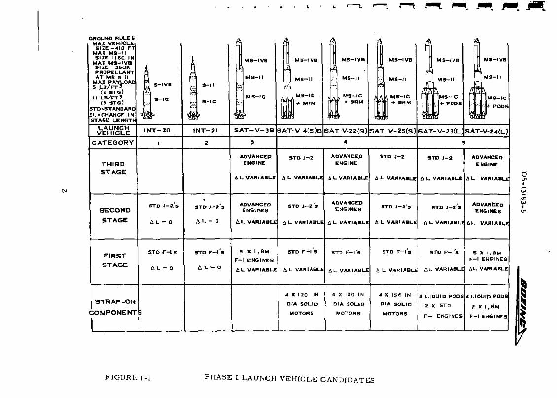
GROUND RULES MAX VEHICLE
S I Z E - 4 1 0 FT MAX M S - H SIZE 1160 IN
MAX M S - I V B SIZE 3SOK PROPELLANT AT MR 5 :i
MAX PAYLOAC 5 LB/FT-3
(2 STG) I I L B / F T 3
(3 STG) STD:STANDARD flL=CHANGE IN STAGE LENGTH
LAUNCH VEHICUE
A
tf S - l l
9-1C
•m I N T - 2 0 INT-21
w
M S - I V B
M S - I I
M S - I C
A
^
M 5 - I V B
M S - H
M S - I C
+ SRM
A M S - I V B
M S - I I
M S - I C + SRM
S A T - V - 3 B SAT-V-4(S)B
M S
M S
MS
+
SAT-V-22(S) S A T - V -
CATEGORY
THIRD
STAGE
ADVANCED ENGINE
0, L VARIABLE
STD J-2
A L VARIABLE
ADVANCED ENGINE
A L VARIABLE
STD J-
A L VAR
SECOND
STAGE
STD J - 2 S
i L - D
STD J - 2 3
i j L - 0
ADVANCED ENGINES
A L VARIABLE
STO J - 2 S
flL VARIABLE
ADVANCED ENGINES
A L VARIABLE
STD J
A L VAR
FIRST
STAGE
STD F - l s
A L - 0
STRAP-ON
COMPONENTS
STD F - l S
A L - O
5 X I . 6 M
F - t ENGINES
A L VARIABLE
STD F - l 5 STD F - l ' a
A L VARIABLE A L VARIABLE
STD F
6 L VAR
A X 120 IN
DIA SOLID
MOTORS
4 X 120 IN
DIA SOLID
MOTOR S
4 X 15
DIA S
MOTO
F I G U R E [-1 P H A S E I LAUNCH V E H I C L E CANDIDATES
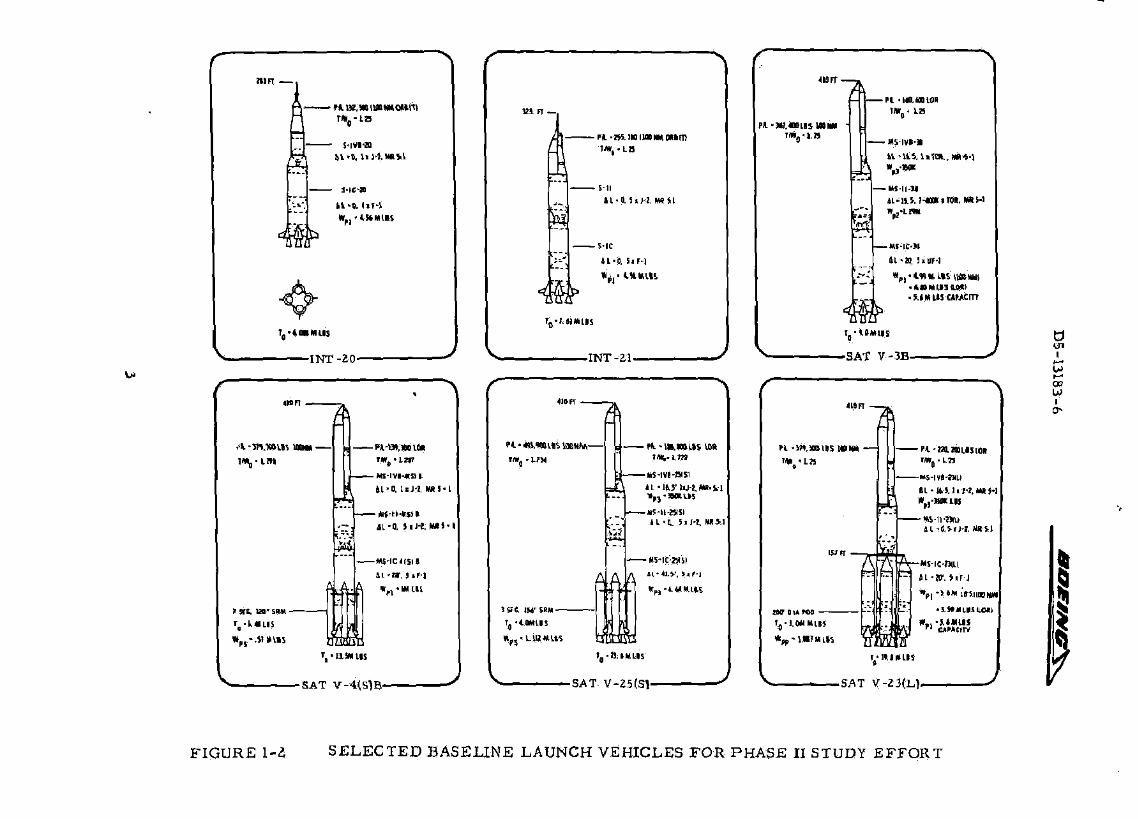
IW
IMFT
nt lKWI I f fMIOt t ro
r* 0 - ta
S-IM-M
Jl-IJ. UJ-l . MRftl
i-ica H - H i r - l
- INT-20-
mn •
/ft Sk-mjUM UMM
&
-Ct-W,WlW !*»„•L2P
-Mi-IVI-«fl>.
t l - d liJ'l, HRJ-L
- Mj-tMr$> I iL-0. J i J - * , l « i - l
- * i - IC* tS l i
1L-W, J.F-1
*, • a IM us
•SAT V-4(S)B- J
K i n —
-Pi-lH.lUIUONMOUm
S-ll
-SIC
tL'ft 5lF-]
* p l - IHHIRS
rD-I.NMLIS
INT -21 .
«ftfT
Pt-«.WILBSWflNAA P i -U» ,m i l s 10ft
*L ' l *J ' IU- i ,W. fc l
• JM-H-JSKI IL-D.. Si J-l MIS.]
•ws-ic-wsi
-SAT-V-25(S)- J
p* -w .«PL i i
Pt-SM.JO
W CIA KM
* f p- l .»7
FIGURE l-^ SELECTED BASELINE LAUNCH VEHICLES FOR PHASE II S
D5-13183-6 ^WBOKgy,
The launch vehicles in Categories 1 and 2 are Saturn V stage combinations for missions in the payload range between the current Saturn IB and Saturn V payload capability. The launch vehicles in Categories 3, 4, and 5 are advanced Saturn V configurations with payload capabilities beyond that of the existing Saturn V.
The five categories of vehicles are as follows:
Category 1 (MLV-SAT-INT-20) during Phase I was a family of two-stage launch vehicle candidates with standard size S-IC and S-IVB stages using standard F-l engines (three, four, and five) and a standard J-2 engine. A single baseline launch vehicle (Figure 1-2) was selected for the Phase II study effort.
Category 2 (MLV-SAT-INT-21) during Phase I was a family of two-stage launch vehicle candidates with standard size S-IC and S-II stages using standard F-l engines (three, four, and five) and J-2 engines (three, four, and five). A single baseline launch vehicle (Figure 1-2) was selected for the Phase n study effort.
Category 3 (MLV-SAT-V-3B) during Phase I was a family of two- and three-stage launch vehicle candidates with modified Saturn V stages using various types, numbers, and thrust levels of advanced engines in the upper stages and uprated F-l engines in the modified S-IC stage. A single baseline launch vehicle (Figure 1-2) was selected for the Phase II study effort.
Category 4 included modified Saturn V launch vehicles with strap-on solid motor boost-assist components. Three families of vehicles were studies as follows:
a. M-LV-SAT-V-4{S)B during Phase I was a family of two- and three-stage launch vehicles with modified Saturn V stages, standard F-l and J-2 engines with strap-on 120-inch diameter (five, six, and seven segmented) solid motors. A single baseline launch vehicle (Figure 1-2) was selected for the Phase II study effort.
b. MLV-SAT-V-22(S) during Phase I was a family of two- and three-stage launch vehicles with modified Saturn V stages using various types, numbers, and thrust levels of advanced engines in the upper stages, a modified S-IC stage with standard F-l engines in the first-stage, and strap-on 120-inch diameter (five, six, and seven segmented) solid motors. No launch vehicle in this family was studied beyond Phase I.
4

D5-13183-6 &CFMW4 3^
c. MI/V~-SAT-V-25{S) during Phase I was a family of two- and th ree - s t age launch vehicles with modified Saturn V s tages , standard F - l and J -2 engines, and s t rap-on 156-inch d iameter (two, three , and four segmented) solid motors . A single basel ine launch vehicle (Figure 1-2) was selected for the Phase II study effort.
Category 5 included modified Saturn V launch vehicles with strap-on boos t -as s i s t liquid propellant pods. Two families of vehicles were studied a s follows:
a. MLV-SAT-V-23(J_) during Phase I was a family of two- and th ree - s t age launch vehicles with modified Saturn V stages, standard F - l and J -2 engines, and four s t rap-on liquid propellant pods, each using two standard F - l engines. A single basel ine launch vehicle {Figure 1-2) was selected for the Phase II study effort..
b. MLV-SAT-V-24(L,) during P h a s e I was a family of two- and th ree - s t age launch vehicles with modified Saturn V stages using various types , n u m b e r s , and thrust levels of advanced engines in the upper s tages, a modified S-IC stage with uprated F - l engines, and four liquid propellant pods each containing two uprated F - l engines. No launch vehicles in this family were studied beyond Phase I.
5
D5-13183-6 • « O M 5 » V 4 g V v
2 .0 STUDY RESULTS
The six base l ine vehicles studied under the contract a r e logical configurations and candidates for payloads ranging from 78,000 pounds to 579,000 pounds to a 100 N. M. Ear th orbi t .
All eight configurations of the intermediate launch vehicles studied during the t r ade study phase a r e feasible using existing Saturn V stages with minimum modification. These vehicles have payload capabili t ies ranging from 73,000 pounds to 255,000 pounds and provide a family of flexible and cos t effective launch vehicles which a re available within the normal lead t ime required for the stage elements (2 years} .
The four uprated baseline vehicles a r e feasible configurations and logical candidates for payloads in excess of the cur ren t Saturn V capability. No major problem a rea s for development, production, or flight environmental cha rac te r i s t i c s were identified. The increased payload capability and improved Cost effectiveness over that of the existing Saturn V could be used to reduce overa l l miss ion cos t s . F o r some miss ions , increased payload capability can be used to simplify the mission mode and thus resul t in l e s s complex payload designs and fewer components. F o r example, a d i rect lunar shot for Apollo-type miss ions could great ly reduce the costs of the payload package from those cos t s required for the cur ren t LOR hardware by the elimination of the lunar rendezvous.
Explanation of the technical and r e sou rce data on this contract is summarized and reported in detail in the following documentation:
D5-13183 Summary Document D5-13183-1 Vehicle Description MLV-SAT-INT-20, -21 D5-13183-2 Vehicle Description MLV-SAT-V-3B D5-13183-3 Vehicle Description MLV-SAT-V-25(S) D5-13183-4 Vehicle Description MLV-SAT-V-4(S)B D5-13183-5 Vehicle Description MLV-SAT-V-23(L) D5-13183-6 Research & Technology Implications Report D5-13183-7 F i r s t Stage Cost Flan
6

D5-13183-6
3. 0 AERONAUTICS TECHNOLOGICAL IMPLICATIONS
3.1 AERODYNAMIC STATIC STABILITY
3,1.1 P rob lem Definition
The uprated Saturn V launch vehicles a r e aerodynamically unstable during boost flight. The amount of aerodynamic instabili ty is one of the major factors that determines the thrust vector control r e q u i r e ment. The uprated launch vehicles that use boost a s s i s t components a r e difficult to analyze because of the complex flow fields about the core vehicle and the s t rap-on solid motors or liquid propellant pods. Es t imates of the total normal force contribution to the core vehicle a r e difficult to make because of the ca r ryover from the s t rap-on to the core vehicle and the car ryover from the core vehicle to the s t rap-on s. The effect of the gap between the core vehicle and the s t rap-on and the effect of the s t rap-on on fin or engine shroud effect iveness a r e also difficult to determine. The lack of experimental data and the inability of the various theoret ical methods to analyze these complex vehicles add to the difficulties.
3.1. Z Solution Approach
It i s recommended that wind tunnel t e s t s be conducted on a Saturn V uprated configuration that uses solid s t rap-on motors for boost a s s i s t to de termine the effect of the s t rap-on motors on the vehicle aerodynamic coefficients. The tes t s should determine the increment in the aerodynamic coefficients so that the resul t s can be applied to other vehicles with a minimum of effort,
Typical wind tunnel data would have a variety of uses if i t followed the form shown on Figure 3-1.
3. 2 WIND SPEED ENVELOPE FOR LAUNCH TOWER CLEARANCE STUDIES
3.2.1 Prob lem Definition
In the definition of launch tower c learance , the 99 percent i le ground wind speed envelope i s used. This wind speed envelope is the resul t of a s tat is t ical analysis of ground windB measured over a number of yea r s in a clear field at Pa t r ick Air Fo rce Base at various altitudes and corre la ted with the power law U = Ui (Z/Z^J A wind speed envelope determine in this manner could be different from what a Saturn V type launch vehicle experiences because of large protuberances around the launch vehicle. The schematic in Figure 3-2 i l lus t ra tes the problem.
7
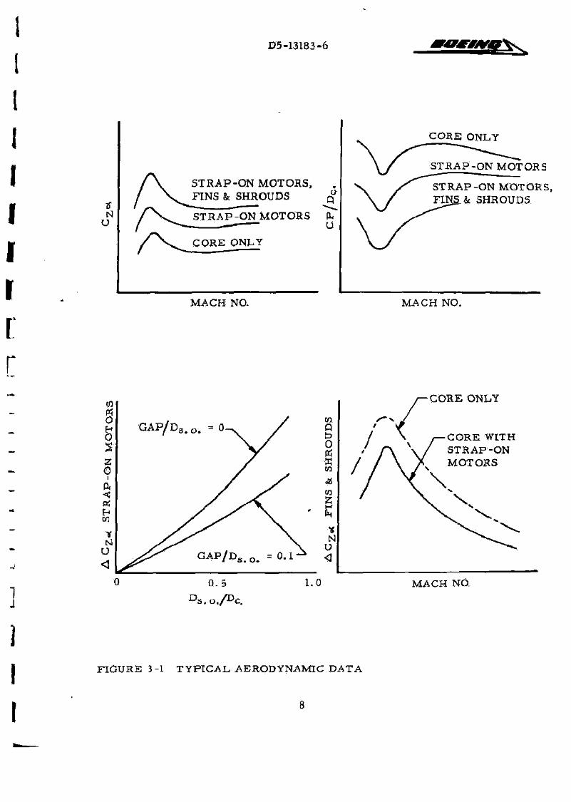
D5-13183-6 Fjm
N O
S T R A P - O N MOTORS, FINS & SHROUDS
/V, S T R A P - O N MOTORS
CORE ONLY
u
U
CORE ONLY
S T R A P - O N MOTOR S
R A P - O N MOTORS, & SHROUDS
MACH NO. MACH NO.
(0 M O H 0
0 i
P. <
en
U
G A P / D S . 0 . =0
CORE ONLY
C O R E WITH S T R A P - O N MOTORS
MACH NO.
FIGURE 3-1 T Y P I C A L AERODYNAMIC DATA
8
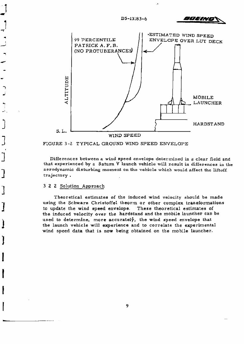
D5-13183-6
a i - j
H
s. L.
99 PERCENTILE PATRICK A . F . B. (NO PROTUBERANCES)
\ h
-ESTIMATED WIND SPEED ENVELOPE OVER LUT DECK
MOBILE LAUNCHER
HARDSTAND
WIND SPEED
FIGURE 3-2 TYPICAL GROUND WIND SPEED ENVELOPE
Differences between a wind speed envelope determined in a clear field and that experienced by a Saturn V launch vehicle will r esu l t in differences in the aerodynamic disturbing moment on the vehicle which would affect the liftoff t ra jectory .
3 2 2 Solution Approach
Theoret ica l es t imates of the induced wind velocity should be made using the Schwarz Chrigtoffei theorm or other complex transformations to update the wind speed envelope. These theoret ical es t imates of the induced velocity over the hardstand and the mobile launcher can be used to de termine , more accurate ly , the wind speed envelope that the launch vehicle will experience and to cor re la te the experimental wind speed data that is now being obtained on the mobile launcher.
9
4.0 ELECTRONICS AND CONTROL, TECHNOLOGICAL. IMPLICATIONS
4.1 LAUNCH TOWER CLEARANCE
4. 1.1 P r o b l e m Definition
Large launch vehicles of the nature of those considered in this study experience high horizontal t ranslat ions during lift-off when subjected to design winds and biased with off nominal design and construction p a r a m e t e r s . Large drift distances and the result ing probability of tower collision can require extensive modification to existing launch pad facil i t ies,
4. 1. 2 Solution Approach
Investigate the effect of distr ibuted aerodynamics on vehicle lift-off t ra jectory and extend the study of lift-off dynamics to include rep resen ta tion of res t ra ined re lease and malfunction conditions (engine loss) . P a r a meter ize rigid body control sys tem feedback loops to minimize drift d i s tance while remaining within attitude (guidance) cons t ra in ts , A six degree of freedom digital simulation should be used tb conduct these studies.
4. 2 E F F E C T OF CONTROL MODES ON VEHICLE LOADS
4 .2 .1 P rob lem Definition
The effect of a l te rnate control modes on gimbal requi rements was examined during the course of these studies. These resul t s showed that the effect of varying control modes on gimbal displacement was negligible, and that one control system could not be recommended over another on the basis of r e duced TVC requ i remen t s . This resul t does not prec lude , however, the possible advantage of one control system over another in the a rea of reducing bending loads. Limited studies showed differences in maximum bending responses of 12 pe rcen t and 5 percent r-espectively for the MLV-Saturn V-3B and the MLV-Saturn V-4(S)B vehicles when comparing an attitude-attitude ra te control sys tem to attitude -at t i tude ra te with angle of at tack feedback. These resul ts were obtained without optimizing control gains for load relief and using synthetic wind representa t ions .
The amount of load reduction available by control sys tems optimisation is a function of control mode, vehicle configuration, and the nature of the wind forcing input. These effects should be a s se s sed to provide information upon which selections of optimum control sys tems for the uprated Saturn family of vehicles may be based.
10

D5-13183-6 ^
4. 2. Z Solution Approach
A comprehensive study is indicated uaing candidate control sys tems with gains optimized for load relief. In order to determine the relat ive effect of varying vehicle configuration, it is suggested that the family of uprated and intermediate Saturn V vehicles in its entirety be examined. Selected vehicles among these should be examined using both synthetic and rea l wind r ep resen ta tions which are consistent with each other. A number of measured (J imsphere) profiles of varying severi ty would be selected and consistent synthetic profi les having the same peak wind magnitude at the s ame altitude would be constructed. Wind shear of the synthetic profiles would be adjusted to give the s ame peak bending response using nominal atti tude-atti tude r a t e control before control systems optimizations for load relief a r e begun. Stability analyses using the elastic proper t ies of the vehicles and varying sensor placement to a s s u r e practicabil i ty of the control gains selections and optimizations would be requi red ,
The feasibility of employing multiple sensors and weighted control sys tems feedbacks to limit vehicle elast ic bending response should be examined,
4. 3 RANGE/VEHICLE COMMUNICATION INTERFERENCE
4 .3 .1 - RF Interference F r o m Added Strap-On Structure
4. 3.1.1 P rob l em Definition
The addition of s t rap-on boosters , ei ther liquid or solid, may place the s t ructure of the booster in a position that in terferes with antenna look angles from the vehicle to the ground station. Each antenna on the Saturn V stages should be considered to determine if s t ruc ture obscures line of sight to any ground station.
The s t ruc ture of the s t rap-on booster also may modify the antenna radiation pa t te rns . The booster s t ructure acts as ref lectors which will modify the radiat ion charac ter i s t ics of each antenna.
4, 3 .1. 2 Solution Approach
Antenna radiat ion pat tern tes ts should be conducted on an antenna range using models of the vehicles with s t rap-on boos ters . These tes t s should be per formed for all of the antenna sys tems on every stage. A complete descript ion of an antenna's radiation field as it exists in space about the vehicle should be plotted. The tes t s and plotting of data should be conducted to the same groundrules as the data presented in Boeing Document D5-155a6-l, May 16, 1966, t i t le : "Saturn V Antenna Systems AS-501, " conducted for contract NAS8-5608.
11
D5-13183-6
4 . 3 . 1 . 2 Solu t ion A p p r o a c h (Cont inued)
It m a y be n e c e s s a r y to r e l o c a t e the an t ennas by moving t h e m ou tward f o r w a r d , o r to a d i f fe ren t a n g u l a r pos i t i on to i m p r o v e the r a d i a t i o n p a t t e r n a n d / o r look ang le . It m a y a l s o be n e c e s s a r y to change the des ign of the an tenna s y s t e m s to i m p r o v e the r a d i a t i o n p a t t e r n .
4. 3 . 2 R F I n t e r f e r e n c e F r o m Modif ied Exhaus t F l u m e
4. 3 . 2 .1 P r o b l e m Defini t ion
The u p r a t e d v e h i c l e s have e n l a r g e d exhaus t p l u m e s due to i n c r e a s e d m a s s flow. The so l id s t f a p - o n m o t o r s a l s o add di f ferent exhaus t p r o duc t s , inc lud ing m e t a l p a r t i c l e s , which i n c r e a s e the d e g r a d a t i o n of the R F s y s t e m .
4. 3 . 2. 2 Solut ion A p p r o a c h
The c o m m u n i c a t i o n data r e c o r d e d f r o m Ti tan III f l ights should be e v a l u a t e d to d e t e r m i n e R F i n t e r f e r e n c e th rough the e x h a u s t p l u m e of combined l iqu id eng ines and s o l i d r o c k e t m o t o r s . Th is da ta should be c o r r e l a t e d to da ta f r o m S a t u r n I f l ights and o the r s o u r c e s of R F i n t e r f e r e n c e da t a t h r o u g h e x h a u s t p l u m e s . This eva lua t ion shou ld c o n s i d e r t he R F i n t e r f e r e n c e a s a funct ion of an tenna look angle , ' us ing the look ang le c u r v e s in Sec t ion 5. 2 . 7 of d o c u m e n t s D5-13183-3, - 4 , and - 5 .
4. 3 , 3 Modif ied Antenna S y s t e m
4 . 3 . 3 . 1 P r o b l e m Definit ion
The i m p r o v e m e n t s tudy ind i ca t ed a r e q u i r e m e n t to p lace a redundant s e t of M 3 - I C a n t e n n a s on the s t r a p - o n b o o s t e r s which would be u s e d p r i o r to s t ag ing of t he s t r a p - o n b o o s t e r s . The s t r a p - o n b o o s t e r s have R F s y s t e m s independen t of the S a t u r n V, but r e q u i r e combina t ion of the four b o o s t e r R F c i r c u i t s on the MS-IC and r e d i s t r i b u t i o n to an t ennas on t he s t r a p - o n s . The l o n g e r c i r c u i t p a t h s and added swi tch ing f r o m the t r a n s m i t t e r s to the a n t e n n a s m a y p r o d u c e i n c r e a s e d R F d e g r a d a t i o n a s wel l as p r e s e n t i n g h a r d w a r e p r o b l e m s for the p r o p o s e d s y s t e m .
4. 3. 3 . 2 Solution A p p r o a c h
The mod i f i ed an t enna s y s t e m s p r o p o s e d (in Sec t ions 6. 1. 4 of documen t s D5-13183-3, - 4 , and -5) for u s e wi th the s t r a p - o n b o o s t e r s should be e v a l u a t e d ana ly t i ca l l y , and then t e s t e d with a s y s t e m s b r e a d b o a r d us ing S- IC c o m p o n e n t s .
12
D5-13183-6 ^ M K g g i
4. 3. 3. 2 Solution Approach (Continued)
The resu l t s of this investigation would be to determine a reas of RF systems adequacy, recommend changes to the Saturn V sys tems , and define further testing required. It is necessa ry to investigate the RF systems for the upper stages as well as the MS-IC to a s su re adequare communication io r the vehicle.
13
D5-13183-6
5. 0 MATERIALS AND STRUCTURES TECHNOLOGICAL IMPLICATIONS
5.1 STABILITY CRITICAL STIFFENED CYLINDRICAL SHELL DESIGN
5.1.1 Prob lem Definition
Since the original design of the Saturn V vehicle, severa l methods of analyses have been developed to more accurately predict the load-carrying capability of s tabi l i ty-cr i t ica l axially compressed stiffened cylinders . However, none of these methods have been proved re l iable for a l l stiffened cylinder configurations applicable to the Saturn V vehicle. One of these methods, developed by Boeing, {Ref. D5-13272) considers all three possible modes of instability failures and has been part ia l ly verified with resul ts from the S-IC corrugated intertank test p r o g r a m and from various t e s t data in the l i t e ra tu re . This method is current ly being extended to account for the inc rease in load-carrying capability due to p r e s s u r e stabilization.
5.1. 2 Solution Approach
1. Verify by test and analyses the validity and range of application of the available analytical procedures including the method developed by Boeing.
2. Compare resul t s of the various methods.
3. Use the b e s t of these methods for each type of s t i0ehed cylinder applicable to the Saturn V vehicle and re -eva lua te the various uprated Saturn V vehicles for possible weight savings and increased r e liability.
5. 2 PAYLOAD ENVELOPE WIND SENSITIVITY
5, 2.1 Problem Definition
The intermediate vehicles INT-20 and INT-21 were studied using the Apollo payload shape and were shown to have adequate strength without modification using cu r ren t Saturn wind c r i t e r i a . Due to the limited volume of the Apollo envelope, and la rger payload weights afforded by these vehicles for orbital miss ions , payload densit ies are relatively high. Actually these vehicles have considerably more versat i l i ty for car ry ing pay loads of higher volume and lower density during extensive periods of the year. This v e r s a tility is available from two sources : (1) using reduced factors of safety for un-manned miss ions , and (2) from reduced wind magnitudes which exist during periods of the year for which launches may be planned.
14
D5-13183-6
5 .2 ,2 Solution Approach
In order to define the versati l i ty which exists in this respec t , it is suggested that comprehensive analyses be performed using a family of pay-load shapes and s izes and winds of varying magnitude as defined by MSFC cr i t e r i a for each month of the year . Payload length l imits would be es tablished for each month of the year as a function of peak wind speed for manned and un-manned factors of safety within the s t ruc tura l Capability of these vehicles. F rom these data est imates of launch availability versus month of the year may be obtained for payloads of varying size on a probabil ist ic bas is . Such, information i s very desirable for planning purposes .
5. 3 FLIGHT LOADS PROBABILITY
5.3.1 Prob lem Definition
Generally speaking synthetic wind representa t ions which have been developed from s ta t i s t ica l analysis of measured wind data do not produce loads responses with the same probability, i. e. , there is no di rect c o r r e l ation between the probabilit ies of peak wind speed, wind shear , altitude, and direction, and load exceedance probability. Current ly there a re in sufficient data upon which to base computation of the combined probability of ail wind p a r a m e t e r s so that even synthetic c r i te r ia must s t i l l be selected through exerc i se of sound engineering judgments. Obviously conservat ism is a desirable considerat ion in this case. There a re sufficient measured winds, however, to approach the problem from the di rect load exceedance standpoint. Improved wind measurement systems a re producing higher resolution profi les . It should be possible to use these data coupled with other measured wind information to compute load exceedance probability from s ta t i s t ica l samples of measured profi les . This approach would reduce the need for conserva t i sm associated with engineering judgments which have been required in the past in the development of synthetic profi les.
5. 3. 2 Solution Approach
Up to this t ime such solutions have not been pract icable due to the limited wind information available, extensive computer t imes required to obtain solutions for adequate s tat is t ical samples of measured profiles, limited accuracy of the profiles themselves , and absence of corre la t ions between mean wind and random turbulence responses . As a result, no methods have been tai lored to this purpose which encompass the complete solution.
In order to obtain loads of known exceedance probability the following is required:
15

D5-13183-6 ^ g E g X / V g - V .
5 .3 .2 Solution Approach (Continued)
1. Development of high speed digital or analog simulations to obtain probability dis tr ibut ions of loads responses to s ta t i s t ica l samples of mean winds.
2. Utilization of J imsphe re data to obtain power spectra l densities of random turbulence and associa ted mean wind prof i les .
3. Stat is t ical order ing of vehicle responses to mean winds and random turbulence and cor re la t ion of these responses using vehicle responses to to ta l wind profi les ( J imsphere) .
The resul t would be bending load probability distributions for desired launch periods as functions of launch azimuth for c r i t i ca l vehicle stations for all t imes during boost . Such information would be very valuable to a s s i s t in the select ion of design c r i t e r i a for the advanced Saturn family of vehicles . In addition, corre la t ions of these resul t s could be made with synthetic profi les developed through stat is t ical analysis of the winds themse lves . This would provide consistent synthetic c r i t e r i a for use in design studies and the relat ionships between p r imary wind s tat is t ical pa ramete r s and the s ta t is t ical p roper t i es of vehicle r e sponses .
5. 4 GROUND WIND LOADS
5. 4.1 P r o b l e m Definition
Computation of the ground winds loads response for l a rge launch vehicles is one of the mos t problematic a r ea s faced in the course of vehicle design. Limited knowledge of wind forcing functions and the coupled elastic response to random vor tex shedding has historically required wind tunnel verification or total re l iance on wind tunnel r e s u l t s . Vehicle s ize has p rogressed to the point where l imited knowledge of scaling relationships seriously hinders application of wind tunnel r e su l t s . Considerable t ime and effort is being spent on the cu r ren t Saturn V p rogram to lea rn more about this problem area including full s ca le ground winds test ing using the AS-500F vehicle. An effort should be made to assemble all available knowledge from this and other sources and to extrapolate the resul ts to the l a rger uprated configurations. In addition, wind tunnel tes t s of uprated Saturn configurations will be required.
5 .4 .2 Solution Approach
Apply these resu l t s to the la rger uprated Saturn configurations and obtain revised ground wind loadings for design purposes .
16
D5-13183-6
5. 4 . 2 Solution Approach (Continued)
1„ P lan and conduct wind tunnel tes t s to establish ground wind load responses of uprated configurations.
2. Utilize this information and cur ren t Saturn V analysis and tes t resul t s to extend analyses methods to include the l a rger uprated vehicles.
3. Revise ground wind loads for design purposes based on these r e su l t s .
17
P5-13183-6
6. 0 LOW COST LIQUID PROPELLANT POD
Large p r e s s u r e fed liquid engine systems for boos t -ass i s t and for booster application a re feasible , and approach the simple sys tems and s t ructures of solid rocket m o t o r s .
6. 1 PROBLEM DEFINITION
The use of liquid propellant pods for boos t -ass is t on the MLV-SAT V-23(L) configuration provided a flexible method for vehicle uprating. However, the pod design was based on S-IC technology and concepts which result in higher costs than for solid mo to r s .
The use of a p r e s s u r e fed engine(s) and monocoque propellant tank s t ruc ture can make the pods competitive with solid motors on a cost bas i s . The liquid propellants a r e cheaper than solid propel lants , and transportat ion and handling of the dry stage is ea s i e r . The specific impulse of the liquid pod is better than the solid motors which provides a performance advantage.
6. 2 SOLUTION APPROACH
I I
; The feasibility of a simplified liquid pod design which will be cos t -
competitive with solid motors should be determined. The design should be optimized from a cost and rel iabil i ty standpoint, with l e s s e r emphasis on performance.
J Evaluation of pod components and sys tems to define performance
charac te r i s t i cs and cost would lend not only to understanding the specific reasons for cost differences, but a lso to identify means of optimizing cost effectiveness. The potential of incorporating the following into the pod d e sign should rece ive attention:
a. Simplified engine - el iminate turbopump (pressure-fed) - minimum valves and controls .
b. Simplified pressur iza t ion system - minimum complexity and components, and simple controls .
c. Simplified propellant tankage (monocoque structure) and thrust s t ruc tu re , made of inexpensive ma te r i a l s and fabrication techniques, requir ing minimum inspection and testing.
d. Storable propellants and pressur iza t ion gases , packaged, and sealed.
These analyses of a low-cost pod should be compared in size and cost-effectiveness to the cryogenic pump-fed pod and solid motors used in the studies under NAS8-20266.
18