Embed Size (px)
Citation preview

1
Final Project Report
Development of carbon and sulphur tolerant anodes of solid oxide fuel cells
Project Agreement No. AOARD-074089 & AOARD-084117
Project Period: 03 August 2007 – 02 August 2009
Dr San Ping Jiang
(Principal Investigator)
School of Mechanical and Aerospace Engineering
Nanyang Technological University
Singapore 639798
Date: 14 January 2010
Report Documentation Page Form ApprovedOMB No. 0704-0188
Public reporting burden for the collection of information is estimated to average 1 hour per response, including the time for reviewing instructions, searching existing data sources, gathering andmaintaining the data needed, and completing and reviewing the collection of information. Send comments regarding this burden estimate or any other aspect of this collection of information,including suggestions for reducing this burden, to Washington Headquarters Services, Directorate for Information Operations and Reports, 1215 Jefferson Davis Highway, Suite 1204, ArlingtonVA 22202-4302. Respondents should be aware that notwithstanding any other provision of law, no person shall be subject to a penalty for failing to comply with a collection of information if itdoes not display a currently valid OMB control number.
1. REPORT DATE 26 JAN 2010
2. REPORT TYPE FInal
3. DATES COVERED 03-08-2007 to 02-08-2009
4. TITLE AND SUBTITLE Development of carbon and sulfur tolerant anodes of solid oxide fuel cells
5a. CONTRACT NUMBER FA23860814117
5b. GRANT NUMBER
5c. PROGRAM ELEMENT NUMBER
6. AUTHOR(S) San Ping Jiang
5d. PROJECT NUMBER
5e. TASK NUMBER
5f. WORK UNIT NUMBER
7. PERFORMING ORGANIZATION NAME(S) AND ADDRESS(ES) Nanyang Technological University,50 Nanyang Ave,Singapore 639798,Singapore,SP,639798
8. PERFORMING ORGANIZATIONREPORT NUMBER N/A
9. SPONSORING/MONITORING AGENCY NAME(S) AND ADDRESS(ES) AOARD, UNIT 45002, APO, AP, 96337-5002
10. SPONSOR/MONITOR’S ACRONYM(S) AOARD
11. SPONSOR/MONITOR’S REPORT NUMBER(S) AOARD-084117
12. DISTRIBUTION/AVAILABILITY STATEMENT Approved for public release; distribution unlimited
13. SUPPLEMENTARY NOTES Project AOARD-074089 was the preceding grant to this report
14. ABSTRACT GDC-impregnated Ni/GDC anodes show the significant enhancement of the sulfur-tolerance of the anodes.However, the microstructure of GDC-impregnated Ni/GDC anodes still changes significantly in H2S-H2,indicating that GDC nanoparticles may not be able to completely inhibit the poisoning effect of sulfur onNi/GDC anodes under present conditions studied. Co-impregnation of Pd-CeO2 was found to be mosteffective to enhance the activity of the Ni/GDC anodes for the hydrogen oxidation reaction in H2S-H2 andthe polarization performance is stable under the condition of 100 ppm H2S-H2 and 200 mAcm-2 at 800ocfor 50 hrs. Most important, the SEM results indicate that the impregnated Pd-CeO2 nanoparticles areeffective to retard the poisoning effect of sulfur on the microstructure of Ni/GDC anodes, as compared theinhibiting effect of impregnation of Pd or GDC nanoparticles separately.
15. SUBJECT TERMS fuel cells electrode, solid oxide fuel cells, Ceramics, ion impregnation
16. SECURITY CLASSIFICATION OF: 17. LIMITATION OF ABSTRACT Same as
Report (SAR)
18. NUMBEROF PAGES
48
19a. NAME OFRESPONSIBLE PERSON
a. REPORT unclassified
b. ABSTRACT unclassified
c. THIS PAGE unclassified
2
ABSTRACT
The objective of the project is to develop carbon and sulfur tolerant anodes of solid oxide fuel cells (SOFCs). Due to the complicity nature of the project, the scopes of the projects were divided into two main parts: the investigation and development of carbon tolerant anodes and the investigation and development of sulfur tolerant anodes. In the first part, Pd-impregnated La0.75Sr0.25Cr0.5Mn0.5O3-δ/yttria-stabilized zirconia (LSCM/YSZ) composite anode is investigated in detail for the direct utilization of ethanol and methane (the main component of natural gas) in SOFCs. Impregnation of Pd nanoparticles significantly promotes the electrocatalytic activity of LSCM/YSZ composite anodes for the ethanol and methane electrooxidation reaction. At 800°C, the electrode polarization resistance for the methane oxidation is reduced by a factor of 3 after impregnation of 0.10 - 0.66 mg cm-2 Pd. No carbon deposition was observed for the reaction in ethanol and CH4 on Pd-impregnated LSCM/YSZ composite anodes. The results demonstrate that the Pd-impregnated LSCM/YSZ composite is a promising carbon-tolerant anode for natural gas fuel-based SOFCs. The electrochemical impedance behavior for the oxidation reaction in hydrogen, methane and ethanol over a pure and Pd-impregnated Ni/GDC anode of SOFC were also studied under open circuit and dc bias conditions. The preliminary results show that the electrocatalytic activity of Ni/GDC cermet anodes for the oxidation reactions of hydrogen, methane and ethanol can be significantly increased by the addition of Pd nanoparticles and by applying dc bias. This indicates the promising potential of development of carbon tolerance Ni/GDC anodes by optimization of the impregnation of catalytic particles and operational conditions. In the second part, selected vanadate, chromite and titanate perovskite oxides were successfully synthesized by solid state reaction method and their stability in air, 10%H2-N2 and 1%H2S-H2 at 1000 and 1200oC was evaluated by XRD analysis. The results indicate that pure La0.75Sr0.25Cr0.5Mn0.5O3-δ (LSCM) is not stable in sulfur-containing fuel. However, the stability of LSCM in 1%H2S-H2 can be improved significantly by doping of vanadium or titanium at the B-site of LSCM. Due to the high electrical conductivity, Ni-based cermet anodes such as Ni/GDC and Ni/YSZ were investigated in H2S-H2 fuel. The results indicate that the sulfur tolerance of Ni/GDC anode is significantly better than that of Ni/YSZ anodes. Thus the work was concentrated on the understanding and improvement of the sulfur tolerance of Ni/GDC anodes. Impregnation of Pd nanoparticles reduces significantly the electrode polarization resistance and enhances the stability of the polarization performance of the Ni/GDC anodes in H2S-H2 fuel. The results indicate that the infiltrated Pd nanoparticles inhibit the reaction between sulfur and nickel, significantly reducing the poisoning effect of H2S on the modification of Ni/GDC anode. GDC-impregnated Ni/GDC andoes also shows enhanced sulfur tolerance. However, the microstructure of GDC-impregnated Ni/GDC anodes changes in H2S-
3
H2, indicating that GDC nanoparticles cannot completely inhibit the poisoning effect of sulfur on Ni/GDC anodes. Finally, co-impregnation of Pd-CeO2 was found to be most effective to enhance the activity of the Ni/GDC anodes for the hydrogen oxidation reaction in H2S-H2 and Pd- CeO2 impregnated Ni/GDC anode shows the highest sulfur tolerance in H2S-H2. There is almost no degradation in polarization performance under the condition of 100 ppm H2S-H2 and 200 mAcm-2 at 800oC for 50 hrs. Most important, the SEM results indicate that the impregnated Pd-CeO2 nanoparticles are effective to retard the poisoning effect of sulfur on the microstructure of Ni/GDC anodes, as compared to the inhibiting effect of impregnated Pd or GDC nanoparticles separately. Though the tests were not performed on the carbon and sulfur tolerance of Pd-CeO2-impregnated Ni/GDC anodes, it is expected that Pd-CeO2 impregnated Ni/GDC would exhibit significant tolerance and activity towards sulfur-containing hydrocarbon fuels such as natural gas.
KEYWORDS
Solid oxide fuel cells; carbon tolerance; sulfur tolerance; Pd; CeO2; impregnation;
La0.75Sr0.25Cr0.5Mn0.5O3-δ/yttria-stabilized zirconia (LSCM/YSZ); Ni/GDC anodes.
4
TABLE OF CONTENTS
ABSTRACT ................................................................................................................................. 2
Chapter 1: Introduction ........................................................................................................... 5
Chapter 2: Nano‐structured Palladium‐La0.75Sr0.25Cr0.5Mn0.5O3‐δ/Y2O3‐ZrO2 Composites As Carbon‐Tolerant Anodes .......................................................................................................... 7
Chapter 3: Carbon tolerance of Pd‐impregnated Ni/GDC anodes of SOFCs .......................... 19
Chapter 4: Evaluation of perovskite oxides as potential sulfur tolerant anode materials for solid oxide fuel cells ............................................................................................................... 23
Chapter 5: Ni/GDC and Ni/YSZ cermet anodes in H2/H2S Fuels ............................................. 26
Chapter 6: Sulfur tolerance of Pd‐impregnated Ni/GDC anodes ........................................... 36
Chapter 7: Sulfur tolerance of GDC and Pd‐CeO2 impregnated Ni/GDC anodes ................... 41
List of Publications ................................................................................................................. 46
References: ............................................................................................................................ 47
5
Chapter 1: Introduction
Development of solid oxide fuel cells (SOFCs) that can run on liquid hydrocarbon fuels such as ethanol and diesel is important as compact power sources for portable and military transportation applications. Hydrogen is not an energy sources and has to be produced via electrolysis or reforming of other hydrocarbon fuels. On the other hand, liquid hydrocarbon fuels have much higher energy density than gaseous fuels like hydrogen and natural gas. The SOFCs based on liquid fuels like ethanol and diesel can make the power system much more compact and fuel friendly. Sulfur is a common contaminant in many hydrocarbon fuels. Ni is an excellent catalyst for H2 electro-oxidation reaction. However, hydrogen sulfide could chemisorption on the Ni surface at low H2S concentrations and react with Ni to form nickel sulfide (NiS), blocking the active reaction sites for the H2 adsorption, dissociation, oxidation, and diffusion along Ni surfaces [1]. So Ni/YSZ based cermet anodes have a very low tolerance to fuels containing H2S even at a very low level (ppm) [2]. Thus, the development of new anode materials or Ni-based anodes with enhanced stability in hydrocarbon fuels and high sulfur tolerance is critical for SOFCs. The objectives of the AFRL Project are to develop carbon- and sulfur-tolerant anodes for SOFCs. Due to the complicity nature of the project, the scopes of the projects were divided into two main parts: the investigation and development of carbon tolerant anodes and the investigation and development of sulfur tolerant anodes. In the first part of the project, La0.75Sr0.25Cr0.5Mn0.5O3-δ/yttria-stabilized zirconia (LSCM/YSZ) and Ni/GDC anodes were investigated in detail for the direct utilization of ethanol and methane (the main component of natural gas) in SOFCs. The effect of the impregnation of Pd nanoparticles on the activity and stability of the LSCM/YSZ and Ni/GDC in ethanol and methane was investigated in details. In addition, the phase stability of selected vanadate, chromite and titanate perovskite oxides was also studied in air, 10%H2-N2 and 1%H2S-H2 at 1000 and 1200oC. However, due to the inherently low conductivity of the chromite, vanadate and titanate perovskite oxides, work did not perform for the performance and activity of perovskite oxides in sulfur-containing fuels. The emphasis of the project was shifted to the Ni-based materials due to the high electrical conductivity and high activity for hydrogen and hydrocarbon fuels. A comparative investigation was carried out on Ni/GDC and Ni/YSZ to fundamentally understand the effect of the oxide phase in the cermet anodes. The effect of the impregnation of Pd nanoparticles in Ni/GDC cermet anodes was also investigated and the results indicate that the infiltrated Pd nanoparticles inhibit the reaction between sulfur and nickel and GDC particles, significantly reducing the structural modification of Ni/GDC anode by H2S. GDC-impregnated Ni/GDC andoes also

6
shows enhanced sulfur tolerance. However, the microstructure of GDC-impregnated Ni/GDC anodes changes significantly in H2S-H2, indicating that GDC nanoparticles may not completely inhibit the poisoning effect of sulfur on Ni/GDC anodes. Finally, the co-impregnation of Pd and CeO2 was investigated briefly on the sulfur tolerance and activity of Ni/GDC anodes in H2S-H2 fuels and the results show the promising potential in the development of highly tolerance anodes towards sulfur based on conventional Ni/GDC anodes.

7
Chapter 2: Nanostructured Palladium
La0.75Sr0.25Cr0.5Mn0.5O3δ/Y2O3ZrO2 Composites As
CarbonTolerant Anodes
Background In solid oxide fuel cells (SOFCs), Ni has excellent electrocatalytic activity for the H2 oxidation, high electrical conductivity and good chemical stability with YSZ electrolyte and it is available in abundance. Unfortunately, Ni-based anodes are not stable in hydrocarbons ascribed to carbon deposition[3, 4] and sulfur poisoning.[2] High stream/carbon ratio is needed to suppress the carbon deposition on Ni-based anodes, which is not an attractive option for fuel cell as it reduces the electric efficiency by diluting fuel and causes the thermal management problems. To overcome the limitations of Ni/YSZ based anodes, there are currently activities in the development of alternative anode materials such as ceria, titanate and lanthanum chromite based oxides [5, 6]. For example, Tao et al.[7] showed the comparable performance of La0.75Sr0.25Cr0.5Mn0.5O3-δ (LSCM) anodes in wet H2 with that of the Ni/YSZ based cermets. LSCM is chemically stable to YSZ with relatively good stability in a reducing atmosphere at high temperatures, and it is a p-type conductor with conductivity of ~ 38 S cm-1 in air and 1.5 S cm-1 in 5% H2 at 900 oC [8]. Therefore LSCM is considered as a promising anode material for SOFCs. However, the catalytic activity of LSCM for methane steam reforming is low [9]. Our studies on LSCM-based electrodes show that the electrocatalytic activity of LSCM-based materials is not high in methane fuel [10]. One strategy to improve the performance of SOFC electrodes is the catalytic promotion with the addition of nanosized oxides or metals into a SOFC electrode. We have shown previously that introduction of Gd-doped CeO2 (GDC) nanoparticles substantially enhances the activity of LSCM for methane oxidation [11]. In this project, we impregnated nanosized Pd particles into LSCM/YSZ composite anode to promote the electrocatalytic activity and carbon-tolerant of LSCM for the methane electrochemical oxidation reaction. The catalytic promotion of Pd in LSCM/YSZ anode was investigated with different Pd loadings in weakly humidified H2 and CH4 streams. The promotion mechanism of Pd for methane oxidation is discussed. Experimental YSZ electrolyte substrates were prepared from 8 mol% YSZ (Tosoh Corporation, Japan) powders by die pressing and sintered at 1550 oC for 4 h. The diameter of the YSZ electrolyte was ~20 mm. The surface of YSZ discs was ground using sandpaper to increase the roughness of the surface and the contact between the electrode and the
8
YSZ electrolyte. The thickness of the YSZ electrolyte was kept constant as 1.3±0.03 mm by grinding. La0.75Sr0.25Cr0.5Mn0.5O3-δ (LSCM) powder was prepared using glycine-nitrate process (GNP). Stoichiometric amounts of lanthanum nitrate (La(NO3)3·6H2O), strontium nitrate (Sr(NO3)2), chromium nitrate (Cr(NO3)3·9H2O) and manganese nitrate (Mn(NO3)2) (all from Sigma-Aldrich) were dissolved in distilled water. Then stoichiometric amount of glycine (NH2-CH2-COOH, Alfa-Aesar) was added to the solution, and was boiled to evaporate excess water. The resulting viscous liquid was ignited and underwent combustion to form black ash. Afterwards the ash was calcined at 1200 oC in air for 2 h to obtain LSCM powder. LSCM and YSZ powder in a 1:1 weight ratio were mixed and ball milled in isopropanol for 10 h. After drying, the mixture was mixed intimately with polyethylene glycol (400 MW) and 5 wt % graphite as a pore-former to form the slurry of LSCM/YSZ composite. Subsequently the slurry was painted to the YSZ electrolyte disk and sintered at 1200 oC in air for 2 h to produce LSCM/YSZ (50/50 wt %) composite anode. The thickness and the surface area of the anode after sintering were around 40 µm and 0.4 cm2, respectively. Impregnation of Pd was performed by dripping a drop of 0.25 M Pd(NO3)2 solution to the surface of a LSCM/YSZ composite anode, and the solution infiltrated through the porous anode by a capillary action. The electrode surface was wiped gently with a soft tissue and dried in air. The impregnated anode was fired at 700 oC in air for 1 h to decompose Pd(NO3)2 to PdO. The PdO loading in the anode was determined from the weight difference before and after impregnation, and the loading was increased by repeating the impregnation process. For the sake of simplicity, the impregnated Pd loading was converted and calculated based on metallic palladium, i.e., Pd loading. The phases of synthesized LSCM powder and LSCM/YSZ composite anodes with and without Pd impregnation were identified by powder X-ray diffraction (XRD) (Philips, PW 1050). A three-electrode arrangement was used for the electrochemical measurement. Platinum paste was painted onto the opposite side of the LSCM/YSZ composite anode as the counter electrode and to the edge of the YSZ substrate to form a ring reference electrode. Methane and hydrogen humidified at room temperature (97% CH4/3% H2O, 97% H2/3% H2O) were used as fuels. The fuel flow rate was controlled at 80 mL min-1 while the counter and reference electrodes were exposed to air. Electrochemical impedance spectroscopy (EIS) was carried out using a Solartron 1260 frequency response analyzer coupled with a Solartron 1287 electrochemical interface. The impedance spectra of the cell were recorded at open circuit potential (OCP) with amplitude of 10 mV over the frequency range from 0.01 Hz to 1 MHz. The electrode polarization (interface) resistance, RE was determined by the difference between the low and high frequency intercepts on the impedance curves. The electrode ohmic resistance, RΩ was measured from the high frequency intercept on the impedance curves. The polarization curves were measured by sweeping the
9
potential at a scan rate of 5 mV s-1. For comparison, LSCM/YSZ composite anodes without Pd impregnation were measured under the same conditions. Microstructure of the anodes before and after testing was inspected by scanning electron microscopy (SEM, JEOL JSM-6340F, Japan). X-ray photoelectron spectroscopy (XPS) was performed on the Pd-impregnated LSCM/YSZ samples before and after reduction using a Kratos AXIS Ultra spectrometer with a monochromatized Al Ka X-ray source (1486.71 eV). The sample was reduced in hydrogen atmosphere at 900oC and was cooled quickly in the hydrogen atmosphere to room temperature. The binding energy scale of the XPS spectrum was calibrated with the C 1s peak at 285.00 eV. Results and discussions Phase identification and microstructure of anodes
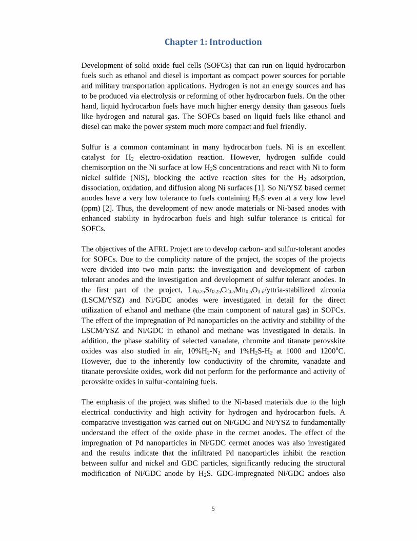
Figure 1. XRD patterns (a) LSCM powder, (b) LSCM (50 wt %)/YSZ (50 wt %) composite, and (c) impregnated Pd-LSCM/YSZ composite (Pd loading = 1.2 mg cm-2). The XRD results of LSCM powder and LSCM/YSZ composite powder with and without Pd impregnation are shown in Fig. 1. The patterns of synthesized LSCM powder using GNP method are identical to the La0.75Sr0.25Cr0.5Mn0.5O3 using a conventional solid-state method [10]. There is no chemical reaction between LSCM and YSZ in the LSCM/YSZ (50/50 wt %) composite anode as no Bragg peaks were detected other than those expected for LSCM and YSZ (Fig. 1b). As seen in Fig. 1c, the impregnated Pd existed in the form of PdO. XPS spectra were obtained for a Pd-impregnated LSCM/YSZ anode before and after reduction in H2. The Pd3d5/2 and Pd3d3/2 binding energy displayed at 337.23 and 342.63 eV for the sample before the reduction are characteristic peaks of PdO, while the Pd3d5/2 and Pd3d3/2 binding energy displayed at 335.42 and 340.72 eV for the sample after reduction can be assigned to Pd. There is a very weak peak at 342.63 eV in the XPS spectrum for the sample after the reduction and the characteristic peak at 337.23 eV appears to be
10
overlapped with the rising shoulder of the Pd3d5/2 at 335.42 eV. This may show that Pd/PdOx could be existed on the surface of Pd nanoparticles in the Pd-impregnated LSCM/YSZ composite anodes.
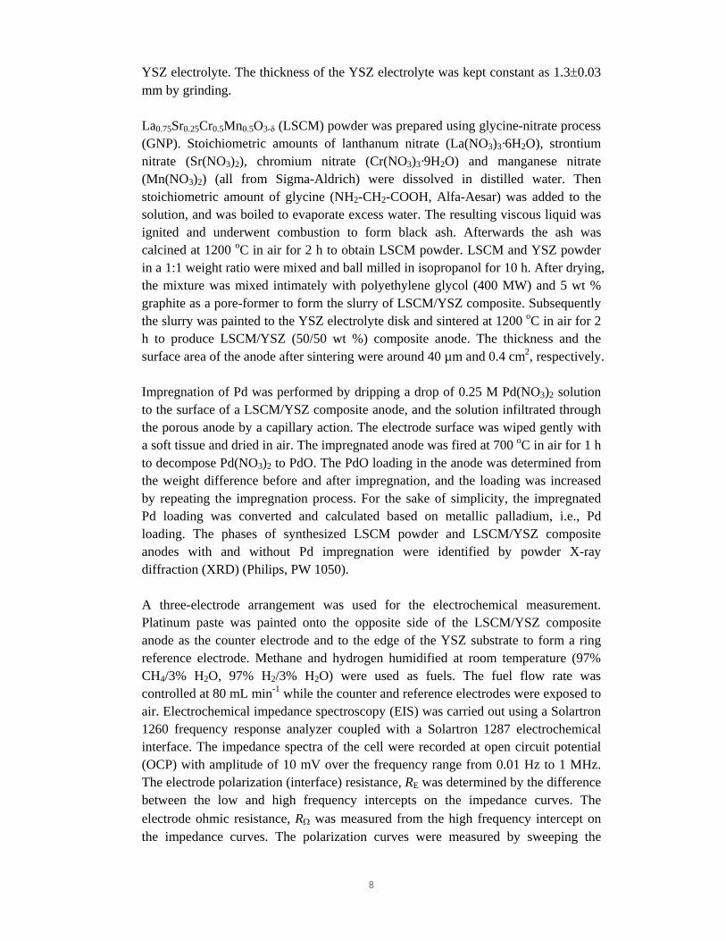
Figure 2. SEM imagines of (a-c) 0.36 mg cm-2 Pd impregnated LSCM/YSZ composite anode (a: surface before testing, b: surface after testing, c: cross-section after testing) and of (e-g) 1.02 mg cm-2 Pd impregnated LSCM/YSZ composite anode (e: surface before testing, f: surface after testing, g: cross-section after testing). Images of surface and cross-section of a pure LSCM/YSZ composite anode without Pd-impregnation are shown in (d) and (h). The anodes were tested at 800oC in wet CH4. Figure 2 shows SEM images of the surface and the cross-section of LSCM/YSZ composite anodes with different Pd loadings, before and after the electrochemical testing. After impregnation, PdO particles were uniformly distributed on the surface of the anode. The size of PdO particles of freshly prepared anodes with Pd loading of 0.36 mg cm-2 (Fig. 2a) and 1.02 mg cm-2 (Fig. 2e) was in the ranges 10 - 20 nm and 10 - 50 nm, respectively. This indicates that the size of PdO nanoparticles is related to the Pd loading. After electrochemical testing at 800 oC in wet CH4, the palladium particle size with the lower Pd loading increased to 30 - 60 nm (Fig. 2b), while it was 60 - 80 nm in the case of the higher Pd loading (Fig. 2f). In the case of higher Pd loading (1.02 mg cm-2 Pd), palladium particles are agglomerated and spread on the LSCM/YSZ particles (Fig.2f). The significant agglomeration of impregnated Pd is most likely due to the transformation of PdO to Pd, causing a rapid growth of the metallic Pd under reducing environment at high temperatures. From the images of cross-section, there are nano-sized particles distributed at the electrode/electrolyte interface regions (Fig.2c and 2g), indicating that Pd(NO3)2 solution penetrated through the porous anode. On the other hand, the surface and cross-section of LSCM/YSZ composite anodes without Pd impregnation are clean with no nano-sized particles and the particle size of LSCM/YSZ composites is in the range of ~0.5 μm
11
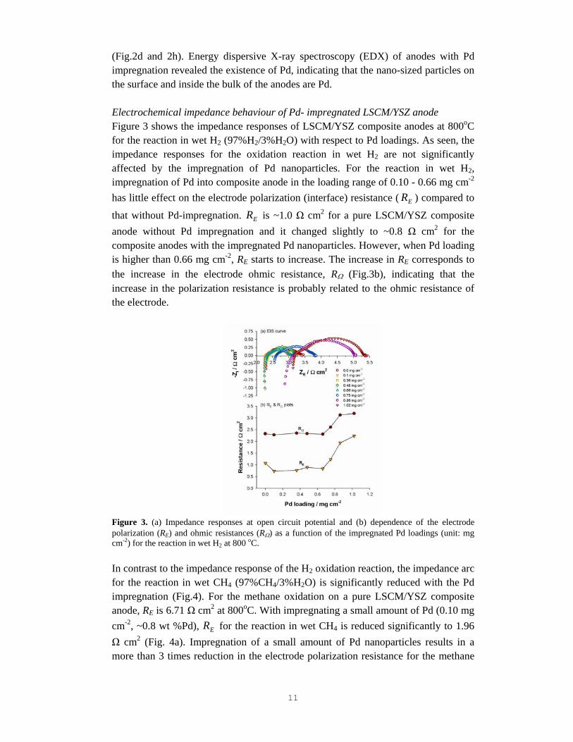
(Fig.2d and 2h). Energy dispersive X-ray spectroscopy (EDX) of anodes with Pd impregnation revealed the existence of Pd, indicating that the nano-sized particles on the surface and inside the bulk of the anodes are Pd. Electrochemical impedance behaviour of Pd- impregnated LSCM/YSZ anode Figure 3 shows the impedance responses of LSCM/YSZ composite anodes at 800oC for the reaction in wet H2 (97%H2/3%H2O) with respect to Pd loadings. As seen, the impedance responses for the oxidation reaction in wet H2 are not significantly affected by the impregnation of Pd nanoparticles. For the reaction in wet H2, impregnation of Pd into composite anode in the loading range of 0.10 - 0.66 mg cm-2 has little effect on the electrode polarization (interface) resistance ( ER ) compared to
that without Pd-impregnation. ER is ~1.0 Ω cm2 for a pure LSCM/YSZ composite anode without Pd impregnation and it changed slightly to ~0.8 Ω cm2 for the composite anodes with the impregnated Pd nanoparticles. However, when Pd loading is higher than 0.66 mg cm-2, RE starts to increase. The increase in RE corresponds to the increase in the electrode ohmic resistance, RΩ (Fig.3b), indicating that the increase in the polarization resistance is probably related to the ohmic resistance of the electrode.
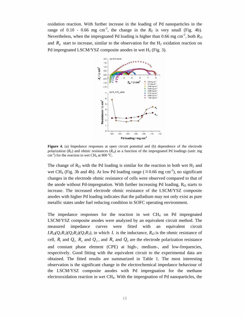
Figure 3. (a) Impedance responses at open circuit potential and (b) dependence of the electrode polarization (RE) and ohmic resistances (RΩ) as a function of the impregnated Pd loadings (unit: mg cm-2) for the reaction in wet H2 at 800 oC. In contrast to the impedance response of the H2 oxidation reaction, the impedance arc for the reaction in wet CH4 (97%CH4/3%H2O) is significantly reduced with the Pd impregnation (Fig.4). For the methane oxidation on a pure LSCM/YSZ composite anode, RE is 6.71 Ω cm2 at 800oC. With impregnating a small amount of Pd (0.10 mg cm-2, ~0.8 wt %Pd), ER for the reaction in wet CH4 is reduced significantly to 1.96 Ω cm2 (Fig. 4a). Impregnation of a small amount of Pd nanoparticles results in a more than 3 times reduction in the electrode polarization resistance for the methane
12
oxidation reaction. With further increase in the loading of Pd nanoparticles in the range of 0.10 - 0.66 mg cm-2, the change in the RE is very small (Fig. 4b). Nevertheless, when the impregnated Pd loading is higher than 0.66 mg cm-2, both RΩ and ER start to increase, similar to the observation for the H2 oxidation reaction on Pd impregnated LSCM/YSZ composite anodes in wet H2 (Fig. 3).
Figure 4. (a) Impedance responses at open circuit potential and (b) dependence of the electrode polarization (RE) and ohmic resistances (RΩ) as a function of the impregnated Pd loadings (unit: mg cm-2) for the reaction in wet CH4 at 800 oC. The change of RΩ with the Pd loading is similar for the reaction in both wet H2 and wet CH4 (Fig. 3b and 4b). At low Pd loading range (≦0.66 mg cm-2), no significant changes in the electrode ohmic resistance of cells were observed compared to that of the anode without Pd-impregnation. With further increasing Pd loading, RΩ starts to increase. The increased electrode ohmic resistance of the LSCM/YSZ composite anodes with higher Pd loading indicates that the palladium may not only exist as pure metallic states under fuel reducing condition in SOFC operating environment. The impedance responses for the reaction in wet CH4 on Pd impregnated LSCM/YSZ composite anodes were analyzed by an equivalent circuit method. The measured impedance curves were fitted with an equivalent circuit LRΩ(Q1R1)(Q2R2)(Q3R3), in which L is the inductance, RΩ is the ohmic resistance of cell, 1R and 1Q , 2R and 2Q , and 3R and 3Q are the electrode polarization resistance and constant phase element (CPE) at high-, medium-, and low-frequencies, respectively. Good fitting with the equivalent circuit to the experimental data are obtained. The fitted results are summarized in Table 1. The most interesting observation is the significant change in the electrochemical impedance behaviour of the LSCM/YSZ composite anodes with Pd impregnation for the methane electrooxidation reaction in wet CH4. With the impregnation of Pd nanoparticles, the

13
size of the impedance arc is reduced significantly. For the reaction on a 0.75 mg cm-2 Pd impregnated LSCM/YSZ composite anode, the overall RE is 1.92 Ωcm2, substantially smaller that a RE value of 6.71 Ωcm2 measured for the reaction on a pure LSCM/YSZ composite anode. Table 1. Fitted impedance results for the methane oxidation reaction in wet CH4 on LSCM/YSZ
anodes with and without Pd impregnation at 800oC.
Pd loading (mg cm-2)
Ohmic resistance (Ω cm2)
Electrode polarization resistance (Ω cm2)
RΩ High-Frequency arc
( 1R )
Medium-Frequency arc
( 2R )
Low-Frequency arc ( 3R )
0.0 2.40 0.10 2.51 4.10 0.10 2.35 0.08 1.58 0.31 0.75 2.83 0.43 1.60 0.56 1.02 3.45 1.15 2.76 0.70
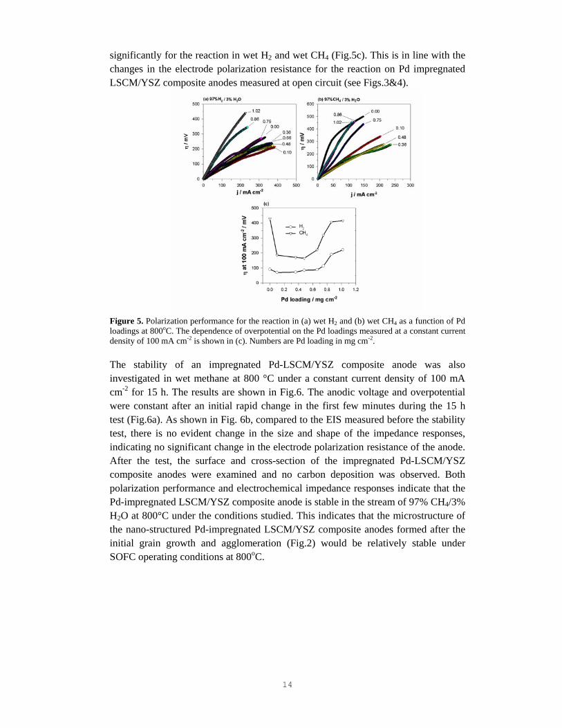
LSCM is a p-type conductor and shows limited mixed ionic and electronic conductivity under SOFC operation conditions. As shown in a previous study, the methane oxidation reaction in wet CH4 on pure LSCM/YSZ composite anodes may be controlled by the oxygen surface exchange and diffusion process, which is limited by the high energetic process of oxygen vacancy diffusion in the LSCM perovskites.9 The profound impact on the reduction of the electrode polarization impedance at low frequencies by the impregnated Pd nanoparticles indicates the promoting effect of palladium on the oxygen surface exchange and diffusion process and on the CH4 decomposition. Polarization performance and stability of Pd- impregnated LSCM/YSZ anodes The polarization performance of LSCM/YSZ composite anodes for the oxidation reaction in wet H2 and wet CH4 at 800 oC as a function of impregnated Pd loadings is shown in Fig. 5. Similar to the impedance behaviour, the effect of impregnated Pd nanoparticles is significantly different for the reaction in wet H2 and in wet CH4. Pd impregnation has little effect on the electrocatalytic activity of the LSCM/YSZ composite anodes for the oxidation reaction in wet H2 (Fig.5a). The changes in the polarization behaviour for the H2 oxidation reaction are very small for the LSCM/YSZ composite anodes with respect of the Pd loading in the range of 0.10-0.75 mgcm-2. However, the promoting effect of impregnated Pd nanoparticles is significant for the methane oxidation reaction. The overpotential decreases significantly with the impregnation of Pd nanoparticles (Fig.5b). For the methane oxidation reaction on a pure LSCM/YSZ anode, overpotential,η , was as high as 428 mV at a current density of 100 mA cm-2. After impregnation of 0.10 mg cm-2 Pd, η decreased rapidly to 185 mV, a reduction of more than twofold in the polarization potential. With further increasing of the Pd loadings, the overpotential increases
14
significantly for the reaction in wet H2 and wet CH4 (Fig.5c). This is in line with the changes in the electrode polarization resistance for the reaction on Pd impregnated LSCM/YSZ composite anodes measured at open circuit (see Figs.3&4).
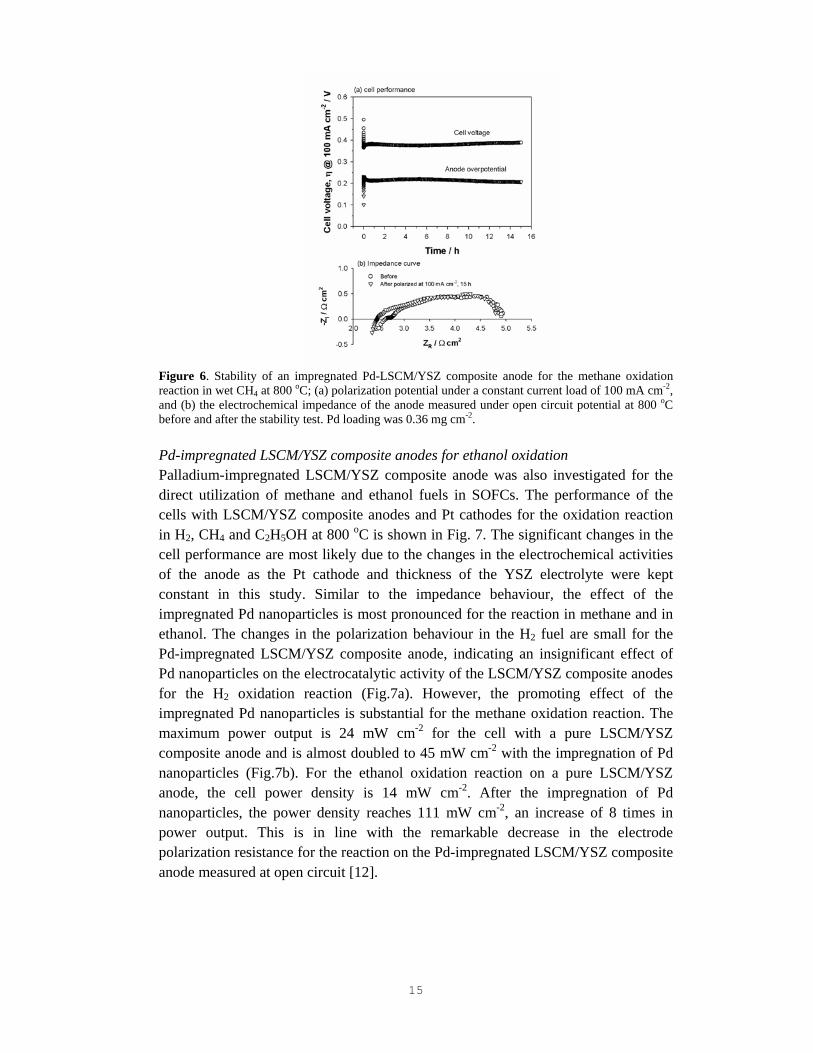
Figure 5. Polarization performance for the reaction in (a) wet H2 and (b) wet CH4 as a function of Pd loadings at 800oC. The dependence of overpotential on the Pd loadings measured at a constant current density of 100 mA cm-2 is shown in (c). Numbers are Pd loading in mg cm-2. The stability of an impregnated Pd-LSCM/YSZ composite anode was also investigated in wet methane at 800 °C under a constant current density of 100 mA cm-2 for 15 h. The results are shown in Fig.6. The anodic voltage and overpotential were constant after an initial rapid change in the first few minutes during the 15 h test (Fig.6a). As shown in Fig. 6b, compared to the EIS measured before the stability test, there is no evident change in the size and shape of the impedance responses, indicating no significant change in the electrode polarization resistance of the anode. After the test, the surface and cross-section of the impregnated Pd-LSCM/YSZ composite anodes were examined and no carbon deposition was observed. Both polarization performance and electrochemical impedance responses indicate that the Pd-impregnated LSCM/YSZ composite anode is stable in the stream of 97% CH4/3% H2O at 800°C under the conditions studied. This indicates that the microstructure of the nano-structured Pd-impregnated LSCM/YSZ composite anodes formed after the initial grain growth and agglomeration (Fig.2) would be relatively stable under SOFC operating conditions at 800oC.
15
Figure 6. Stability of an impregnated Pd-LSCM/YSZ composite anode for the methane oxidation reaction in wet CH4 at 800 oC; (a) polarization potential under a constant current load of 100 mA cm-2, and (b) the electrochemical impedance of the anode measured under open circuit potential at 800 oC before and after the stability test. Pd loading was 0.36 mg cm-2.
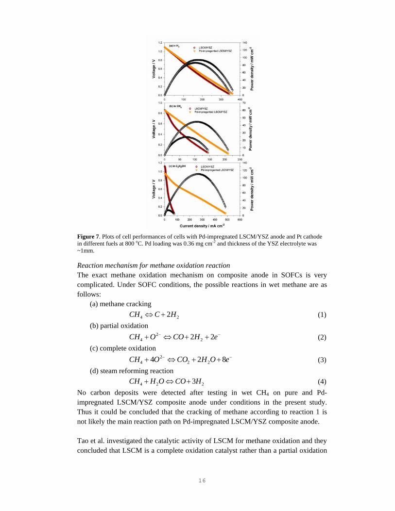
Pd-impregnated LSCM/YSZ composite anodes for ethanol oxidation Palladium-impregnated LSCM/YSZ composite anode was also investigated for the direct utilization of methane and ethanol fuels in SOFCs. The performance of the cells with LSCM/YSZ composite anodes and Pt cathodes for the oxidation reaction in H2, CH4 and C2H5OH at 800 oC is shown in Fig. 7. The significant changes in the cell performance are most likely due to the changes in the electrochemical activities of the anode as the Pt cathode and thickness of the YSZ electrolyte were kept constant in this study. Similar to the impedance behaviour, the effect of the impregnated Pd nanoparticles is most pronounced for the reaction in methane and in ethanol. The changes in the polarization behaviour in the H2 fuel are small for the Pd-impregnated LSCM/YSZ composite anode, indicating an insignificant effect of Pd nanoparticles on the electrocatalytic activity of the LSCM/YSZ composite anodes for the H2 oxidation reaction (Fig.7a). However, the promoting effect of the impregnated Pd nanoparticles is substantial for the methane oxidation reaction. The maximum power output is 24 mW cm-2 for the cell with a pure LSCM/YSZ composite anode and is almost doubled to 45 mW cm-2 with the impregnation of Pd nanoparticles (Fig.7b). For the ethanol oxidation reaction on a pure LSCM/YSZ anode, the cell power density is 14 mW cm-2. After the impregnation of Pd nanoparticles, the power density reaches 111 mW cm-2, an increase of 8 times in power output. This is in line with the remarkable decrease in the electrode polarization resistance for the reaction on the Pd-impregnated LSCM/YSZ composite anode measured at open circuit [12].
16
Figure 7. Plots of cell performances of cells with Pd-impregnated LSCM/YSZ anode and Pt cathode in different fuels at 800 oC. Pd loading was 0.36 mg cm-2 and thickness of the YSZ electrolyte was ~1mm. Reaction mechanism for methane oxidation reaction The exact methane oxidation mechanism on composite anode in SOFCs is very complicated. Under SOFC conditions, the possible reactions in wet methane are as follows:
(a) methane cracking
24 2HCCH +⇔ (1) (b) partial oxidation
−− ++⇔+ eHCOOCH 22 22
4 (2) (c) complete oxidation
−− ++⇔+ eOHCOOCH 824 222
4 (3) (d) steam reforming reaction
224 3HCOOHCH +⇔+ (4) No carbon deposits were detected after testing in wet CH4 on pure and Pd-impregnated LSCM/YSZ composite anode under conditions in the present study. Thus it could be concluded that the cracking of methane according to reaction 1 is not likely the main reaction path on Pd-impregnated LSCM/YSZ composite anode. Tao et al. investigated the catalytic activity of LSCM for methane oxidation and they concluded that LSCM is a complete oxidation catalyst rather than a partial oxidation
17
catalyst in methane oxidation as CO2 dominates CO production [13]. Hibino et al. reported that addition of a small amount of Pd (0.145 mg cm-2) to the anode in a single-chamber SOFC significantly promotes the partial oxidation of methane to H2 and CO [14]. Therefore the methane oxidation reaction on Pd-impregnated LSCM/YSZ composite anode could proceed via either complete oxidation, partial oxidation reaction path, or steam reforming followed by the electrochemical oxidation of CO and H2. Under SOFC operating condition, LSCM/YSZ composite could act as an oxygen storage/exchange reservoir. Thus, the interaction between mixed conducting LSCM/YSZ oxides and palladium metal could lead to the formation of palladium oxide such as PdO and/or nonstoichiometric PdOx on the surface of metallic Pd, i.e., the coexistence of Pd and PdO/PdOx during the methane oxidation reaction in wet CH4. The existence of PdO/PdOx on the surface of Pd appears to be supported by the weak peak of Pd3d3/2 at 342.63 eV for the reduced sample and by the increase in the electrode ohmic resistance of the LSCM/YSZ composite anodes with high Pd loadings (see Figs.3&4). The formation of PdO/PdOx on the electrode surface would increase the contact resistance between the anode and the current collector as PdO/PdOx is a semiconductor. Nabae et al.[15] studied the catalytic behaviour of Pd-Ni alloys on La0.8Sr0.2CrO3/Ce0.8Sm0.2O2 (LSC/SDC) composite anodes in dry CH4. The results suggest that the rate determining step for the reaction in dry CH4 is the decomposition of CH4 and the addition of Pd-Ni nanoparticles significantly promotes the cleavage of C-H bonds of CH4. Pure LSCM/YSZ composite anodes also show high electrode polarization resistance (Fig.4) and high overpotential losses (Fig. 5) for the reaction in wet CH4, consistent with that observed on pure LSC/SDC anodes [15]. The very large electrode polarization resistance associated with low frequencies may indicate the dominance of the surface exchange and diffusion of reactant species such as oxygen on the LSCM/YSZ composite anodes or the very low concentration of H2 for the methane oxidation reaction. Pd impregnation substantially decreases the electrode polarization resistance and the polarization losses. The promotion effect of Pd nanoparticles is particularly effective for the electrode process associated with low frequencies. The enhancing effect of Pd on the surface exchange and diffusion and the CH4 decomposition appears to be related to the existence of PdO/PdOx or the transition between Pd and PdO/PdOx on the LSCM/YSZ electrode surface. In addition, Palladium is a good catalyst for steam reforming hydrocarbons. For methane oxidation reaction in wet CH4, Pd could also promote the steam reforming of methane according to reaction 4 on Pd-impregnated LSCM/YSZ composite anodes. However, detailed studies are needed to fundamentally understand the kinetics and mechanism of the methane electrochemical oxidation reaction on nano-structured Pd-LSCM/YSZ composite anodes. The present study shows that impregnation of a relatively small amount of Pd significantly promotes the
18
electrooxidation reaction of methane and depresses the carbon deposition for the reaction in wet CH4 (97% CH4/3% H2O). The results demonstrate that Pd-impregnated LSCM/YSZ composite is a promising carbon-tolerant anode for natural gas fuel based SOFCs. Further improvement in the dispersion of Pd nanoparicles in the LSCM/YSZ composite anode is expected to enhance the activity and stability of the anode. Conclusions Pd-impregnated LSCM/YSZ composite anode was investigated as an alternative Ni-free anode for the direct utilization of methane and ethanol in SOFCs. Impregnation of a small amount of Pd (0.10 - 0.36 mg cm-2) significantly reduces the electrode polarization resistance and the polarization overpotential for the methane oxidation reaction in wet CH4 (97% CH4/3% H2O). The detailed impedance analysis shows that impregnation of Pd nanoparticles dramatically decreases the electrode process associated with low frequencies, indicating the significant promoting effect of Pd on the exchange and diffusion of oxygen species and the CH4 decomposition on the LSCM/YSZ composite anodes. It is concluded that under SOFC operating conditions, the coexistence of Pd and PdO/PdOx may facilitate the oxygen exchange and transfer and hence accelerate the decomposition or oxidation of CH4 on the LSCM/YSZ composite. Pd-impregnated LSCM/YSZ anodes also showed significantly high activity towards the ethanol oxidation reaction. However, the inherently low electrical conductivity of the LSCM oxides could be a concern for the practical application of such oxide-based anodes in SOFCs.
19
Chapter 3: Carbon tolerance of Pdimpregnated Ni/GDC
anodes of SOFCs
Background Development of high performance electrodes for solid oxide fuel cell stacks must be coincidence with disclosure in the nature and mechanism of the reactions that lead to conversion of chemical energy of the fuel to electrical energy. In the case of hydrocarbon fuels, it is well known that Ni-based anodes are not stable due to the significant carbon deposition or cracking on the Ni surface. In this study the electrochemical activity of the Ni/GDC with and without Pd impregnation was investigated in H2, CH4 and C2H5OH. The reaction process of the oxidation reaction in H2, CH4 and C2H5OH was elucidated by electrochemical impedance spectroscopy [16-19]. Experimental YSZ electrolyte discs were prepared as described above. The surface of the pellets were ground by sandpaper in order to make the surface of the electrolyte rough enough for better overlaying of the working and counter electrodes. Nickel oxide powder from Baker Company (US) and a home-made gadolinium doped ceria (G0.1DC0.9) powder were used for preparing Ni/GDC anode cermet. The cermet was prepared by mixing 65 wt% nickel oxide with 35 wt% of GDC. The cermet slurry was painted in the center of one side of the electrolyte surface with the surface area of 0.5 cm2. The painted anode electrode was sintered at 1400ºC for 2 h. Counter electrode was painted exactly opposite to the anode electrode with similar shape and surface area by using Pt paste from Metalor company (Swiss). Pt paste was also used for painting the reference electrode in the shape of a ring around the counter electrode. Distance between the counter and reference electrode was 4 mm. The painted counter and reference electrodes were baked in the furnace at 900ºC for one h in air. A diluted palladium nitrate solution (Alfa Aesar) with the concentration of 0.05 M was used for the impregnation of Pd catalyst to the Ni/GDC cermet anode. The impregnated cell was calcined at 700ºC for 1 h to remove the volatile part of the infiltrated solution and deposit Pd oxide phase in the microstructure. Before starting the electrochemical testing of the cells the Pd oxide was reduced to metallic Pd in hydrogen stream. Loading of the Pd content was estimated by calculating the weight difference of the cells before and after impregnation. After 4 times of impregnation the Pd content was reached to 0.08 mg cm-2. Measurement of the electrochemical properties of the cells was performed by using an Autolab (PGSTAT302) potentiostate. The applied frequency for the impedance
20
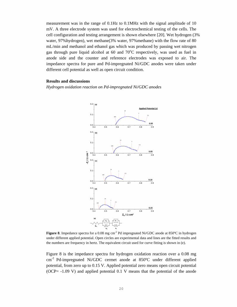
measurement was in the range of 0.1Hz to 0.1MHz with the signal amplitude of 10 mV. A three electrode system was used for electrochemical testing of the cells. The cell configuration and testing arrangement is shown elsewhere [20]. Wet hydrogen (3% water, 97%hydrogen), wet methane(3% water, 97%methane) with the flow rate of 80 mL/min and methanol and ethanol gas which was produced by passing wet nitrogen gas through pure liquid alcohol at 60 and 70oC respectively, was used as fuel in anode side and the counter and reference electrodes was exposed to air. The impedance spectra for pure and Pd-impregnated Ni/GDC anodes were taken under different cell potential as well as open circuit condition. Results and discussions Hydrogen oxidation reaction on Pd-impregnated Ni/GDC anodes
0.4 0.5 0.6 0.7 0.8 0.90.0
0.1
0.2
0.00
Applied Potential (v)
-Zi /
Ω c
m 2
ZR / Ω cm2
100
10
1
0.1
(a)
0.4 0.5 0.6 0.7 0.8 0.90.0
0.1
0.2
0.05
(b)
100
101
0.1
0.4 0.5 0.6 0.7 0.8 0.90.0
0.1
0.2
0.10
(c)
100
101
0.1
0.4 0.5 0.6 0.7 0.8 0.90.0
0.1
0.2
(e) QH
RH
QL
RL
RO
0.15
(d)
100
101
0.1
Figure 8. Impedance spectra for a 0.08 mg cm-2 Pd impregnated Ni/GDC anode at 850ºC in hydrogen under different applied potential. Open circles are experimental data and lines are the fitted results and the numbers are frequency in hertz. The equivalent circuit used for curve fitting is shown in (e). Figure 8 is the impedance spectra for hydrogen oxidation reaction over a 0.08 mg cm-2 Pd-impregnated Ni/GDC cermet anode at 850ºC under different applied potential, from zero up to 0.15 V. Applied potential zero means open circuit potential (OCP= -1.09 V) and applied potential 0.1 V means that the potential of the anode

21
with respect to the reference electrode is -0.99 V. Similar electrochemical impedance spectroscopy tests were performed on Pd impregnated Ni/GDC anodes with PdO loading of 0.02, 0.04 and 0.06 mgcm-2. At open circuit potential, RE decreases with the Pd loading and it decreased from 0.56 Ωcm2 for a pure Ni/GDC anode to 0.29 Ωcm2 for an 0.08 mg cm-2 Pd-Ni/GDC anode. The characteristics of the impedance responses also change and become separated at low and high frequencies. The separation of high and low frequency arcs is most clear on the anode with 0.08 mg cm-2 Pd. In Fig. 1 the open circles are experimental data and the lines are fitted results. In the case of a 0.08 mgcm-2 PdO impregnated Ni/GDC, applying a 0.15V potential decreases the RE from 0.26 to 0.12 Ωcm2 which is corresponding to 54% reduction in RE. The reduction in the electrode polarization resistance is due to the impregnation of Pd nanoparticles and the application of dc bias. Hydrocarbon oxidation reaction on Pd-impergnated Ni/GDC anodes
0.5 1.0 1.5 2.0 2.5 3.00.0
0.5
1.0
0.00
0.5 1.0 1.5 2.0 2.5 3.00.0
0.5
1.0
0.10
Applied Potential (v)
ZR / Ω cm 2
-Zi /
Ω c
m 2
(a)
0.5 1.0 1.5 2.0 2.5 3.00.0
0.5
1.0
0.20
0.5 1.0 1.5 2.0 2.5 3.00.0
0.5
1.0
0.30
0.6 0.7 0.8 0.9 1.0 1.1 1.2 1.3
-0.1
0.0
0.1
0.2
0.00
0.10
0.20
(b)
0.6 0.7 0.8 0.9 1.0 1.1 1.2 1.3
-0.1
0.0
0.1
0.2
0.6 0.7 0.8 0.9 1.0 1.1 1.2 1.3
-0.1
0.0
0.1
0.2
Applied Potential (v)
-Zi /
Ω c
m2
ZR / Ω cm2
Figure 9. Impedance spectra for (a) methane and (b) ethanol oxidation reaction over pure and 0.08 mgcm-2 Pd impregnated Ni/GDC anode at 850ºC under different dc bias. The green line and symbols (large arcs) are for pure Ni/GDC and red line and symbols (small arcs) are for the reactions on Pd-impregnated Ni/GDC anodes. Figure 9 shows the impedance spectra for methane and ethanol oxidation reaction over a pure and a 0.08 mg cm-2 Pd impregnated Ni/GDC anode at 850ºC under OCP and dc bias conditions. The phenomena and the trends which are observed for the reaction in methane and ethanol are quite similar to that discussed for the reaction in hydrogen. By applying dc bias the size of impedance arc decreases considerably for both pure and Pd impregnated anodes and at a potential around 0.3 v a new arc at very high frequency appears (see Fig. 9a). The application of Pd catalyst and dc bias
22
is effective also for the oxidation of methane and ethanol, indicating the enhanced activity of the Ni/GDC cermet anodes for methane and ethanol fuels. The data are preliminary but it shows that carbon tolerance of Ni/GDC anodes can be significantly enhanced by the impregnation of catalytically active Pd and by applying dc bias. Conclusions The electrochemical impedance behavior for the oxidation reaction in hydrogen, methane and ethanol over a pure and Pd-impregnated Ni/GDC anode of SOFC were studied under open circuit and dc bias conditions. The preliminary results show that the electrocatalytic activity of Ni/GDC cermet anodes for the oxidation reaction of hydrogen, methane and ethanol can be significantly increased by the addition of Pd nanoparticles and by applying dc bias. This indicates the promising potential of development of carbon tolerance Ni/GDC anodes by optimization of the impregnation of catalytic particles and operational conditions.
23
Chapter 4: Evaluation of perovskite oxides as potential
sulfur tolerant anode materials for solid oxide fuel cells
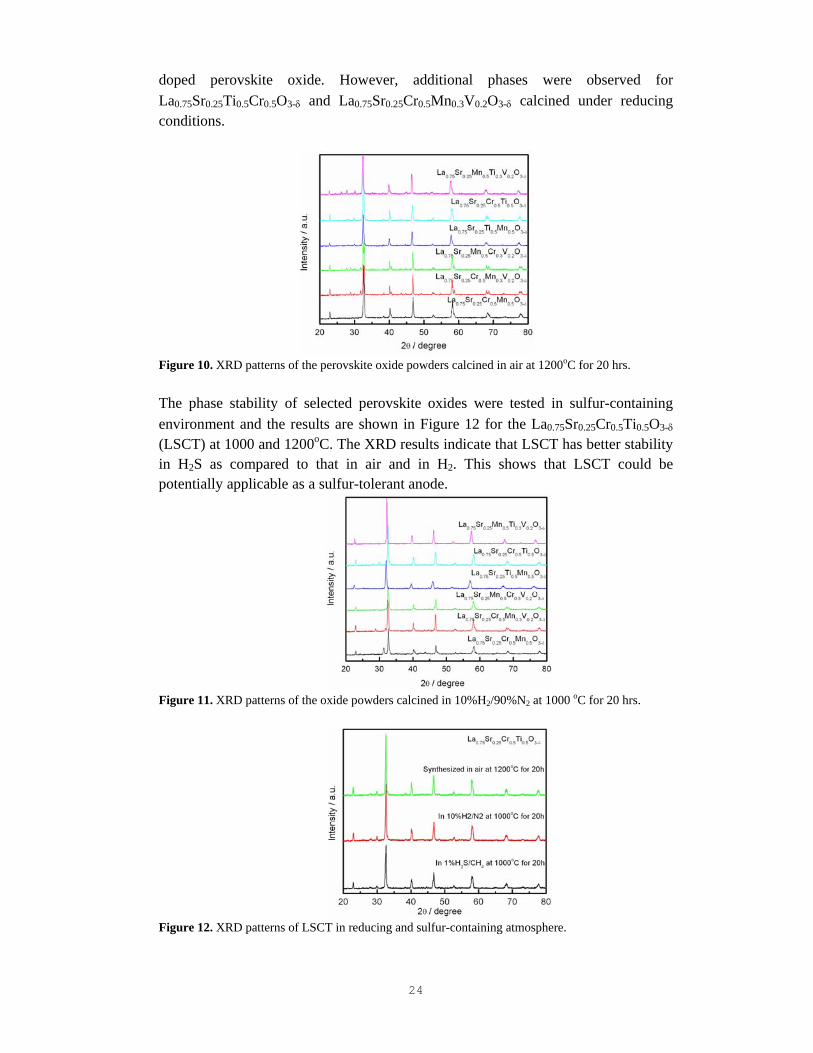
Background Ceramics with both ionic and electronic conductivity at high temperature and in a reducing environment have received increasing interest in recent years on their application as SOFCs anodes or anode components due to (1) the reduced interfacial polarization resistance by expanding the three phase boundaries; (2) the relatively good compatibility with high-quality electrolytes; and (3) potentially high sulfur tolerance as compared to metal based materials. Therefore, considerable effort has been devoted to developing various mixed electrical conductivities anode materials for the application on fuel-flexible SOFCs with sulfur tolerance [21]. In this project, vanadium and/or titanium doped strontium doped lanthanum chromate (LSC) perovskite oxides were evaluated as potential sulfur tolerant anode materials for SOFCs. Only the structural and XRD results were presented. Experimental The compositions of vanadium and/or titanium doped LSC based perovskite oxides investigated in the present project are listed below: La0.75Sr0.25Cr0.5Mn0.5O3-δ; La0.75Sr0.25Cr0.5Mn0.3V0.2O3-δ; La0.75Sr0.25Ti0.5Mn0.5O3-δ; La0.75Sr0.25Cr0.5Ti0.5O3-δ La0.75Sr0.25Ti0.3Mn0.5V0.2O3-δ; La0.75Sr0.25Cr0.3Mn0.5V0.2O3-δ Vanadate based perovskite oxides were prepared by solid state reaction method under reducing environment in order to prevent the decomposition. Titanate and chromite perovskite oxides were prepared by solid state reaction in air. The phase stability of vanadate- and titanate-doped perovskite oxide in reducing and oxidizing atmosphere and in sulfur-containing atmosphere was evaluated by X-ray diffraction (XRD, Philips MPD 1880 Diffractometer) using CuKα1 radiation (λ=1.54060) at room temperature. The phase stability of the oxides under 1% H2S-H2 fuel was carried out at 1000 and 1200oC for 20 hrs. Results Figure 10 shows the XRD spectra of selected perovskite oxides calcined at 1200oC in air for 20 hrs. It shows that chromite- and titanate-based perovskite oxide form single phase in air while second phases were observed in vanadate-doped perovskite oxides, which indicated that vanadate-doped pervoskite oxides would not be able to form a single perovskite phase in air. Figure 11 shows XRD patterns of the perovskite oxide samples calcined in reducing conditions (10%H2/90%N2) at 1000oC for 20 hrs. The calcining under reducing conditions improves the phase formation for vanadate-
24
doped perovskite oxide. However, additional phases were observed for La0.75Sr0.25Ti0.5Cr0.5O3-δ and La0.75Sr0.25Cr0.5Mn0.3V0.2O3-δ calcined under reducing conditions.
Figure 10. XRD patterns of the perovskite oxide powders calcined in air at 1200oC for 20 hrs. The phase stability of selected perovskite oxides were tested in sulfur-containing environment and the results are shown in Figure 12 for the La0.75Sr0.25Cr0.5Ti0.5O3-δ (LSCT) at 1000 and 1200oC. The XRD results indicate that LSCT has better stability in H2S as compared to that in air and in H2. This shows that LSCT could be potentially applicable as a sulfur-tolerant anode.
Figure 11. XRD patterns of the oxide powders calcined in 10%H2/90%N2 at 1000 oC for 20 hrs.
Figure 12. XRD patterns of LSCT in reducing and sulfur-containing atmosphere.

25
Figure 13 shows the XRD patterns of perovskite oxide powders after calcining in 10%H2/N2 at 1100oC for 10 hrs. The powders were pre-calcined at 800oC for 5 hrs. Second phases were found in perovskite oxide compositions except of La0.75Sr0.25Ti0.5Mn0.5O3-δ, and La0.75Sr0.25Mn0.5Ti0.3V0.2O3-δ.
Figure 13. the XRD patterns of oxide powders after baking in 10%H2/N2 at 1100oC for 10 hrs. The powder was pre-calcined at 800oC for 5 hrs Figure 14 is the XRD patterns of the powder calcined at 800oC for 5 hrs, then in 10%H2/N2 at 1100oC for 10 hrs, followed by calcination in 1%H2S/CH4 at 1100oC for 10 hrs. La0.75Sr0.25Ti0.5Mn0.5O3-δ shows the best stability under the conditions studied.
Figure 14. XRD patterns of the powder sintered in 1%H2S/CH4 at 1100oC for 10 hrs. The powders were calcined at 800oC for 5 hrs and then in 10%H2/N2 at 1100oC for 10 hrs. Conclusions
• Vanadate- and titanate-doped perovskite oxides were successfully synthesized by solid state reaction method
• Pure La0.75Sr0.25Cr0.5Mn0.5O3-δ is not stable in sulfur-containing atmosphere • The sulfur tolerance and stability of La0.75Sr0.25Cr0.5Mn0.5O3-δ powder can be
improved significantly by vanadium or titanium doping at the B-site
26
Chapter 5: Ni/GDC and Ni/YSZ cermet anodes in H2/H2S Fuels Background As shown above, the results indicate that Pd nanoparticles are very effective to promote the electrooxidation reaction of hydrogen and methane on oxides-based LSCM/YSZ anodes and enhance significantly the carbon-deposition tolerance; and the doping of LSCM by vanadium or titanium can improve the sulfur-tolerance of LSCM-based anodes. However, we also realized that the electrical conductivity of LSCM oxides is low (~1.5-2 S/cm at 800oC under reducing conditions) and low electrical conductivity would have significant limitations in the scale-up of the electrode in planar cells with large areas. Thus, to have the high electrical conductivity and high sulfur-tolerance, a more practical approach would be the modification of existing Ni-based anodes by nanoparticle impregnation methods. Ni/YSZ (Y2O3-doped ZrO2) based anodes have a very low tolerance to fuels containing H2S [1, 2, 22, 23], Grgicak et al. [24] studied the electrode behavior of Ni/YSZ in H2/H2S and found that the degradation of the electrochemical activity of Ni/YSZ was due to the conversion from metal to metal sulfide in the presence of H2S which produced large, dense metal-sulfide particles surrounded by YSZ and thus reduced the three phase boundaries. However, Cheng et al. [25] found that no sulfides were detected at elevated temperature (>500oC) when they used in situ Raman micro-spectroscopy to characterization of sulfur poisoning of Ni/YSZ anodes, and the formation of the sulfides and the changes in morphology observed in the ex situ experiments may actually occur during the slow cooling process as a result of the reactions between bulk Ni and H2S. The sulfur tolerance of Ni-based anode is not only affected by nickel itself but also by the oxide component. Sasaki et al. [22] reported that sulfur tolerance was significantly improved by substituting electrolyte component in Ni/YSZ anode with Sc2O3-doped ZrO2 (SSZ). The Gd-doped CeO2 (GDC) can also improve sulfur tolerance of SOFCs, for example, the total degradation of single cell with Ni/GDC anode is 10-12.5% in a fuel with 200-240ppm H2S for 500h at 850oC [26]. In recent years, researchers tried to improve sulfur tolerance of SOFCs via substituting nickel with copper. For example, He et al. found the cell with Cu-CeO2-YSZ anodes were able to operate at sulfur levels up to 450ppm without any appreciable loss in performance [27]. Kurokawa et al. [28] reported that impregnation of ceria nano-particles into Ni/YSZ greatly enhanced the sulfur tolerance of the Ni/YSZ anodes in humidified hydrogen fuel containing 40 ppm H2S at 700oC. This shows that addition of ceria can increase the sulfur-tolerance of the Ni-based electrodes. Thus, in this Chapter we report a detail study of the electrode behavior of pure Ni/GDC and Ni/YSZ cermet anodes in weakly humidified H2 fuel containing different levels of H2S at 800oC. The purpose of the study is to fundamentally
27
understand the effect of the oxide phase in the Ni cermet anodes towards the sulfur tolerance. Experimental Disc-type electrolyte substrates were prepared by die pressing of 8 mol% Y2O3-ZrO2 powder (YSZ, Tosoh, Japan), followed by sintering at 1500oC for 4h in air. NiO (J.T. Baker, USA) powders pre-coarsened at 700oC for 2 h in air were ball milled with gadolinium doped ceria (GDC, Fuelcellmaterials, USA) powders (NiO:GDC or YSZ = 65:35 by weight) in iso-propanol for 24 h, and 5 wt% graphite (Sigma-Aldrich) as a pore-former was also added into the mixture. After drying, the mixture was mixed with ink Vehicle (VEH, Fuelcellmaterials) to form the slurry of NiO/GDC and NiO/YSZ composite. Subsequently the slurry was painted to the YSZ electrolyte disk and sintered at 1350oC in air for 2 h to produce the composite anode. The thickness and the surface area of the anode after sintering were around 30μm and 0.5 cm2, respectively.
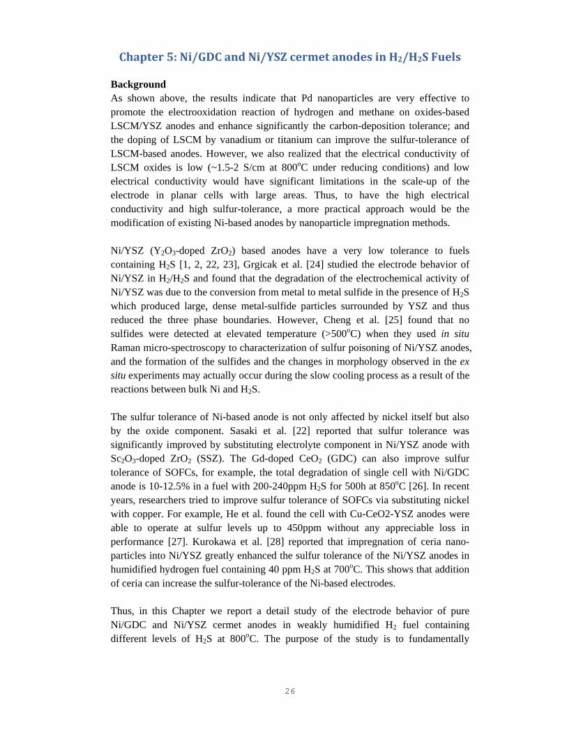
Figure 15. Schematic diagram of the cell configuration and experimental apparatus for sulfur-tolerant anode test. The preparation of the anode was similar to that described in Chapter 2. The cell configuration and scheme of experimental apparatus for sulfur-tolerant anode test are shown in Fig.15. The cell was fixed and sealed with an alumina tube via a ceramic sealant (Ceramabond 668, USA). Hydrogen and hydrogen containing different concentration of H2S humidified at room temperature (~ 3% H2O) were used as fuel while the counter and reference electrodes were exposed to static air. The fuel flow rate was 50 mL min-1. The electrode behavior of the Ni-based anodes was characterized by EIS techniques. The polarization performance was carried out under a constant anodic current of 200 mA cm-2 at 800oC. The EIS was measured at open circuit potential (OCP) at a frequency range of 100 kHz to 0.1 Hz with the signal amplitude of 10 mV. The electrode interfacial (polarization) resistance (RE) was determined by the difference between high and low frequency intercepts in the
WE
CE RE
Scrubber (KOH)
Wat
er S
atur
ator
Valves
Mass flow controllers
H2+H2S H2 N2
Gas
In
Out
Au wire
Ni/GDC
Pt electrode
Pt mesh
Ceramic sealant
Au mesh
Alumina tubes
YSZ electrolyte
Pt wire
28
impedance axis. The electrode ohmic resistance, RΩ was measured from the high frequency intercept on the impedance curves. Ni-based anodes after test in a 100 ppm H2S-H2 fuel were cooled down in N2, except for Ni/GDC anode operated in a H2 + 1000 ppm H2S fuel cooled down in the same fuel. Then, the surface of the anodes was inspected and the microstructure was examined by scanning electron microscopy (SEM, JEOL 6340F, Japan) and X-ray energy dispersion spectroscopy (EDS, Oxford, UK). Results and Discussions Oxidation reaction on Ni-based anodes in H2S –containing H2
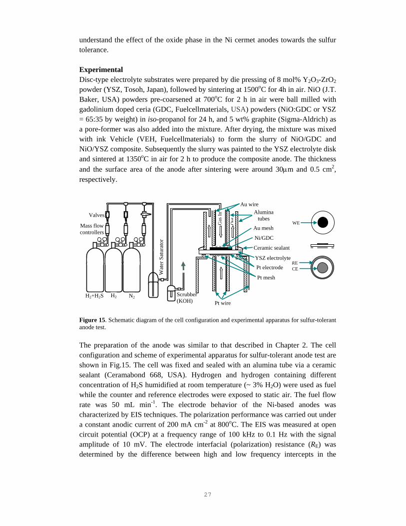
Figure 16. Impedance curves responses of Ni/GDC anodes as a function of H2S concentration, measured at open circuit condition after polarized at 200 mA cm-2 for 2 h and 800 oC. Figure 16 shows the impedance curves of Ni/GDC anodes in H2 fuel containing different H2S contents, measured at open circuit condition after polarized at 200 mA cm-2 for 2 h and 800oC. The initial RE is 0.25 Ω cm2 after polarized at 200 mA cm-2 and 800 oC in pure H2 for 2 h and increased to 0.62 Ω cm2 after polarized at 200 mA cm-2 and 800 oC for 2 h under H2S concentration of 5 ppm. After the subsequent exposed to pure H2 again and under 200 mA cm-2 for another 2 h, the RE is 0.39 Ω cm2 and did not return to the original value. This means the electrocatalytic activity of Ni/GDC in sulfur-containing H2 fuel cannot be recovered. As shown in Fig. 16, RE of the anode under H2 fuel containing x (0<x<500) ppm H2S is larger than that of the same specimen under pure H2 in the previous testing step. However, it is interesting to note that RE of the anode under H2 fuel mixture with x (x≥500) ppm H2S is smaller than that tested previously under pure H2.

29
Figure 17 is the plots of RE measured in H2 and H2S-H2 fuels after polarized at 200 mAcm-2 and 800oC f a period of 2 hrs. the data were taken from Fig.16. The plots clearly show the significant poisoning of the electrode activity by H2S. RE increases with the concentration of H2S in H2 and reaches a maximum when the H2S concentration is 200 ppm, and RE decreases again with the increase of the H2S contents in H2 fuel. On the other hand, RE increased under pure H2 when the gas was changed to H2 after tested in H2-H2S mixture. It is suggested that the sulfur poisoning effect is accumulative and becomes more severe with the increase in the H2S concentration and exposure time.
Figure 17. Plots of anode polarization resistance, RE, for H2 fuel containing H2S oxidation reaction on Ni/GDC anode as a function of H2S level, measured at open circuit condition after polarized at 200 mA cm-2 for 2 h and 800 oC. Figure 18 shows the corresponding impedance curves of Ni/YSZ anodes in H2 fuel containing x (0≤x≤1000) ppm H2S, measured at open circuit condition after polarized at 200 mA cm-2 for 2 h and 800 oC. The change of the impedance behavior of the reaction on Ni/YSZ cermet anodes is similar to that on Ni/GDC ceremt anodes. However, the magnitude of the RE measured on Ni/YSZ is significantly higher on that on Ni/GDC. For example, RE is 1.89 Ω cm2 under pure H2 and increased to 2.12 Ω cm2 after polarization at 200 mA cm-2 for 2 h and 800 oC under 5 ppm H2S-H2. Figure 19 is the corresponding plots of RE of Ni/YSZ anode as a function of H2S concentration. The plot shows the significant poisoning effect on the electrode activity of Ni/YSZ anodes by H2S. The change of RE with the concentration of H2S is similar to that observed for Ni/GDC anodes but RE reached the maximum at the H2S concentration of ~100ppm, lower than 200ppm in the case of Ni/GDC anodes. Zha et al. [1] also found that when the H2S concentration exceeded 2 ppm, RE of Ni/YSZ significantly increased and the recovery process couldn’t be completely in 2 h.
30
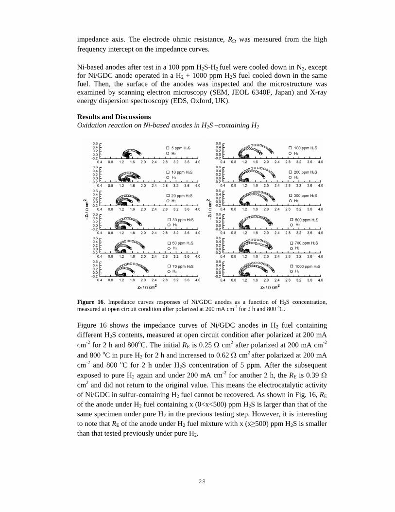
Figure 18. Impedance curves responses of Ni/YSZ anode as a function of H2S concentration, measured at open circuit condition after polarized at 200 mA cm-2 for 2 h and 800 oC.
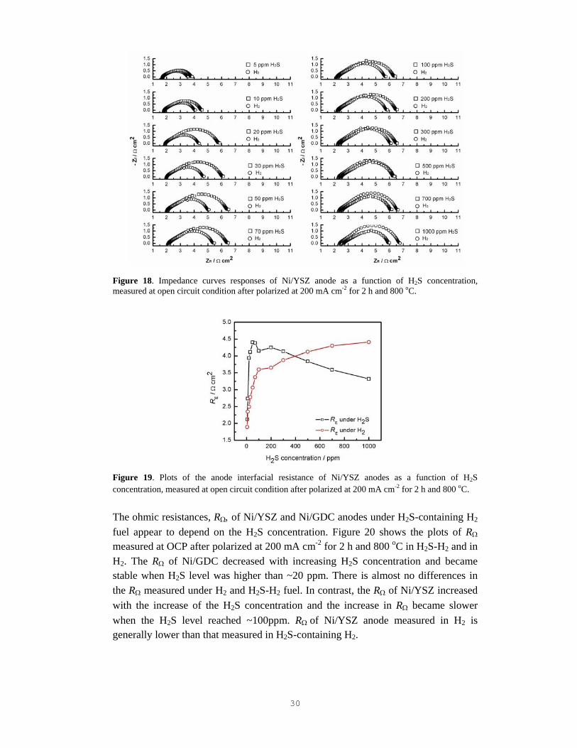
Figure 19. Plots of the anode interfacial resistance of Ni/YSZ anodes as a function of H2S concentration, measured at open circuit condition after polarized at 200 mA cm-2 for 2 h and 800 oC. The ohmic resistances, RΩ, of Ni/YSZ and Ni/GDC anodes under H2S-containing H2 fuel appear to depend on the H2S concentration. Figure 20 shows the plots of RΩ measured at OCP after polarized at 200 mA cm-2 for 2 h and 800 oC in H2S-H2 and in H2. The RΩ of Ni/GDC decreased with increasing H2S concentration and became stable when H2S level was higher than ~20 ppm. There is almost no differences in the RΩ measured under H2 and H2S-H2 fuel. In contrast, the RΩ of Ni/YSZ increased with the increase of the H2S concentration and the increase in RΩ became slower when the H2S level reached ~100ppm. RΩ of Ni/YSZ anode measured in H2 is generally lower than that measured in H2S-containing H2.
31
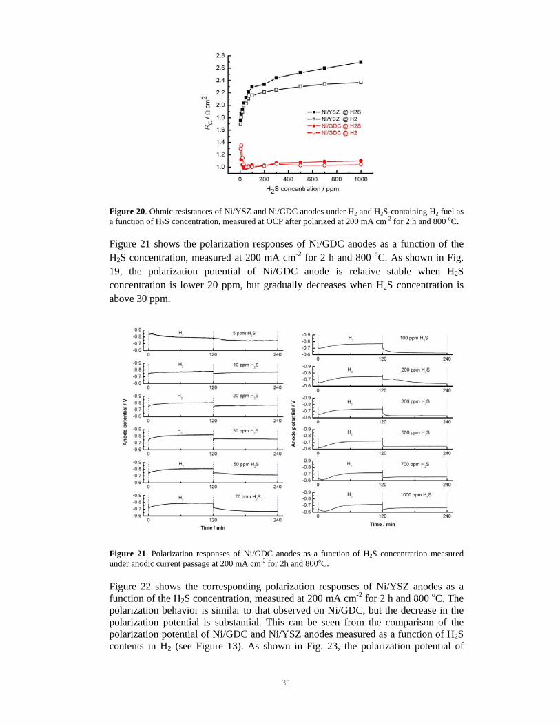
Figure 20. Ohmic resistances of Ni/YSZ and Ni/GDC anodes under H2 and H2S-containing H2 fuel as a function of H2S concentration, measured at OCP after polarized at 200 mA cm-2 for 2 h and 800 oC. Figure 21 shows the polarization responses of Ni/GDC anodes as a function of the H2S concentration, measured at 200 mA cm-2 for 2 h and 800 oC. As shown in Fig. 19, the polarization potential of Ni/GDC anode is relative stable when H2S concentration is lower 20 ppm, but gradually decreases when H2S concentration is above 30 ppm.
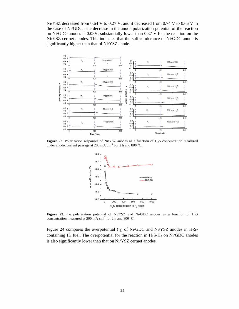
Figure 21. Polarization responses of Ni/GDC anodes as a function of H2S concentration measured under anodic current passage at 200 mA cm-2 for 2h and 800oC. Figure 22 shows the corresponding polarization responses of Ni/YSZ anodes as a function of the H2S concentration, measured at 200 mA cm-2 for 2 h and 800 oC. The polarization behavior is similar to that observed on Ni/GDC, but the decrease in the polarization potential is substantial. This can be seen from the comparison of the polarization potential of Ni/GDC and Ni/YSZ anodes measured as a function of H2S contents in H2 (see Figure 13). As shown in Fig. 23, the polarization potential of
32
Ni/YSZ decreased from 0.64 V to 0.27 V, and it decreased from 0.74 V to 0.66 V in the case of Ni/GDC. The decrease in the anode polarization potential of the reaction on Ni/GDC anodes is 0.08V, substantially lower than 0.37 V for the reaction on the Ni/YSZ cermet anodes. This indicates that the sulfur tolerance of Ni/GDC anode is significantly higher than that of Ni/YSZ anode.
Figure 22. Polarization responses of Ni/YSZ anodes as a function of H2S concentration measured under anodic current passage at 200 mA cm-2 for 2 h and 800 oC.
Figure 23. the polarization potential of Ni/YSZ and Ni/GDC anodes as a function of H2S concentration measured at 200 mA cm-2 for 2 h and 800 oC. Figure 24 compares the overpotential (η) of Ni/GDC and Ni/YSZ anodes in H2S-containing H2 fuel. The overpotential for the reaction in H2S-H2 on Ni/GDC anodes is also significantly lower than that on Ni/YSZ cermet anodes.
33
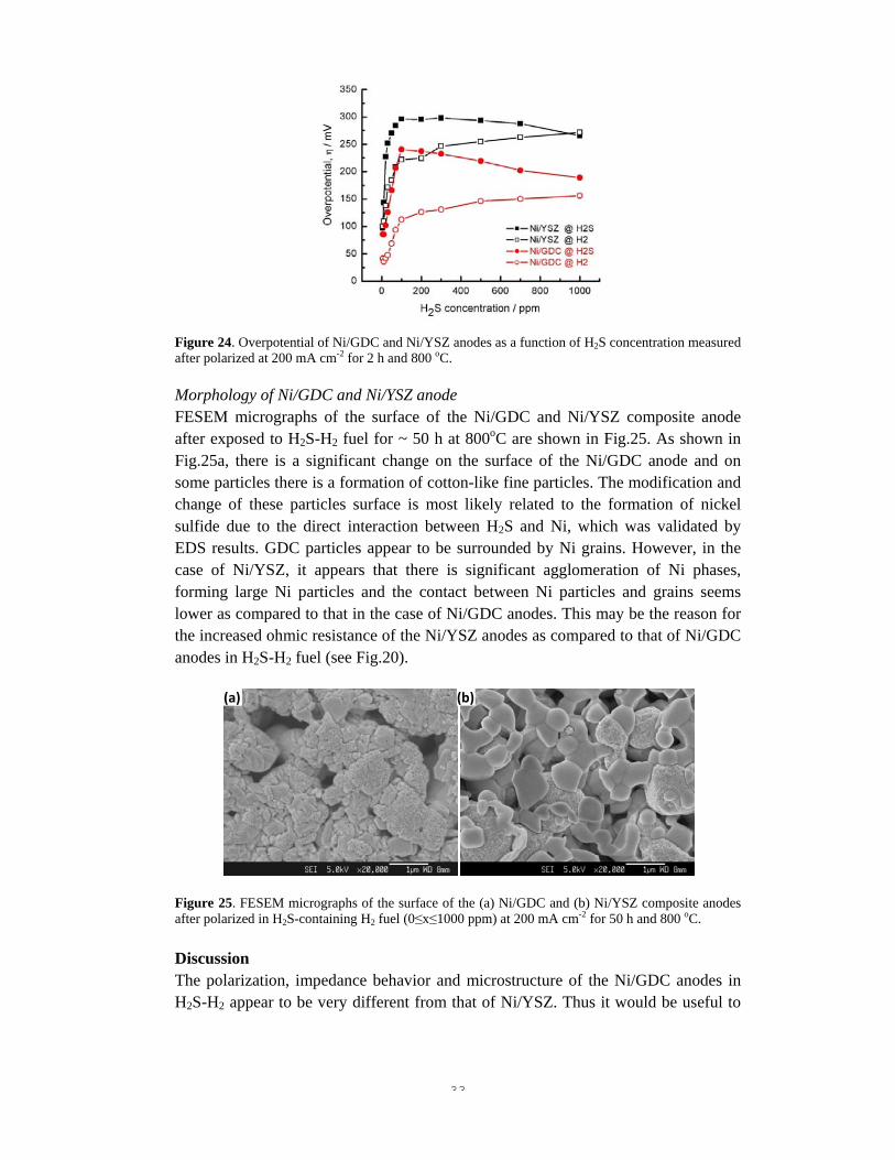
Figure 24. Overpotential of Ni/GDC and Ni/YSZ anodes as a function of H2S concentration measured after polarized at 200 mA cm-2 for 2 h and 800 oC. Morphology of Ni/GDC and Ni/YSZ anode FESEM micrographs of the surface of the Ni/GDC and Ni/YSZ composite anode after exposed to H2S-H2 fuel for ~ 50 h at 800oC are shown in Fig.25. As shown in Fig.25a, there is a significant change on the surface of the Ni/GDC anode and on some particles there is a formation of cotton-like fine particles. The modification and change of these particles surface is most likely related to the formation of nickel sulfide due to the direct interaction between H2S and Ni, which was validated by EDS results. GDC particles appear to be surrounded by Ni grains. However, in the case of Ni/YSZ, it appears that there is significant agglomeration of Ni phases, forming large Ni particles and the contact between Ni particles and grains seems lower as compared to that in the case of Ni/GDC anodes. This may be the reason for the increased ohmic resistance of the Ni/YSZ anodes as compared to that of Ni/GDC anodes in H2S-H2 fuel (see Fig.20).
Figure 25. FESEM micrographs of the surface of the (a) Ni/GDC and (b) Ni/YSZ composite anodes after polarized in H2S-containing H2 fuel (0≤x≤1000 ppm) at 200 mA cm-2 for 50 h and 800 oC. Discussion The polarization, impedance behavior and microstructure of the Ni/GDC anodes in H2S-H2 appear to be very different from that of Ni/YSZ. Thus it would be useful to
(b)(a)
34
examine the Ce-O-S phase diagram [29]. The partial pressures of O2 and S2 in the system are determined by assuming that the following reactions are in equilibrium:
H2 + 1/2O2 ↔ H2O H2 + 1/2S2 ↔ H2S
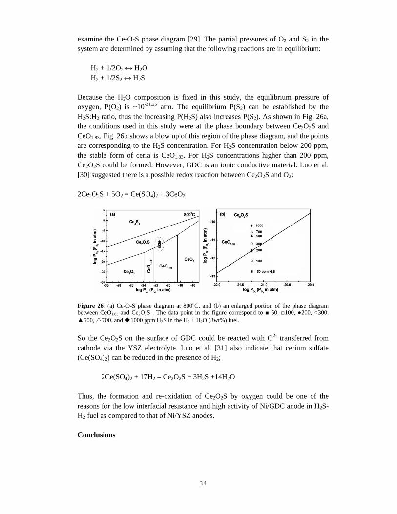
Because the H2O composition is fixed in this study, the equilibrium pressure of oxygen, P(O2) is ~10-21.25 atm. The equilibrium P(S2) can be established by the H2S:H2 ratio, thus the increasing P(H2S) also increases P(S2). As shown in Fig. 26a, the conditions used in this study were at the phase boundary between Ce2O2S and CeO1.83. Fig. 26b shows a blow up of this region of the phase diagram, and the points are corresponding to the H2S concentration. For H2S concentration below 200 ppm, the stable form of ceria is CeO1.83. For H2S concentrations higher than 200 ppm, Ce2O2S could be formed. However, GDC is an ionic conductive material. Luo et al. [30] suggested there is a possible redox reaction between Ce2O2S and O2: 2Ce2O2S + 5O2 = Ce(SO4)2 + 3CeO2
Figure 26. (a) Ce-O-S phase diagram at 800oC, and (b) an enlarged portion of the phase diagram between CeO1.83 and Ce2O2S . The data point in the figure correspond to 50, 100, 200, 300, 500, 700, and 1000 ppm H2S in the H2 + H2O (3wt%) fuel. So the Ce2O2S on the surface of GDC could be reacted with O2- transferred from cathode via the YSZ electrolyte. Luo et al. [31] also indicate that cerium sulfate (Ce(SO4)2) can be reduced in the presence of H2;
2Ce(SO4)2 + 17H2 = Ce2O2S + 3H2S +14H2O Thus, the formation and re-oxidation of Ce2O2S by oxygen could be one of the reasons for the low interfacial resistance and high activity of Ni/GDC anode in H2S-H2 fuel as compared to that of Ni/YSZ anodes. Conclusions
35
• The interfacial resistance of Ni/GDC and Ni/YSZ anodes increased with the increase H2S concentration and the increase in the electrode interface resistance is significantly higher for the reaction on Ni/YSZ anodes.
• The ohmic resistances of Ni/YSZ anodes increased with the increase H2S concentration; in contrast, the ohmic resistances of Ni/GDC anodes decreased with the increase H2S concentration.
• The overpotential of Ni/GDC anode is significantly lower than that of Ni/YSZ under a H2S-containing H2 fuel.
• The higher sulfur tolerance of Ni/GDC cermet anodes is probably related to the formation and re-oxidation of Ce2O2S due to the reaction between GDC particles and H2S, which could partially reduce the poisoning effect of H2S on Ni.
36
Chapter 6: Sulfur tolerance of Pdimpregnated Ni/GDC anodes Background Though the sulfur tolerance of Ni/GDC anode is higher than that of Ni/YSZ anode, the degradation of Ni/GDC anode under a fuel containing H2S is still serious and problematic. As shown in previous Chapters, impregnated Pd nanoparticles significantly decrease the electrode polarization resistance, indicating the significant promoting effect of Pd on the oxidation reaction of H2, CH4 and C2H5OH on the LSCM/YSZ and Ni/GDC anodes. Thus, it is anticipated that impregnated Pd nanoparticles could also promote the activity and stability of Ni/GDC anodes in H2S-H2 fuels. In this Chapter, the activity and sulfur-tolerance of Pd impregnated Ni/GDC cermet anodes were investigated in H2S-H2 fuels at 800oC. Experimental Ni/GDC electrodes were impregnated by placing a droplet of palladium nitrate solution (Pd(NO3)2·6H2O, Aldrich-Sigma) with concentration of 0.2 mol L-1 on the surface of the anode and the solution infiltrated into the porous coating by a capillary force. Excess solution was removed with a soft tissue, followed by calcination at 800 ºC for 1 h. The loading of impregnated PdO was increased by repeating the impregnation process. The impregnated PdO loading was obtained by the measurement of the weight before and after the Pd-impregnation treatment. NiO/GDC electrodes with 0, 0.092, 0.17, 0.224 and 0.16 mgcm-2 PdO loading were selected for the electrochemical testing, and were designated as Ni/GDC, Ni/GDC-Pd-1, Ni/GDC-Pd-2, Ni/GDC-Pd-3 and Ni/GDC-Pd-4, respectively, for the purpose of simplicity. The electrochemical measurement of Ni/GDC based anodes with/without Pd impregnation was carried out in H2S-H2 fuels at 800oC and the long-term stability of the Pd-impregnated Ni/GDC anodes was investigated in a 100 ppm H2S-H2 fuel at 800oC. The microstructure of the anodes cooling down in N2 was examined by FESEM (JEOL 6340F, Japan). Results Figure 27 shows the impedance curves of Pd-impregnated Ni/GDC anodes in H2S-containing H2 fuel, measured at open circuit condition after polarized at 200 mA cm-2 for 2 h and 800 oC. The initial RE after polarized at 200 mAcm-2 in pure H2 for 2 hrs was 0.22 Ωcm2, and it increased to 0.48 Ωcm2 after polarized for 2 hrs in 5ppm H2S-H2 fuel. Nevertheless, the impedance behavior is similar to that observed on pure Ni/GDC.

37
Figure 27. Impedance curves responses of Pd impregnated Ni/GDC anodes as a function of H2S concentration, measured at open circuit condition after polarized at 200 mA cm-2 for 2 h and 800 oC.
Figure 28. Polarization responses of Pd-impregnated Ni/GDC anodes as a function of H2S concentration measured under anodic current passage at 200 mA cm-2 for 2 h and 800 oC. Figure 28 is the polarization performance of Pd-impregnated Ni/GDC anode as a function of the H2S concentration, measured at 200 mA cm-2 for 2 h and 800 oC. The polarization potential of PdO-impregnated Ni/GDC anode is relative stable when H2S concentration is lower 50 ppm, the polarization potential increased slightly when H2S concentration is in the range from 50 ppm to 300 ppm. The effect of hydrogen sulfur concentration on the polarization potential of Pd-impregnated Ni/GDC anode

38
is different from that on Ni/GDC anode. Pd-impregnated Ni/GDC anodes exhibit a much higher polarization performance as compared to that of pure Ni/GDC. The better performance of the Pd-impregnated Ni/GDC is also indicated by the low η of PdO-impregnated Ni/GDC anodes in H2 and H2S-H2 fuels (Figure 29). When the H2S concentration is in the range 30 ~ 100 ppm, η of the Pd-impregnated Ni/GDC anode also increases with the increase of H2S concentration. However, the increase rate of PdO-impregnated Ni/GDC anode is significantly lower than that of Ni/GDC anode. This is consistent with that of the impedance behavior.
Figure 29. Overpotential of Ni/GDC and Pd impregnated Ni/GDC anodes as a function of H2S concentration measured after anodic current passage at 200 mA cm-2 for 2 h and 800 oC. Data were taken from Fig.28. Figure 30 shows the polarization performance stability of Ni/GDC anodes with/without Pd-impregnation tested in a 100 ppm H2S-H2 fuel at 200 mA cm-2 and 800 oC for 50 h. As shown in Fig. 30a, there is a rapid decrease of the polarization potential after introducing 100 ppm H2S in H2 for the reaction on the pure Ni/GDC anodes. The anode potential changed from 0.83 V to 0.63 V in a period of ~ 10 h, a degradation of 200 mV.
(a) (b)
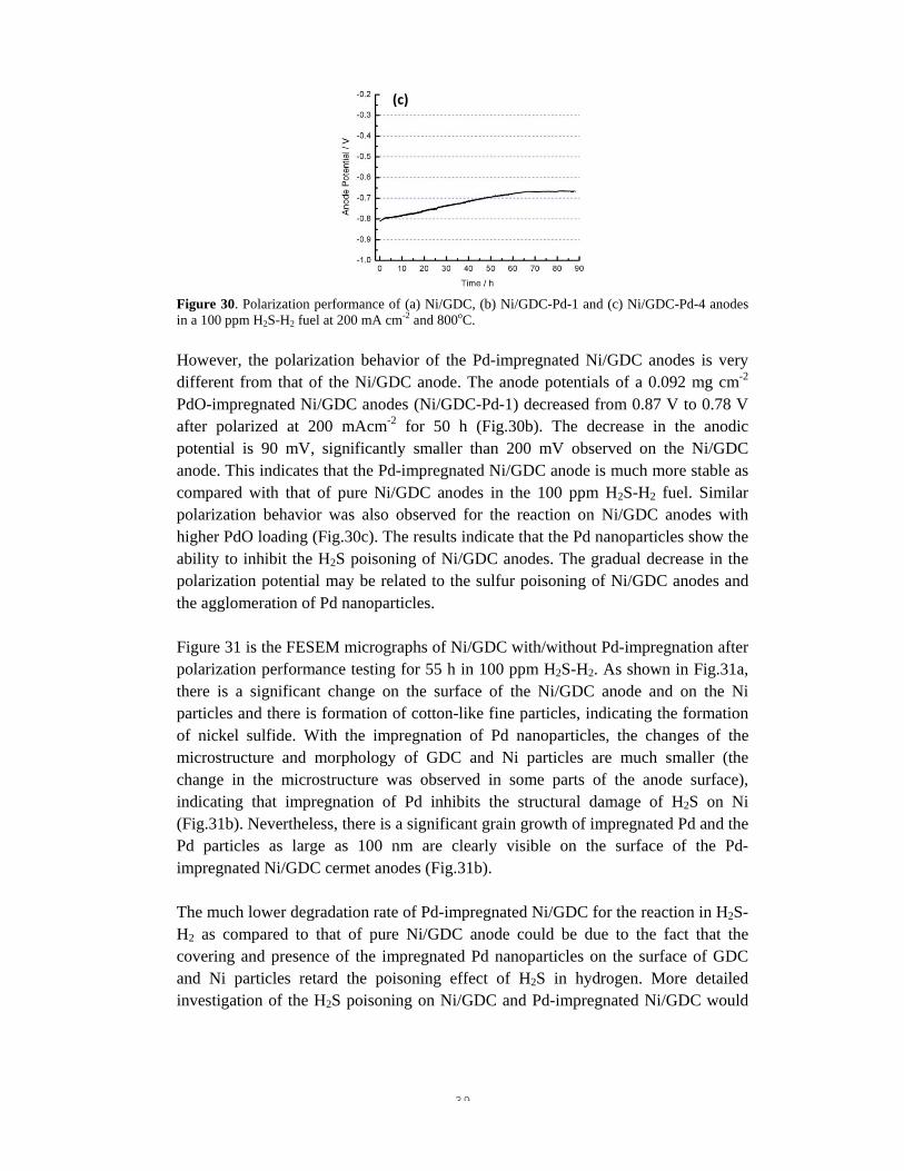
39
Figure 30. Polarization performance of (a) Ni/GDC, (b) Ni/GDC-Pd-1 and (c) Ni/GDC-Pd-4 anodes in a 100 ppm H2S-H2 fuel at 200 mA cm-2 and 800oC. However, the polarization behavior of the Pd-impregnated Ni/GDC anodes is very different from that of the Ni/GDC anode. The anode potentials of a 0.092 mg cm-2 PdO-impregnated Ni/GDC anodes (Ni/GDC-Pd-1) decreased from 0.87 V to 0.78 V after polarized at 200 mAcm-2 for 50 h (Fig.30b). The decrease in the anodic potential is 90 mV, significantly smaller than 200 mV observed on the Ni/GDC anode. This indicates that the Pd-impregnated Ni/GDC anode is much more stable as compared with that of pure Ni/GDC anodes in the 100 ppm H2S-H2 fuel. Similar polarization behavior was also observed for the reaction on Ni/GDC anodes with higher PdO loading (Fig.30c). The results indicate that the Pd nanoparticles show the ability to inhibit the H2S poisoning of Ni/GDC anodes. The gradual decrease in the polarization potential may be related to the sulfur poisoning of Ni/GDC anodes and the agglomeration of Pd nanoparticles. Figure 31 is the FESEM micrographs of Ni/GDC with/without Pd-impregnation after polarization performance testing for 55 h in 100 ppm H2S-H2. As shown in Fig.31a, there is a significant change on the surface of the Ni/GDC anode and on the Ni particles and there is formation of cotton-like fine particles, indicating the formation of nickel sulfide. With the impregnation of Pd nanoparticles, the changes of the microstructure and morphology of GDC and Ni particles are much smaller (the change in the microstructure was observed in some parts of the anode surface), indicating that impregnation of Pd inhibits the structural damage of H2S on Ni (Fig.31b). Nevertheless, there is a significant grain growth of impregnated Pd and the Pd particles as large as 100 nm are clearly visible on the surface of the Pd-impregnated Ni/GDC cermet anodes (Fig.31b). The much lower degradation rate of Pd-impregnated Ni/GDC for the reaction in H2S-H2 as compared to that of pure Ni/GDC anode could be due to the fact that the covering and presence of the impregnated Pd nanoparticles on the surface of GDC and Ni particles retard the poisoning effect of H2S in hydrogen. More detailed investigation of the H2S poisoning on Ni/GDC and Pd-impregnated Ni/GDC would
(c)

40
be needed to fundamentally understand the promotion effect of Pd nnaoparticles in reducing the H2S poisoning effect on Ni/GDC anodes.
Figure 31. FESEM micrographs of (a) Ni/GDC, (b) Ni/GDC-Pd-2 anodes after polarization performance testing in 100 ppm H2S-H2 fuel at 800oC for 55 h. One of the explanations for the promotion effect of PdO may be related to the equilibrium and reversibility between Pd4S and Pd when Pd is exposed to a H2S-containing environment at temperature above 764oC, according to Iyoha et al.[32]:
Pd4S + H2 ↔ 4Pd + H2S Conclusions The effect of H2S on the electrode behavior of Pd-impregnated Ni/GDC anodes in H2S-H2 fuel was investigated in details. The results show that the impregnated PdO nanoparticles reduce significantly the electrode polarization resistance and enhance the stability of the polarization performance of the Ni/GDC anodes. The infiltrated nano-sized PdO particles may effectively inhibit the reaction between sulfur and nickel and GDC particles, reducing the poisoning effect of H2S on the activity and structure of Ni/GDC anodes.
(a) (b)
41
Chapter 7: Sulfur tolerance of GDC and PdCeO2 impregnated Ni/GDC anodes
Background As shown in Chapter 6, the sulfur tolerance of Ni/GDC cermet anode is improved significantly by Pd impregnation. However, the agglomeration of Pd nanoparticles is still a concern and the stability of the Pd-impregnated Ni/GDC anodes needs to be improved. Thus, co-impregnation of Pd and CeO2 may improve the thermal stability of Pd and enhance the performance activity and stability of Ni/GDC anodes in H2S-H2. Here the GDC and Pd-CeO2 impregnation systems were investigated to improve the stability and activity of the impregnated Ni/GDC cermet anodes.
Experimental Ni/GDC electrodes were impregnated by GDC and Pd-CeO2 and the procedure was the same as that of Pd impregnation. NiO/GDC electrodes were impregnated with 0.194, 0.288 and 0.542 mg cm-2 GDC and designated as Ni/GDC-GDC-1, Ni/GDC-GDC-2 and Ni/GDC-GDC-3, respectively. Pd-CeO2 impregnation of Ni/GDC electrodes was carried out by placing a droplet of mixed solution of palladium nitrate (Pd(NO3)2·6H2O, Aldrich-Sigma) and cerium nitrate solution (Ce(NO3)·xH2O, Aldrich-Sigma) with metal ion concentration of 0.2 mol L-1 on the surface of the anode and the solution infiltrated into the porous coating by a capillary force. The impregnated anodes were heated at 800ºC for 1 h. The loading of impregnated Pd-CeO2 was 0.17 mgcm-2. Results and discussion GDC-impregnated Ni/GDC anodes The impedance studies of the oxidation reaction in H2 and 100 ppm H2S-H2 at 800oC indicate that GDC-impregnated Ni/GDC cermet anode is significantly active as compared to that of pure Ni/GDC anodes. For example, in the case of Ni/GDC-GDC-1, RE is 0.10 Ω cm2 at 800 ºC, half of the RE value of 0.28 Ω cm2 for the reaction on a pure Ni/GDC anode. The high performance of GDC-impregnated Ni/GDC anodes is also demonstrated by the polarization performance. Figure 32 is the polarization performance stability of GDC-impregnated Ni/GDC anodes tested in 100 ppm H2S-H2 fuel at 200 mAcm-2 and 800oC for 50 h. As shown in Fig.32a, there is a gradual decrease of the polarization potential after introducing 100 ppm H2S in H2. The anode potential changed from 0.885 V to 0.830 V in a period of ~30 h, a degradation of 55 mV in the polarization potential. The degradation of Ni/GDC-GDC-1 is lower than that of the pure Ni/GDC and Pd-impregnated Ni/GDC-Pd anodes under identical testing conditions.
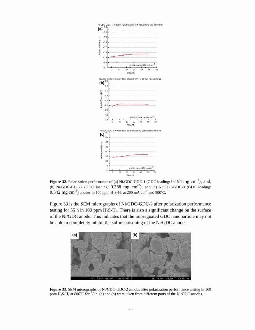
42
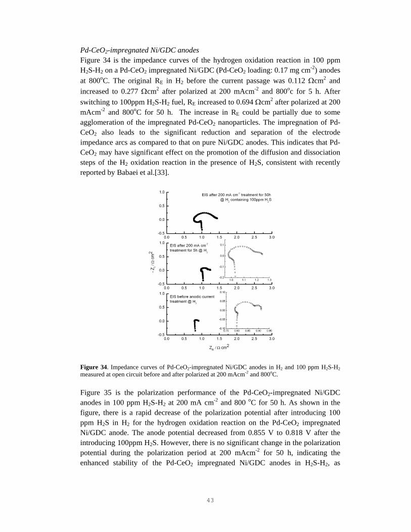
Figure 32. Polarization performance of (a) Ni/GDC-GDC-1 (GDC loading: 0.194 mg cm-2), and, (b) Ni/GDC-GDC-2 (GDC loading: 0.288 mg cm-2), and (c) Ni/GDC-GDC-3 (GDC loading: 0.542 mg cm-2) anodes in 100 ppm H2S-H2 at 200 mA cm-2 and 800oC. Figure 33 is the SEM micrographs of Ni/GDC-GDC-2 after polarization performance testing for 55 h in 100 ppm H2S-H2. There is also a significant change on the surface of the Ni/GDC anode. This indicates that the impregnated GDC nanoparticle may not be able to completely inhibit the sulfur-poisoning of the Ni/GDC anodes.
Figure 33. SEM micrographs of Ni/GDC-GDC-2 anodes after polarization performance testing in 100 ppm H2S-H2 at 800oC for 55 h. (a) and (b) were taken from different parts of the Ni/GDC anodes.
(a)
(b)
(c)
(a) (b)
43
Pd-CeO2-impregnated Ni/GDC anodes Figure 34 is the impedance curves of the hydrogen oxidation reaction in 100 ppm H2S-H2 on a Pd-CeO2 impregnated Ni/GDC (Pd-CeO2 loading: 0.17 mg cm-2) anodes at 800oC. The original RE in H2 before the current passage was 0.112 Ωcm2 and increased to 0.277 Ωcm2 after polarized at 200 mAcm-2 and 800oc for 5 h. After switching to 100ppm H2S-H2 fuel, RE increased to 0.694 Ωcm2 after polarized at 200 mAcm-2 and 800oC for 50 h. The increase in RE could be partially due to some agglomeration of the impregnated Pd-CeO2 nanoparticles. The impregnation of Pd-CeO2 also leads to the significant reduction and separation of the electrode impedance arcs as compared to that on pure Ni/GDC anodes. This indicates that Pd-CeO2 may have significant effect on the promotion of the diffusion and dissociation steps of the H2 oxidation reaction in the presence of H2S, consistent with recently reported by Babaei et al.[33].
Figure 34. Impedance curves of Pd-CeO2-impregnated Ni/GDC anodes in H2 and 100 ppm H2S-H2 measured at open circuit before and after polarized at 200 mAcm-2 and 800oC. Figure 35 is the polarization performance of the Pd-CeO2-impregnated Ni/GDC anodes in 100 ppm H2S-H2 at 200 mA cm-2 and 800 oC for 50 h. As shown in the figure, there is a rapid decrease of the polarization potential after introducing 100 ppm H2S in H2 for the hydrogen oxidation reaction on the Pd-CeO2 impregnated Ni/GDC anode. The anode potential decreased from 0.855 V to 0.818 V after the introducing 100ppm H2S. However, there is no significant change in the polarization potential during the polarization period at 200 mAcm-2 for 50 h, indicating the enhanced stability of the Pd-CeO2 impregnated Ni/GDC anodes in H2S-H2, as
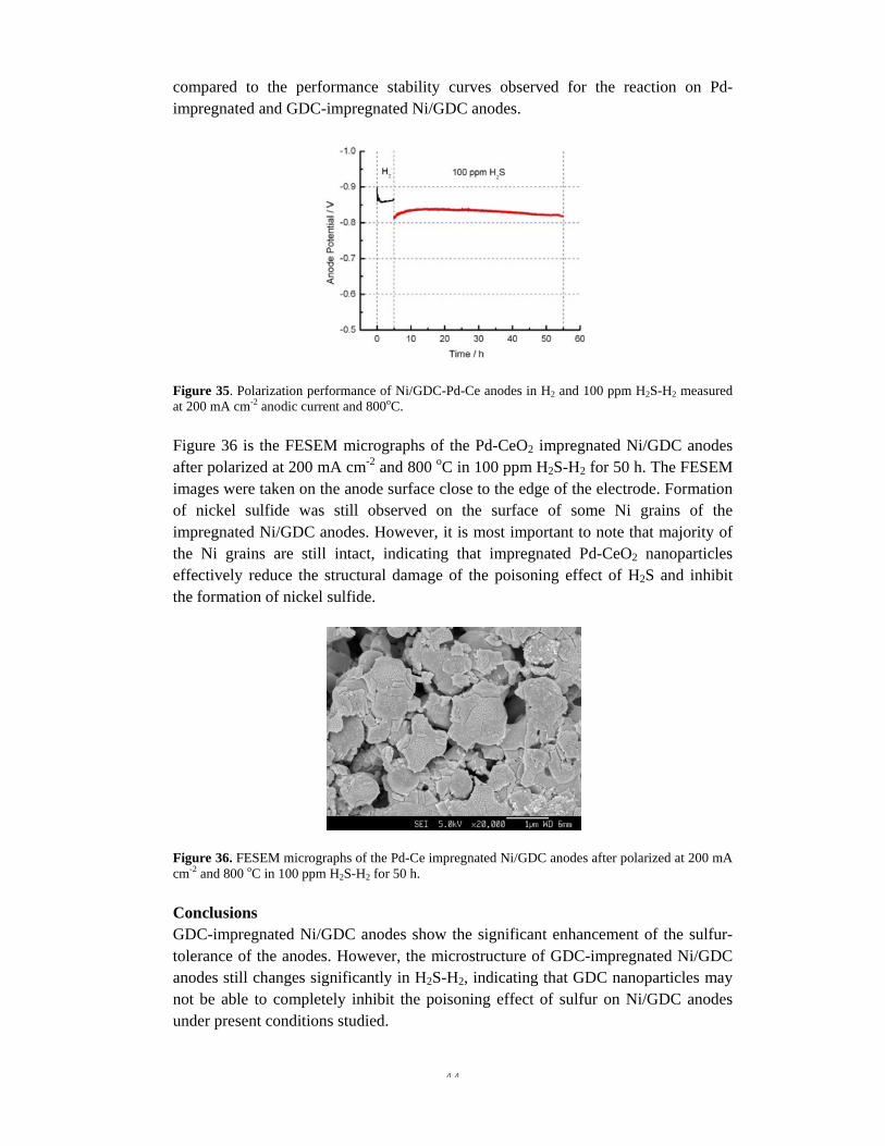
44
compared to the performance stability curves observed for the reaction on Pd-impregnated and GDC-impregnated Ni/GDC anodes.
Figure 35. Polarization performance of Ni/GDC-Pd-Ce anodes in H2 and 100 ppm H2S-H2 measured at 200 mA cm-2 anodic current and 800oC.
Figure 36 is the FESEM micrographs of the Pd-CeO2 impregnated Ni/GDC anodes after polarized at 200 mA cm-2 and 800 oC in 100 ppm H2S-H2 for 50 h. The FESEM images were taken on the anode surface close to the edge of the electrode. Formation of nickel sulfide was still observed on the surface of some Ni grains of the impregnated Ni/GDC anodes. However, it is most important to note that majority of the Ni grains are still intact, indicating that impregnated Pd-CeO2 nanoparticles effectively reduce the structural damage of the poisoning effect of H2S and inhibit the formation of nickel sulfide.
Figure 36. FESEM micrographs of the Pd-Ce impregnated Ni/GDC anodes after polarized at 200 mA cm-2 and 800 oC in 100 ppm H2S-H2 for 50 h. Conclusions GDC-impregnated Ni/GDC anodes show the significant enhancement of the sulfur-tolerance of the anodes. However, the microstructure of GDC-impregnated Ni/GDC anodes still changes significantly in H2S-H2, indicating that GDC nanoparticles may not be able to completely inhibit the poisoning effect of sulfur on Ni/GDC anodes under present conditions studied.

45
Co-impregnation of Pd-CeO2 was found to be most effective to enhance the activity of the Ni/GDC anodes for the hydrogen oxidation reaction in H2S-H2 and the polarization performance is stable under the condition of 100 ppm H2S-H2 and 200 mAcm-2 at 800oc for 50 hrs. Most important, the SEM results indicate that the impergnated Pd-CeO2 nanoparticles are effective to retard the poisoning effect of sulfur on the microstructure of Ni/GDC anodes, as compared the inhibiting effect of impregnation of Pd or GDC nanoparticles separately.
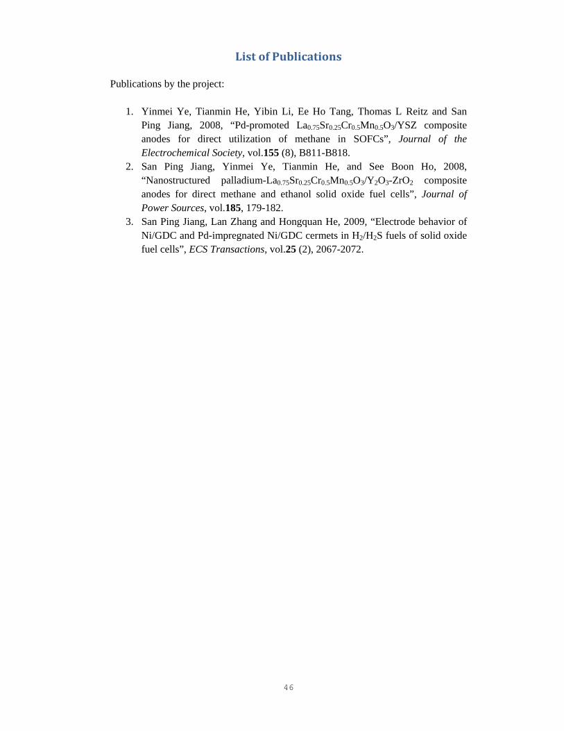
46
List of Publications Publications by the project:
1. Yinmei Ye, Tianmin He, Yibin Li, Ee Ho Tang, Thomas L Reitz and San Ping Jiang, 2008, “Pd-promoted La0.75Sr0.25Cr0.5Mn0.5O3/YSZ composite anodes for direct utilization of methane in SOFCs”, Journal of the Electrochemical Society, vol.155 (8), B811-B818.
2. San Ping Jiang, Yinmei Ye, Tianmin He, and See Boon Ho, 2008, “Nanostructured palladium-La0.75Sr0.25Cr0.5Mn0.5O3/Y2O3-ZrO2 composite anodes for direct methane and ethanol solid oxide fuel cells”, Journal of Power Sources, vol.185, 179-182.
3. San Ping Jiang, Lan Zhang and Hongquan He, 2009, “Electrode behavior of Ni/GDC and Pd-impregnated Ni/GDC cermets in H2/H2S fuels of solid oxide fuel cells”, ECS Transactions, vol.25 (2), 2067-2072.
47
References:
1. S. W. Zha, Z. Cheng, M. L. Liu, Journal of the Electrochemical Society 154 (2007) B201‐B206. 2. Y. Matsuzaki, I. Yasuda, Solid State Ionics 132 (2000) 261‐269. 3. M. L. Toebes, J. H. Bitter, A. J. van Dillen, K. P. de Jong, Catalysis Today 76 (2002) 33‐42. 4. J. H. Koh, Y. S. Yoo, J. W. Park, H. C. Lim, Solid State Ionics 149 (2002) 157‐166. 5. S. W. Tao, J. T. S. Irvine, Chemical Record 4 (2004) 83‐95. 6. S. P. Jiang, L. Zhang, Y. Zhang, Journal of Materials Chemistry 17 (2007) 2627‐2635. 7. S. W. Tao, J. T. S. Irvine, Nature Materials 2 (2003) 320‐323. 8. S. W. Tao, J. T. S. Irvine, Journal of the Electrochemical Society 151 (2004) A252‐A259. 9. P. Vernoux, M. Guillodo, J. Fouletier, A. Hammou, Solid State Ionics 135 (2000) 425‐431. 10. S. P. Jiang, X. J. Chen, S. H. Chan, J. T. Kwok, K. A. Khor, Solid State Ionics 177 (2006) 149‐157. 11. S. P. Jiang, X. J. Chen, S. H. Chan, J. T. Kwok, Journal of the Electrochemical Society 153 (2006) A850‐A856. 12. S. P. Jiang, Y. M. Ye, T. M. He, S. B. Ho, J. Power Sources 185 (2008) 179‐182. 13. S. W. Tao, J. T. S. Irvine, S. M. Plint, Journal of Physical Chemistry B 110 (2006) 21771‐21776. 14. T. Hibino, A. Hashimoto, M. Yano, M. Suzuki, S. Yoshida, M. Sano, Journal of the Electrochemical Society 149 (2002) A133‐A136. 15. Y. Nabae, I. Yamanaka, M. Hatano, K. Otsuka, Journal of the Electrochemical Society 153 (2006) A140‐A145. 16. K. Q. Huang in: Identification of gas‐diffusion process in a thick and porous cathode substrate of SWPC tubular SOFC using AC impedance method, 8th International Symposium on Solid Oxide Fuel Cells, Paris, France, Apr 27‐May 02, 2003; S. C. Singhal, M. Dokiya, (Eds.) Electrochemical Society Inc: Paris, France, 2003; pp 430‐439. 17. S. McIntosh, J. M. Vohs, R. J. Gorte, Journal of The Electrochemical Society 150 (2003) A1305‐A1312. 18. N. Wagner, W. Schnurnberger, B. Müller, M. Lang, Electrochimica Acta 43 (1998) 3785‐3793. 19. D. Osinkin, B. Kuzin, N. Bogdanovich, Russian Journal of Electrochemistry 45 (2009) 483‐489. 20. S. P. Jiang, S. P. S. Badwal, Journal of the Electrochemical Society 144 (1997) 3777‐3784. 21. M. Y. Gong, X. B. Liu, J. Trembly, C. Johnson, Journal of Power Sources 168 (2007) 289‐298. 22. K. Sasaki, K. Susuki, A. Iyoshi, M. Uchimura, N. Imamura, H. Kusaba, Y. Teraoka, H. Fuchino, K. Tsujimoto, Y. Uchida, N. Jingo, Journal of the Electrochemical Society 153 (2006) A2023‐A2029. 23. Z. Cheng, S. W. Zha, M. L. Liu, Journal of Power Sources 172 (2007) 688‐693. 24. C. M. Grgicak, R. G. Green, J. B. Giorgi, Journal of Power Sources 179 (2008) 317‐328. 25. Z. Cheng, M. L. Liu, Solid State Ionics 178 (2007) 925‐935. 26. J. P. Trembly, A. I. Marquez, T. R. Ohrn, D. J. Bayless, Journal of Power Sources 158 (2006) 263‐273.

48
27. H. P. He, R. J. Gorte, J. M. Vohs, Electrochemical and Solid State Letters 8 (2005) A279‐A280. 28. H. Kurokawa, T. Z. Sholklapper, C. P. Jacobson, L. C. De Jonghe, S. J. Visco, Electrochemical and Solid State Letters 10 (2007) B135‐B138. 29. R. M. Fertizz, R. J. Gorte, J. M. Vohs, Applied Catalysis B‐Environmental 43 (2003) 273‐280. 30. T. Luo, R. J. Gorte, Catalysis Letters 85 (2003) 139‐146. 31. T. Luo, J. M. Vohs, R. J. Gorte, Journal of Catalysis 210 (2002) 397‐404. 32. O. Iyoha, R. Enick, R. Killmeyer, B. Morreale, Journal of Membrane Science 305 (2007) 77‐92. 33. A. Babaei, S. P. Jiang, J. Li, Journal of the Electrochemical Society (2009) in press.