Embed Size (px)
Citation preview

RPG CABLES(A Division of KEC International Limited)
MEDIUM VOLTAGEcables
IEC Standard

RPG CABLES(A Division of KEC International Limited)
The newly commissioned state-of-the-art facility at Vadodara has the capacity to manufacture 3500 kms per annum of cables upto 220 kV and boasts of several ‘Firsts’ including:
1. Best in class plant and machinery from top manufacturers across the world.2. Unique High Performance Teams that ensure highest level of productivity through a ‘Learn and Earn’ program3. Platinum Certifi cation from the Indian Green Buildings Council for its environmental commitment4. World Class Quality and IT systems
RPG CABLES MANUFACTURES A RANGE OF MEDIUM VOLTAGE ANDHIGH VOLTAGE CABLES AT ITS FACILITY AT VADODARA

RPG CABLES(A Division of KEC International Limited)
CONTENTSComponents of Medium Voltage Cables ..................................................................... 1
Cross Sectional Drawings (For Single/Three Core Cables) ............................................. 2
Ratings & Dimension
3.6/6 (7.2)kV Copper/Aluminium Single Core Screened Unarmoured - 2XY/A2XY 3 -4
6/10 (12)kV Copper/Aluminium Single Core Screened Unarmoured - 2XY/A2XY 5 - 6
8.7/15 (17.5)KV Copper/Aluminium Single Core Screened Unarmoured - 2XY/A2XY 7 - 8
12/20 (24)kV Copper/Aluminium Single Core Screened Unarmoured - 2XY/A2XY 9 - 10
18/30 (36)kV Copper/Aluminium Single Core Screened Unarmoured - 2XY/A2XY 11 - 12
3.6/6 (7.2)kV Copper/Aluminium Single Core Copper Wire Screened Unarmoured - 2XWcY/A2XWcY 13 - 14
6/10 (12)kV Copper/Aluminium Single Core Copper Wire Screened Unarmoured - 2XWcY/A2XWcY 15 - 16
8.7/15 (17.5)kV Copper/Aluminium Single Core Copper Wire Screened Unarmoured - 2XWcY/A2XWcY 17 - 18
12/20 (24)kV Copper/Aluminium Single Core Copper Wire Screened Unarmoured - 2XWcY/A2XWcY 19 - 20
18/30 (36)kV Copper/Aluminium Single Core Copper Wire Screened Unarmoured - 2XWcY/A2XWcY 21 - 22
3.6/6 (7.2)KV Copper/Aluminium Single Core Screened Armoured - 2XWaY(P)/A2XWaY(P) 23 -24
6/10 (12)kV Copper/Aluminium Single Core Screened Armoured - 2XWaY(P)/A2XWaY(P) 25 - 26
8.7/15 (17.5)kV Copper/Aluminium Single Core Screened Armoured - 2XWaY(P)/A2XWaY(P) 27 - 28
12/20 (24)kV Copper/Aluminium Single Core Screened Armoured - 2XWaY(P)/A2XWaY(P) 29 - 30
18/30 (36)kV Copper/Aluminium Single Core Screened Armoured - 2XWaY(P)/A2XWaY(P) 31 - 32
3.6/6 (7.2)kV Copper/Aluminium Three Core Screened Round Wire Armoured - 2XWY(P)/A2XWY(P) 33 - 34
6/10 (12)kV Copper/Aluminium Three Core Screened Round Wire Armoured - 2XWY(P)/A2XWY(P) 35 - 36
8.7/15 (17.5)kV Copper/Aluminium Three Core Screened Round Wire Armoured - 2XWY(P)/A2XWY(P) 37 - 38
12/20 (24)kV Copper/Aluminium Three Core Screened Round Wire Armoured - 2XWY(P)/A2XWY(P) 39 - 40
18/30 (36)kV Copper/Aluminium Three Core Screened Round Wire Armoured - 2XWY(P)/A2XWY(P) 41 - 42
3.6/6 (7.2)kV Copper/Aluminium Three Core Screened Flat Strip Armoured - 2XFY(P)/A2XFY(P) 43 - 44
6/10 (12)kV Copper/Aluminium Three Core Screened Flat Strip Armoured - 2XFY(P)/A2XFY(P) 45 - 46
8.7/15 (17.5)kV Copper/Aluminium Three Core Screened Flat Strip Armoured - 2XFY(P)/A2XFY(P) 47 - 48
12/20 (24)kV Copper/Aluminium Three Core Screened Flat Strip Armoured - 2XFY(P)/A2XFY(P) 49 - 50
18/30 (36)kV Copper/Aluminium Three Core Screened Flat Strip Armoured - 2XFY(P)/A2XFY(P) 51 - 52
Continuous Current Rating /Emergency Rating/Screen Fault Current Rating / Rating factors for different laying conditions 53-56
Plant Safety & Ordering Information 57
Drum Handling Instructions 58
RPG CABLES(A Division of KEC International Limited)
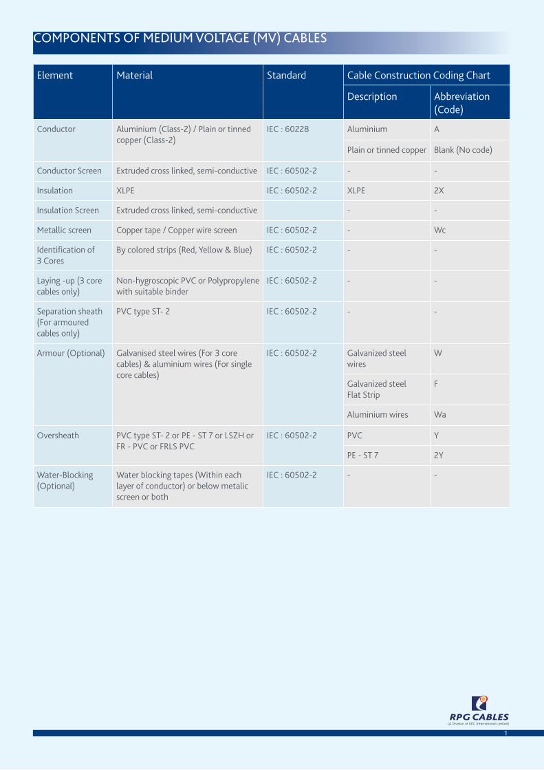
COMPONENTS OF MEDIUM VOLTAGE (MV) CABLES
Element Material Standard Cable Construction Coding Chart
Description Abbreviation (Code)
Conductor Aluminium (Class-2) / Plain or tinned copper (Class-2)
IEC : 60228 Aluminium A
Plain or tinned copper Blank (No code)
Conductor Screen Extruded cross linked, semi-conductive IEC : 60502-2 - -
Insulation XLPE IEC : 60502-2 XLPE 2X
Insulation Screen Extruded cross linked, semi-conductive - -
Metallic screen Copper tape / Copper wire screen IEC : 60502-2 - Wc
Identifi cation of 3 Cores
By colored strips (Red, Yellow & Blue) IEC : 60502-2 - -
Laying -up (3 core cables only)
Non-hygroscopic PVC or Polypropylene with suitable binder
IEC : 60502-2 - -
Separation sheath (For armoured cables only)
PVC type ST- 2 IEC : 60502-2 - -
Armour (Optional) Galvanised steel wires (For 3 core cables) & aluminium wires (For single core cables)
IEC : 60502-2 Galvanized steel wires
W
Galvanized steelFlat Strip
F
Aluminium wires Wa
Oversheath PVC type ST- 2 or PE - ST 7 or LSZH or FR - PVC or FRLS PVC
IEC : 60502-2 PVC Y
PE - ST 7 2Y
Water-Blocking (Optional)
Water blocking tapes (Within each layer of conductor) or below metalic screen or both
IEC : 60502-2 - -
1

RPG CABLES(A Division of KEC International Limited)
CROSS SECTIONAL DRAWINGS (FOR SINGLE / THREE CORE CABLES)
2
DRAWING NO.3 : 1 CORE ARMOURED -
A2XWaY(P) / 2XWaY(P)
1. Conductor 2. Inner Semicon 3. XLPE Insulation4. Outer Semicon 5. Copper Tape Screen6. Inner Sheathing 7. Aluminium Round Wire Armour8. PVC Sheathing
8 7
6
5
43
21
A2XWaA2XWaA2XW Y(P) / 2XWaY(P) / 2XWaY(P) / 2XW Y(P)
21
DRAWING 2 : 1 CORE COPPER WIRE
SCREENED , UNARMOURED - A2XWcY/2XWcY
1. Conductor 2. Inner Semicon 3. XLPE Insulation4. Outer Semicon 5. Copper Wire Screen6. Non - Semicon Tape 7. PVC Sheathing
7
6
5
43
21
DRAWING 2 : 1 CORE COPPER WIRE
SCREENED , UNARMOURED - A2XWcY/2XWcY
21
DRAWING NO.4 : 3 CORE ROUND WIRE
ARMOURED - A2XWY(P)/2XWY(P)
1. Conductor 2. Inner Semicon 3. XLPE insulation4. Outer Semicon 5. Copper Tape Screen6. Inner Sheathing 7. G.S Round Wire Armour8. PVC Sheathing
ARMOURED - A2XWY(P)/2XWY(P)
8 7
6
5
43
21
DRAWING 1 : 1 CORE UNARMOURED - A2XY/2XY
1. Conductor 2. Inner Semicon 3. XLPE Insulation4. Outer Semicon 5. Copper Tape Screen6. PVC Sheathing
DRAWING 1 : 1 CORE UNARMOURED - A2XY/2XY
6
5
43
21
DRAWING NO.5 : 3 CORE FLAT STRIP ARMOURED -
A2XFY(P)/2XFY(P)
1. Conductor 2. XLPE insulation3. Outer Semicon 4. Copper Tape Screen5. Inner Sheathing 6. G.S Flat Strip Armour7. PVC Sheathing
DRAWING NO.5 : 3 CORE FLAT STRIP ARMOURED -
A2XFY(P)/2XFY(P)
1
23
45
6
7RPG CABLES
(A Division of KEC International Limited)

RPG CABLES(A Division of KEC International Limited)
3
NOTE : Data for Water tight conductor , Steel/ Aluminium tape armour, Metal sheath, PE - ST 7 sheath can also be provided on customer specifi c request.
Nominal conductor
area (mm2)
Maximum Conductor
DC resistance at 20°C
(Ohm/km)
Cond. AC resistance at 50Hz & 90°C (Ohm/
km)
Inductive reactance at 50Hz and 90°C
Capacitance (μF/km)
Charging current
per phase(A/km)
Dielectric loss per phase
(W/km)
Fault current carrying
capacity for 1 second
Buried direct in the ground
In single-way ducts In
In air
Trefoil touching (Ohm/
km)
Flat touching (Ohm/
km)
Flat spaced (Ohm/
km)
Cond. (kA)
Copper Tape
Screen(kA)
Trefoil Flat spaced
Trefoil ducts
Flat touching
ducts
Trefoil Flat touching
Flat spaced
35 0.524 0.668 0.120 0.135 0.178 0.283 0.32 4.6 5.01 0.256 166 172 157 159 198 203 238
50 0.387 0.494 0.116 0.130 0.174 0.314 0.36 5.1 7.15 0.256 196 203 186 188 238 243 286
70 0.268 0.342 0.107 0.121 0.165 0.362 0.41 5.9 10.01 0.256 239 246 227 229 296 303 356
95 0.193 0.247 0.103 0.117 0.161 0.403 0.46 6.6 13.59 0.256 285 293 271 274 361 369 434
120 0.153 0.196 0.099 0.113 0.157 0.449 0.51 7.3 17.16 0.256 323 332 308 311 417 426 500
150 0.124 0.159 0.097 0.112 0.155 0.477 0.54 7.8 21.45 0.256 361 366 343 347 473 481 559
185 0.0991 0.128 0.093 0.107 0.151 0.533 0.60 8.7 26.46 0.256 406 410 387 391 543 550 637
240 0.0754 0.098 0.091 0.105 0.149 0.573 0.65 9.3 34.32 0.256 469 470 447 453 641 647 745
300 0.0601 0.079 0.090 0.104 0.148 0.580 0.66 9.4 42.90 0.256 526 524 504 510 735 739 846
400 0.0470 0.064 0.087 0.102 0.145 0.618 0.70 10.1 57.20 0.256 590 572 564 571 845 837 938
500 0.0366 0.051 0.085 0.100 0.143 0.659 0.75 10.7 71.50 0.256 640 635 608 603 942 944 1003
630 0.0283 0.042 0.083 0.098 0.141 0.735 0.83 12.0 90.09 0.256 712 703 676 668 1071 1070 1117
800 0.0221 0.036 0.081 0.096 0.139 0.830 0.94 13.5 114.40 0.256 781 770 742 732 1210 1207 1240
1000 0.0176 0.031 0.080 0.094 0.138 0.913 1.03 14.9 143.00 0.256 841 827 799 786 1332 1328 1344
eleCTriCal CharaCTerisTiCs CurrenT raTings
Nominal conductor
area (mm2)
Nominal conductor diameter
(mm)
Nominal insulation thickness
(mm)
Nominal diameter
over insulation
(mm)
Nominal thickness of Outer sheath (mm)
Nominal overall
diameter (mm)
Approx. mass
(Kg/m)
Max. pulling tension
(kN)
Min. bending radius Nominal duct diameter
During pulling (mm)
Set in position
(mm) (mm) (mm)
35 7.0 2.5 13.1 1.50 18.0 0.52 1.8 270 216 50 65
50 8.1 2.5 14.2 1.60 19.0 0.65 2.5 285 228 50 65
70 9.8 2.5 15.9 1.60 21.0 0.85 3.5 315 252 50 80
95 11.3 2.5 17.4 1.70 22.0 1.11 4.8 330 264 50 80
120 12.9 2.5 19.0 1.70 23.5 1.34 6.0 353 282 50 80
150 13.9 2.5 20.0 1.80 25.0 1.60 7.5 375 300 50 80
185 15.9 2.5 22.0 1.80 27.0 1.95 9.3 405 324 65 100
240 18.1 2.6 24.4 1.90 30.0 2.48 12.0 450 360 65 100
300 19.8 2.8 26.5 2.00 32.0 3.07 15.0 480 384 65 100
400 22.9 3.0 30.0 2.10 36.0 3.88 20.0 540 432 65 125
500 26.4 3.2 33.9 2.20 40.0 4.91 25.0 600 480 65 125
630 29.6 3.2 37.4 2.30 44.0 6.21 31.5 660 528 65 150
800 34.0 3.2 41.8 2.40 48.0 7.83 40.0 720 576 80 150
1000 37.8 3.2 45.6 2.60 52.0 9.62 50.0 780 624 80 190
3.6/6 (7.2) kv , single Core , Copper ConduCTor , Xlpe insulaTed , sCreened , unarmoured Cables (2Xy) as per ieC : 60502-2
RPG CABLES(A Division of KEC International Limited)
4
Nominal conductor
area (mm2)
Nominal conductor diameter
(mm)
Nominal insulation thickness
(mm)
Nominal diameter
over insulation
(mm)
Nominal thickness of Outer sheath (mm)
Nominal overall
diameter (mm)
Approx. mass
(Kg/m)
Max. pulling tension
(kN)
Min. bending radius Nominal duct diameter
During pulling (mm)
Set in position
(mm) (mm) (mm)
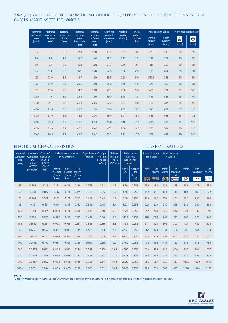
35 6.8 2.5 12.9 1.50 18.0 0.31 1.1 270 216 50 65
50 7.9 2.5 14.0 1.60 19.0 0.37 1.5 285 228 50 65
70 9.7 2.5 15.8 1.60 21.0 0.46 2.1 315 252 50 80
95 11.0 2.5 17.1 1.70 22.0 0.56 2.9 330 264 50 80
120 12.6 2.5 18.7 1.70 23.5 0.65 3.6 352.5 282 50 80
150 13.9 2.5 20.0 1.80 25.0 0.76 4.5 375 300 50 80
185 15.6 2.5 21.7 1.80 27.0 0.88 5.6 405 324 65 100
240 17.6 2.6 23.9 1.90 29.0 1.08 7.2 435 348 65 100
300 19.7 2.8 26.4 2.00 32.0 1.31 9.0 480 384 65 100
400 22.6 3.0 29.7 2.10 36.0 1.63 12.0 540 432 65 125
500 25.6 3.2 33.1 2.20 39.0 2.01 15.0 585 468 65 125
630 29.0 3.2 36.8 2.30 43.0 2.48 18.9 645 516 65 150
800 33.0 3.2 40.8 2.40 47.0 3.04 24.0 705 564 80 150
1000 36.8 3.2 44.6 2.60 51.0 3.71 30.0 765 612 80 190
NOTE : Data for Water tight conductor , Steel/ Aluminium tape armour, Metal sheath, PE - ST 7 sheath can also be provided on customer specifi c request.
Nominal conductor
area (mm2)
Maximum Conductor
DC resistance at 20°C
(Ohm/km)
Cond. AC resistance at 50Hz & 90°C (Ohm/
km)
Inductive reactance at 50Hz and 90°C
Capacitance (μF/km)
Charging current
per phase(A/km)
Dielectric loss per phase
(W/km)
Fault current carrying
capacity for 1 second
Buried direct in the ground
In single-way ducts In
In air
Trefoil touching (Ohm/
km)
Flat touching (Ohm/
km)
Flat spaced (Ohm/
km)
Cond. (kA)
Copper Tape
Screen(kA)
Trefoil Flat spaced
Trefoil ducts
Flat touching
ducts
Trefoil Flat touching
Flat spaced
35 0.868 1.113 0.121 0.136 0.180 0.278 0.31 4.5 3.29 0.256 129 134 122 123 154 157 185
50 0.641 0.822 0.117 0.131 0.175 0.309 0.35 5.0 4.70 0.256 152 157 144 146 184 189 222
70 0.443 0.568 0.107 0.121 0.165 0.359 0.41 5.9 6.58 0.256 186 192 176 178 230 236 278
95 0.32 0.411 0.104 0.118 0.162 0.396 0.45 6.4 8.93 0.256 221 229 210 213 280 287 338
120 0.253 0.325 0.099 0.114 0.158 0.441 0.50 7.2 11.28 0.256 252 260 240 242 324 332 391
150 0.206 0.265 0.097 0.112 0.155 0.477 0.54 7.8 14.10 0.256 281 288 267 271 368 376 440
185 0.1640 0.211 0.093 0.108 0.151 0.525 0.59 8.5 17.39 0.256 317 324 303 307 424 432 504
240 0.1250 0.162 0.091 0.106 0.149 0.561 0.63 9.1 22.56 0.256 367 373 351 356 502 511 593
300 0.1000 0.130 0.090 0.104 0.148 0.578 0.65 9.4 28.20 0.256 414 419 397 402 577 586 677
400 0.0778 0.102 0.087 0.102 0.145 0.611 0.69 9.9 37.60 0.256 470 466 451 457 673 676 769
500 0.0605 0.081 0.086 0.100 0.144 0.642 0.73 10.5 47.00 0.256 519 520 493 494 757 764 837
630 0.0469 0.064 0.084 0.098 0.142 0.722 0.82 11.8 59.22 0.256 586 584 557 555 876 882 950
800 0.0367 0.052 0.082 0.096 0.140 0.809 0.91 13.2 75.20 0.256 655 651 622 618 1005 1009 1070
1000 0.0291 0.044 0.080 0.095 0.138 0.891 1.01 14.5 94.00 0.256 723 715 687 679 1138 1140 1193
eleCTriCal CharaCTerisTiCs CurrenT raTings
3.6/6 (7.2) kv , single Core , aluminium ConduCTor , Xlpe insulaTed , sCreened , unarmoured Cables (a2Xy) as per ieC : 60502-2

RPG CABLES(A Division of KEC International Limited)
5
NOTE : Data for Water tight conductor , Steel/ Aluminium tape armour, Metal sheath, PE - ST 7 sheath can also be provided on customer specifi c request.
Nominal conductor
area (mm2)
Maximum Conductor
DC resistance at 20°C
(Ohm/km)
Cond. AC resistance at 50Hz & 90°C (Ohm/
km)
Inductive reactance at 50Hz and 90°C
Capacitance (μF/km)
Charging current
per phase(A/km)
Dielectric loss per phase
(W/km)
Fault current carrying
capacity for 1 second
Buried direct in the ground
In single-way ducts In
In air
Trefoil touching (Ohm/
km)
Flat touching (Ohm/
km)
Flat spaced (Ohm/
km)
Cond. (kA)
Copper Tape
Screen(kA)
Trefoil Flat spaced
Trefoil ducts
Flat touching
ducts
Trefoil Flat touching
Flat spaced
35 0.524 0.668 0.127 0.141 0.185 0.222 0.42 10.0 5.01 0.256 166 172 157 159 198 203 238
50 0.387 0.494 0.121 0.135 0.179 0.245 0.46 11.1 7.15 0.256 196 203 186 188 238 243 286
70 0.268 0.342 0.112 0.126 0.170 0.280 0.53 12.7 10.01 0.256 239 246 227 229 296 303 356
95 0.193 0.247 0.107 0.122 0.165 0.310 0.59 14.0 13.59 0.256 285 293 271 274 361 369 434
120 0.153 0.196 0.103 0.118 0.161 0.345 0.65 15.6 17.16 0.256 323 332 308 311 417 426 500
150 0.124 0.159 0.101 0.116 0.159 0.365 0.69 16.5 21.45 0.256 361 366 343 347 473 481 559
185 0.0991 0.128 0.097 0.111 0.155 0.407 0.77 18.4 26.46 0.256 406 410 387 391 543 550 637
240 0.0754 0.098 0.094 0.108 0.152 0.451 0.85 20.4 34.32 0.256 469 470 447 453 641 647 745
300 0.0601 0.079 0.092 0.106 0.150 0.487 0.92 22.0 42.90 0.256 526 524 504 510 735 739 846
400 0.0470 0.064 0.088 0.103 0.146 0.551 1.04 24.9 57.20 0.256 590 572 564 571 845 837 938
500 0.0366 0.051 0.085 0.100 0.143 0.622 1.17 28.2 71.50 0.256 640 635 608 603 942 944 1003
630 0.0283 0.042 0.084 0.098 0.142 0.693 1.31 31.4 90.09 0.256 712 703 676 668 1071 1070 1117
800 0.0221 0.035 0.082 0.096 0.140 0.783 1.48 35.4 114.40 0.256 781 770 742 732 1210 1207 1240
1000 0.0176 0.031 0.080 0.094 0.138 0.861 1.62 39.0 143.00 0.256 841 827 799 786 1332 1328 1344
eleCTriCal CharaCTerisTiCs CurrenT raTings
Nominal conductor
area (mm2)
Nominal conductor diameter
(mm)
Nominal insulation thickness
(mm)
Nominal diameter
over insulation
(mm)
Nominal thickness of Outer sheath (mm)
Nominal overall
diameter (mm)
Approx. mass
(Kg/m)
Max. pulling tension
(kN)
Min. bending radius Nominal duct diameter
During pulling (mm)
Set in position
(mm) (mm) (mm)
35 7.0 3.4 14.8 1.60 20.0 0.57 1.8 300 240 50 65
50 8.1 3.4 15.9 1.60 21.0 0.70 2.5 315 252 50 65
70 9.8 3.4 17.6 1.70 23.0 0.91 3.5 345 276 50 80
95 11.3 3.4 19.1 1.70 24.0 1.16 4.8 360 288 50 80
120 12.9 3.4 20.7 1.80 25.5 1.41 6.0 382.5 306 50 80
150 13.9 3.4 21.7 1.80 27.0 1.66 7.5 405 324 50 80
185 15.9 3.4 23.7 1.90 29.0 2.03 9.3 435 348 65 100
240 18.1 3.4 25.9 2.00 31.0 2.56 12.0 465 372 65 100
300 19.8 3.4 27.6 2.00 33.0 3.11 15.0 495 396 65 100
400 22.9 3.4 30.7 2.10 36.0 3.91 20.0 540 432 65 125
500 26.4 3.4 34.2 2.20 40.0 4.92 25.0 600 480 65 125
630 29.6 3.4 37.7 2.30 44.0 6.22 31.5 660 528 65 150
800 34.0 3.4 42.1 2.50 49.0 7.86 40.0 735 588 80 150
1000 37.8 3.4 45.9 2.60 53.0 9.63 50.0 795 636 80 190
6/10 (12) kv , single Core , Copper ConduCTor , Xlpe insulaTed , sCreened , unarmoured Cables (2Xy) as per ieC : 60502-2

RPG CABLES(A Division of KEC International Limited)
6
Nominal conductor
area (mm2)
Nominal conductor diameter
(mm)
Nominal insulation thickness
(mm)
Nominal diameter
over insulation
(mm)
Nominal thickness of Outer sheath (mm)
Nominal overall
diameter (mm)
Approx. mass
(Kg/m)
Max. pulling tension
(kN)
Min. bending radius Nominal duct diameter
During pulling (mm)
Set in position
(mm) (mm) (mm)
35 6.8 3.4 14.6 1.60 19.0 0.37 1.1 285 228 50 65
50 7.9 3.4 15.7 1.60 20.0 0.42 1.5 300 240 50 65
70 9.7 3.4 17.5 1.70 22.0 0.52 2.1 330 264 50 80
95 11.0 3.4 18.8 1.70 24.0 0.61 2.9 360 288 50 80
120 12.6 3.4 20.4 1.80 25.5 0.72 3.6 383 306 50 80
150 13.9 3.4 21.7 1.80 27.0 0.82 4.5 405 324 50 80
185 15.6 3.4 23.4 1.90 29.0 0.96 5.6 435 348 65 100
240 17.6 3.4 25.4 2.00 31.0 1.16 7.2 465 372 65 100
300 19.7 3.4 27.5 2.00 33.0 1.36 9.0 495 396 65 100
400 22.6 3.4 30.4 2.10 36.0 1.66 12.0 540 432 65 125
500 25.6 3.4 33.4 2.20 39.0 2.02 15.0 585 468 65 125
630 29.0 3.4 37.1 2.30 43.0 2.49 18.9 645 516 65 150
800 33.0 3.4 41.1 2.50 48.0 3.07 24.0 720 576 80 150
1000 36.8 3.4 44.9 2.60 52.0 3.72 30.0 780 624 80 190
NOTE : Data for Water tight conductor , Steel/ Aluminium tape armour, Metal sheath, PE - ST 7 sheath can also be provided on customer specifi c request.
Nominal conductor
area (mm2)
Maximum Conductor
DC resistance at 20°C
(Ohm/km)
Cond. AC resistance at 50Hz & 90°C (Ohm/
km)
Inductive reactance at 50Hz and 90°C
Capacitance (μF/km)
Charging current
per phase(A/km)
Dielectric loss per phase
(W/km)
Fault current carrying
capacity for 1 second
Buried direct in the ground
In single-way ducts In
In air
Trefoil touching (Ohm/
km)
Flat touching (Ohm/
km)
Flat spaced (Ohm/
km)
Cond. (kA)
Copper Tape
Screen(kA)
Trefoil Flat spaced
Trefoil ducts
Flat touching
ducts
Trefoil Flat touching
Flat spaced
35 0.868 1.113 0.128 0.142 0.186 0.217 0.41 9.8 3.29 0.256 129 134 122 123 154 157 185
50 0.641 0.822 0.122 0.136 0.180 0.240 0.45 10.9 4.70 0.256 152 157 144 146 184 189 222
70 0.443 0.568 0.112 0.127 0.170 0.278 0.52 12.6 6.58 0.256 186 192 176 178 230 236 278
95 0.32 0.411 0.108 0.123 0.166 0.305 0.58 13.8 8.93 0.256 221 229 210 213 280 287 338
120 0.253 0.325 0.104 0.119 0.162 0.338 0.64 15.3 11.28 0.256 252 260 240 242 324 332 391
150 0.206 0.265 0.101 0.116 0.159 0.365 0.69 16.5 14.10 0.256 281 288 267 271 368 376 440
185 0.1640 0.211 0.097 0.112 0.156 0.400 0.75 18.1 17.39 0.256 317 324 303 307 424 432 504
240 0.1250 0.162 0.095 0.109 0.153 0.442 0.83 20.0 22.56 0.256 367 373 351 356 502 511 593
300 0.1000 0.130 0.092 0.106 0.150 0.485 0.91 21.9 28.20 0.256 414 419 397 402 577 586 677
400 0.0778 0.102 0.088 0.103 0.146 0.544 1.03 24.6 37.60 0.256 470 466 451 457 673 676 769
500 0.0605 0.081 0.086 0.100 0.144 0.606 1.14 27.4 47.00 0.256 519 520 493 494 757 764 837
630 0.0469 0.064 0.084 0.099 0.142 0.681 1.28 30.8 59.22 0.256 586 584 557 555 876 882 950
800 0.0367 0.052 0.082 0.097 0.140 0.763 1.44 34.5 75.20 0.256 655 651 622 618 1005 1009 1070
1000 0.0291 0.044 0.080 0.095 0.138 0.841 1.58 38.0 94.00 0.256 723 715 687 679 1138 1140 1193
eleCTriCal CharaCTerisTiCs CurrenT raTings
6/10 (12) kv , single Core , aluminium ConduCTor , Xlpe insulaTed , sCreened , unarmoured Cables (a2Xy) as per ieC : 60502-2

RPG CABLES(A Division of KEC International Limited)
7
8.7/15 (17.5) kv , single Core , Copper ConduCTor , Xlpe insulaTed , sCreened , unarmoured Cables (2Xy) as per ieC : 60502-2
NOTE : Data for Water tight conductor , Steel/ Aluminium tape armour, Metal sheath, PE - ST 7 sheath can also be provided on customer specifi c request.
Nominal conductor
area (mm2)
Maximum Conductor
DC resistance at 20°C
(Ohm/km)
Cond. AC resistance at 50Hz & 90°C (Ohm/
km)
Inductive reactance at 50Hz and 90°C
Capacitance (μF/km)
Charging current
per phase(A/km)
Dielectric loss per phase
(W/km)
Fault current carrying
capacity for 1 second
Buried direct in the ground
In single-way ducts In
In air
Trefoil touching (Ohm/
km)
Flat touching (Ohm/
km)
Flat spaced (Ohm/
km)
Cond. (kA)
Copper Tape
Screen(kA)
Trefoil Flat spaced
Trefoil ducts
Flat touching
ducts
Trefoil Flat touching
Flat spaced
35 0.524 0.668 0.134 0.149 0.192 0.181 0.49 17.2 5.01 0.256 166 172 157 159 198 203 238
50 0.387 0.494 0.128 0.143 0.186 0.199 0.54 18.9 7.15 0.256 196 203 186 188 238 243 286
70 0.268 0.342 0.118 0.132 0.176 0.226 0.62 21.5 10.01 0.256 239 246 227 229 296 303 356
95 0.193 0.247 0.113 0.128 0.171 0.249 0.68 23.7 13.59 0.256 285 293 271 274 361 369 434
120 0.153 0.196 0.109 0.124 0.167 0.275 0.75 26.2 17.16 0.256 323 332 308 311 417 426 500
150 0.124 0.159 0.107 0.121 0.165 0.291 0.79 27.7 21.45 0.256 361 366 343 347 473 481 559
185 0.0991 0.128 0.102 0.117 0.160 0.322 0.88 30.6 26.46 0.256 406 410 387 391 543 550 637
240 0.0754 0.098 0.098 0.113 0.156 0.356 0.97 33.8 34.32 0.256 469 470 447 453 641 647 745
300 0.0601 0.079 0.096 0.111 0.154 0.383 1.05 36.4 42.90 0.256 526 524 504 510 735 739 846
400 0.0470 0.063 0.092 0.107 0.150 0.431 1.18 41.0 57.20 0.256 590 572 564 571 845 837 938
500 0.0366 0.051 0.089 0.104 0.147 0.486 1.33 46.2 71.50 0.256 640 635 608 603 942 944 1003
630 0.0283 0.042 0.087 0.102 0.145 0.539 1.47 51.3 90.09 0.256 712 703 676 668 1071 1070 1117
800 0.0221 0.035 0.084 0.099 0.142 0.608 1.66 57.8 114.40 0.256 781 770 742 732 1210 1207 1240
1000 0.0176 0.030 0.083 0.097 0.141 0.667 1.82 63.4 143.00 0.256 841 827 799 786 1332 1328 1344
eleCTriCal CharaCTerisTiCs CurrenT raTings
Nominal conductor
area (mm2)
Nominal conductor diameter
(mm)
Nominal insulation thickness
(mm)
Nominal diameter
over insulation
(mm)
Nominal thickness of Outer sheath (mm)
Nominal overall
diameter (mm)
Approx. mass
(Kg/m)
Max. pulling tension
(kN)
Min. bending radius Nominal duct diameter
During pulling (mm)
Set in position
(mm) (mm) (mm)
35 7.0 4.5 17.0 1.70 22.0 0.65 1.8 440 264 50 65
50 8.1 4.5 18.1 1.70 23.0 0.78 2.5 460 276 50 65
70 9.8 4.5 19.8 1.70 25.0 0.99 3.5 500 300 50 80
95 11.3 4.5 21.3 1.80 26.0 1.26 4.8 520 312 50 80
120 12.9 4.5 22.9 1.90 27.5 1.52 6.0 550 330 50 80
150 13.9 4.5 23.9 1.90 29.0 1.77 7.5 580 348 50 80
185 15.9 4.5 25.9 2.00 31.0 2.14 9.3 620 372 65 100
240 18.1 4.5 28.1 2.00 34.0 2.67 12.0 680 408 65 100
300 19.8 4.5 29.8 2.10 36.0 3.24 15.0 720 432 65 100
400 22.9 4.5 32.9 2.20 39.0 4.05 20.0 780 468 65 125
500 26.4 4.5 36.4 2.30 43.0 5.07 25.0 860 516 65 125
630 29.6 4.5 39.9 2.40 46.0 6.39 31.5 920 552 65 150
800 34.0 4.5 44.3 2.50 51.0 8.03 40.0 1020 612 80 150
1000 37.8 4.5 48.1 2.70 55.0 9.83 50.0 1100 660 80 190

RPG CABLES(A Division of KEC International Limited)
8
8.7/15 (17.5) kv , single Core , aluminium ConduCTor , Xlpe insulaTed , sCreened , unarmoured Cables (a2Xy) as per ieC : 60502-2
Nominal conductor
area (mm2)
Nominal conductor diameter
(mm)
Nominal insulation thickness
(mm)
Nominal diameter
over insulation
(mm)
Nominal thickness of Outer sheath (mm)
Nominal overall
diameter (mm)
Approx. mass
(Kg/m)
Max. pulling tension
(kN)
Min. bending radius Nominal duct diameter
During pulling (mm)
Set in position
(mm) (mm) (mm)
35 6.8 4.5 16.8 1.70 22.0 0.45 1.1 440 264 50 65
50 7.9 4.5 17.9 1.70 23.0 0.51 1.5 460 276 50 65
70 9.7 4.5 19.7 1.70 25.0 0.60 2.1 500 300 50 80
95 11.0 4.5 21.0 1.80 26.0 0.71 2.9 520 312 50 80
120 12.6 4.5 22.6 1.90 27.5 0.83 3.6 550 330 50 80
150 13.9 4.5 23.9 1.90 29.0 0.93 4.5 580 348 50 80
185 15.6 4.5 25.6 2.00 31.0 1.08 5.6 620 372 65 100
240 17.6 4.5 27.6 2.00 33.0 1.27 7.2 660 396 65 100
300 19.7 4.5 29.7 2.10 35.0 1.49 9.0 700 420 65 100
400 22.6 4.5 32.6 2.20 39.0 1.80 12.0 780 468 65 125
500 25.6 4.5 35.6 2.30 42.0 2.18 15.0 840 504 65 125
630 29.0 4.5 39.3 2.40 46.0 2.65 18.9 920 552 65 150
800 33.0 4.5 43.3 2.50 50.0 3.24 24.0 1000 600 80 150
1000 36.8 4.5 47.1 2.70 54.0 3.92 30.0 1080 648 80 190
NOTE : Data for Water tight conductor , Steel/ Aluminium tape armour, Metal sheath, PE - ST 7 sheath can also be provided on customer specifi c request.
Nominal conductor
area (mm2)
Maximum Conductor
DC resistance at 20°C
(Ohm/km)
Cond. AC resistance at 50Hz & 90°C (Ohm/
km)
Inductive reactance at 50Hz and 90°C
Capacitance (μF/km)
Charging current
per phase(A/km)
Dielectric loss per phase
(W/km)
Fault current carrying
capacity for 1 second
Buried direct in the ground
In single-way ducts In
In air
Trefoil touching (Ohm/
km)
Flat touching (Ohm/
km)
Flat spaced (Ohm/
km)
Cond. (kA)
Copper Tape
Screen(kA)
Trefoil Flat spaced
Trefoil ducts
Flat touching
ducts
Trefoil Flat touching
Flat spaced
35 0.868 1.113 0.135 0.150 0.193 0.178 0.49 16.9 3.29 0.256 129 134 122 123 154 157 185
50 0.641 0.822 0.129 0.144 0.187 0.196 0.53 18.6 4.70 0.256 152 157 144 146 184 189 222
70 0.443 0.568 0.118 0.133 0.176 0.224 0.61 21.3 6.58 0.256 186 192 176 178 230 236 278
95 0.32 0.411 0.114 0.129 0.172 0.245 0.67 23.3 8.93 0.256 221 229 210 213 280 287 338
120 0.253 0.325 0.110 0.124 0.168 0.270 0.74 25.7 11.28 0.256 252 260 240 242 324 332 391
150 0.206 0.265 0.107 0.121 0.165 0.291 0.79 27.7 14.10 0.256 281 288 267 271 368 376 440
185 0.1640 0.211 0.103 0.117 0.161 0.317 0.87 30.2 17.39 0.256 317 324 303 307 424 432 504
240 0.1250 0.161 0.099 0.114 0.157 0.349 0.95 33.2 22.56 0.256 367 373 351 356 502 511 593
300 0.1000 0.130 0.096 0.111 0.154 0.382 1.04 36.3 28.20 0.256 414 419 397 402 577 586 677
400 0.0778 0.102 0.092 0.107 0.151 0.427 1.17 40.6 37.60 0.256 470 466 451 457 673 676 769
500 0.0605 0.080 0.090 0.104 0.148 0.473 1.29 45.0 47.00 0.256 519 520 493 494 757 764 837
630 0.0469 0.064 0.088 0.102 0.146 0.530 1.45 50.4 59.22 0.256 586 584 557 555 876 882 950
800 0.0367 0.052 0.085 0.100 0.143 0.592 1.62 56.3 75.20 0.256 655 651 622 618 1005 1009 1070
1000 0.0291 0.043 0.083 0.098 0.141 0.651 1.78 61.9 94.00 0.256 723 715 687 679 1138 1140 1193
eleCTriCal CharaCTerisTiCs CurrenT raTings

RPG CABLES(A Division of KEC International Limited)
9
12/20(24) kv , single Core , Copper ConduCTor , Xlpe insulaTed , sCreened , unarmoured Cables (2Xy) as per ieC : 60502-2
NOTE : Data for Water tight conductor , Steel/ Aluminium tape armour, Metal sheath, PE - ST 7 sheath can also be provided on customer specifi c request.
Nominal conductor
area (mm2)
Maximum Conductor
DC resistance at 20°C
(Ohm/km)
Cond. AC resistance at 50Hz & 90°C (Ohm/
km)
Inductive reactance at 50Hz and 90°C
Capacitance (μF/km)
Charging current
per phase(A/km)
Dielectric loss per phase
(W/km)
Fault current carrying
capacity for 1 second
Buried direct in the ground
In single-way ducts In
In air
Trefoil touching (Ohm/
km)
Flat touching (Ohm/
km)
Flat spaced (Ohm/
km)
Cond. (kA)
Copper Tape
Screen(kA)
Trefoil Flat spaced
Trefoil ducts
Flat touching
ducts
Trefoil Flat touching
Flat spaced
35 0.524 0.668 0.140 0.154 0.198 0.158 0.60 28.6 5.01 0.256 166 172 157 159 198 203 238
50 0.387 0.494 0.134 0.148 0.192 0.173 0.65 31.2 7.15 0.256 196 203 186 188 238 243 286
70 0.268 0.342 0.123 0.138 0.181 0.195 0.74 35.3 10.01 0.256 239 246 227 229 296 303 356
95 0.193 0.247 0.119 0.133 0.177 0.214 0.81 38.7 13.59 0.256 285 293 271 274 361 369 434
120 0.153 0.196 0.113 0.128 0.172 0.236 0.89 42.6 17.16 0.256 323 332 308 311 417 426 500
150 0.124 0.159 0.111 0.126 0.169 0.249 0.94 45.0 21.45 0.256 361 366 343 347 473 481 559
185 0.0991 0.128 0.106 0.120 0.164 0.274 1.03 49.7 26.46 0.256 406 410 387 391 543 550 637
240 0.0754 0.098 0.102 0.117 0.160 0.302 1.14 54.7 34.32 0.256 469 470 447 453 641 647 745
300 0.0601 0.079 0.100 0.114 0.158 0.325 1.22 58.7 42.90 0.256 526 524 504 510 735 739 846
400 0.0470 0.063 0.096 0.110 0.154 0.364 1.37 65.9 57.20 0.256 590 572 564 571 845 837 938
500 0.0366 0.051 0.092 0.107 0.150 0.409 1.54 74.0 71.50 0.256 640 635 608 603 942 944 1003
630 0.0283 0.041 0.090 0.105 0.148 0.453 1.71 82.0 90.09 0.256 712 703 676 668 1071 1070 1117
800 0.0221 0.035 0.087 0.102 0.145 0.509 1.92 92.1 114.40 0.256 781 770 742 732 1210 1207 1240
1000 0.0176 0.030 0.085 0.100 0.143 0.557 2.10 100.8 143.00 0.256 841 827 799 786 1332 1328 1344
eleCTriCal CharaCTerisTiCs CurrenT raTings
Nominal conductor
area (mm2)
Nominal conductor diameter
(mm)
Nominal insulation thickness
(mm)
Nominal diameter
over insulation
(mm)
Nominal thickness of Outer sheath (mm)
Nominal overall
diameter (mm)
Approx. mass
(Kg/m)
Max. pulling tension
(kN)
Min. bending radius Nominal duct diameter
During pulling (mm)
Set in position
(mm) (mm) (mm)
35 7.0 5.5 19.0 1.70 24.0 0.72 1.8 480 288 50 65
50 8.1 5.5 20.1 1.80 25.0 0.87 2.5 500 300 50 65
70 9.8 5.5 21.8 1.80 27.0 1.09 3.5 540 324 50 80
95 11.3 5.5 23.3 1.90 29.0 1.36 4.8 580 348 50 80
120 12.9 5.5 24.9 1.90 29.5 1.61 6.0 590 354 50 80
150 13.9 5.5 25.9 2.00 31.0 1.88 7.5 620 372 50 80
185 15.9 5.5 27.9 2.00 33.0 2.24 9.3 660 396 65 100
240 18.1 5.5 30.1 2.10 36.0 2.79 12.0 720 432 65 100
300 19.8 5.5 31.8 2.20 38.0 3.37 15.0 760 456 65 100
400 22.9 5.5 34.9 2.30 41.0 4.19 20.0 820 492 65 125
500 26.4 5.5 38.4 2.40 45.0 5.23 25.0 900 540 65 125
630 29.6 5.5 41.9 2.50 48.0 6.56 31.5 960 576 65 150
800 34.0 5.5 46.3 2.60 53.0 8.21 40.0 1060 636 80 150
1000 37.8 5.5 50.1 2.70 57.0 10.00 50.0 1140 684 80 190

RPG CABLES(A Division of KEC International Limited)
10
12/20(24) kv , single Core , aluminium ConduCTor , Xlpe insulaTed , sCreened , unarmoured Cables (a2Xy) as per ieC : 60502-2
Nominal conductor
area (mm2)
Nominal conductor diameter
(mm)
Nominal insulation thickness
(mm)
Nominal diameter
over insulation
(mm)
Nominal thickness of Outer sheath (mm)
Nominal overall
diameter (mm)
Approx. mass
(Kg/m)
Max. pulling tension
(kN)
Min. bending radius Nominal duct diameter
During pulling (mm)
Set in position
(mm) (mm) (mm)
35 6.8 5.5 18.8 1.70 24.0 0.52 1.1 480 288 50 65
50 7.9 5.5 19.9 1.80 25.0 0.59 1.5 500 300 50 65
70 9.7 5.5 21.7 1.80 27.0 0.69 2.1 540 324 50 80
95 11.0 5.5 23.0 1.90 28.0 0.81 2.9 560 336 50 80
120 12.6 5.5 24.6 1.90 29.5 0.91 3.6 590 354 50 80
150 13.9 5.5 25.9 2.00 31.0 1.03 4.5 620 372 50 80
185 15.6 5.5 27.6 2.00 33.0 1.17 5.6 660 396 65 100
240 17.6 5.5 29.6 2.10 35.0 1.39 7.2 700 420 65 100
300 19.7 5.5 31.7 2.20 38.0 1.61 9.0 760 456 65 100
400 22.6 5.5 34.6 2.30 41.0 1.94 12.0 820 492 65 125
500 25.6 5.5 37.6 2.40 44.0 2.33 15.0 880 528 65 125
630 29.0 5.5 41.3 2.50 48.0 2.82 18.9 960 576 65 150
800 33.0 5.5 45.3 2.60 52.0 3.41 24.0 1040 624 80 150
1000 36.8 5.5 49.1 2.70 56.0 4.09 30.0 1120 672 80 190
NOTE : Data for Water tight conductor , Steel/ Aluminium tape armour, Metal sheath, PE - ST 7 sheath can also be provided on customer specifi c request.
Nominal conductor
area (mm2)
Maximum Conductor
DC resistance at 20°C
(Ohm/km)
Cond. AC resistance at 50Hz & 90°C (Ohm/
km)
Inductive reactance at 50Hz and 90°C
Capacitance (μF/km)
Charging current
per phase(A/km)
Dielectric loss per phase
(W/km)
Fault current carrying
capacity for 1 second
Buried direct in the ground
In single-way ducts In
In air
Trefoil touching (Ohm/
km)
Flat touching (Ohm/
km)
Flat spaced (Ohm/
km)
Cond. (kA)
Copper Tape
Screen(kA)
Trefoil Flat spaced
Trefoil ducts
Flat touching
ducts
Trefoil Flat touching
Flat spaced
35 0.868 1.113 0.141 0.155 0.199 0.155 0.59 28.1 3.29 0.256 129 134 122 123 154 157 185
50 0.641 0.822 0.135 0.150 0.193 0.170 0.64 30.8 4.70 0.256 152 157 144 146 184 189 222
70 0.443 0.568 0.124 0.138 0.182 0.194 0.73 35.1 6.58 0.256 186 192 176 178 230 236 278
95 0.32 0.411 0.119 0.134 0.177 0.211 0.79 38.2 8.93 0.256 221 229 210 213 280 287 338
120 0.253 0.325 0.114 0.129 0.172 0.232 0.87 41.9 11.28 0.256 252 260 240 242 324 332 391
150 0.206 0.265 0.111 0.126 0.169 0.249 0.94 45.0 14.10 0.256 281 288 267 271 368 376 440
185 0.1640 0.211 0.107 0.121 0.165 0.271 1.02 49.0 17.39 0.256 317 324 303 307 424 432 504
240 0.1250 0.161 0.103 0.118 0.161 0.296 1.12 53.6 22.56 0.256 367 373 351 356 502 511 593
300 0.1000 0.130 0.100 0.115 0.158 0.323 1.22 58.5 28.20 0.256 414 419 397 402 577 586 677
400 0.0778 0.102 0.096 0.111 0.154 0.360 1.36 65.2 37.60 0.256 470 466 451 457 673 676 769
500 0.0605 0.080 0.093 0.108 0.151 0.399 1.50 72.2 47.00 0.256 519 520 493 494 757 764 837
630 0.0469 0.064 0.091 0.105 0.149 0.445 1.68 80.6 59.22 0.256 586 584 557 555 876 882 950
800 0.0367 0.052 0.088 0.102 0.146 0.496 1.87 89.8 75.20 0.256 655 651 622 618 1005 1009 1070
1000 0.0291 0.043 0.086 0.100 0.144 0.544 2.05 98.5 94.00 0.256 723 715 687 679 1138 1140 1193
eleCTriCal CharaCTerisTiCs CurrenT raTings

RPG CABLES(A Division of KEC International Limited)
11
18/30(36) kv , single Core , Copper ConduCTor , Xlpe insulaTed , sCreened , unarmoured Cables (2Xy) as per ieC : 60502-2
NOTE : Data for Water tight conductor , Steel/ Aluminium tape armour, Metal sheath, PE - ST 7 sheath can also be provided on customer specifi c request.
Nominal conductor
area (mm2)
Maximum Conductor
DC resistance at 20°C
(Ohm/km)
Cond. AC resistance at 50Hz & 90°C (Ohm/
km)
Inductive reactance at 50Hz and 90°C
Capacitance (μF/km)
Charging current
per phase(A/km)
Dielectric loss per phase
(W/km)
Fault current carrying
capacity for 1 second
Buried direct in the ground
In single-way ducts In
In air
Trefoil touching (Ohm/
km)
Flat touching (Ohm/
km)
Flat spaced (Ohm/
km)
Cond. (kA)
Copper Tape
Screen(kA)
Trefoil Flat spaced
Trefoil ducts
Flat touching
ducts
Trefoil Flat touching
Flat spaced
50 0.387 0.494 0.146 0.161 0.204 0.136 0.77 55.4 7.15 0.256 196 203 186 188 238 243 286
70 0.268 0.342 0.135 0.150 0.194 0.152 0.86 61.8 10.01 0.256 239 246 227 229 296 303 356
95 0.193 0.247 0.130 0.144 0.188 0.165 0.93 67.3 13.59 0.256 285 293 271 274 361 369 434
120 0.153 0.196 0.124 0.139 0.182 0.180 1.02 73.5 17.16 0.256 323 332 308 311 417 426 500
150 0.124 0.159 0.121 0.136 0.179 0.190 1.07 77.2 21.45 0.256 361 366 343 347 473 481 559
185 0.0991 0.127 0.116 0.130 0.174 0.208 1.17 84.5 26.46 0.256 406 410 387 391 543 550 637
240 0.0754 0.098 0.112 0.126 0.170 0.227 1.28 92.4 34.32 0.256 469 470 447 453 641 647 745
300 0.0601 0.079 0.108 0.123 0.166 0.243 1.37 98.8 42.90 0.256 526 524 504 510 735 739 846
400 0.0470 0.063 0.104 0.118 0.162 0.270 1.53 110.0 57.20 0.256 590 572 564 571 845 837 938
500 0.0366 0.050 0.099 0.114 0.158 0.301 1.70 122.6 71.50 0.256 640 635 608 603 942 944 1003
630 0.0283 0.041 0.097 0.111 0.155 0.332 1.87 135.0 90.09 0.256 712 703 676 668 1071 1070 1117
800 0.0221 0.034 0.093 0.108 0.152 0.370 2.09 150.7 114.40 0.256 781 770 742 732 1210 1207 1240
1000 0.0176 0.029 0.091 0.105 0.149 0.404 2.28 164.3 143.00 0.256 841 827 799 786 1332 1328 1344
eleCTriCal CharaCTerisTiCs CurrenT raTings
Nominal conductor
area (mm2)
Nominal conductor diameter
(mm)
Nominal insulation thickness
(mm)
Nominal diameter
over insulation
(mm)
Nominal thickness of Outer sheath (mm)
Nominal overall
diameter (mm)
Approx. mass
(Kg/m)
Max. pulling tension
(kN)
Min. bending radius Nominal duct diameter
During pulling (mm)
Set in position
(mm) (mm) (mm)
50 8.1 8.0 25.2 1.90 31.0 1.10 2.5 620 372 50 65
70 9.8 8.0 26.9 2.00 33.0 1.35 3.5 660 396 50 80
95 11.3 8.0 28.4 2.10 34.0 1.64 4.8 680 408 50 80
120 12.9 8.0 30.0 2.10 35.5 1.90 6.0 710 426 50 80
150 13.9 8.0 31.0 2.10 37.0 2.16 7.5 740 444 50 80
185 15.9 8.0 33.0 2.20 39.0 2.56 9.3 780 468 65 100
240 18.1 8.0 35.2 2.30 41.0 3.13 12.0 820 492 65 100
300 19.8 8.0 36.9 2.30 43.0 3.71 15.0 860 516 65 100
400 22.9 8.0 40.0 2.50 47.0 4.58 20.0 940 564 65 125
500 26.4 8.0 43.5 2.50 50.0 5.62 25.0 1000 600 65 125
630 29.6 8.0 47.0 2.70 54.0 7.01 31.5 1080 648 65 150
800 34.0 8.0 51.4 2.80 59.0 8.70 40.0 1180 708 80 150
1000 37.8 8.0 55.2 2.90 63.0 10.52 50.0 1260 756 80 190

RPG CABLES(A Division of KEC International Limited)
12
18/30(36) kv , single Core , aluminium ConduCTor , Xlpe insulaTed , sCreened , unarmoured Cables (2Xy) as per ieC : 60502-2
Nominal conductor
area (mm2)
Nominal conductor diameter
(mm)
Nominal insulation thickness
(mm)
Nominal diameter
over insulation
(mm)
Nominal thickness of Outer sheath (mm)
Nominal overall
diameter (mm)
Approx. mass
(Kg/m)
Max. pulling tension
(kN)
Min. bending radius Nominal duct diameter
During pulling (mm)
Set in position
(mm) (mm) (mm)
50 7.9 8.0 25.0 1.90 30.0 0.83 1.5 600 360 50 65
70 9.7 8.0 26.8 2.00 32.0 0.96 2.1 640 384 50 80
95 11.0 8.0 28.1 2.10 34.0 1.08 2.9 680 408 50 80
120 12.6 8.0 29.7 2.10 35.5 1.20 3.6 710 426 50 80
150 13.9 8.0 31.0 2.10 37.0 1.32 4.5 740 444 50 80
185 15.6 8.0 32.7 2.20 39.0 1.49 5.6 780 468 65 100
240 17.6 8.0 34.7 2.30 41.0 1.72 7.2 820 492 65 100
300 19.7 8.0 36.8 2.30 43.0 1.95 9.0 860 516 65 100
400 22.6 8.0 39.7 2.50 46.0 2.33 12.0 920 552 65 125
500 25.6 8.0 42.7 2.50 49.0 2.72 15.0 980 588 65 125
630 29.0 8.0 46.4 2.70 53.0 3.26 18.9 1060 636 65 150
800 33.0 8.0 50.4 2.80 58.0 3.89 24.0 1160 696 80 150
1000 36.8 8.0 54.2 2.90 62.0 4.60 30.0 1240 744 80 190
NOTE : Data for Water tight conductor , Steel/ Aluminium tape armour, Metal sheath, PE - ST 7 sheath can also be provided on customer specifi c request.
Nominal conductor
area (mm2)
Maximum Conductor
DC resistance at 20°C
(Ohm/km)
Cond. AC resistance at 50Hz & 90°C (Ohm/
km)
Inductive reactance at 50Hz and 90°C
Capacitance (μF/km)
Charging current
per phase(A/km)
Dielectric loss per phase
(W/km)
Fault current carrying
capacity for 1 second
Buried direct in the ground
In single-way ducts In
In air
Trefoil touching (Ohm/
km)
Flat touching (Ohm/
km)
Flat spaced (Ohm/
km)
Cond. (kA)
Copper Tape
Screen(kA)
Trefoil Flat spaced
Trefoil ducts
Flat touching
ducts
Trefoil Flat touching
Flat spaced
50 0.641 0.822 0.147 0.162 0.206 0.134 0.76 54.6 4.70 0.256 152 157 144 146 184 189 222
70 0.443 0.568 0.136 0.150 0.194 0.151 0.85 61.5 6.58 0.256 186 192 176 178 230 236 278
95 0.32 0.411 0.131 0.145 0.189 0.163 0.92 66.4 8.93 0.256 221 229 210 213 280 287 338
120 0.253 0.325 0.125 0.140 0.183 0.178 1.00 72.3 11.28 0.256 252 260 240 242 324 332 391
150 0.206 0.265 0.121 0.136 0.179 0.190 1.07 77.2 14.10 0.256 281 288 267 271 368 376 440
185 0.1640 0.211 0.117 0.131 0.175 0.205 1.16 83.4 17.39 0.256 317 324 303 307 424 432 504
240 0.1250 0.161 0.112 0.127 0.171 0.223 1.26 90.7 22.56 0.256 367 373 351 356 502 511 593
300 0.1000 0.129 0.109 0.123 0.167 0.242 1.37 98.4 28.20 0.256 414 419 397 402 577 586 677
400 0.0778 0.101 0.104 0.119 0.162 0.267 1.51 108.9 37.60 0.256 470 466 451 457 673 676 769
500 0.0605 0.080 0.100 0.115 0.158 0.294 1.66 119.7 47.00 0.256 519 520 493 494 757 764 837
630 0.0469 0.063 0.098 0.112 0.156 0.326 1.84 132.8 59.22 0.256 586 584 557 555 876 882 950
800 0.0367 0.051 0.094 0.109 0.152 0.361 2.04 147.2 75.20 0.256 655 651 622 618 1005 1009 1070
1000 0.0291 0.042 0.092 0.106 0.150 0.395 2.23 160.7 94.00 0.256 723 715 687 679 1138 1140 1193
eleCTriCal CharaCTerisTiCs CurrenT raTings

RPG CABLES(A Division of KEC International Limited)
13
Nominal conductor
area (mm2)
Nominal conductor diameter
(mm)
Nominal insulation thickness
(mm)
Nominal diameter
over insulation
(mm)
Nominal screen area
(mm2)
Nominal diameter over wire
screen (mm)
Minimum thickness of Over sheath
(mm)
Nominal overall
diameter (mm)
Approx. mass (Kg/m)
Max. pulling tension
(kN)
Min. bending radius Nominal duct diameter
During pulling (mm)
Set in position
(mm) (mm) (mm)
35 7.0 2.5 13.1 16.0 15.7 1.08 20.0 0.69 1.8 300 240 50 65
50 8.1 2.5 14.2 16.0 16.8 1.08 21.0 0.81 2.5 315 252 50 65
70 9.8 2.5 15.9 16.0 18.5 1.08 23.0 1.01 3.5 345 276 50 80
95 11.3 2.5 17.4 16.0 19.9 1.16 24.0 1.26 4.8 360 288 50 80
120 12.9 2.5 19.0 16.0 21.6 1.24 25.5 1.51 6.0 383 306 50 80
150 13.9 2.5 20.0 25.0 22.6 1.24 27.0 1.84 7.5 405 324 50 80
185 15.9 2.5 22.0 25.0 24.6 1.32 29.0 2.20 9.3 435 348 65 100
240 18.1 2.6 24.4 25.0 26.9 1.32 32.0 2.72 12.0 480 384 65 100
300 19.8 2.8 26.5 25.0 29.1 1.40 34.0 3.30 15.0 510 408 65 100
400 22.9 3.0 30.0 35.0 32.6 1.56 38.0 4.22 20.0 570 456 65 125
500 26.4 3.2 33.9 35.0 36.5 1.64 42.0 5.25 25.0 630 504 65 125
630 29.6 3.2 37.4 35.0 39.9 1.72 46.0 6.55 31.5 690 552 65 150
800 34.0 3.2 41.8 35.0 44.3 1.80 50.0 8.17 40.0 750 600 80 150
1000 37.8 3.2 45.6 35.0 48.1 1.88 54.0 9.93 50.0 810 648 80 190
3.6/6 (7.2) kv , single Core , Copper ConduCTor , Xlpe insulaTed , Copper Wire sCreened , unarmoured Cables (2XWcy) as per ieC : 60502-2
Nominal conductor
area (mm2)
Maximum Conductor
DC resistance at 20°C
(Ohm/km)
Cond. AC resistance at 50Hz & 90°C (Ohm/
km)
Inductive reactance at 50Hz and 90°C
Capacitance (μF/km)
Charging current
per phase(A/km)
Dielectric loss per phase
(W/km)
Fault current carrying
capacity for 1 second
Buried direct in the ground
In single-way ducts In
In air
Trefoil touching (Ohm/
km)
Flat touching (Ohm/
km)
Flat spaced (Ohm/
km)
Cond. (kA)
Screen (kA)
Trefoil Flat spaced
Trefoil ducts
Flat touching
ducts
Trefoil Flat touching
Flat spaced
35 0.524 0.668 0.128 0.142 0.186 0.283 0.34 5.1 5.01 2.29 166 172 157 159 198 203 238
50 0.387 0.494 0.122 0.137 0.180 0.314 0.38 5.7 7.15 2.29 196 203 186 188 238 243 286
70 0.268 0.342 0.112 0.127 0.170 0.362 0.43 6.6 10.01 2.29 239 246 227 229 296 303 356
95 0.193 0.247 0.108 0.123 0.166 0.403 0.48 7.3 13.59 2.29 285 293 271 274 361 369 434
120 0.153 0.196 0.104 0.119 0.162 0.449 0.54 8.2 17.16 2.29 323 332 308 311 417 426 500
150 0.124 0.159 0.102 0.117 0.160 0.477 0.57 8.7 21.45 3.58 361 366 343 347 473 481 559
185 0.0991 0.128 0.098 0.112 0.156 0.533 0.64 9.7 26.46 3.58 406 410 387 391 543 550 637
240 0.0754 0.098 0.095 0.109 0.153 0.573 0.68 10.4 34.32 3.58 469 470 447 453 641 647 745
300 0.0601 0.079 0.093 0.108 0.151 0.580 0.69 10.5 42.90 3.58 526 524 504 510 735 739 846
400 0.0470 0.063 0.091 0.105 0.149 0.618 0.74 11.2 57.20 5.01 590 572 564 571 845 837 938
500 0.0366 0.051 0.088 0.103 0.146 0.659 0.79 12.0 71.50 5.01 640 635 608 603 942 944 1003
630 0.0283 0.042 0.086 0.101 0.145 0.735 0.88 13.3 90.09 5.01 712 703 676 668 1071 1070 1117
800 0.0221 0.035 0.084 0.098 0.142 0.830 0.99 15.1 114.40 5.01 781 770 742 732 1210 1207 1240
1000 0.0176 0.030 0.082 0.097 0.140 0.913 1.09 16.6 143.00 5.01 841 827 799 786 1332 1328 1344
eleCTriCal CharaCTerisTiCs CurrenT raTings
NOTE :Data for Water tight conductor , Steel/ Aluminium tape armour, Metal sheath, PE - ST 7 sheath can also be provided on customer specifi c request.

RPG CABLES(A Division of KEC International Limited)
14
Nominal conductor
area (mm2)
Nominal conductor diameter
(mm)
Nominal insulation thickness
(mm)
Nominal diameter
over insulation
(mm)
Nominal screen area
(mm2)
Nominal diameter over wire
screen (mm)
Minimum thickness of Over sheath
(mm)
Nominal overall
diameter (mm)
Approx. mass (Kg/m)
Max. pulling tension
(kN)
Min. bending radius Nominal duct diameter
During pulling (mm)
Set in position
(mm) (mm) (mm)
35 6.8 2.5 12.9 16.0 15.5 1.08 20.0 0.48 1.1 300 240 50 65
50 7.9 2.5 14.0 16.0 16.6 1.08 21.0 0.53 1.5 315 252 50 65
70 9.7 2.5 15.8 16.0 18.4 1.08 23.0 0.62 2.1 345 276 50 80
95 11.0 2.5 17.1 16.0 19.7 1.16 24.0 0.72 2.9 360 288 50 80
120 12.6 2.5 18.7 16.0 21.3 1.24 25.5 0.82 3.6 383 306 50 80
150 13.9 2.5 20.0 25.0 22.6 1.24 27.0 1.00 4.5 405 324 50 80
185 15.6 2.5 21.7 25.0 24.3 1.32 29.0 1.13 5.6 435 348 65 100
240 17.6 2.6 23.9 25.0 26.5 1.32 31.0 1.32 7.2 465 372 65 100
300 19.7 2.8 26.4 25.0 29.0 1.40 34.0 1.54 9.0 510 408 65 100
400 22.6 3.0 29.7 35.0 32.3 1.56 38.0 1.98 12.0 570 456 65 125
500 25.6 3.2 33.1 35.0 35.7 1.64 41.0 2.36 15.0 615 492 65 125
630 29.0 3.2 36.8 35.0 39.3 1.72 45.0 2.82 18.9 675 540 65 150
800 33.0 3.2 40.8 35.0 43.3 1.80 49.0 3.38 24.0 735 588 80 150
1000 36.8 3.2 44.6 35.0 47.1 1.88 53.0 4.03 30.0 795 636 80 190
Nominal conductor
area (mm2)
Maximum Conductor
DC resistance at 20°C
(Ohm/km)
Cond. AC resistance at 50Hz & 90°C (Ohm/
km)
Inductive reactance at 50Hz and 90°C
Capacitance (μF/km)
Charging current
per phase(A/km)
Dielectric loss per phase
(W/km)
Fault current carrying
capacity for 1 second
Buried direct in the ground
In single-way ducts In
In air
Trefoil touching (Ohm/
km)
Flat touching (Ohm/
km)
Flat spaced (Ohm/
km)
Cond. (kA)
Screen (kA)
Trefoil Flat spaced
Trefoil ducts
Flat touching
ducts
Trefoil Flat touching
Flat spaced
35 0.868 1.113 0.129 0.143 0.187 0.278 0.33 5.0 3.29 2.29 129 134 122 123 154 157 185
50 0.641 0.822 0.123 0.138 0.181 0.309 0.37 5.6 4.70 2.29 152 157 144 146 184 189 222
70 0.443 0.568 0.113 0.127 0.171 0.359 0.43 6.5 6.58 2.29 186 192 176 178 230 236 278
95 0.32 0.411 0.109 0.123 0.167 0.396 0.47 7.2 8.93 2.29 221 229 210 213 280 287 338
120 0.253 0.325 0.105 0.120 0.163 0.441 0.53 8.0 11.28 2.29 252 260 240 242 324 332 391
150 0.206 0.265 0.102 0.117 0.160 0.477 0.57 8.7 14.10 3.58 281 288 267 271 368 376 440
185 0.1640 0.211 0.098 0.113 0.156 0.525 0.63 9.5 17.39 3.58 317 324 303 307 424 432 504
240 0.1250 0.162 0.095 0.110 0.153 0.561 0.67 10.2 22.56 3.58 367 373 351 356 502 511 593
300 0.1000 0.130 0.094 0.108 0.152 0.578 0.69 10.5 28.20 3.58 414 419 397 402 577 586 677
400 0.0778 0.102 0.091 0.106 0.149 0.611 0.73 11.1 37.60 5.01 470 466 451 457 673 676 769
500 0.0605 0.080 0.089 0.104 0.147 0.642 0.77 11.7 47.00 5.01 519 520 493 494 757 764 837
630 0.0469 0.064 0.087 0.101 0.145 0.722 0.86 13.1 59.22 5.01 586 584 557 555 876 882 950
800 0.0367 0.052 0.084 0.099 0.142 0.809 0.97 14.7 75.20 5.01 655 651 622 618 1005 1009 1070
1000 0.0291 0.043 0.083 0.097 0.141 0.891 1.06 16.2 94.00 5.01 723 715 687 679 1138 1140 1193
eleCTriCal CharaCTerisTiCs CurrenT raTings
NOTE :Data for Water tight conductor , Steel/ Aluminium tape armour, Metal sheath, PE - ST 7 sheath can also be provided on customer specifi c request.
3.6/6 (7.2) kv , single Core , aluminium ConduCTor , Xlpe insulaTed , Copper Wire sCreened , unarmoured Cables (a2XWcy) as per ieC : 60502-2

RPG CABLES(A Division of KEC International Limited)
15
6/10 (12) kv , single Core , Copper ConduCTor , Xlpe insulaTed , Copper Wire sCreened , unarmoured Cables (2XWcy) as per ieC : 60502-2
Nominal conductor
area (mm2)
Nominal conductor diameter
(mm)
Nominal insulation thickness
(mm)
Nominal diameter
over insulation
(mm)
Nominal screen area
(mm2)
Nominal diameter over wire
screen (mm)
Minimum thickness of Over sheath
(mm)
Nominal overall
diameter (mm)
Approx. mass (Kg/m)
Max. pulling tension
(kN)
Min. bending radius Nominal duct diameter
During pulling (mm)
Set in position
(mm) (mm) (mm)
35 7.0 3.4 14.8 16.0 17.3 1.08 21.0 0.73 1.8 315 252 50 65
50 8.1 3.4 15.9 16.0 18.4 1.16 23.0 0.86 2.5 345 276 50 65
70 9.8 3.4 17.6 16.0 20.1 1.16 25.0 1.07 3.5 375 300 50 80
95 11.3 3.4 19.1 16.0 21.5 1.24 26.0 1.33 4.8 390 312 50 80
120 12.9 3.4 20.7 16.0 23.2 1.24 27.5 1.57 6.0 413 330 50 80
150 13.9 3.4 21.7 25.0 24.2 1.32 29.0 1.92 7.5 435 348 50 80
185 15.9 3.4 23.7 25.0 26.2 1.32 31.0 2.26 9.3 465 372 65 100
240 18.1 3.4 25.9 25.0 28.3 1.40 33.0 2.80 12.0 495 396 65 100
300 19.8 3.4 27.6 25.0 30.1 1.48 35.0 3.37 15.0 525 420 65 100
400 22.9 3.4 30.7 35.0 33.2 1.56 39.0 4.25 20.0 585 468 65 125
500 26.4 3.4 34.2 35.0 36.7 1.64 42.0 5.26 25.0 630 504 65 125
630 29.6 3.4 37.7 35.0 40.1 1.72 46.0 6.56 31.5 690 552 65 150
800 34.0 3.4 42.1 35.0 44.5 1.80 51.0 8.18 40.0 765 612 80 150
1000 37.8 3.4 45.9 35.0 48.3 1.88 55.0 9.95 50.0 825 660 80 190
Nominal conductor
area (mm2)
Maximum Conductor
DC resistance at 20°C
(Ohm/km)
Cond. AC resistance at 50Hz & 90°C (Ohm/
km)
Inductive reactance at 50Hz and 90°C
Capacitance (μF/km)
Charging current
per phase(A/km)
Dielectric loss per phase
(W/km)
Fault current carrying
capacity for 1 second
Buried direct in the ground
In single-way ducts In
In air
Trefoil touching (Ohm/
km)
Flat touching (Ohm/
km)
Flat spaced (Ohm/
km)
Cond. (kA)
Screen (kA)
Trefoil Flat spaced
Trefoil ducts
Flat touching
ducts
Trefoil Flat touching
Flat spaced
35 0.524 0.668 0.133 0.147 0.191 0.222 0.26 4.0 5.01 2.29 166 172 157 159 198 203 238
50 0.387 0.494 0.127 0.142 0.185 0.245 0.29 4.4 7.15 2.29 196 203 186 188 238 243 286
70 0.268 0.342 0.117 0.132 0.175 0.280 0.33 5.1 10.01 2.29 239 246 227 229 296 303 356
95 0.193 0.247 0.113 0.127 0.171 0.310 0.37 5.6 13.59 2.29 285 293 271 274 361 369 434
120 0.153 0.196 0.108 0.123 0.166 0.345 0.41 6.3 17.16 2.29 323 332 308 311 417 426 500
150 0.124 0.159 0.106 0.121 0.164 0.365 0.44 6.6 21.45 3.58 361 366 343 347 473 481 559
185 0.0991 0.128 0.101 0.116 0.159 0.407 0.49 7.4 26.46 3.58 406 410 387 391 543 550 637
240 0.0754 0.098 0.098 0.112 0.156 0.451 0.54 8.2 34.32 3.58 469 470 447 453 641 647 745
300 0.0601 0.079 0.096 0.110 0.154 0.487 0.58 8.8 42.90 3.58 526 524 504 510 735 739 846
400 0.0470 0.063 0.092 0.106 0.150 0.551 0.66 10.0 57.20 5.01 590 572 564 571 845 837 938
500 0.0366 0.051 0.089 0.103 0.147 0.622 0.74 11.3 71.50 5.01 640 635 608 603 942 944 1003
630 0.0283 0.042 0.087 0.101 0.145 0.693 0.83 12.6 90.09 5.01 712 703 676 668 1071 1070 1117
800 0.0221 0.035 0.084 0.099 0.142 0.783 0.94 14.2 114.40 5.01 781 770 742 732 1210 1207 1240
1000 0.0176 0.030 0.082 0.097 0.140 0.861 1.03 15.6 143.00 5.01 841 827 799 786 1332 1328 1344
eleCTriCal CharaCTerisTiCs CurrenT raTings
NOTE :Data for Water tight conductor , Steel/ Aluminium tape armour, Metal sheath, PE - ST 7 sheath can also be provided on customer specifi c request.

RPG CABLES(A Division of KEC International Limited)
16
6/10 (12) kv , single Core , aluminium ConduCTor , Xlpe insulaTed , Copper Wire sCreened , unarmoured Cables (a2XWcy) as per ieC : 60502-2
Nominal conductor
area (mm2)
Nominal conductor diameter
(mm)
Nominal insulation thickness
(mm)
Nominal diameter
over insulation
(mm)
Nominal screen area
(mm2)
Nominal diameter over wire
screen (mm)
Minimum thickness of Over sheath
(mm)
Nominal overall
diameter (mm)
Approx. mass (Kg/m)
Max. pulling tension
(kN)
Min. bending radius Nominal duct diameter
During pulling (mm)
Set in position
(mm) (mm) (mm)
35 6.8 3.4 14.6 16.0 17.1 1.08 21.0 0.53 1.1 315 252 50 65
50 7.9 3.4 15.7 16.0 18.2 1.16 23.0 0.59 1.5 345 276 50 65
70 9.7 3.4 17.5 16.0 20.0 1.16 24.0 0.68 2.1 360 288 50 80
95 11.0 3.4 18.8 16.0 21.3 1.24 26.0 0.78 2.9 390 312 50 80
120 12.6 3.4 20.4 16.0 22.9 1.24 27.5 0.88 3.6 413 330 50 80
150 13.9 3.4 21.7 25.0 24.2 1.32 29.0 1.07 4.5 435 348 50 80
185 15.6 3.4 23.4 25.0 25.9 1.32 31.0 1.20 5.6 465 372 65 100
240 17.6 3.4 25.4 25.0 27.9 1.40 33.0 1.40 7.2 495 396 65 100
300 19.7 3.4 27.5 25.0 30.0 1.48 35.0 1.61 9.0 525 420 65 100
400 22.6 3.4 30.4 35.0 32.9 1.56 38.0 2.01 12.0 570 456 65 125
500 25.6 3.4 33.4 35.0 35.9 1.64 42.0 2.37 15.0 630 504 65 125
630 29.0 3.4 37.1 35.0 39.5 1.72 45.0 2.83 18.9 675 540 65 150
800 33.0 3.4 41.1 35.0 43.5 1.80 50.0 3.39 24.0 750 600 80 150
1000 36.8 3.4 44.9 35.0 47.3 1.88 54.0 4.04 30.0 810 648 80 190
Nominal conductor
area (mm2)
Maximum Conductor
DC resistance at 20°C
(Ohm/km)
Cond. AC resistance at 50Hz & 90°C (Ohm/
km)
Inductive reactance at 50Hz and 90°C
Capacitance (μF/km)
Charging current
per phase(A/km)
Dielectric loss per phase
(W/km)
Fault current carrying
capacity for 1 second
Buried direct in the ground
In single-way ducts In
In air
Trefoil touching (Ohm/
km)
Flat touching (Ohm/
km)
Flat spaced (Ohm/
km)
Cond. (kA)
Screen (kA)
Trefoil Flat spaced
Trefoil ducts
Flat touching
ducts
Trefoil Flat touching
Flat spaced
35 0.868 1.113 0.134 0.148 0.192 0.217 0.26 3.9 3.29 2.29 129 134 122 123 154 157 185
50 0.641 0.822 0.128 0.143 0.186 0.240 0.29 4.4 4.70 2.29 152 157 144 146 184 189 222
70 0.443 0.568 0.118 0.132 0.176 0.278 0.33 5.0 6.58 2.29 186 192 176 178 230 236 278
95 0.32 0.411 0.114 0.128 0.172 0.305 0.36 5.5 8.93 2.29 221 229 210 213 280 287 338
120 0.253 0.325 0.109 0.123 0.167 0.338 0.40 6.1 11.28 2.29 252 260 240 242 324 332 391
150 0.206 0.265 0.106 0.121 0.164 0.365 0.44 6.6 14.10 3.58 281 288 267 271 368 376 440
185 0.1640 0.211 0.102 0.116 0.160 0.400 0.48 7.3 17.39 3.58 317 324 303 307 424 432 504
240 0.1250 0.161 0.099 0.113 0.157 0.442 0.53 8.0 22.56 3.58 367 373 351 356 502 511 593
300 0.1000 0.130 0.096 0.110 0.154 0.485 0.58 8.8 28.20 3.58 414 419 397 402 577 586 677
400 0.0778 0.102 0.092 0.107 0.150 0.544 0.65 9.9 37.60 5.01 470 466 451 457 673 676 769
500 0.0605 0.080 0.089 0.104 0.147 0.606 0.72 11.0 47.00 5.01 519 520 493.05 494 757 764 837
630 0.0469 0.064 0.087 0.102 0.145 0.681 0.81 12.4 59.22 5.01 586 584 557 555 876 882 950
800 0.0367 0.052 0.085 0.099 0.143 0.763 0.91 13.8 75.20 5.01 655 651 622 618 1005 1009 1070
1000 0.0291 0.043 0.083 0.097 0.141 0.841 1.00 15.3 94.00 5.01 723 715 687 679 1138 1140 1193
eleCTriCal CharaCTerisTiCs CurrenT raTings
NOTE :Data for Water tight conductor , Steel/ Aluminium tape armour, Metal sheath, PE - ST 7 sheath can also be provided on customer specifi c request.

RPG CABLES(A Division of KEC International Limited)
17
8.7/15 (17.5) kv , single Core , Copper ConduCTor , Xlpe insulaTed , Copper Wire sCreened , unarmoured Cables (2XWcy) as per ieC : 60502-2
Nominal conductor
area (mm2)
Nominal conductor diameter
(mm)
Nominal insulation thickness
(mm)
Nominal diameter
over insulation
(mm)
Nominal screen area
(mm2)
Nominal diameter over wire
screen (mm)
Minimum thickness of Over sheath
(mm)
Nominal overall
diameter (mm)
Approx. mass (Kg/m)
Max. pulling tension
(kN)
Min. bending radius Nominal duct diameter
During pulling (mm)
Set in position
(mm) (mm) (mm)
35 7.0 4.5 17.0 16.0 19.5 1.16 24.0 0.81 1.8 480 288 50 65
50 8.1 4.5 18.1 16.0 20.6 1.16 25.0 0.94 2.5 500 300 50 65
70 9.8 4.5 19.8 16.0 22.3 1.24 27.0 1.16 3.5 540 324 50 80
95 11.3 4.5 21.3 16.0 23.7 1.24 28.0 1.41 4.8 560 336 50 80
120 12.9 4.5 22.9 16.0 25.4 1.32 29.5 1.67 6.0 590 354 50 80
150 13.9 4.5 23.9 25.0 26.4 1.32 31.0 2.01 7.5 620 372 50 80
185 15.9 4.5 25.9 25.0 28.4 1.40 33.0 2.38 9.3 660 396 65 100
240 18.1 4.5 28.1 25.0 30.5 1.48 36.0 2.92 12.0 720 432 65 100
300 19.8 4.5 29.8 25.0 32.3 1.48 38.0 3.48 15.0 760 456 65 100
400 22.9 4.5 32.9 35.0 35.4 1.64 41.0 4.39 20.0 820 492 65 125
500 26.4 4.5 36.4 35.0 38.9 1.72 45.0 5.42 25.0 900 540 65 125
630 29.6 4.5 39.9 35.0 42.3 1.80 48.0 6.73 31.5 960 576 65 150
800 34.0 4.5 44.3 35.0 46.7 1.88 53.0 8.37 40.0 1060 636 80 150
1000 37.8 4.5 48.1 35.0 50.5 1.96 57.0 10.15 50.0 1140 684 80 190
Nominal conductor
area (mm2)
Maximum Conductor
DC resistance at 20°C
(Ohm/km)
Cond. AC resistance at 50Hz & 90°C (Ohm/
km)
Inductive reactance at 50Hz and 90°C
Capacitance (μF/km)
Charging current
per phase(A/km)
Dielectric loss per phase
(W/km)
Fault current carrying
capacity for 1 second
Buried direct in the ground
In single-way ducts In
In air
Trefoil touching (Ohm/
km)
Flat touching (Ohm/
km)
Flat spaced (Ohm/
km)
Cond. (kA)
Screen (kA)
Trefoil Flat spaced
Trefoil ducts
Flat touching
ducts
Trefoil Flat touching
Flat spaced
35 0.524 0.668 0.140 0.154 0.198 0.181 0.22 3.3 5.01 2.29 166 172 157 159 198 203 238
50 0.387 0.494 0.133 0.148 0.191 0.199 0.24 3.6 7.15 2.29 196 203 186 188 238 243 286
70 0.268 0.342 0.123 0.138 0.181 0.226 0.27 4.1 10.01 2.29 239 246 227 229 296 303 356
95 0.193 0.247 0.118 0.132 0.176 0.249 0.30 4.5 13.59 2.29 285 293 271 274 361 369 434
120 0.153 0.196 0.113 0.128 0.171 0.275 0.33 5.0 17.16 2.29 323 332 308 311 417 426 500
150 0.124 0.159 0.111 0.125 0.169 0.291 0.35 5.3 21.45 3.58 361 366 343 347 473 481 559
185 0.0991 0.128 0.106 0.120 0.164 0.322 0.38 5.8 26.46 3.58 406 410 387 391 543 550 637
240 0.0754 0.098 0.102 0.117 0.160 0.356 0.42 6.5 34.32 3.58 469 470 447 453 641 647 745
300 0.0601 0.079 0.099 0.114 0.158 0.383 0.46 7.0 42.90 3.58 526 524 504 510 735 739 846
400 0.0470 0.063 0.096 0.110 0.154 0.431 0.52 7.8 57.20 5.01 590 572 564 571 845 837 938
500 0.0366 0.051 0.092 0.107 0.150 0.486 0.58 8.8 71.50 5.01 640 635 608 603 942 944 1003
630 0.0283 0.041 0.090 0.104 0.148 0.539 0.64 9.8 90.09 5.01 712 703 676 668 1071 1070 1117
800 0.0221 0.035 0.087 0.102 0.145 0.608 0.73 11.0 114.40 5.01 781 770 742 732 1210 1207 1240
1000 0.0176 0.030 0.085 0.099 0.143 0.667 0.80 12.1 143.00 5.01 841 827 799 786 1332 1328 1344
eleCTriCal CharaCTerisTiCs CurrenT raTings
NOTE :Data for Water tight conductor , Steel/ Aluminium tape armour, Metal sheath, PE - ST 7 sheath can also be provided on customer specifi c request.

RPG CABLES(A Division of KEC International Limited)
18
8.7/15 (17.5) kv , single Core , aluminium ConduCTor , Xlpe insulaTed , Copper Wire sCreened , unarmoured Cables (a2XWcy) as per ieC : 60502-2
Nominal conductor
area (mm2)
Nominal conductor diameter
(mm)
Nominal insulation thickness
(mm)
Nominal diameter
over insulation
(mm)
Nominal screen area
(mm2)
Nominal diameter over wire
screen (mm)
Minimum thickness of Over sheath
(mm)
Nominal overall
diameter (mm)
Approx. mass (Kg/m)
Max. pulling tension
(kN)
Min. bending radius Nominal duct diameter
During pulling (mm)
Set in position
(mm) (mm) (mm)
35 6.8 4.5 16.8 16.0 19.3 1.16 24.0 0.61 1.1 480 288 50 65
50 7.9 4.5 17.9 16.0 20.4 1.16 25.0 0.66 1.5 500 300 50 65
70 9.7 4.5 19.7 16.0 22.2 1.24 27.0 0.77 2.1 540 324 50 80
95 11.0 4.5 21.0 16.0 23.5 1.24 28.0 0.86 2.9 560 336 50 80
120 12.6 4.5 22.6 16.0 25.1 1.32 29.5 0.98 3.6 590 354 50 80
150 13.9 4.5 23.9 25.0 26.4 1.32 31.0 1.16 4.5 620 372 50 80
185 15.6 4.5 25.6 25.0 28.1 1.40 33.0 1.31 5.6 660 396 65 100
240 17.6 4.5 27.6 25.0 30.1 1.48 35.0 1.52 7.2 700 420 65 100
300 19.7 4.5 29.7 25.0 32.2 1.48 37.0 1.72 9.0 740 444 65 100
400 22.6 4.5 32.6 35.0 35.1 1.64 41.0 2.15 12.0 820 492 65 125
500 25.6 4.5 35.6 35.0 38.1 1.72 44.0 2.52 15.0 880 528 65 125
630 29.0 4.5 39.3 35.0 41.7 1.80 48.0 3.00 18.9 960 576 65 150
800 33.0 4.5 43.3 35.0 45.7 1.88 52.0 3.58 24.0 1040 624 80 150
1000 36.8 4.5 47.1 35.0 49.5 1.96 56.0 4.24 30.0 1120 672 80 190
Nominal conductor
area (mm2)
Maximum Conductor
DC resistance at 20°C
(Ohm/km)
Cond. AC resistance at 50Hz & 90°C (Ohm/
km)
Inductive reactance at 50Hz and 90°C
Capacitance (μF/km)
Charging current
per phase(A/km)
Dielectric loss per phase
(W/km)
Fault current carrying
capacity for 1 second
Buried direct in the ground
In single-way ducts In
In air
Trefoil touching (Ohm/
km)
Flat touching (Ohm/
km)
Flat spaced (Ohm/
km)
Cond. (kA)
Screen (kA)
Trefoil Flat spaced
Trefoil ducts
Flat touching
ducts
Trefoil Flat touching
Flat spaced
35 0.868 1.113 0.141 0.155 0.199 0.178 0.21 3.2 3.29 2.29 129 134 122 123 154 157 185
50 0.641 0.822 0.134 0.149 0.192 0.196 0.23 3.5 4.70 2.29 152 157 144 146 184 189 222
70 0.443 0.568 0.124 0.138 0.182 0.224 0.27 4.1 6.58 2.29 186 192 176 178 230 236 278
95 0.32 0.411 0.119 0.133 0.177 0.245 0.29 4.4 8.93 2.29 221 229 210 213 280 287 338
120 0.253 0.325 0.114 0.129 0.172 0.270 0.32 4.9 11.28 2.29 252 260 240 242 324 332 391
150 0.206 0.265 0.111 0.125 0.169 0.291 0.35 5.3 14.10 3.58 281 288 267 271 368 376 440
185 0.1640 0.211 0.106 0.121 0.165 0.317 0.38 5.8 17.39 3.58 317 324 303 307 424 432 504
240 0.1250 0.161 0.103 0.118 0.161 0.349 0.42 6.3 22.56 3.58 367 373 351 356 502 511 593
300 0.1000 0.130 0.100 0.114 0.158 0.382 0.46 6.9 28.20 3.58 414 419 397 402 577 586 677
400 0.0778 0.102 0.096 0.110 0.154 0.427 0.51 7.7 37.60 5.01 470 466 451 457 673 676 769
500 0.0605 0.080 0.093 0.107 0.151 0.473 0.57 8.6 47.00 5.01 519 520 493 494 757 764 837
630 0.0469 0.064 0.090 0.105 0.149 0.530 0.63 9.6 59.22 5.01 586 584 557 555 876 882 950
800 0.0367 0.052 0.088 0.102 0.146 0.592 0.71 10.7 75.20 5.01 655 651 622 618 1005 1009 1070
1000 0.0291 0.043 0.086 0.100 0.144 0.651 0.78 11.8 94.00 5.01 723 715 687 679 1138 1140 1193
eleCTriCal CharaCTerisTiCs CurrenT raTings
NOTE :Data for Water tight conductor , Steel/ Aluminium tape armour, Metal sheath, PE - ST 7 sheath can also be provided on customer specifi c request.

RPG CABLES(A Division of KEC International Limited)
19
12/20 (24) kv , single Core , Copper ConduCTor , Xlpe insulaTed , Copper Wire sCreened , unarmoured Cables (2XWcy) as per ieC : 60502-2
Nominal conductor
area (mm2)
Nominal conductor diameter
(mm)
Nominal insulation thickness
(mm)
Nominal diameter
over insulation
(mm)
Nominal screen area
(mm2)
Nominal diameter over wire
screen (mm)
Minimum thickness of Over sheath
(mm)
Nominal overall
diameter (mm)
Approx. mass (Kg/m)
Max. pulling tension
(kN)
Min. bending radius Nominal duct diameter
During pulling (mm)
Set in position
(mm) (mm) (mm)
35 7.0 5.5 19.0 16.0 21.5 1.24 26.0 0.89 1.8 520 312 50 65
50 8.1 5.5 20.1 16.0 22.6 1.24 27.0 1.02 2.5 540 324 50 65
70 9.8 5.5 21.8 16.0 24.3 1.32 29.0 1.25 3.5 580 348 50 80
95 11.3 5.5 23.3 16.0 25.7 1.32 31.0 1.51 4.8 620 372 50 80
120 12.9 5.5 24.9 16.0 27.4 1.40 31.5 1.77 6.0 630 378 50 80
150 13.9 5.5 25.9 25.0 28.4 1.40 33.0 2.11 7.5 660 396 50 80
185 15.9 5.5 27.9 25.0 30.4 1.48 36.0 2.49 9.3 720 432 65 100
240 18.1 5.5 30.1 25.0 32.5 1.48 38.0 3.03 12.0 760 456 65 100
300 19.8 5.5 31.8 25.0 34.3 1.56 40.0 3.61 15.0 800 480 65 100
400 22.9 5.5 34.9 35.0 37.4 1.64 43.0 4.51 20.0 860 516 65 125
500 26.4 5.5 38.4 35.0 40.9 1.72 47.0 5.55 25.0 940 564 65 125
630 29.6 5.5 41.9 35.0 44.3 1.80 50.0 6.87 31.5 1000 600 65 150
800 34.0 5.5 46.3 35.0 48.7 1.96 55.0 8.55 40.0 1100 660 80 150
1000 37.8 5.5 50.1 35.0 52.5 2.04 59.0 10.34 50.0 1180 708 80 190
Nominal conductor
area (mm2)
Maximum Conductor
DC resistance at 20°C
(Ohm/km)
Cond. AC resistance at 50Hz & 90°C (Ohm/
km)
Inductive reactance at 50Hz and 90°C
Capacitance (μF/km)
Charging current
per phase(A/km)
Dielectric loss per phase
(W/km)
Fault current carrying
capacity for 1 second
Buried direct in the ground
In single-way ducts In
In air
Trefoil touching (Ohm/
km)
Flat touching (Ohm/
km)
Flat spaced (Ohm/
km)
Cond. (kA)
Screen (kA)
Trefoil Flat spaced
Trefoil ducts
Flat touching
ducts
Trefoil Flat touching
Flat spaced
35 0.524 0.668 0.145 0.160 0.203 0.158 0.19 2.9 5.01 2.29 166 172 157 159 198 203 238
50 0.387 0.494 0.139 0.153 0.197 0.173 0.21 3.1 7.15 2.29 196 203 186 188 238 243 286
70 0.268 0.342 0.128 0.143 0.186 0.195 0.23 3.5 10.01 2.29 239 246 227 229 296 303 356
95 0.193 0.247 0.123 0.137 0.181 0.214 0.26 3.9 13.59 2.29 285 293 271 274 361 369 434
120 0.153 0.196 0.118 0.132 0.176 0.236 0.28 4.3 17.16 2.29 323 332 308 311 417 426 500
150 0.124 0.159 0.115 0.130 0.173 0.249 0.30 4.5 21.45 3.58 361 366 343 347 473 481 559
185 0.0991 0.128 0.110 0.124 0.168 0.274 0.33 5.0 26.46 3.58 406 410 387 391 543 550 637
240 0.0754 0.098 0.106 0.120 0.164 0.302 0.36 5.5 34.32 3.58 469 470 447 453 641 647 745
300 0.0601 0.079 0.103 0.118 0.161 0.325 0.39 5.9 42.90 3.58 526 524 504 510 735 739 846
400 0.0470 0.063 0.099 0.113 0.157 0.364 0.43 6.6 57.20 5.01 590 572 564 571 845 837 938
500 0.0366 0.051 0.095 0.109 0.153 0.409 0.49 7.4 71.50 5.01 640 635 608 603 942 944 1003
630 0.0283 0.041 0.093 0.107 0.151 0.453 0.54 8.2 90.09 5.01 712 703 676 668 1071 1070 1117
800 0.0221 0.034 0.090 0.104 0.148 0.509 0.61 9.2 114.40 5.01 781 770 742 732 1210 1207 1240
1000 0.0176 0.030 0.087 0.102 0.145 0.557 0.67 10.1 143.00 5.01 841 827 799 786 1332 1328 1344
eleCTriCal CharaCTerisTiCs CurrenT raTings
NOTE :Data for Water tight conductor , Steel/ Aluminium tape armour, Metal sheath, PE - ST 7 sheath can also be provided on customer specifi c request.

RPG CABLES(A Division of KEC International Limited)
20
12/20 (24) kv , single Core , aluminium ConduCTor , Xlpe insulaTed , Copper Wire sCreened , unarmoured Cables (a2XWcy) as per ieC : 60502-2
Nominal conductor
area (mm2)
Nominal conductor diameter
(mm)
Nominal insulation thickness
(mm)
Nominal diameter
over insulation
(mm)
Nominal screen area
(mm2)
Nominal diameter over wire
screen (mm)
Minimum thickness of Over sheath
(mm)
Nominal overall
diameter (mm)
Approx. mass (Kg/m)
Max. pulling tension
(kN)
Min. bending radius Nominal duct diameter
During pulling (mm)
Set in position
(mm) (mm) (mm)
35 6.8 5.5 18.8 16.0 21.3 1.24 26.0 0.69 1.1 520 312 50 65
50 7.9 5.5 19.9 16.0 22.4 1.24 27.0 0.75 1.5 540 324 50 65
70 9.7 5.5 21.7 16.0 24.2 1.32 29.0 0.86 2.1 580 348 50 80
95 11.0 5.5 23.0 16.0 25.5 1.32 30.0 0.96 2.9 600 360 50 80
120 12.6 5.5 24.6 16.0 27.1 1.40 31.5 1.08 3.6 630 378 50 80
150 13.9 5.5 25.9 25.0 28.4 1.40 33.0 1.27 4.5 660 396 50 80
185 15.6 5.5 27.6 25.0 30.1 1.48 35.0 1.43 5.6 700 420 65 100
240 17.6 5.5 29.6 25.0 32.1 1.48 37.0 1.62 7.2 740 444 65 100
300 19.7 5.5 31.7 25.0 34.2 1.56 40.0 1.85 9.0 800 480 65 100
400 22.6 5.5 34.6 35.0 37.1 1.64 43.0 2.27 12.0 860 516 65 125
500 25.6 5.5 37.6 35.0 40.1 1.72 46.0 2.65 15.0 920 552 65 125
630 29.0 5.5 41.3 35.0 43.7 1.80 50.0 3.14 18.9 1000 600 65 150
800 33.0 5.5 45.3 35.0 47.7 1.96 54.0 3.75 24.0 1080 648 80 150
1000 36.8 5.5 49.1 35.0 51.5 2.04 58.0 4.43 30.0 1160 696 80 190
Nominal conductor
area (mm2)
Maximum Conductor
DC resistance at 20°C
(Ohm/km)
Cond. AC resistance at 50Hz & 90°C (Ohm/
km)
Inductive reactance at 50Hz and 90°C
Capacitance (μF/km)
Charging current
per phase(A/km)
Dielectric loss per phase
(W/km)
Fault current carrying
capacity for 1 second
Buried direct in the ground
In single-way ducts In
In air
Trefoil touching (Ohm/
km)
Flat touching (Ohm/
km)
Flat spaced (Ohm/
km)
Cond. (kA)
Screen (kA)
Trefoil Flat spaced
Trefoil ducts
Flat touching
ducts
Trefoil Flat touching
Flat spaced
35 0.868 1.113 0.147 0.161 0.205 0.155 0.19 2.8 3.29 2.29 129 134 122 123 154 157 185
50 0.641 0.822 0.140 0.154 0.198 0.170 0.20 3.1 4.70 2.29 152 157 144 146 184 189 222
70 0.443 0.568 0.129 0.143 0.187 0.194 0.23 3.5 6.58 2.29 186 192 176 178 230 236 278
95 0.32 0.411 0.124 0.138 0.182 0.211 0.25 3.8 8.93 2.29 221 229 210 213 280 287 338
120 0.253 0.325 0.119 0.133 0.177 0.232 0.28 4.2 11.28 2.29 252 260 240 242 324 332 391
150 0.206 0.265 0.115 0.130 0.173 0.249 0.30 4.5 14.10 3.58 281 288 267 271 368 376 440
185 0.1640 0.211 0.111 0.125 0.169 0.271 0.32 4.9 17.39 3.58 317 324 303 307 424 432 504
240 0.1250 0.161 0.107 0.121 0.165 0.296 0.35 5.4 22.56 3.58 367 373 351 356 502 511 593
300 0.1000 0.130 0.103 0.118 0.161 0.323 0.39 5.9 28.20 3.58 414 419 397 402 577 586 677
400 0.0778 0.102 0.099 0.114 0.157 0.360 0.43 6.5 37.60 5.01 470 466 451 457 673 676 769
500 0.0605 0.080 0.096 0.110 0.154 0.399 0.48 7.2 47.00 5.01 519 520 493 494 757 764 837
630 0.0469 0.063 0.093 0.108 0.151 0.445 0.53 8.1 59.22 5.01 586 584 557 555 876 882 950
800 0.0367 0.051 0.090 0.105 0.148 0.496 0.59 9.0 75.20 5.01 655 651 622 618 1005 1009 1070
1000 0.0291 0.043 0.088 0.102 0.146 0.544 0.65 9.9 94.00 5.01 723 715 687 679 1138 1140 1193
eleCTriCal CharaCTerisTiCs CurrenT raTings
NOTE :Data for Water tight conductor , Steel/ Aluminium tape armour, Metal sheath, PE - ST 7 sheath can also be provided on customer specifi c request.

RPG CABLES(A Division of KEC International Limited)
21
18/30 (36) kv , single Core , Copper ConduCTor , Xlpe insulaTed , Copper Wire sCreened , unarmoured Cables (2XWcy) as per ieC : 60502-2
Nominal conductor
area (mm2)
Nominal conductor diameter
(mm)
Nominal insulation thickness
(mm)
Nominal diameter
over insulation
(mm)
Nominal screen area
(mm2)
Nominal diameter over wire
screen (mm)
Minimum thickness of Over sheath
(mm)
Nominal overall
diameter (mm)
Approx. mass (Kg/m)
Max. pulling tension
(kN)
Min. bending radius Nominal duct diameter
During pulling (mm)
Set in position
(mm) (mm) (mm)
35 7.0 8.0 24.1 16.0 26.7 1.32 32.0 1.12 1.8 640 384 50 65
50 8.1 8.0 25.2 16.0 27.8 1.40 33.0 1.27 2.5 660 396 50 65
70 9.8 8.0 26.9 16.0 29.5 1.40 35.0 1.50 3.5 700 420 50 80
95 11.3 8.0 28.4 16.0 30.9 1.48 36.0 1.79 4.8 720 432 50 80
120 12.9 8.0 30.0 16.0 32.6 1.48 37.5 2.05 6.0 750 450 50 80
150 13.9 8.0 31.0 25.0 33.6 1.56 39.0 2.42 7.5 780 468 50 80
185 15.9 8.0 33.0 25.0 35.6 1.56 41.0 2.79 9.3 820 492 65 100
240 18.1 8.0 35.2 25.0 37.7 1.64 43.0 3.36 12.0 860 516 65 100
300 19.8 8.0 36.9 25.0 39.5 1.72 45.0 3.96 15.0 900 540 65 100
400 22.9 8.0 40.0 35.0 42.6 1.80 49.0 4.90 20.0 980 588 65 125
500 26.4 8.0 43.5 35.0 46.1 1.88 52.0 5.96 25.0 1040 624 65 125
630 29.6 8.0 47.0 35.0 49.5 1.96 56.0 7.32 31.5 1120 672 65 150
800 34.0 8.0 51.4 35.0 53.9 2.04 61.0 9.01 40.0 1220 732 80 150
1000 37.8 8.0 55.2 35.0 57.7 2.20 65.0 10.86 50.0 1300 780 80 190
Nominal conductor
area (mm2)
Maximum Conductor
DC resistance at 20°C
(Ohm/km)
Cond. AC resistance at 50Hz & 90°C (Ohm/
km)
Inductive reactance at 50Hz and 90°C
Capacitance (μF/km)
Charging current
per phase(A/km)
Dielectric loss per phase
(W/km)
Fault current carrying
capacity for 1 second
Buried direct in the ground
In single-way ducts In
In air
Trefoil touching (Ohm/
km)
Flat touching (Ohm/
km)
Flat spaced (Ohm/
km)
Cond. (kA)
Screen (kA)
Trefoil Flat spaced
Trefoil ducts
Flat touching
ducts
Trefoil Flat touching
Flat spaced
35 0.524 0.668 0.157 0.172 0.215 0.125 0.15 2.3 5.01 2.29 166 172 157 159 198 203 238
50 0.387 0.494 0.151 0.165 0.209 0.136 0.16 2.5 7.15 2.29 196 203 186 188 238 243 286
70 0.268 0.342 0.139 0.154 0.197 0.152 0.18 2.8 10.01 2.29 239 246 227 229 296 303 356
95 0.193 0.247 0.133 0.148 0.192 0.165 0.20 3.0 13.59 2.29 285 293 271 274 361 369 434
120 0.153 0.196 0.128 0.142 0.186 0.180 0.22 3.3 17.16 2.29 323 332 308 311 417 426 500
150 0.124 0.159 0.125 0.140 0.183 0.190 0.23 3.4 21.45 3.58 361 366 343 347 473 481 559
185 0.0991 0.127 0.119 0.133 0.177 0.208 0.25 3.8 26.46 3.58 406 410 387 391 543 550 637
240 0.0754 0.098 0.115 0.129 0.173 0.227 0.27 4.1 34.32 3.58 469 470 447 453 641 647 745
300 0.0601 0.079 0.112 0.126 0.170 0.243 0.29 4.4 42.90 3.58 526 524 504 510 735 739 846
400 0.0470 0.063 0.106 0.121 0.164 0.270 0.32 4.9 57.20 5.01 590 572 564 571 845 837 938
500 0.0366 0.050 0.102 0.117 0.160 0.301 0.36 5.5 71.50 5.01 640 635 608 603 942 944 1003
630 0.0283 0.041 0.099 0.114 0.157 0.332 0.40 6.0 90.09 5.01 712 703 676 668 1071 1070 1117
800 0.0221 0.034 0.096 0.110 0.154 0.370 0.44 6.7 114.40 5.01 781 770 742 732 1210 1207 1240
1000 0.0176 0.029 0.093 0.108 0.151 0.404 0.48 7.3 143.00 5.01 841 827 799 786 1332 1328 1344
eleCTriCal CharaCTerisTiCs CurrenT raTings
NOTE :Data for Water tight conductor , Steel/ Aluminium tape armour, Metal sheath, PE - ST 7 sheath can also be provided on customer specifi c request.

RPG CABLES(A Division of KEC International Limited)
22
18/30 (36) kv , single Core , aluminium ConduCTor , Xlpe insulaTed , Copper Wire sCreened , unarmoured Cables (a2XWcy) as per ieC : 60502-2
Nominal conductor
area (mm2)
Nominal conductor diameter
(mm)
Nominal insulation thickness
(mm)
Nominal diameter
over insulation
(mm)
Nominal screen area
(mm2)
Nominal diameter over wire
screen (mm)
Minimum thickness of Over sheath
(mm)
Nominal overall
diameter (mm)
Approx. mass (Kg/m)
Max. pulling tension
(kN)
Min. bending radius Nominal duct diameter
During pulling (mm)
Set in position
(mm) (mm) (mm)
50 7.9 8.0 25.0 16.0 27.6 1.40 33.0 0.99 1.5 660 396 50 65
70 9.7 8.0 26.8 16.0 29.4 1.40 34.0 1.11 2.1 680 408 50 80
95 11.0 8.0 28.1 16.0 30.7 1.48 36.0 1.23 2.9 720 432 50 80
120 12.6 8.0 29.7 16.0 32.3 1.48 37.5 1.35 3.6 750 450 50 80
150 13.9 8.0 31.0 25.0 33.6 1.56 39.0 1.57 4.5 780 468 50 80
185 15.6 8.0 32.7 25.0 35.3 1.56 41.0 1.72 5.6 820 492 65 100
240 17.6 8.0 34.7 25.0 37.3 1.64 43.0 1.96 7.2 860 516 65 100
300 19.7 8.0 36.8 25.0 39.4 1.72 45.0 2.20 9.0 900 540 65 100
400 22.6 8.0 39.7 35.0 42.3 1.80 48.0 2.65 12.0 960 576 65 125
500 25.6 8.0 42.7 35.0 45.3 1.88 52.0 3.06 15.0 1040 624 65 125
630 29.0 8.0 46.4 35.0 48.9 1.96 55.0 3.58 18.9 1100 660 65 150
800 33.0 8.0 50.4 35.0 52.9 2.04 60.0 4.21 24.0 1200 720 80 150
1000 36.8 8.0 54.2 35.0 56.7 2.20 64.0 4.94 30.0 1280 768 80 190
Nominal conductor
area (mm2)
Maximum Conductor
DC resistance at 20°C
(Ohm/km)
Cond. AC resistance at 50Hz & 90°C (Ohm/
km)
Inductive reactance at 50Hz and 90°C
Capacitance (μF/km)
Charging current
per phase(A/km)
Dielectric loss per phase
(W/km)
Fault current carrying
capacity for 1 second
Buried direct in the ground
In single-way ducts In
In air
Trefoil touching (Ohm/
km)
Flat touching (Ohm/
km)
Flat spaced (Ohm/
km)
Cond. (kA)
Screen (kA)
Trefoil Flat spaced
Trefoil ducts
Flat touching
ducts
Trefoil Flat touching
Flat spaced
50 0.641 0.822 0.152 0.166 0.210 0.134 0.16 2.4 4.70 2.29 152 157 144 146 184 189 222
70 0.443 0.568 0.140 0.154 0.198 0.151 0.18 2.7 6.58 2.29 186 192 176 178 230 236 278
95 0.32 0.411 0.134 0.149 0.193 0.163 0.19 3.0 8.93 2.29 221 229 210 213 280 287 338
120 0.253 0.325 0.129 0.143 0.187 0.178 0.21 3.2 11.28 2.29 252 260 240 242 324 332 391
150 0.206 0.265 0.125 0.140 0.183 0.190 0.23 3.4 14.10 3.58 281 288 267 271 368 376 440
185 0.1640 0.211 0.120 0.134 0.178 0.205 0.24 3.7 17.39 3.58 317 324 303 307 424 432 504
240 0.1250 0.161 0.115 0.130 0.174 0.223 0.27 4.0 22.56 3.58 367 373 351 356 502 511 593
300 0.1000 0.129 0.112 0.126 0.170 0.242 0.29 4.4 28.20 3.58 414 419 397 402 577 586 677
400 0.0778 0.101 0.107 0.121 0.165 0.267 0.32 4.9 37.60 5.01 470 466 451 457 673 676 769
500 0.0605 0.080 0.103 0.118 0.161 0.294 0.35 5.3 47.00 5.01 519 520 493 494 757 764 837
630 0.0469 0.063 0.100 0.114 0.158 0.326 0.39 5.9 59.22 5.01 586 584 557 555 876 882 950
800 0.0367 0.051 0.096 0.111 0.154 0.361 0.43 6.6 75.20 5.01 655 651 622 618 1005 1009 1070
1000 0.0291 0.042 0.094 0.108 0.152 0.395 0.47 7.2 94.00 5.01 723 715 687 679 1138 1140 1193
eleCTriCal CharaCTerisTiCs CurrenT raTings
NOTE :Data for Water tight conductor , Steel/ Aluminium tape armour, Metal sheath, PE - ST 7 sheath can also be provided on customer specifi c request.

RPG CABLES(A Division of KEC International Limited)
23
NOTE : Data for Water tight conductor , Steel/ Aluminium tape armour, Metal sheath, PE - ST 7 sheath can also be provided on customer specifi c request.
Nominal conductor
area (mm2)
Maximum Conductor
DC resistance at 20°C
(Ohm/km)
Cond. AC resistance at 50Hz & 90°C (Ohm/
km)
Inductive reactance at 50Hz and 90°C
Capacitance (μF/km)
Charging current
per phase(A/km)
Dielectric loss per phase
(W/km)
Fault current carrying
capacity for 1 second
Buried direct in the ground
In single-way ducts In
In air
Trefoil touching (Ohm/
km)
Flat touching (Ohm/
km)
Flat spaced (Ohm/
km)
Cond. (kA)
Screen (kA)
Trefoil Flat spaced
Trefoil ducts
Flat touching
ducts
Trefoil Flat touching
Flat spaced
35 0.524 0.668 0.137 0.151 0.195 0.283 0.32 4.61 5.01 0.256 166 172 157 159 198 203 238
50 0.387 0.494 0.131 0.145 0.189 0.314 0.36 5.12 7.15 0.256 196 203 186 188 238 243 286
70 0.268 0.342 0.121 0.135 0.179 0.362 0.41 5.90 10.01 0.256 239 246 227 229 296 303 356
95 0.193 0.247 0.116 0.130 0.174 0.403 0.46 6.56 13.59 0.256 285 293 271 274 361 369 434
120 0.153 0.196 0.111 0.125 0.169 0.449 0.51 7.32 17.16 0.256 323 332 308 311 417 426 500
150 0.124 0.159 0.109 0.123 0.167 0.477 0.54 7.77 21.45 0.256 361 366 343 347 473 481 559
185 0.0991 0.128 0.105 0.120 0.163 0.533 0.60 8.68 26.46 0.256 406 410 387 391 543 550 637
240 0.0754 0.098 0.101 0.116 0.160 0.573 0.65 9.33 34.32 0.256 469 470 447 453 641 647 745
300 0.0601 0.079 0.100 0.114 0.158 0.580 0.66 9.45 42.90 0.256 526 524 504 510 735 739 846
400 0.0470 0.063 0.096 0.111 0.154 0.618 0.70 10.06 57.20 0.256 590 572 564 571 845 837 938
500 0.0366 0.050 0.095 0.109 0.153 0.659 0.75 10.74 71.50 0.256 640 635 608 603.25 942 944 1003
630 0.0283 0.041 0.093 0.107 0.151 0.735 0.83 11.96 90.09 0.256 712 703 676.4 667.85 1071 1070 1117
800 0.0221 0.034 0.090 0.104 0.148 0.830 0.94 13.52 114.40 0.256 781 770 741.95 731.5 1210 1207 1240
1000 0.0176 0.029 0.088 0.102 0.146 0.913 1.03 14.87 143.00 0.256 841 827 798.95 785.65 1332 1328 1344
eleCTriCal CharaCTerisTiCs CurrenT raTings (amps)
Nominal conductor
area (mm2)
Nominal conductor diameter
(mm)
Nominal insulation thickness
(mm)
Nominal diameter
over insulation
(mm)
Min. thickness of Inner sheath
(mm2)
Nominal diameter of armour
wire(mm)
Minimum thickness of Over sheath
(mm)
Nominal overall
diameter (mm)
Approx. mass
(Kg/m)
Max. pulling tension
(kN)
Min. bending radius Nominal duct diameter(mm)
During pulling (mm)
Set in position
(mm) (mm) (mm)
35 7.0 2.5 13.1 0.76 1.60 1.16 23.0 0.77 1.8 345 276 50 80
50 8.1 2.5 14.2 0.76 1.60 1.24 24.0 0.92 2.5 360 288 50 80
70 9.8 2.5 15.9 0.76 1.60 1.24 26.0 1.15 3.5 390 312 65 100
95 11.3 2.5 17.4 0.76 1.60 1.32 27.0 1.42 4.8 405 324 65 100
120 12.9 2.5 19.0 0.76 1.60 1.32 29.0 1.68 6.0 435 348 65 100
150 13.9 2.5 20.0 0.76 1.60 1.40 30.0 1.96 7.5 450 360 65 100
185 15.9 2.5 22.0 0.76 2.00 1.40 33.0 2.39 9.3 495 396 65 100
240 18.1 2.6 24.4 0.76 2.00 1.48 35.0 2.96 12.0 525 420 65 125
300 19.8 2.8 26.5 0.76 2.00 1.56 38.0 3.57 15.0 570 456 65 125
400 22.9 3.0 30.0 0.76 2.00 1.64 41.0 4.44 20.0 615 492 65 150
500 26.4 3.2 33.9 0.84 2.50 1.80 47.0 5.70 25.0 705 564 80 150
630 29.6 3.2 37.4 0.92 2.50 1.88 51.0 7.09 31.5 765 612 80 190
800 34.0 3.2 41.8 0.92 2.50 1.96 55.0 8.80 40.0 825 660 100 190
1000 37.8 3.2 45.6 1.00 2.50 2.12 59.0 10.69 50.0 885 708 100 190
3.6/6 (7.2) kv , single Core , Copper ConduCTor , Xlpe insulaTed , pvC inner sheaThed , aluminium round Wire armoured and pvC overall sheaThed , sCreened Cables 2XWay(p) as per ieC : 60502-2

RPG CABLES(A Division of KEC International Limited)
24
NOTE : Data for Water tight conductor , Steel/ Aluminium tape armour, Metal sheath, PE - ST 7 sheath can also be provided on customer specifi c request.
Nominal conductor
area (mm2)
Maximum Conductor
DC resistance at 20°C
(Ohm/km)
Cond. AC resistance at 50Hz & 90°C (Ohm/
km)
Inductive reactance at 50Hz and 90°C
Capacitance (μF/km)
Charging current
per phase(A/km)
Dielectric loss per phase
(W/km)
Fault current carrying
capacity for 1 second
Buried direct in the ground
In single-way ducts In
In air
Trefoil touching (Ohm/
km)
Flat touching (Ohm/
km)
Flat spaced (Ohm/
km)
Cond. (kA)
Screen (kA)
Trefoil Flat spaced
Trefoil ducts
Flat touching
ducts
Trefoil Flat touching
Flat spaced
35 0.868 1.113 0.137 0.152 0.199 0.278 0.31 4.5 3.29 0.256 129 134 122 123 154 157 185
50 0.641 0.822 0.131 0.146 0.190 0.309 0.35 5.0 4.70 0.256 152 157 144 146 184 189 222
70 0.443 0.568 0.120 0.135 0.179 0.359 0.41 5.9 6.58 0.256 186 192 176 178 230 236 278
95 0.320 0.411 0.116 0.131 0.174 0.396 0.45 6.4 8.93 0.256 221 229 210 213 280 287 338
120 0.253 0.325 0.111 0.126 0.169 0.441 0.50 7.2 11.28 0.256 252 260 240 242 324 332 391
150 0.206 0.265 0.108 0.123 0.166 0.477 0.54 7.8 14.10 0.256 281 288 267 271 368 376 440
185 0.1640 0.211 0.105 0.120 0.163 0.525 0.59 8.5 17.39 0.256 317 324 303 307 424 432 504
240 0.1250 0.161 0.102 0.117 0.160 0.561 0.63 9.1 22.56 0.256 367 373 351 356 502 511 593
300 0.1000 0.130 0.100 0.114 0.158 0.578 0.65 9.4 28.20 0.256 414 419 397 402 577 586 677
400 0.0778 0.102 0.096 0.111 0.154 0.611 0.69 9.9 37.60 0.256 470 466 451 457 673 676 769
500 0.0605 0.080 0.096 0.110 0.154 0.642 0.73 10.5 47.00 0.256 519 520 493 494 757 764 837
630 0.0469 0.063 0.093 0.108 0.151 0.722 0.82 11.8 59.22 0.256 586 584 557 555 876 882 950
800 0.0367 0.051 0.090 0.105 0.148 0.809 0.91 13.2 75.20 0.256 655 651 622 618 1005 1009 1070
1000 0.0291 0.043 0.088 0.103 0.146 0.891 1.01 14.5 94.00 0.256 723 715 687 679 1138 1140 1193
eleCTriCal CharaCTerisTiCs CurrenT raTings (amps)
Nominal conductor
area (mm2)
Nominal conductor diameter
(mm)
Nominal insulation thickness
(mm)
Nominal diameter
over insulation
(mm)
Min. thickness of Inner sheath
(mm2)
Nominal diameter of armour
wire(mm)
Minimum thickness of Over sheath
(mm)
Nominal overall
diameter (mm)
Approx. mass
(Kg/m)
Max. pulling tension
(kN)
Min. bending radius Nominal duct diameter(mm)
During pulling (mm)
Set in position
(mm) (mm) (mm)
35 6.8 2.5 12.9 0.76 1.60 1.16 22.0 0.56 1.1 330 264 50 80
50 7.9 2.5 14.0 0.76 1.60 1.24 24.0 0.64 1.5 360 288 50 80
70 9.7 2.5 15.8 0.76 1.60 1.24 26.0 0.74 2.1 390 312 65 100
95 11.0 2.5 17.1 0.76 1.60 1.32 27.0 0.86 2.9 405 324 65 100
120 12.6 2.5 18.7 0.76 1.60 1.32 29.0 0.98 3.6 435 348 65 100
150 13.9 2.5 20.0 0.76 1.60 1.40 30.0 1.10 4.5 450 360 65 100
185 15.6 2.5 21.7 0.76 2.00 1.40 33.0 1.31 5.6 495 396 65 100
240 17.6 2.6 23.9 0.76 2.00 1.48 35.0 1.55 7.2 525 420 65 125
300 19.7 2.8 26.4 0.76 2.00 1.56 38.0 1.81 9.0 570 456 65 125
400 22.6 3.0 29.7 0.76 2.00 1.64 41.0 2.19 12.0 615 492 65 150
500 25.6 3.2 33.1 0.84 2.50 1.80 46.0 2.79 15.0 690 552 80 150
630 29.0 3.2 36.8 0.92 2.50 1.88 50.0 3.34 18.9 750 600 80 190
800 33.0 3.2 40.8 0.92 2.50 1.96 54.0 3.99 24.0 810 648 100 190
1000 36.8 3.2 44.6 1.00 2.50 2.12 58.0 4.75 30.0 870 696 100 190
3.6/6 (7.2) kv , single Core , aluminium ConduCTor , Xlpe insulaTed , pvC inner sheaThed , aluminium round Wire armoured and pvC overall sheaThed , sCreened Cables a2XWay(p) as per ieC : 60502-2

RPG CABLES(A Division of KEC International Limited)
25
6/10 (12) kv , single Core , Copper ConduCTor , Xlpe insulaTed , pvC inner sheaThed , aluminium round Wire armoured and pvC overall sheaThed , sCreened Cables 2XWay(p) as per ieC : 60502-2
NOTE : Data for Water tight conductor , Steel/ Aluminium tape armour, Metal sheath, PE - ST 7 sheath can also be provided on customer specifi c request.
Nominal conductor
area (mm2)
Maximum Conductor
DC resistance at 20°C
(Ohm/km)
Cond. AC resistance at 50Hz & 90°C (Ohm/
km)
Inductive reactance at 50Hz and 90°C
Capacitance (μF/km)
Charging current
per phase(A/km)
Dielectric loss per phase
(W/km)
Fault current carrying
capacity for 1 second
Buried direct in the ground
In single-way ducts In
In air
Trefoil touching (Ohm/
km)
Flat touching (Ohm/
km)
Flat spaced (Ohm/
km)
Cond. (kA)
Screen (kA)
Trefoil Flat spaced
Trefoil ducts
Flat touching
ducts
Trefoil Flat touching
Flat spaced
35 0.524 0.668 0.141 0.155 0.199 0.222 0.42 10.0 5.01 0.256 166 172 157 159 198 203 238
50 0.387 0.494 0.135 0.149 0.193 0.245 0.46 11.1 7.15 0.256 196 203 186 188 238 243 286
70 0.268 0.342 0.124 0.139 0.182 0.280 0.53 12.7 10.01 0.256 239 246 227 229 296 303 356
95 0.193 0.247 0.119 0.133 0.177 0.310 0.59 14.0 13.59 0.256 285 293 271 274 361 369 434
120 0.153 0.196 0.114 0.129 0.172 0.345 0.65 15.6 17.16 0.256 323 332 308 311 417 426 500
150 0.124 0.159 0.114 0.128 0.172 0.365 0.69 16.5 21.45 0.256 361 366 343 347 473 481 559
185 0.0991 0.128 0.108 0.123 0.166 0.407 0.77 18.4 26.46 0.256 406 410 387 391 543 550 637
240 0.0754 0.098 0.104 0.119 0.162 0.451 0.85 20.4 34.32 0.256 469 470 447 453 641 647 745
300 0.0601 0.079 0.101 0.116 0.159 0.487 0.92 22.0 42.90 0.256 526 524 504 510 735 739 846
400 0.0470 0.063 0.097 0.112 0.155 0.551 1.04 24.9 57.20 0.256 590 572 564 571 845 837 938
500 0.0366 0.050 0.095 0.110 0.153 0.622 1.17 28.2 71.50 0.256 640 635 608 603.25 942 944 1003
630 0.0283 0.041 0.093 0.108 0.151 0.693 1.31 31.4 90.09 0.256 712 703 676.4 667.85 1071 1070 1117
800 0.0221 0.034 0.090 0.104 0.148 0.783 1.48 35.4 114.40 0.256 781 770 741.95 731.5 1210 1207 1240
1000 0.0176 0.029 0.088 0.102 0.146 0.861 1.62 39.0 143.00 0.256 841 827 798.95 785.65 1332 1328 1344
eleCTriCal CharaCTerisTiCs CurrenT raTings (amps)
Nominal conductor
area (mm2)
Nominal conductor diameter
(mm)
Nominal insulation thickness
(mm)
Nominal diameter
over insulation
(mm)
Min. thickness of Inner sheath
(mm2)
Nominal diameter of armour
wire(mm)
Minimum thickness of Over sheath
(mm)
Nominal overall
diameter (mm)
Approx. mass
(Kg/m)
Max. pulling tension
(kN)
Min. bending radius Nominal duct diameter(mm)
During pulling (mm)
Set in position
(mm) (mm) (mm)
35 7.0 3.4 14.8 0.76 1.60 1.24 24.0 0.84 1.8 360 288 50 80
50 8.1 3.4 15.9 0.76 1.60 1.24 26.0 0.98 2.5 390 312 50 80
70 9.8 3.4 17.6 0.76 1.60 1.32 27.0 1.22 3.5 405 324 65 100
95 11.3 3.4 19.1 0.76 1.60 1.32 29.0 1.49 4.8 435 348 65 100
120 12.9 3.4 20.7 0.76 1.60 1.40 31.0 1.76 6.0 465 372 65 100
150 13.9 3.4 21.7 0.76 2.00 1.48 33.0 2.10 7.5 495 396 65 100
185 15.9 3.4 23.7 0.76 2.00 1.48 35.0 2.49 9.3 525 420 65 100
240 18.1 3.4 25.9 0.76 2.00 1.56 37.0 3.06 12.0 555 444 65 125
300 19.8 3.4 27.6 0.76 2.00 1.56 39.0 3.64 15.0 585 468 65 125
400 22.9 3.4 30.7 0.76 2.00 1.72 42.0 4.49 20.0 630 504 65 150
500 26.4 3.4 34.2 0.84 2.50 1.80 47.0 5.71 25.0 705 564 80 150
630 29.6 3.4 37.7 0.92 2.50 1.88 51.0 7.10 31.5 765 612 80 190
800 34.0 3.4 42.1 0.92 2.50 1.96 55.0 8.81 40.0 825 660 100 190
1000 37.8 3.4 45.9 1.00 2.50 2.12 60.0 10.71 50.0 900 720 100 190

RPG CABLES(A Division of KEC International Limited)
26
6/10 (12) kv , single Core , aluminium ConduCTor , Xlpe insulaTed , pvC inner sheaThed , aluminium round Wire armoured and pvC overall sheaThed , sCreened Cables a2XWay(p) as per ieC : 60502-2
NOTE : Data for Water tight conductor , Steel/ Aluminium tape armour, Metal sheath, PE - ST 7 sheath can also be provided on customer specifi c request.
Nominal conductor
area (mm2)
Maximum Conductor
DC resistance at 20°C
(Ohm/km)
Cond. AC resistance at 50Hz & 90°C (Ohm/
km)
Inductive reactance at 50Hz and 90°C
Capacitance (μF/km)
Charging current
per phase(A/km)
Dielectric loss per phase
(W/km)
Fault current carrying
capacity for 1 second
Buried direct in the ground
In single-way ducts In
In air
Trefoil touching (Ohm/
km)
Flat touching (Ohm/
km)
Flat spaced (Ohm/
km)
Cond. (kA)
Screen (kA)
Trefoil Flat spaced
Trefoil ducts
Flat touching
ducts
Trefoil Flat touching
Flat spaced
35 0.868 1.113 0.142 0.157 0.204 0.217 0.41 9.8 3.29 0.256 129 134 122 123 154 157 185
50 0.641 0.822 0.136 0.150 0.194 0.240 0.45 10.9 4.70 0.256 152 157 144 146 184 189 222
70 0.443 0.568 0.125 0.139 0.183 0.278 0.52 12.6 6.58 0.256 186 192 176 178 230 236 278
95 0.320 0.411 0.120 0.134 0.178 0.305 0.58 13.8 8.93 0.256 221 229 210 213 280 287 338
120 0.253 0.325 0.115 0.130 0.173 0.338 0.64 15.3 11.28 0.256 252 260 240 242 324 332 391
150 0.206 0.265 0.114 0.128 0.172 0.365 0.69 16.5 14.10 0.256 281 288 267 271 368 376 440
185 0.1640 0.211 0.109 0.123 0.167 0.400 0.75 18.1 17.39 0.256 317 324 303 307 424 432 504
240 0.1250 0.161 0.105 0.120 0.163 0.442 0.83 20.0 22.56 0.256 367 373 351 356 502 511 593
300 0.1000 0.130 0.102 0.116 0.160 0.485 0.91 21.9 28.20 0.256 414 419 397 402 577 586 677
400 0.0778 0.102 0.098 0.112 0.156 0.544 1.03 24.6 37.60 0.256 470 466 451 457 673 676 769
500 0.0605 0.080 0.096 0.111 0.154 0.606 1.14 27.4 47.00 0.256 519 520 493 494 757 764 837
630 0.0469 0.063 0.094 0.108 0.152 0.681 1.28 30.8 59.22 0.256 586 584 557 555 876 882 950
800 0.0367 0.051 0.090 0.105 0.149 0.763 1.44 34.5 75.20 0.256 655 651 622 618 1005 1009 1070
1000 0.0291 0.043 0.088 0.103 0.147 0.841 1.58 38.0 94.00 0.256 723 715 687 679 1138 1140 1193
eleCTriCal CharaCTerisTiCs CurrenT raTings (amps)
Nominal conductor
area (mm2)
Nominal conductor diameter
(mm)
Nominal insulation thickness
(mm)
Nominal diameter
over insulation
(mm)
Min. thickness of Inner sheath
(mm2)
Nominal diameter of armour
wire(mm)
Minimum thickness of Over sheath
(mm)
Nominal overall
diameter (mm)
Approx. mass
(Kg/m)
Max. pulling tension
(kN)
Min. bending radius Nominal duct diameter(mm)
During pulling (mm)
Set in position
(mm) (mm) (mm)
35 6.8 3.4 14.6 0.76 1.60 1.24 24.0 0.63 1.1 360 288 50 80
50 7.9 3.4 15.7 0.76 1.60 1.24 25.0 0.70 1.5 375 300 50 80
70 9.7 3.4 17.5 0.76 1.60 1.32 27.0 0.83 2.1 405 324 65 100
95 11.0 3.4 18.8 0.76 1.60 1.32 29.0 0.94 2.9 435 348 65 100
120 12.6 3.4 20.4 0.76 1.60 1.40 30.0 1.07 3.6 450 360 65 100
150 13.9 3.4 21.7 0.76 2.00 1.48 33.0 1.26 4.5 495 396 65 100
185 15.6 3.4 23.4 0.76 2.00 1.48 34.0 1.42 5.6 510 408 65 100
240 17.6 3.4 25.4 0.76 2.00 1.56 36.0 1.65 7.2 540 432 65 125
300 19.7 3.4 27.5 0.76 2.00 1.56 39.0 1.88 9.0 585 468 65 125
400 22.6 3.4 30.4 0.76 2.00 1.72 42.0 2.25 12.0 630 504 65 150
500 25.6 3.4 33.4 0.84 2.50 1.80 46.0 2.80 15.0 690 552 80 150
630 29.0 3.4 37.1 0.92 2.50 1.88 50.0 3.35 18.9 750 600 80 190
800 33.0 3.4 41.1 0.92 2.50 1.96 54.0 4.00 24.0 810 648 100 190
1000 36.8 3.4 44.9 1.00 2.50 2.12 59.0 4.78 30.0 885 708 100 190

RPG CABLES(A Division of KEC International Limited)
27
8.7/15(17.5) kv , single Core , Copper ConduCTor , Xlpe insulaTed , pvC inner sheaThed , aluminium round Wire armoured and pvC overall sheaThed , sCreened Cables 2XWay(p) as per ieC : 60502-2
NOTE : Data for Water tight conductor , Steel/ Aluminium tape armour, Metal sheath, PE - ST 7 sheath can also be provided on customer specifi c request.
Nominal conductor
area (mm2)
Maximum Conductor
DC resistance at 20°C
(Ohm/km)
Cond. AC resistance at 50Hz & 90°C (Ohm/
km)
Inductive reactance at 50Hz and 90°C
Capacitance (μF/km)
Charging current
per phase(A/km)
Dielectric loss per phase
(W/km)
Fault current carrying
capacity for 1 second
Buried direct in the ground
In single-way ducts In
In air
Trefoil touching (Ohm/
km)
Flat touching (Ohm/
km)
Flat spaced (Ohm/
km)
Cond. (kA)
Screen (kA)
Trefoil Flat spaced
Trefoil ducts
Flat touching
ducts
Trefoil Flat touching
Flat spaced
35 0.524 0.668 0.147 0.161 0.205 0.181 0.49 17.2 5.01 0.256 166 172 157 159 198 203 238
50 0.387 0.494 0.140 0.155 0.198 0.199 0.54 18.9 7.15 0.256 196 203 186 188 238 243 286
70 0.268 0.342 0.129 0.144 0.187 0.226 0.62 21.5 10.01 0.256 239 246 227 229 296 303 356
95 0.193 0.247 0.126 0.140 0.184 0.249 0.68 23.7 13.59 0.256 285 293 271 274 361 369 434
120 0.153 0.196 0.121 0.135 0.179 0.275 0.75 26.2 17.16 0.256 323 332 308 311 417 426 500
150 0.124 0.159 0.118 0.132 0.176 0.291 0.79 27.7 21.45 0.256 361 366 343 347 473 481 559
185 0.0991 0.128 0.112 0.127 0.170 0.322 0.88 30.6 26.46 0.256 406 410 387 391 543 550 637
240 0.0754 0.098 0.108 0.123 0.166 0.356 0.97 33.8 34.32 0.256 469 470 447 453 641 647 745
300 0.0601 0.079 0.105 0.120 0.163 0.383 1.05 36.4 42.90 0.256 526 524 504 510 735 739 846
400 0.0470 0.063 0.102 0.117 0.160 0.431 1.18 41.0 57.20 0.256 590 572 564 571 845 837 938
500 0.0366 0.050 0.098 0.113 0.156 0.486 1.33 46.2 71.50 0.256 640 635 608 603.25 942 944 1003
630 0.0283 0.041 0.096 0.110 0.154 0.539 1.47 51.3 90.09 0.256 712 703 676.4 667.85 1071 1070 1117
800 0.0221 0.034 0.093 0.107 0.151 0.608 1.66 57.8 114.40 0.256 781 770 741.95 731.5 1210 1207 1240
1000 0.0176 0.029 0.091 0.105 0.149 0.667 1.82 63.4 143.00 0.256 841 827 798.95 785.65 1332 1328 1344
eleCTriCal CharaCTerisTiCs CurrenT raTings (amps)
Nominal conductor
area (mm2)
Nominal conductor diameter
(mm)
Nominal insulation thickness
(mm)
Nominal diameter
over insulation
(mm)
Min. thickness of Inner sheath
(mm2)
Nominal diameter of armour
wire(mm)
Minimum thickness of Over sheath
(mm)
Nominal overall
diameter (mm)
Approx. mass
(Kg/m)
Max. pulling tension
(kN)
Min. bending radius Nominal duct diameter(mm)
During pulling (mm)
Set in position
(mm) (mm) (mm)
35 7.0 4.5 17.0 0.76 1.60 1.32 27.0 0.95 1.8 540 324 50 80
50 8.1 4.5 18.1 0.76 1.60 1.32 28.0 1.10 2.5 560 336 50 80
70 9.8 4.5 19.8 0.76 1.60 1.32 30.0 1.34 3.5 600 360 65 100
95 11.3 4.5 21.3 0.76 2.00 1.40 32.0 1.68 4.8 640 384 65 100
120 12.9 4.5 22.9 0.76 2.00 1.48 34.0 1.97 6.0 680 408 65 100
150 13.9 4.5 23.9 0.76 2.00 1.48 35.0 2.23 7.5 700 420 65 100
185 15.9 4.5 25.9 0.76 2.00 1.56 37.0 2.64 9.3 740 444 65 100
240 18.1 4.5 28.1 0.76 2.00 1.64 39.0 3.21 12.0 780 468 65 125
300 19.8 4.5 29.8 0.76 2.00 1.64 41.0 3.80 15.0 820 492 65 125
400 22.9 4.5 32.9 0.84 2.50 1.80 46.0 4.81 20.0 920 552 65 150
500 26.4 4.5 36.4 0.84 2.50 1.88 49.0 5.90 25.0 980 588 80 150
630 29.6 4.5 39.9 0.92 2.50 1.96 53.0 7.32 31.5 1060 636 80 190
800 34.0 4.5 44.3 1.00 2.50 2.04 58.0 9.07 40.0 1160 696 100 190
1000 37.8 4.5 48.1 1.08 2.50 2.20 62.0 10.99 50.0 1240 744 100 190

RPG CABLES(A Division of KEC International Limited)
28
8.7/15(17.5) kv , single Core , aluminium ConduCTor , Xlpe insulaTed , pvC inner sheaThed , aluminium round Wire armoured and pvC overall sheaThed , sCreened Cables a2XWay(p) as per ieC : 60502-2
NOTE : Data for Water tight conductor , Steel/ Aluminium tape armour, Metal sheath, PE - ST 7 sheath can also be provided on customer specifi c request.
Nominal conductor
area (mm2)
Maximum Conductor
DC resistance at 20°C
(Ohm/km)
Cond. AC resistance at 50Hz & 90°C (Ohm/
km)
Inductive reactance at 50Hz and 90°C
Capacitance (μF/km)
Charging current
per phase(A/km)
Dielectric loss per phase
(W/km)
Fault current carrying
capacity for 1 second
Buried direct in the ground
In single-way ducts In
In air
Trefoil touching (Ohm/
km)
Flat touching (Ohm/
km)
Flat spaced (Ohm/
km)
Cond. (kA)
Screen (kA)
Trefoil Flat spaced
Trefoil ducts
Flat touching
ducts
Trefoil Flat touching
Flat spaced
35 0.868 1.113 0.148 0.163 0.210 0.178 0.49 16.9 3.29 0.256 129 134 122 123 154 157 185
50 0.641 0.822 0.141 0.156 0.199 0.196 0.53 18.6 4.70 0.256 152 157 144 146 184 189 222
70 0.443 0.568 0.130 0.144 0.188 0.224 0.61 21.3 6.58 0.256 186 192 176 178 230 236 278
95 0.320 0.411 0.127 0.141 0.185 0.245 0.67 23.3 8.93 0.256 221 229 210 213 280 287 338
120 0.253 0.325 0.121 0.136 0.180 0.270 0.74 25.7 11.28 0.256 252 260 240 242 324 332 391
150 0.206 0.265 0.118 0.132 0.176 0.291 0.79 27.7 14.10 0.256 281 288 267 271 368 376 440
185 0.1640 0.211 0.113 0.127 0.171 0.317 0.87 30.2 17.39 0.256 317 324 303 307 424 432 504
240 0.1250 0.161 0.109 0.124 0.167 0.349 0.95 33.2 22.56 0.256 367 373 351 356 502 511 593
300 0.1000 0.130 0.105 0.120 0.163 0.382 1.04 36.3 28.20 0.256 414 419 397 402 577 586 677
400 0.0778 0.102 0.103 0.117 0.161 0.427 1.17 40.6 37.60 0.256 470 466 451 457 673 676 769
500 0.0605 0.080 0.099 0.114 0.157 0.473 1.29 45.0 47.00 0.256 519 520 493 494 757 764 837
630 0.0469 0.063 0.096 0.111 0.155 0.530 1.45 50.4 59.22 0.256 586 584 557 555 876 882 950
800 0.0367 0.051 0.093 0.108 0.151 0.592 1.62 56.3 75.20 0.256 655 651 622 618 1005 1009 1070
1000 0.0291 0.043 0.091 0.106 0.149 0.651 1.78 61.9 94.00 0.256 723 715 687 679 1138 1140 1193
eleCTriCal CharaCTerisTiCs CurrenT raTings (amps)
Nominal conductor
area (mm2)
Nominal conductor diameter
(mm)
Nominal insulation thickness
(mm)
Nominal diameter
over insulation
(mm)
Min. thickness of Inner sheath
(mm2)
Nominal diameter of armour
wire(mm)
Minimum thickness of Over sheath
(mm)
Nominal overall
diameter (mm)
Approx. mass
(Kg/m)
Max. pulling tension
(kN)
Min. bending radius Nominal duct diameter(mm)
During pulling (mm)
Set in position
(mm) (mm) (mm)
35 6.8 4.5 16.8 0.76 1.60 1.32 27.0 0.74 1.1 540 324 50 80
50 7.9 4.5 17.9 0.76 1.60 1.32 28.0 0.82 1.5 560 336 50 80
70 9.7 4.5 19.7 0.76 1.60 1.32 29.0 0.94 2.1 580 348 65 100
95 11.0 4.5 21.0 0.76 2.00 1.40 32.0 1.13 2.9 640 384 65 100
120 12.6 4.5 22.6 0.76 2.00 1.48 33.0 1.27 3.6 660 396 65 100
150 13.9 4.5 23.9 0.76 2.00 1.48 35.0 1.39 4.5 700 420 65 100
185 15.6 4.5 25.6 0.76 2.00 1.56 37.0 1.57 5.6 740 444 65 100
240 17.6 4.5 27.6 0.76 2.00 1.64 39.0 1.81 7.2 780 468 65 125
300 19.7 4.5 29.7 0.76 2.00 1.64 41.0 2.05 9.0 820 492 65 125
400 22.6 4.5 32.6 0.84 2.50 1.80 45.0 2.56 12.0 900 540 65 150
500 25.6 4.5 35.6 0.84 2.50 1.88 49.0 2.99 15.0 980 588 80 150
630 29.0 4.5 39.3 0.92 2.50 1.96 53.0 3.57 18.9 1060 636 80 190
800 33.0 4.5 43.3 1.00 2.50 2.04 57.0 4.26 24.0 1140 684 100 190
1000 36.8 4.5 47.1 1.08 2.50 2.20 61.0 5.04 30.0 1220 732 100 190

RPG CABLES(A Division of KEC International Limited)
29
NOTE : Data for Water tight conductor , Steel/ Aluminium tape armour, Metal sheath, PE - ST 7 sheath can also be provided on customer specifi c request.
12/20(24) kv , single Core , Copper ConduCTor , Xlpe insulaTed , pvC inner sheaThed , aluminium round Wire armoured and pvC overall sheaThed , sCreened Cables 2XWay(p) as per ieC : 60502-2
Nominal conductor
area (mm2)
Maximum Conductor
DC resistance at 20°C
(Ohm/km)
Cond. AC resistance at 50Hz & 90°C (Ohm/
km)
Inductive reactance at 50Hz and 90°C
Capacitance (μF/km)
Charging current
per phase(A/km)
Dielectric loss per phase
(W/km)
Fault current carrying
capacity for 1 second
Buried direct in the ground
In single-way ducts In
In air
Trefoil touching (Ohm/
km)
Flat touching (Ohm/
km)
Flat spaced (Ohm/
km)
Cond. (kA)
Screen (kA)
Trefoil Flat spaced
Trefoil ducts
Flat touching
ducts
Trefoil Flat touching
Flat spaced
35 0.524 0.668 0.151 0.166 0.210 0.158 0.60 28.6 5.01 0.256 166 172 157 159 198 203 238
50 0.387 0.494 0.145 0.160 0.203 0.173 0.65 31.2 7.15 0.256 196 203 186 188 238 243 286
70 0.268 0.342 0.135 0.150 0.193 0.195 0.74 35.3 10.01 0.256 239 246 227 229 296 303 356
95 0.193 0.247 0.130 0.144 0.188 0.214 0.81 38.7 13.59 0.256 285 293 271 274 361 369 434
120 0.153 0.196 0.124 0.139 0.182 0.236 0.89 42.6 17.16 0.256 323 332 308 311 417 426 500
150 0.124 0.159 0.122 0.136 0.180 0.249 0.94 45.0 21.45 0.256 361 366 343 347 473 481 559
185 0.0991 0.128 0.116 0.130 0.174 0.274 1.03 49.7 26.46 0.256 406 410 387 391 543 550 637
240 0.0754 0.098 0.111 0.126 0.169 0.302 1.14 54.7 34.32 0.256 469 470 447 453 641 647 745
300 0.0601 0.079 0.110 0.125 0.168 0.325 1.22 58.7 42.90 0.256 526 524 504 510 735 739 846
400 0.0470 0.063 0.105 0.120 0.163 0.364 1.37 65.9 57.20 0.256 590 572 564 571 845 837 938
500 0.0366 0.050 0.101 0.116 0.159 0.409 1.54 74.0 71.50 0.256 640 635 608 603.25 942 944 1003
630 0.0283 0.041 0.098 0.113 0.156 0.453 1.71 82.0 90.09 0.256 712 703 676.4 667.85 1071 1070 1117
800 0.0221 0.034 0.095 0.109 0.153 0.509 1.92 92.1 114.40 0.256 781 770 741.95 731.5 1210 1207 1240
1000 0.0176 0.029 0.093 0.107 0.151 0.557 2.10 100.8 143.00 0.256 841 827 798.95 785.65 1332 1328 1344
eleCTriCal CharaCTerisTiCs CurrenT raTings (amps)
Nominal conductor
area (mm2)
Nominal conductor diameter
(mm)
Nominal insulation thickness
(mm)
Nominal diameter
over insulation
(mm)
Min. thickness of Inner sheath
(mm2)
Nominal diameter of armour
wire(mm)
Minimum thickness of Over sheath
(mm)
Nominal overall
diameter (mm)
Approx. mass
(Kg/m)
Max. pulling tension
(kN)
Min. bending radius Nominal duct diameter(mm)
During pulling (mm)
Set in position
(mm) (mm) (mm)
35 7.0 5.5 19.0 0.76 1.60 1.32 29.0 1.05 1.8 580 348 50 80
50 8.1 5.5 20.1 0.76 1.60 1.40 30.0 1.21 2.5 600 360 50 80
70 9.8 5.5 21.8 0.76 2.00 1.40 33.0 1.51 3.5 660 396 65 100
95 11.3 5.5 23.3 0.76 2.00 1.48 34.0 1.82 4.8 680 408 65 100
120 12.9 5.5 24.9 0.76 2.00 1.48 36.0 2.09 6.0 720 432 65 100
150 13.9 5.5 25.9 0.76 2.00 1.56 37.0 2.37 7.5 740 444 65 100
185 15.9 5.5 27.9 0.76 2.00 1.56 39.0 2.77 9.3 780 468 65 100
240 18.1 5.5 30.1 0.76 2.00 1.64 41.0 3.35 12.0 820 492 65 125
300 19.8 5.5 31.8 0.84 2.50 1.72 44.0 4.10 15.0 880 528 65 125
400 22.9 5.5 34.9 0.84 2.50 1.80 48.0 4.98 20.0 960 576 65 150
500 26.4 5.5 38.4 0.92 2.50 1.88 52.0 6.11 25.0 1040 624 80 150
630 29.6 5.5 41.9 0.92 2.50 2.04 55.0 7.52 31.5 1100 660 80 190
800 34.0 5.5 46.3 1.00 2.50 2.12 60.0 9.29 40.0 1200 720 100 190
1000 37.8 5.5 50.1 1.08 2.50 2.20 64.0 11.19 50.0 1280 768 100 190

RPG CABLES(A Division of KEC International Limited)
30
NOTE : Data for Water tight conductor , Steel/ Aluminium tape armour, Metal sheath, PE - ST 7 sheath can also be provided on customer specifi c request.
12/20(24) kv , single Core , aluminium ConduCTor , Xlpe insulaTed , pvC inner sheaThed , aluminium round Wire armoured and pvC overall sheaThed , sCreened Cables a2XWay(p) as per ieC : 60502-2
Nominal conductor
area (mm2)
Maximum Conductor
DC resistance at 20°C
(Ohm/km)
Cond. AC resistance at 50Hz & 90°C (Ohm/
km)
Inductive reactance at 50Hz and 90°C
Capacitance (μF/km)
Charging current
per phase(A/km)
Dielectric loss per phase
(W/km)
Fault current carrying
capacity for 1 second
Buried direct in the ground
In single-way ducts In
In air
Trefoil touching (Ohm/
km)
Flat touching (Ohm/
km)
Flat spaced (Ohm/
km)
Cond. (kA)
Screen (kA)
Trefoil Flat spaced
Trefoil ducts
Flat touching
ducts
Trefoil Flat touching
Flat spaced
35 0.868 1.113 0.153 0.167 0.215 0.155 0.59 28.1 3.29 0.256 129 134 122 123 154 157 185
50 0.641 0.822 0.146 0.161 0.204 0.170 0.64 30.8 4.70 0.256 152 157 144 146 184 189 222
70 0.443 0.568 0.136 0.150 0.194 0.194 0.73 35.1 6.58 0.256 186 192 176 178 230 236 278
95 0.320 0.411 0.131 0.145 0.189 0.211 0.79 38.2 8.93 0.256 221 229 210 213 280 287 338
120 0.253 0.325 0.125 0.140 0.183 0.232 0.87 41.9 11.28 0.256 252 260 240 242 324 332 391
150 0.206 0.265 0.122 0.136 0.180 0.249 0.94 45.0 14.10 0.256 281 288 267 271 368 376 440
185 0.1640 0.211 0.116 0.131 0.174 0.271 1.02 49.0 17.39 0.256 317 324 303 307 424 432 504
240 0.1250 0.161 0.112 0.127 0.170 0.296 1.12 53.6 22.56 0.256 367 373 351 356 502 511 593
300 0.1000 0.130 0.110 0.125 0.168 0.323 1.22 58.5 28.20 0.256 414 419 397 402 577 586 677
400 0.0778 0.102 0.106 0.120 0.164 0.360 1.36 65.2 37.60 0.256 470 466 451 457 673 676 769
500 0.0605 0.080 0.102 0.117 0.160 0.399 1.50 72.2 47.00 0.256 519 520 493 494 757 764 837
630 0.0469 0.063 0.099 0.114 0.157 0.445 1.68 80.6 59.22 0.256 586 584 557 555 876 882 950
800 0.0367 0.051 0.096 0.110 0.154 0.496 1.87 89.8 75.20 0.256 655 651 622 618 1005 1009 1070
1000 0.0291 0.043 0.093 0.108 0.151 0.544 2.05 98.5 94.00 0.256 723 715 687 679 1138 1140 1193
eleCTriCal CharaCTerisTiCs CurrenT raTings (amps)
Nominal conductor
area (mm2)
Nominal conductor diameter
(mm)
Nominal insulation thickness
(mm)
Nominal diameter
over insulation
(mm)
Min. thickness of Inner sheath
(mm2)
Nominal diameter of armour
wire(mm)
Minimum thickness of Over sheath
(mm)
Nominal overall
diameter (mm)
Approx. mass
(Kg/m)
Max. pulling tension
(kN)
Min. bending radius Nominal duct diameter(mm)
During pulling (mm)
Set in position
(mm) (mm) (mm)
35 6.8 5.5 18.8 0.76 1.60 1.32 29.0 0.84 1.1 580 348 50 80
50 7.9 5.5 19.9 0.76 1.60 1.40 30.0 0.93 1.5 600 360 50 80
70 9.7 5.5 21.7 0.76 2.00 1.40 32.0 1.12 2.1 640 384 65 100
95 11.0 5.5 23.0 0.76 2.00 1.48 34.0 1.26 2.9 680 408 65 100
120 12.6 5.5 24.6 0.76 2.00 1.48 35.0 1.39 3.6 700 420 65 100
150 13.9 5.5 25.9 0.76 2.00 1.56 37.0 1.53 4.5 740 444 65 100
185 15.6 5.5 27.6 0.76 2.00 1.56 39.0 1.70 5.6 780 468 65 100
240 17.6 5.5 29.6 0.76 2.00 1.64 41.0 1.95 7.2 820 492 65 125
300 19.7 5.5 31.7 0.84 2.50 1.72 44.0 2.34 9.0 880 528 65 125
400 22.6 5.5 34.6 0.84 2.50 1.80 47.0 2.72 12.0 940 564 65 150
500 25.6 5.5 37.6 0.92 2.50 1.88 51.0 3.19 15.0 1020 612 80 150
630 29.0 5.5 41.3 0.92 2.50 2.04 55.0 3.77 18.9 1100 660 80 190
800 33.0 5.5 45.3 1.00 2.50 2.12 59.0 4.47 24.0 1180 708 100 190
1000 36.8 5.5 49.1 1.08 2.50 2.20 63.0 5.26 30.0 1260 756 100 190

RPG CABLES(A Division of KEC International Limited)
31
NOTE : Data for Water tight conductor , Steel/ Aluminium tape armour, Metal sheath, PE - ST 7 sheath can also be provided on customer specifi c request.
18/30(36) kv , single Core , Copper ConduCTor , Xlpe insulaTed , pvC inner sheaThed , aluminium round Wire armoured and pvC overall sheaThed , sCreened Cables 2XWay(p) as per ieC : 60502-2
Nominal conductor
area (mm2)
Maximum Conductor
DC resistance at 20°C
(Ohm/km)
Cond. AC resistance at 50Hz & 90°C (Ohm/
km)
Inductive reactance at 50Hz and 90°C
Capacitance (μF/km)
Charging current
per phase(A/km)
Dielectric loss per phase
(W/km)
Fault current carrying
capacity for 1 second
Buried direct in the ground
In single-way ducts In
In air
Trefoil touching (Ohm/
km)
Flat touching (Ohm/
km)
Flat spaced (Ohm/
km)
Cond. (kA)
Screen (kA)
Trefoil Flat spaced
Trefoil ducts
Flat touching
ducts
Trefoil Flat touching
Flat spaced
50 0.387 0.494 0.157 0.172 0.215 0.136 0.77 55.4 7.15 0.256 196 203 186 188 238 243 286
70 0.268 0.342 0.145 0.160 0.203 0.152 0.86 61.8 10.01 0.256 239 246 227 229 296 303 356
95 0.193 0.247 0.139 0.154 0.197 0.165 0.93 67.3 13.59 0.256 285 293 271 274 361 369 434
120 0.153 0.196 0.133 0.148 0.191 0.180 1.02 73.5 17.16 0.256 323 332 308 311 417 426 500
150 0.124 0.159 0.132 0.147 0.190 0.190 1.07 77.2 21.45 0.256 361 366 343 347 473 481 559
185 0.0991 0.128 0.126 0.141 0.184 0.208 1.17 84.5 26.46 0.256 406 410 387 391 543 550 637
240 0.0754 0.098 0.121 0.135 0.179 0.227 1.28 92.4 34.32 0.256 469 470 447 453 641 647 745
300 0.0601 0.079 0.118 0.132 0.176 0.243 1.37 98.8 42.90 0.256 526 524 504 510 735 739 846
400 0.0470 0.063 0.112 0.127 0.170 0.270 1.53 110.0 57.20 0.256 590 572 564 571 845 837 938
500 0.0366 0.050 0.108 0.122 0.166 0.301 1.70 122.6 71.50 0.256 640 635 608 603.25 942 944 1003
630 0.0283 0.041 0.104 0.119 0.163 0.332 1.87 135.0 90.09 0.256 712 703 676.4 667.85 1071 1070 1117
800 0.0221 0.034 0.101 0.115 0.159 0.370 2.09 150.7 114.40 0.256 781 770 741.95 731.5 1210 1207 1240
1000 0.0176 0.029 0.098 0.112 0.156 0.404 2.28 164.3 143.00 0.256 841 827 798.95 785.65 1332 1328 1344
eleCTriCal CharaCTerisTiCs CurrenT raTings (amps)
Nominal conductor
area (mm2)
Nominal conductor diameter
(mm)
Nominal insulation thickness
(mm)
Nominal diameter
over insulation
(mm)
Min. thickness of Inner sheath
(mm2)
Nominal diameter of armour
wire(mm)
Minimum thickness of Over sheath
(mm)
Nominal overall
diameter (mm)
Approx. mass
(Kg/m)
Max. pulling tension
(kN)
Min. bending radius Nominal duct diameter(mm)
During pulling (mm)
Set in position
(mm) (mm) (mm)
50 8.1 8.0 25.1 0.76 2.00 1.56 36.0 1.61 2.5 720 432 50 80
70 9.8 8.0 26.8 0.76 2.00 1.56 38.0 1.87 3.5 760 456 65 100
95 11.3 8.0 28.3 0.76 2.00 1.64 40.0 2.17 4.8 800 480 65 100
120 12.9 8.0 29.9 0.76 2.00 1.64 41.0 2.46 6.0 820 492 65 100
150 13.9 8.0 30.9 0.84 2.50 1.72 44.0 2.89 7.5 880 528 65 100
185 15.9 8.0 32.9 0.84 2.50 1.80 46.0 3.34 9.3 920 552 65 100
240 18.1 8.0 35.1 0.84 2.50 1.80 48.0 3.92 12.0 960 576 65 125
300 19.8 8.0 36.8 0.92 2.50 1.88 50.0 4.58 15.0 1000 600 65 125
400 22.9 8.0 39.9 0.92 2.50 1.96 53.0 5.49 20.0 1060 636 65 150
500 26.4 8.0 43.4 1.00 2.50 2.04 57.0 6.65 25.0 1140 684 80 150
630 29.6 8.0 46.9 1.00 2.50 2.12 61.0 8.08 31.5 1220 732 80 190
800 34.0 8.0 51.3 1.08 2.50 2.28 66.0 9.92 40.0 1320 792 100 190
1000 37.8 8.0 55.1 1.16 2.50 2.36 70.0 11.85 50.0 1400 840 100 190

RPG CABLES(A Division of KEC International Limited)
32
NOTE : Data for Water tight conductor , Steel/ Aluminium tape armour, Metal sheath, PE - ST 7 sheath can also be provided on customer specifi c request.
18/30 (36) kv , single Core , aluminium ConduCTor , Xlpe insulaTed , pvC inner sheaThed , aluminium round Wire armoured and pvC overall sheaThed , sCreened Cables a2XWay(p) as per ieC : 60502-2
Nominal conductor
area (mm2)
Maximum Conductor
DC resistance at 20°C
(Ohm/km)
Cond. AC resistance at 50Hz & 90°C (Ohm/
km)
Inductive reactance at 50Hz and 90°C
Capacitance (μF/km)
Charging current
per phase(A/km)
Dielectric loss per phase
(W/km)
Fault current carrying
capacity for 1 second
Buried direct in the ground
In single-way ducts In
In air
Trefoil touching (Ohm/
km)
Flat touching (Ohm/
km)
Flat spaced (Ohm/
km)
Cond. (kA)
Screen (kA)
Trefoil Flat spaced
Trefoil ducts
Flat touching
ducts
Trefoil Flat touching
Flat spaced
50 0.641 0.822 0.158 0.173 0.216 0.133 0.50 24.1 4.70 0.256 152 157 144 146 184 189 222
70 0.443 0.568 0.146 0.160 0.204 0.150 0.57 27.1 6.58 0.256 186 192 176 178 230 236 278
95 0.320 0.411 0.140 0.155 0.198 0.162 0.61 29.3 8.93 0.256 221 229 210 213 280 287 338
120 0.253 0.325 0.134 0.149 0.192 0.177 0.67 32.0 11.28 0.256 252 260 240 242 324 332 391
150 0.206 0.265 0.132 0.146 0.190 0.189 0.71 34.1 14.10 0.256 281 288 267 271 368 376 440
185 0.1640 0.211 0.126 0.141 0.185 0.204 0.77 36.9 17.39 0.256 317 324 303 307 424 432 504
240 0.1250 0.161 0.122 0.136 0.180 0.222 0.84 40.2 22.56 0.256 367 373 351 356 502 511 593
300 0.1000 0.130 0.118 0.132 0.176 0.241 0.91 43.6 28.20 0.256 414 419 397 402 577 586 677
400 0.0778 0.102 0.113 0.127 0.171 0.267 1.00 48.2 37.60 0.256 470 466 451 457 673 676 769
500 0.0605 0.080 0.109 0.123 0.167 0.293 1.11 53.0 47.00 0.256 519 520 493 494 757 764 837
630 0.0469 0.063 0.105 0.119 0.163 0.325 1.23 58.9 59.22 0.256 586 584 557 555 876 882 950
800 0.0367 0.051 0.101 0.116 0.159 0.361 1.36 65.2 75.20 0.256 655 651 622 618 1005 1009 1070
1000 0.0291 0.043 0.099 0.113 0.157 0.394 1.49 71.3 94.00 0.256 723 715 687 679 1138 1140 1193
eleCTriCal CharaCTerisTiCs CurrenT raTings (amps)
Nominal conductor
area (mm2)
Nominal conductor diameter
(mm)
Nominal insulation thickness
(mm)
Nominal diameter
over insulation
(mm)
Min. thickness of Inner sheath
(mm2)
Nominal diameter of armour
wire(mm)
Minimum thickness of Over sheath
(mm)
Nominal overall
diameter (mm)
Approx. mass
(Kg/m)
Max. pulling tension
(kN)
Min. bending radius Nominal duct diameter(mm)
During pulling (mm)
Set in position
(mm) (mm) (mm)
50 7.9 8.0 24.9 0.76 2.00 1.56 36.0 1.31 1.5 720 432 50 80
70 9.7 8.0 26.7 0.76 2.00 1.56 38.0 1.46 2.1 760 456 65 100
95 11.0 8.0 28.0 0.76 2.00 1.64 39.0 1.60 2.9 780 468 65 100
120 12.6 8.0 29.6 0.76 2.00 1.64 41.0 1.75 3.6 820 492 65 100
150 13.9 8.0 30.9 0.84 2.50 1.72 43.0 2.03 4.5 860 516 65 100
185 15.6 8.0 32.6 0.84 2.50 1.80 45.0 2.24 5.6 900 540 65 100
240 17.6 8.0 34.6 0.84 2.50 1.80 47.0 2.49 7.2 940 564 65 125
300 19.7 8.0 36.7 0.92 2.50 1.88 50.0 2.80 9.0 1000 600 65 125
400 22.6 8.0 39.6 0.92 2.50 1.96 53.0 3.21 12.0 1060 636 65 150
500 25.6 8.0 42.6 1.00 2.50 2.04 56.0 3.71 15.0 1120 672 80 150
630 29.0 8.0 46.3 1.00 2.50 2.12 60.0 4.30 18.9 1200 720 80 190
800 33.0 8.0 50.3 1.08 2.50 2.28 65.0 5.06 24.0 1300 780 100 190
1000 36.8 8.0 54.1 1.16 2.50 2.36 69.0 5.88 30.0 1380 828 100 190

RPG CABLES(A Division of KEC International Limited)
33
3.6/6 (7.2) kv , Three Core , Copper ConduCTor , Xlpe insulaTed , pvC inner sheaThed , galvanised sTeel round Wire armoured and pvC overall sheaThed , sCreened Cables 2XWy(p) as per ieC : 60502-2
Nominal conductor area (mm2)
Maximum Conductor
DC resistance at 20°C
(Ohm/km)
Cond. AC resistance at
50Hz and 90°C (Ohm/km)
reactance at 50Hz and 90°C (Ohm/
km)
Capacitance (μF/km)
Charging current per
phase (A/km)
Dielectric loss per phase
(W/km)
Fault current carrying capacity
for 1 second
Buried direct in ground
In a Buried duct In Air
Cond. (kA) Copper Tape Screen
(kA)
35 0.524 0.668 0.109 0.283 0.32 4.61 5.01 0.768 154 134 172
50 0.387 0.494 0.104 0.314 0.36 5.12 7.15 0.768 181 158 205
70 0.268 0.342 0.096 0.362 0.41 5.90 10.01 0.768 220 194 253
95 0.193 0.247 0.093 0.403 0.46 6.56 13.59 0.768 263 232 307
120 0.153 0.196 0.090 0.449 0.51 7.32 17.16 0.768 298 264 352
150 0.124 0.159 0.088 0.477 0.54 7.77 21.45 0.768 332 296 397
185 0.0991 0.128 0.084 0.533 0.60 8.68 26.46 0.768 374 335 453
240 0.0754 0.099 0.083 0.573 0.65 9.33 34.32 0.768 431 387 529
300 0.0601 0.080 0.082 0.580 0.66 9.45 42.90 0.768 482 435 599
400 0.0470 0.064 0.080 0.618 0.70 10.06 57.20 0.768 541 492 683
eleCTriCal CharaCTerisTiCs
Nominal con-ductor area
(mm2)
Nominal conductor diameter
(mm)
Nominal insulation thickness
(mm)
Nominal diameter over
insulation (mm)
Min. thickness of Inner sheath (mm2)
Nominal diameter of
armour (mm)
Minimum thickness of Over sheath
(mm)
Nominal overall
diameter (mm)
Approx. mass
(Kg/m)
Max. pulling tension
(kN)
Min. bending radius Nominal duct
diameter (mm)
During pulling (mm)
Set in position
(mm)
35 7.0 2.5 13.1 0.76 2.00 1.64 41.0 3.06 1.8 615 492 80
50 8.1 2.5 14.2 0.84 2.50 1.80 45.0 3.89 2.5 675 540 80
70 9.8 2.5 15.9 0.92 2.50 1.88 49.0 4.80 3.5 735 588 80
95 11.3 2.5 17.4 0.92 2.50 1.96 52.0 5.69 4.8 780 624 100
120 12.9 2.5 19.0 1.00 2.50 2.04 56.0 6.69 6.0 840 672 100
150 13.9 2.5 20.0 1.00 2.50 2.12 58.0 7.62 7.5 870 696 100
185 15.9 2.5 22.0 1.08 2.50 2.20 63.0 8.94 9.3 945 756 100
240 18.1 2.6 24.4 1.16 2.50 2.36 69.0 11.00 12.0 1035 828 125
300 19.8 2.8 26.5 1.24 3.15 2.60 75.0 13.80 15.0 1125 900 125
400 22.9 3.0 30.0 1.40 3.15 2.84 84.0 16.92 20.0 1260 1008 150
500 Please refer to our technical department for further information
630 Please refer to our technical department for further information
CurrenT raTings
NOTE : Data for Water tight conductor , Steel tape armour, Metal sheath, PE - ST 7 sheath can also be provided on customer specifi c request.

RPG CABLES(A Division of KEC International Limited)
34
Nominal conductor area (mm2)
Maximum Conductor
DC resistance at 20°C
(Ohm/km)
Cond. AC resistance at
50Hz and 90°C (Ohm/km)
reactance at 50Hz and 90°C (Ohm/
km)
Capacitance (μF/km)
Charging current per
phase (A/km)
Dielectric loss per phase
(W/km)
Fault current carrying capacity
for 1 second
Buried direct in ground
In a Buried duct In Air
Cond. (kA) Copper Tape Screen
(kA)
35 0.868 1.113 0.110 0.278 0.52 12.56 3.29 0.768 119 104 133
50 0.641 0.822 0.105 0.309 0.58 13.97 4.70 0.768 140 123 159
70 0.443 0.568 0.097 0.359 0.68 16.26 6.58 0.768 171 150 196
95 0.32 0.411 0.093 0.396 0.75 17.91 8.93 0.768 204 180 238
120 0.253 0.325 0.090 0.441 0.83 19.94 11.28 0.768 232 206 274
150 0.206 0.265 0.088 0.477 0.90 21.59 14.10 0.768 259 231 309
185 0.164 0.211 0.085 0.525 0.99 23.74 17.39 0.768 293 262 354
240 0.125 0.162 0.083 0.561 1.06 25.37 22.56 0.768 338 304 415
300 0.1 0.130 0.082 0.578 1.09 26.13 28.20 0.768 380 343 472
400 0.0778 0.102 0.080 0.611 1.15 27.63 37.60 0.768 432 393 545
eleCTriCal CharaCTerisTiCs
Nominal con-ductor area
(mm2)
Nominal conductor diameter
(mm)
Nominal insulation thickness
(mm)
Nominal diameter over
insulation (mm)
Min. thickness of Inner sheath (mm2)
Nominal diameter of
armour (mm)
Minimum thickness of Over sheath
(mm)
Nominal overall
diameter (mm)
Approx. mass
(Kg/m)
Max. pulling tension
(kN)
Min. bending radius Nominal duct
diameter (mm)
During pulling (mm)
Set in position
(mm)
35 7.0 2.5 12.90 0.76 2.00 1.64 40.0 2.42 1.1 600 480 80
50 8.1 2.5 14.00 0.84 2.50 1.80 44.0 3.06 1.5 660 528 80
70 9.8 2.5 15.80 0.92 2.50 1.88 49.0 3.53 2.1 735 588 80
95 11.3 2.5 17.10 0.92 2.50 1.96 51.0 4.04 2.9 765 612 100
120 12.9 2.5 18.70 1.00 2.50 2.04 55.0 4.57 3.6 825 660 100
150 13.9 2.5 20.00 1.00 2.50 2.12 58.0 5.00 4.5 870 696 100
185 15.9 2.5 21.70 1.08 2.50 2.20 62.0 5.72 5.6 930 744 100
240 18.1 2.6 23.90 1.16 2.50 2.36 68.0 6.62 7.2 1020 816 125
300 19.8 2.8 26.40 1.24 3.15 2.60 75.0 8.50 9.0 1125 900 125
400 22.9 3.0 29.70 1.40 3.15 2.84 83.0 10.14 12.0 1245 996 150
500 Please refer to our technical department for further information
630 Please refer to our technical department for further information
CurrenT raTings
3.6/6 (7.2)kv , Three Core , aluminium ConduCTor , Xlpe insulaTed , pvC inner sheaThed , galvanised sTeel round Wire armoured and pvC overall sheaThed , sCreened Cables a2XWy(p) as per ieC : 60502-2
NOTE : Data for Water tight conductor , Steel tape armour, Metal sheath, PE - ST 7 sheath can also be provided on customer specifi c request.

RPG CABLES(A Division of KEC International Limited)
35
6/10 (12) kv , Three Core , Copper ConduCTor , Xlpe insulaTed , pvC inner sheaThed , galvanised sTeel round Wire armoured and pvC overall sheaThed , sCreened Cables 2XWy(p) as per ieC : 60502-2
NOTE : Data for Water tight conductor , Steel tape armour, Metal sheath, PE - ST 7 sheath can also be provided on customer specifi c request.
Nominal conductor area (mm2)
Maximum Conductor
DC resistance at 20°C
(Ohm/km)
Cond. AC resistance at
50Hz and 90°C (Ohm/km)
reactance at 50Hz and 90°C (Ohm/
km)
Capacitance (μF/km)
Charging current per
phase (A/km)
Dielectric loss per phase
(W/km)
Fault current carrying capacity
for 1 second
Buried direct in ground
In a Buried duct In Air
Cond. (kA) Copper Tape Screen
(kA)
35 0.524 0.668 0.116 0.222 0.42 10.02 5.01 0.768 154 134 172
50 0.387 0.494 0.111 0.245 0.46 11.07 7.15 0.768 181 158 205
70 0.268 0.342 0.102 0.280 0.53 12.68 10.01 0.768 220 194 253
95 0.193 0.247 0.098 0.310 0.59 14.04 13.59 0.768 263 232 307
120 0.153 0.196 0.095 0.345 0.65 15.59 17.16 0.768 298 264 352
150 0.124 0.159 0.093 0.365 0.69 16.53 21.45 0.768 332 296 397
185 0.0991 0.128 0.089 0.407 0.77 18.39 26.46 0.768 374 335 453
240 0.0754 0.099 0.086 0.451 0.85 20.40 34.32 0.768 431 387 529
300 0.0601 0.080 0.084 0.487 0.92 22.03 42.90 0.768 482 435 599
400 0.0470 0.064 0.081 0.551 1.04 24.91 57.20 0.768 541 492 683
eleCTriCal CharaCTerisTiCs
Nominal con-ductor area
(mm2)
Nominal conductor diameter
(mm)
Nominal insulation thickness
(mm)
Nominal diameter over
insulation (mm)
Min. thickness of Inner sheath (mm2)
Nominal diameter of
armour (mm)
Minimum thickness of Over sheath
(mm)
Nominal overall
diameter (mm)
Approx. mass
(Kg/m)
Max. pulling tension
(kN)
Min. bending radius Nominal duct
diameter (mm)
During pulling (mm)
Set in position
(mm)
35 7.0 3.4 14.80 0.84 2.50 1.80 46.0 3.70 1.8 690 552 80
50 8.1 3.4 15.90 0.92 2.50 1.88 49.0 4.29 2.5 735 588 80
70 9.8 3.4 17.60 0.92 2.50 1.96 52.0 5.15 3.5 780 624 80
95 11.3 3.4 19.05 1.00 2.50 2.12 56.0 6.17 4.8 840 672 100
120 12.9 3.4 20.70 1.08 2.50 2.20 60.0 7.19 6.0 900 720 100
150 13.9 3.4 21.70 1.08 2.50 2.28 62.0 8.06 7.5 930 744 100
185 15.9 3.4 23.70 1.16 2.50 2.36 67.0 9.47 9.3 1005 804 100
240 18.1 3.4 25.85 1.24 3.15 2.52 73.0 12.15 12.0 1095 876 125
300 19.8 3.4 27.60 1.32 3.15 2.68 78.0 14.15 15.0 1170 936 125
400 22.9 3.4 30.70 1.40 3.15 2.84 85.0 17.17 20.0 1275 1020 150
500 Please refer to our technical department for further information
630 Please refer to our technical department for further information
CurrenT raTings

RPG CABLES(A Division of KEC International Limited)
36
6/10 (12) kv , Three Core , aluminium ConduCTor , Xlpe insulaTed , pvC inner sheaThed , galvanised sTeel round Wire armoured and pvC overall sheaThed , sCreened Cables a2XWy(p) as per ieC : 60502-2
NOTE : Data for Water tight conductor , Steel tape armour, Metal sheath, PE - ST 7 sheath can also be provided on customer specifi c request.
Nominal conductor area (mm2)
Maximum Conductor
DC resistance at 20°C
(Ohm/km)
Cond. AC resistance at
50Hz and 90°C (Ohm/km)
reactance at 50Hz and 90°C (Ohm/
km)
Capacitance (μF/km)
Charging current per
phase (A/km)
Dielectric loss per phase
(W/km)
Fault current carrying capacity
for 1 second
Buried direct in ground
In a Buried duct In Air
Cond. (kA) Copper Tape Screen
(kA)
35 0.868 1.113 0.117 0.217 0.41 9.83 3.29 0.768 119 104 133
50 0.641 0.822 0.112 0.240 0.45 10.88 4.70 0.768 140 123 159
70 0.443 0.568 0.103 0.278 0.52 12.58 6.58 0.768 171 150 196
95 0.32 0.411 0.099 0.305 0.58 13.81 8.93 0.768 204 180 238
120 0.253 0.325 0.095 0.338 0.64 15.31 11.28 0.768 232 206 274
150 0.206 0.265 0.093 0.365 0.69 16.53 14.10 0.768 259 231 309
185 0.164 0.211 0.089 0.400 0.75 18.11 17.39 0.768 293 262 354
240 0.125 0.162 0.087 0.442 0.83 19.98 22.56 0.768 338 304 415
300 0.1 0.130 0.084 0.485 0.91 21.93 28.20 0.768 380 343 472
400 0.0778 0.102 0.081 0.544 1.03 24.63 37.60 0.768 432 393 545
eleCTriCal CharaCTerisTiCs
Nominal con-ductor area
(mm2)
Nominal conductor diameter
(mm)
Nominal insulation thickness
(mm)
Nominal diameter over
insulation (mm)
Min. thickness of Inner sheath (mm2)
Nominal diameter of
armour (mm)
Minimum thickness of Over sheath
(mm)
Nominal overall
diameter (mm)
Approx. mass
(Kg/m)
Max. pulling tension
(kN)
Min. bending radius Nominal duct
diameter (mm)
During pulling (mm)
Set in position
(mm)
35 7.0 3.4 14.60 0.84 2.50 1.80 45.0 3.09 1.1 675 540 80
50 8.1 3.4 15.70 0.92 2.50 1.88 48.0 3.41 1.5 720 576 80
70 9.8 3.4 17.50 0.92 2.50 1.96 52.0 3.93 2.1 780 624 80
95 11.3 3.4 18.80 1.00 2.50 2.12 55.0 4.48 2.9 825 660 100
120 12.9 3.4 20.40 1.08 2.50 2.20 59.0 5.07 3.6 885 708 100
150 13.9 3.4 21.70 1.08 2.50 2.28 62.0 5.51 4.5 930 744 100
185 15.9 3.4 23.40 1.16 2.50 2.36 66.0 6.21 5.6 990 792 100
240 18.1 3.4 25.40 1.24 3.15 2.52 72.0 7.85 7.2 1080 864 125
300 19.8 3.4 27.50 1.32 3.15 2.68 78.0 8.84 9.0 1170 936 125
400 22.9 3.4 30.40 1.40 3.15 2.84 84.0 10.31 12.0 1260 1008 150
500 Please refer to our technical department for further information
630 Please refer to our technical department for further information
CurrenT raTings

RPG CABLES(A Division of KEC International Limited)
37
8.7/15(17.5) kv , Three Core , Copper ConduCTor , Xlpe insulaTed , pvC inner sheaThed , galvanised sTeel round Wire armoured and pvC overall sheaThed , sCreened Cables 2XWy(p) as per ieC : 60502-2
NOTE : Data for Water tight conductor , Steel tape armour, Metal sheath, PE - ST 7 sheath can also be provided on customer specifi c request.
Nominal conductor area (mm2)
Maximum Conductor
DC resistance at 20°C
(Ohm/km)
Cond. AC resistance at
50Hz and 90°C (Ohm/km)
reactance at 50Hz and 90°C (Ohm/
km)
Capacitance (μF/km)
Charging current per
phase (A/km)
Dielectric loss per phase
(W/km)
Fault current carrying capacity
for 1 second
Buried direct in ground
In a Buried duct In Air
Cond. (kA) Copper Tape Screen
(kA)
35 0.524 0.668 0.124 0.181 0.49 17.22 5.01 0.768 154 134 172
50 0.387 0.494 0.119 0.199 0.54 18.91 7.15 0.768 181 158 205
70 0.268 0.342 0.109 0.226 0.62 21.49 10.01 0.768 220 194 253
95 0.193 0.247 0.105 0.249 0.68 23.68 13.59 0.768 263 232 307
120 0.153 0.196 0.101 0.275 0.75 26.16 17.16 0.768 298 264 352
150 0.124 0.159 0.099 0.291 0.79 27.66 21.45 0.768 332 296 397
185 0.0991 0.128 0.094 0.322 0.88 30.64 26.46 0.768 374 335 453
240 0.0754 0.099 0.091 0.356 0.97 33.85 34.32 0.768 431 387 529
300 0.0601 0.080 0.089 0.383 1.05 36.44 42.90 0.768 482 435 599
400 0.0470 0.064 0.085 0.431 1.18 41.04 57.20 0.768 541 492 683
eleCTriCal CharaCTerisTiCs
Nominal con-ductor area
(mm2)
Nominal conductor diameter
(mm)
Nominal insulation thickness
(mm)
Nominal diameter over
insulation (mm)
Min. thickness of Inner sheath (mm2)
Nominal diameter of
armour (mm)
Minimum thickness of Over sheath
(mm)
Nominal overall
diameter (mm)
Approx. mass
(Kg/m)
Max. pulling tension
(kN)
Min. bending radius Nominal duct
diameter (mm)
During pulling (mm)
Set in position
(mm)
35 7.0 4.5 17.00 0.92 2.50 1.96 51.0 4.28 1.8 765 612 80
50 8.1 4.5 18.10 1.00 2.50 2.04 54.0 4.87 2.5 810 648 80
70 9.8 4.5 19.80 1.00 2.50 2.12 58.0 5.71 3.5 870 696 80
95 11.3 4.5 21.25 1.08 2.50 2.20 61.0 6.78 4.8 915 732 100
120 12.9 4.5 22.90 1.16 2.50 2.28 65.0 7.81 6.0 975 780 100
150 13.9 4.5 23.90 1.16 2.50 2.36 67.0 8.69 7.5 1005 804 100
185 15.9 4.5 25.90 1.24 3.15 2.52 74.0 10.89 9.3 1110 888 100
240 18.1 4.5 28.05 1.32 3.15 2.68 79.0 12.88 12.0 1185 948 125
300 19.8 4.5 29.80 1.40 3.15 2.76 83.0 14.99 15.0 1245 996 125
400 22.9 4.5 32.90 1.48 3.15 3.00 90.0 18.02 20.0 1350 1080 150
500 Please refer to our technical department for further information
630 Please refer to our technical department for further information
CurrenT raTings

RPG CABLES(A Division of KEC International Limited)
38
8.7/15 (17.5) kv , Three Core , aluminium ConduCTor , Xlpe insulaTed , pvC inner sheaThed , galvanised sTeel round Wire armoured and pvC overall sheaThed , sCreened Cables a2XWy(p) as per ieC : 60502-2
NOTE : Data for Water tight conductor , Steel tape armour, Metal sheath, PE - ST 7 sheath can also be provided on customer specifi c request.
Nominal conductor area (mm2)
Maximum Conductor
DC resistance at 20°C
(Ohm/km)
Cond. AC resistance at
50Hz and 90°C (Ohm/km)
reactance at 50Hz and 90°C (Ohm/
km)
Capacitance (μF/km)
Charging current per
phase (A/km)
Dielectric loss per phase
(W/km)
Fault current carrying capacity
for 1 second
Buried direct in ground
In a Buried duct In Air
Cond. (kA) Copper Tape Screen
(kA)
35 0.868 1.113 0.126 0.178 0.49 16.91 3.29 0.768 119 104 133
50 0.641 0.822 0.120 0.196 0.53 18.60 4.70 0.768 140 123 159
70 0.443 0.568 0.110 0.224 0.61 21.34 6.58 0.768 171 150 196
95 0.32 0.411 0.106 0.245 0.67 23.30 8.93 0.768 204 180 238
120 0.253 0.325 0.102 0.270 0.74 25.71 11.28 0.768 232 206 274
150 0.206 0.265 0.099 0.291 0.79 27.66 14.10 0.768 259 231 309
185 0.164 0.211 0.095 0.317 0.87 30.20 17.39 0.768 293 262 354
240 0.125 0.162 0.092 0.349 0.95 33.18 22.56 0.768 338 304 415
300 0.1 0.130 0.089 0.382 1.04 36.30 28.20 0.768 380 343 472
400 0.0778 0.102 0.086 0.427 1.17 40.59 37.60 0.768 432 393 545
eleCTriCal CharaCTerisTiCs
Nominal con-ductor area
(mm2)
Nominal conductor diameter
(mm)
Nominal insulation thickness
(mm)
Nominal diameter over
insulation (mm)
Min. thickness of Inner sheath (mm2)
Nominal diameter of
armour (mm)
Minimum thickness of Over sheath
(mm)
Nominal overall
diameter (mm)
Approx. mass
(Kg/m)
Max. pulling tension
(kN)
Min. bending radius Nominal duct
diameter (mm)
During pulling (mm)
Set in position
(mm)
35 7.0 4.5 16.80 0.92 2.50 1.96 51.0 3.66 1.1 765 612 80
50 8.1 4.5 17.90 1.00 2.50 2.04 53.0 4.00 1.5 795 636 80
70 9.8 4.5 19.70 1.00 2.50 2.12 57.0 4.52 2.1 855 684 80
95 11.3 4.5 21.00 1.08 2.50 2.20 61.0 5.12 2.9 915 732 100
120 12.9 4.5 22.60 1.16 2.50 2.28 64.0 5.68 3.6 960 768 100
150 13.9 4.5 23.90 1.16 2.50 2.36 67.0 6.14 4.5 1005 804 100
185 15.9 4.5 25.60 1.24 3.15 2.52 73.0 7.60 5.6 1095 876 100
240 18.1 4.5 27.60 1.32 3.15 2.68 78.0 8.58 7.2 1170 936 125
300 19.8 4.5 29.70 1.40 3.15 2.76 83.0 9.68 9.0 1245 996 125
400 22.9 4.5 32.60 1.48 3.15 3.00 90.0 11.25 12.0 1350 1080 150
500 Please refer to our technical department for further information
630 Please refer to our technical department for further information
CurrenT raTings

RPG CABLES(A Division of KEC International Limited)
39
12/20 (24) kv , Three Core , Copper ConduCTor , Xlpe insulaTed , pvC inner sheaThed , galvanised sTeel round Wire armoured and pvC overall sheaThed , sCreened Cables 2XWy(p) as per ieC : 60502-2
NOTE : Data for Water tight conductor , Steel tape armour, Metal sheath, PE - ST 7 sheath can also be provided on customer specifi c request.
Nominal conductor area (mm2)
Maximum Conductor
DC resistance at 20°C
(Ohm/km)
Cond. AC resistance at
50Hz and 90°C (Ohm/km)
reactance at 50Hz and 90°C (Ohm/
km)
Capacitance (μF/km)
Charging current per
phase (A/km)
Dielectric loss per phase
(W/km)
Fault current carrying capacity
for 1 second
Buried direct in ground
In a Buried duct In Air
Cond. (kA) Copper Tape Screen
(kA)
35 0.524 0.668 0.131 0.158 0.60 28.57 5.01 0.768 154 134 172
50 0.387 0.494 0.125 0.173 0.65 31.23 7.15 0.768 181 158 205
70 0.268 0.342 0.115 0.195 0.74 35.31 10.01 0.768 220 194 253
95 0.193 0.247 0.111 0.214 0.81 38.75 13.59 0.768 263 232 307
120 0.153 0.196 0.106 0.236 0.89 42.64 17.16 0.768 298 264 352
150 0.124 0.159 0.104 0.249 0.94 44.99 21.45 0.768 332 296 397
185 0.0991 0.128 0.099 0.274 1.03 49.67 26.46 0.768 374 335 453
240 0.0754 0.099 0.095 0.302 1.14 54.68 34.32 0.768 431 387 529
300 0.0601 0.080 0.093 0.325 1.22 58.74 42.90 0.768 482 435 599
400 0.0470 0.064 0.089 0.364 1.37 65.92 57.20 0.768 541 492 683
eleCTriCal CharaCTerisTiCs
Nominal con-ductor area
(mm2)
Nominal conductor diameter
(mm)
Nominal insulation thickness
(mm)
Nominal diameter over
insulation (mm)
Min. thickness of Inner sheath (mm2)
Nominal diameter of
armour (mm)
Minimum thickness of Over sheath
(mm)
Nominal overall
diameter (mm)
Approx. mass
(Kg/m)
Max. pulling tension
(kN)
Min. bending radius Nominal duct
diameter (mm)
During pulling (mm)
Set in position
(mm)
35 7.0 5.5 19.00 1.00 2.50 2.04 56.0 4.79 1.8 840 672 80
50 8.1 5.5 20.10 1.08 2.50 2.12 58.0 5.43 2.5 870 696 80
70 9.8 5.5 21.80 1.08 2.50 2.28 62.0 6.36 3.5 930 744 80
95 11.3 5.5 23.25 1.16 2.50 2.36 66.0 7.39 4.8 990 792 100
120 12.9 5.5 24.90 1.16 3.15 2.44 71.0 9.11 6.0 1065 852 100
150 13.9 5.5 25.90 1.24 3.15 2.52 74.0 10.08 7.5 1110 888 100
185 15.9 5.5 27.90 1.32 3.15 2.68 78.0 11.58 9.3 1170 936 100
240 18.1 5.5 30.05 1.40 3.15 2.76 83.0 13.62 12.0 1245 996 125
300 19.8 5.5 31.80 1.40 3.15 2.92 88.0 15.71 15.0 1320 1056 125
400 22.9 5.5 34.90 1.56 3.15 3.08 89.0 17.45 20.0 1335 1068 150
500 Please refer to our technical department for further information
630 Please refer to our technical department for further information
CurrenT raTings

RPG CABLES(A Division of KEC International Limited)
40
12/20 (24) kv , Three Core , aluminium ConduCTor , Xlpe insulaTed , pvC inner sheaThed , galvanised sTeel round Wire armoured and pvC overall sheaThed , sCreened Cables a2XWy(p) as per ieC : 60502-2
NOTE : Data for Water tight conductor , Steel tape armour, Metal sheath, PE - ST 7 sheath can also be provided on customer specifi c request.
Nominal conductor area (mm2)
Maximum Conductor
DC resistance at 20°C
(Ohm/km)
Cond. AC resistance at
50Hz and 90°C (Ohm/km)
reactance at 50Hz and 90°C (Ohm/
km)
Capacitance (μF/km)
Charging current per
phase (A/km)
Dielectric loss per phase
(W/km)
Fault current carrying capacity
for 1 second
Buried direct in ground
In a Buried duct In Air
Cond. (kA) Copper Tape Screen
(kA)
35 0.868 1.113 0.133 0.155 0.59 28.08 3.29 0.768 119 104 133
50 0.641 0.822 0.126 0.170 0.64 30.75 4.70 0.768 140 123 159
70 0.443 0.568 0.116 0.194 0.73 35.07 6.58 0.768 171 150 196
95 0.32 0.411 0.111 0.211 0.79 38.16 8.93 0.768 204 180 238
120 0.253 0.325 0.107 0.232 0.87 41.93 11.28 0.768 232 206 274
150 0.206 0.265 0.104 0.249 0.94 44.99 14.10 0.768 259 231 309
185 0.164 0.211 0.100 0.271 1.02 48.97 17.39 0.768 293 262 354
240 0.125 0.162 0.096 0.296 1.12 53.63 22.56 0.768 338 304 415
300 0.1 0.130 0.093 0.323 1.22 58.51 28.20 0.768 380 343 472
400 0.0778 0.102 0.089 0.360 1.36 65.23 37.60 0.768 432 393 545
eleCTriCal CharaCTerisTiCs
Nominal con-ductor area
(mm2)
Nominal conductor diameter
(mm)
Nominal insulation thickness
(mm)
Nominal diameter over
insulation (mm)
Min. thickness of Inner sheath (mm2)
Nominal diameter of
armour (mm)
Minimum thickness of Over sheath
(mm)
Nominal overall
diameter (mm)
Approx. mass
(Kg/m)
Max. pulling tension
(kN)
Min. bending radius Nominal duct
diameter (mm)
During pulling (mm)
Set in position
(mm)
35 7.0 5.5 18.80 1.00 2.50 2.04 55.0 4.17 1.1 825 660 80
50 8.1 5.5 19.90 1.08 2.50 2.12 58.0 4.52 1.5 870 696 80
70 9.8 5.5 21.70 1.08 2.50 2.28 62.0 5.13 2.1 930 744 80
95 11.3 5.5 23.00 1.16 2.50 2.36 65.0 5.69 2.9 975 780 100
120 12.9 5.5 24.60 1.16 3.15 2.44 70.0 6.95 3.6 1050 840 100
150 13.9 5.5 25.90 1.24 3.15 2.52 74.0 7.54 4.5 1110 888 100
185 15.9 5.5 27.60 1.32 3.15 2.68 78.0 8.29 5.6 1170 936 100
240 18.1 5.5 29.60 1.40 3.15 2.76 82.0 9.32 7.2 1230 984 125
300 19.8 5.5 31.70 1.40 3.15 2.92 87.0 10.40 9.0 1305 1044 125
400 22.9 5.5 34.60 1.56 3.15 3.08 88.0 10.65 12.0 1320 1056 150
500 Please refer to our technical department for further information
630 Please refer to our technical department for further information
CurrenT raTings

RPG CABLES(A Division of KEC International Limited)
41
18/30 (36) kv , Three Core , Copper ConduCTor , Xlpe insulaTed , pvC inner sheaThed , galvanised sTeel round Wire armoured and pvC overall sheaThed , sCreened Cables 2XWy(p) as per ieC : 60502-2
NOTE : Data for Water tight conductor , Steel tape armour, Metal sheath, PE - ST 7 sheath can also be provided on customer specifi c request.
Nominal conductor area (mm2)
Maximum Conductor
DC resistance at 20°C
(Ohm/km)
Cond. AC resistance at
50Hz and 90°C (Ohm/km)
reactance at 50Hz and 90°C (Ohm/
km)
Capacitance (μF/km)
Charging current per
phase (A/km)
Dielectric loss per phase
(W/km)
Fault current carrying capacity
for 1 second
Buried direct in ground
In a Buried duct In Air
Cond. (kA) Copper Tape Screen
(kA)
50 0.387 0.494 0.140 0.136 0.77 55.35 7.15 0.768 181 158 205
70 0.268 0.342 0.129 0.152 0.86 61.84 10.01 0.768 220 194 253
95 0.193 0.247 0.123 0.165 0.93 67.30 13.59 0.768 263 232 307
120 0.153 0.196 0.118 0.180 1.02 73.46 17.16 0.768 298 264 352
150 0.124 0.159 0.115 0.190 1.07 77.16 21.45 0.768 332 296 397
185 0.0991 0.128 0.110 0.208 1.17 84.52 26.46 0.768 374 335 453
240 0.0754 0.099 0.105 0.227 1.28 92.38 34.32 0.768 431 387 529
300 0.0601 0.080 0.103 0.243 1.37 98.75 42.90 0.768 482 435 599
400 0.0470 0.064 0.098 0.270 1.53 109.98 57.20 0.768 541 492 683
eleCTriCal CharaCTerisTiCs
Nominal con-ductor area
(mm2)
Nominal conductor diameter
(mm)
Nominal insulation thickness
(mm)
Nominal diameter over
insulation (mm)
Min. thickness of Inner sheath (mm2)
Nominal diameter of
armour (mm)
Minimum thickness of Over sheath
(mm)
Nominal overall
diameter (mm)
Approx. mass
(Kg/m)
Max. pulling tension
(kN)
Min. bending radius Nominal duct
diameter (mm)
During pulling (mm)
Set in position
(mm)
50 8.1 8.0 25.20 1.24 3.15 2.52 72.0 7.72 2.5 1080 864 80
70 9.8 8.0 26.90 1.24 3.15 2.60 76.0 8.69 3.5 1140 912 80
95 11.3 8.0 28.35 1.32 3.15 2.68 80.0 9.85 4.8 1200 960 100
120 12.9 8.0 30.00 1.40 3.15 2.76 84.0 10.93 6.0 1260 1008 100
150 13.9 8.0 31.00 1.40 3.15 2.84 86.0 11.94 7.5 1290 1032 100
185 15.9 8.0 33.00 1.48 3.15 3.00 91.0 13.62 9.3 1365 1092 100
240 18.1 8.0 35.15 1.56 3.15 3.08 89.0 14.34 12.0 1335 1068 125
300 19.8 8.0 36.90 1.64 3.15 3.24 93.0 16.43 15.0 1395 1116 125
400 22.9 8.0 40.00 1.72 3.15 3.40 100.0 19.32 20.0 1500 1200 150
500 Please refer to our technical department for further information
630 Please refer to our technical department for further information
CurrenT raTings

RPG CABLES(A Division of KEC International Limited)
42
18/30 (36) kv , Three Core , aluminium ConduCTor , Xlpe insulaTed , pvC inner sheaThed , galvanised sTeel round Wire armoured and pvC overall sheaThed , sCreened Cables a2XWy(p) as per ieC : 60502-2
NOTE : Data for Water tight conductor , Steel tape armour, Metal sheath, PE - ST 7 sheath can also be provided on customer specifi c request.
Nominal conductor area (mm2)
Maximum Conductor
DC resistance at 20°C
(Ohm/km)
Cond. AC resistance at
50Hz and 90°C (Ohm/km)
reactance at 50Hz and 90°C (Ohm/
km)
Capacitance (μF/km)
Charging current per
phase (A/km)
Dielectric loss per phase
(W/km)
Fault current carrying capacity
for 1 second
Buried direct in ground
In a Buried duct In Air
Cond. (kA) Copper Tape Screen
(kA)
50 0.641 0.822 0.141 0.134 0.76 54.58 4.70 0.768 140 123 159
70 0.443 0.568 0.129 0.151 0.85 61.46 6.58 0.768 171 150 196
95 0.32 0.411 0.124 0.163 0.92 66.36 8.93 0.768 204 180 238
120 0.253 0.325 0.119 0.178 1.00 72.34 11.28 0.768 232 206 274
150 0.206 0.265 0.115 0.190 1.07 77.16 14.10 0.768 259 231 309
185 0.164 0.211 0.110 0.205 1.16 83.42 17.39 0.768 293 262 354
240 0.125 0.162 0.106 0.223 1.26 90.74 22.56 0.768 338 304 415
300 0.1 0.130 0.103 0.242 1.37 98.39 28.20 0.768 380 343 472
400 0.0778 0.102 0.098 0.267 1.51 108.89 37.60 0.768 432 393 545
eleCTriCal CharaCTerisTiCs
Nominal con-ductor area
(mm2)
Nominal conductor diameter
(mm)
Nominal insulation thickness
(mm)
Nominal diameter over
insulation (mm)
Min. thickness of Inner sheath (mm2)
Nominal diameter of
armour (mm)
Minimum thickness of Over sheath
(mm)
Nominal overall
diameter (mm)
Approx. mass
(Kg/m)
Max. pulling tension
(kN)
Min. bending radius Nominal duct
diameter (mm)
During pulling (mm)
Set in position
(mm)
50 8.1 8.0 25.00 1.24 3.15 2.52 72.0 6.82 1.5 1080 864 80
70 9.8 8.0 26.80 1.24 3.15 2.60 76.0 7.50 2.1 1140 912 80
95 11.3 8.0 28.10 1.32 3.15 2.68 79.0 8.05 2.9 1185 948 100
120 12.9 8.0 29.70 1.40 3.15 2.76 83.0 8.83 3.6 1245 996 100
150 13.9 8.0 31.00 1.40 3.15 2.84 86.0 9.39 4.5 1290 1032 100
185 15.9 8.0 32.70 1.48 3.15 3.00 90.0 10.32 5.6 1350 1080 100
240 18.1 8.0 34.70 1.56 3.15 3.08 88.0 10.03 7.2 1320 1056 125
300 19.8 8.0 36.80 1.64 3.15 3.24 93.0 11.13 9.0 1395 1116 125
400 22.9 8.0 39.70 1.72 3.15 3.40 100.0 12.48 12.0 1500 1200 150
500 Please refer to our technical department for further information
630 Please refer to our technical department for further information
CurrenT raTings

RPG CABLES(A Division of KEC International Limited)
43
3.6/6 (7.2) kv , Three Core , Copper ConduCTor , Xlpe insulaTed , pvC inner sheaThed , galvanised sTeel flaT sTrip armoured and pvC overall sheaThed , sCreened Cables 2Xfy(p) as per ieC : 60502-2
Nominal conductor area (mm2)
Maximum Conductor
DC resistance at 20°C
(Ohm/km)
Cond. AC resistance at
50Hz and 90°C (Ohm/km)
Inductive reactance
at 50Hz and 90°C (Ohm/
km)
Capacitance (μF/km)
Charging current per
phase (A/km)
Dielectric loss per phase
(W/km)
Fault current carrying capacity
for 1 second
Buried direct in ground
In a Buried duct In Air
Cond. (kA) Copper Tape Screen (kA)
35 0.524 0.668 0.109 0.283 0.32 4.61 5.01 0.768 154 134 172
50 0.387 0.494 0.104 0.314 0.36 5.12 7.15 0.768 181 158 205
70 0.268 0.342 0.096 0.362 0.41 5.90 10.01 0.768 220 194 253
95 0.193 0.247 0.093 0.403 0.46 6.56 13.59 0.768 263 232 307
120 0.153 0.196 0.090 0.449 0.51 7.32 17.16 0.768 298 264 352
150 0.124 0.159 0.088 0.477 0.54 7.77 21.45 0.768 332 296 397
185 0.0991 0.128 0.084 0.533 0.60 8.68 26.46 0.768 374 335 453
240 0.0754 0.099 0.083 0.573 0.65 9.33 34.32 0.768 431 387 529
300 0.0601 0.080 0.082 0.580 0.66 9.45 42.90 0.768 482 435 599
400 0.0470 0.064 0.080 0.618 0.70 10.06 57.20 0.768 541 492 683
eleCTriCal CharaCTerisTiCs
Nominal con-ductor area
(mm2)
Nominal conductor diameter
(mm)
Nominal insulation thickness
(mm)
Nominal diameter over
insulation (mm)
Minimum thickness of Inner sheath
(mm2)
Nominal dimension of armour strip
(mm)
Minimum thickness of Over sheath
(mm)
Nominal overall
diameter (mm)
Approx. mass
(Kg/m)
Max. pulling tension
(kN)
Min. bending radius Nominal duct diameter
(mm)During pulling (mm)
Set in position
(mm)
35 7.0 2.5 13.1 0.76 4 x 0.8 1.64 39.0 2.38 1.8 585 468 80
50 8.1 2.5 14.2 0.84 4 x 0.8 1.72 41.0 2.86 2.5 615 492 80
70 9.8 2.5 15.9 0.92 4 x 0.8 1.80 45.0 3.65 3.5 675 540 80
95 11.3 2.5 17.4 0.92 4 x 0.8 1.88 49.0 4.46 4.8 735 588 100
120 12.9 2.5 19.0 1.00 4 x 0.8 1.96 53.0 5.31 6.0 795 636 100
150 13.9 2.5 20.0 1.00 4 x 0.8 2.04 55.0 6.21 7.5 825 660 100
185 15.9 2.5 22.0 1.08 4 x 0.8 2.12 60.0 7.40 9.3 900 720 100
240 18.1 2.6 24.4 1.16 4 x 0.8 2.28 65.0 9.28 12.0 975 780 125
300 19.8 2.8 26.5 1.24 4 x 0.8 2.44 70.0 11.21 15.0 1050 840 125
400 22.9 3.0 30.0 1.40 4 x 0.8 2.68 79.0 13.99 20.0 1185 948 150
500 Please refer to our technical department for further information
630 Please refer to our technical department for further information
CurrenT raTings
NOTE : Data for Water tight conductor , Steel tape armour, Metal sheath, PE - ST 7 sheath can also be provided on customer specifi c request.

RPG CABLES(A Division of KEC International Limited)
44
Nominal conductor area (mm2)
Maximum Conductor
DC resistance at 20°C
(Ohm/km)
Cond. AC resistance at
50Hz and 90°C (Ohm/km)
Inductive reactance
at 50Hz and 90°C (Ohm/
km)
Capacitance (μF/km)
Charging current per
phase (A/km)
Dielectric loss per phase
(W/km)
Fault current carrying capacity
for 1 second
Buried direct in ground
In a Buried duct In Air
Cond. (kA) Copper Tape Screen (kA)
35 0.868 1.113 0.110 0.278 0.31 4.52 3.29 0.768 119 104 133
50 0.641 0.822 0.105 0.309 0.35 5.03 4.70 0.768 140 123 159
70 0.443 0.568 0.097 0.359 0.41 5.85 6.58 0.768 171 150 196
95 0.32 0.411 0.093 0.396 0.45 6.45 8.93 0.768 204 180 238
120 0.253 0.325 0.090 0.441 0.50 7.18 11.28 0.768 232 206 274
150 0.206 0.265 0.088 0.477 0.54 7.77 14.10 0.768 259 231 309
185 0.164 0.211 0.085 0.525 0.59 8.55 17.39 0.768 293 262 354
240 0.125 0.162 0.083 0.561 0.63 9.13 22.56 0.768 338 304 415
300 0.1 0.130 0.082 0.578 0.65 9.41 28.20 0.768 380 343 472
400 0.0778 0.102 0.080 0.611 0.69 9.95 37.60 0.768 432 393 545
eleCTriCal CharaCTerisTiCs
Nominal con-ductor area
(mm2)
Nominal conductor diameter
(mm)
Nominal insulation thickness
(mm)
Nominal diameter over
insulation (mm)
Minimum thickness of Inner sheath
(mm2)
Nominal dimension of armour strip
(mm)
Minimum thickness of Over sheath
(mm)
Nominal overall
diameter (mm)
Approx. mass
(Kg/m)
Max. pulling tension
(kN)
Min. bending radius Nominal duct diameter
(mm)During pulling (mm)
Set in position
(mm)
35 7.0 2.5 12.9 0.76 4 x 0.8 1.64 38.0 1.77 1.1 570 456 80
50 8.1 2.5 14.0 0.84 4 x 0.8 1.72 41.0 2.03 1.5 615 492 80
70 9.8 2.5 15.8 0.92 4 x 0.8 1.80 45.0 2.44 2.1 675 540 80
95 11.3 2.5 17.1 0.92 4 x 0.8 1.88 48.0 2.79 2.9 720 576 100
120 12.9 2.5 18.7 1.00 4 x 0.8 1.96 52.0 3.23 3.6 780 624 100
150 13.9 2.5 20.0 1.00 4 x 0.8 2.04 55.0 3.66 4.5 825 660 100
185 15.9 2.5 21.7 1.08 4 x 0.8 2.12 59.0 4.18 5.6 885 708 100
240 18.1 2.6 23.9 1.16 4 x 0.8 2.28 64.0 4.95 7.2 960 768 125
300 19.8 2.8 26.4 1.24 4 x 0.8 2.44 70.0 5.90 9.0 1050 840 125
400 22.9 3.0 29.7 1.40 4 x 0.8 2.68 78.0 7.22 12.0 1170 936 150
500 Please refer to our technical department for further information
630 Please refer to our technical department for further information
CurrenT raTings
3.6/6 (7.2) kv , Three Core , aluminium ConduCTor , Xlpe insulaTed , pvC inner sheaThed , galvanised sTeel flaT sTrip armoured and pvC overall sheaThed , sCreened Cables a2Xfy(p) as per ieC : 60502-2
NOTE : Data for Water tight conductor , Steel tape armour, Metal sheath, PE - ST 7 sheath can also be provided on customer specifi c request.

RPG CABLES(A Division of KEC International Limited)
45
6/10 (12) kv , Three Core , Copper ConduCTor , Xlpe insulaTed , pvC inner sheaThed , galvanised sTeel flaT sTrip armoured and pvC overall sheaThed , sCreened Cables 2Xfy(p) as per ieC : 60502-2
NOTE : Data for Water tight conductor , Steel tape armour, Metal sheath, PE - ST 7 sheath can also be provided on customer specifi c request.
Nominal conductor area (mm2)
Maximum Conductor
DC resistance at 20°C
(Ohm/km)
Cond. AC resistance at
50Hz and 90°C (Ohm/km)
Inductive reactance
at 50Hz and 90°C (Ohm/
km)
Capacitance (μF/km)
Charging current per
phase (A/km)
Dielectric loss per phase
(W/km)
Fault current carrying capacity
for 1 second
Buried direct in ground
In a Buried duct In Air
Cond. (kA) Copper Tape Screen (kA)
35 0.524 0.668 0.116 0.222 0.42 10.02 5.01 0.768 154 134 172
50 0.387 0.494 0.111 0.245 0.46 11.07 7.15 0.768 181 158 205
70 0.268 0.342 0.102 0.280 0.53 12.68 10.01 0.768 220 194 253
95 0.193 0.247 0.098 0.310 0.59 14.04 13.59 0.768 263 232 307
120 0.153 0.196 0.095 0.345 0.65 15.59 17.16 0.768 298 264 352
150 0.124 0.159 0.093 0.365 0.69 16.53 21.45 0.768 332 296 397
185 0.0991 0.128 0.089 0.407 0.77 18.39 26.46 0.768 374 335 453
240 0.0754 0.099 0.086 0.451 0.85 20.40 34.32 0.768 431 387 529
300 0.0601 0.080 0.084 0.487 0.92 22.03 42.90 0.768 482 435 599
400 0.0470 0.064 0.081 0.551 1.04 24.91 57.20 0.768 541 492 683
eleCTriCal CharaCTerisTiCs
Nominal con-ductor area
(mm2)
Nominal conductor diameter
(mm)
Nominal insulation thickness
(mm)
Nominal diameter over
insulation (mm)
Minimum thickness of Inner sheath
(mm2)
Nominal dimension of armour strip
(mm)
Minimum thickness of Over sheath
(mm)
Nominal overall
diameter (mm)
Approx. mass
(Kg/m)
Max. pulling tension
(kN)
Min. bending radius Nominal duct diameter
(mm)During pulling (mm)
Set in position
(mm)
35 7.0 3.4 14.80 0.84 4 x 0.8 1.72 42.0 2.66 1.8 630 504 80
50 8.1 3.4 15.90 0.92 4 x 0.8 1.80 45.0 3.15 2.5 675 540 80
70 9.8 3.4 17.60 0.92 4 x 0.8 1.88 49.0 3.89 3.5 735 588 80
95 11.3 3.4 19.05 1.00 4 x 0.8 1.96 52.0 4.77 4.8 780 624 100
120 12.9 3.4 20.70 1.08 4 x 0.8 2.04 56.0 5.70 6.0 840 672 100
150 13.9 3.4 21.70 1.08 4 x 0.8 2.20 59.0 6.54 7.5 885 708 100
185 15.9 3.4 23.70 1.16 4 x 0.8 2.28 64.0 7.77 9.3 960 768 100
240 18.1 3.4 25.85 1.24 4 x 0.8 2.36 69.0 9.59 12.0 1035 828 125
300 19.8 3.4 27.60 1.32 4 x 0.8 2.52 73.0 11.47 15.0 1095 876 125
400 22.9 3.4 30.70 1.40 4 x 0.8 2.68 80.0 14.15 20.0 1200 960 150
500 Please refer to our technical department for further information
630 Please refer to our technical department for further information
CurrenT raTings

RPG CABLES(A Division of KEC International Limited)
46
6/10 (12) kv , Three Core , aluminium ConduCTor , Xlpe insulaTed , pvC inner sheaThed , galvanised sTeel flaT sTrip armoured and pvC overall sheaThed , sCreened Cables a2Xfy(p) as per ieC : 60502-2
NOTE : Data for Water tight conductor , Steel tape armour, Metal sheath, PE - ST 7 sheath can also be provided on customer specifi c request.
Nominal conductor area (mm2)
Maximum Conductor
DC resistance at 20°C
(Ohm/km)
Cond. AC resistance at
50Hz and 90°C (Ohm/km)
Inductive reactance
at 50Hz and 90°C (Ohm/
km)
Capacitance (μF/km)
Charging current per
phase (A/km)
Dielectric loss per phase
(W/km)
Fault current carrying capacity
for 1 second
Buried direct in ground
In a Buried duct In Air
Cond. (kA) Copper Tape Screen (kA)
35 0.868 1.113 0.117 0.217 0.41 9.83 3.29 0.768 119 104 133
50 0.641 0.822 0.112 0.240 0.45 10.88 4.70 0.768 140 123 159
70 0.443 0.568 0.103 0.278 0.52 12.58 6.58 0.768 171 150 196
95 0.32 0.411 0.099 0.305 0.58 13.81 8.93 0.768 204 180 238
120 0.253 0.325 0.095 0.338 0.64 15.31 11.28 0.768 232 206 274
150 0.206 0.265 0.093 0.365 0.69 16.53 14.10 0.768 259 231 309
185 0.164 0.211 0.089 0.400 0.75 18.11 17.39 0.768 293 262 354
240 0.125 0.162 0.087 0.442 0.83 19.98 22.56 0.768 338 304 415
300 0.1 0.130 0.084 0.485 0.91 21.93 28.20 0.768 380 343 472
400 0.0778 0.102 0.081 0.544 1.03 24.63 37.60 0.768 432 393 545
eleCTriCal CharaCTerisTiCs
Nominal con-ductor area
(mm2)
Nominal conductor diameter
(mm)
Nominal insulation thickness
(mm)
Nominal diameter over
insulation (mm)
Minimum thickness of Inner sheath
(mm2)
Nominal dimension of armour strip
(mm)
Minimum thickness of Over sheath
(mm)
Nominal overall
diameter (mm)
Approx. mass
(Kg/m)
Max. pulling tension
(kN)
Min. bending radius Nominal duct diameter
(mm)During pulling (mm)
Set in position
(mm)
35 7.0 3.4 14.60 0.84 4 x 0.8 1.72 42.0 2.02 1.1 630 504 80
50 8.1 3.4 15.70 0.92 4 x 0.8 1.80 45.0 2.27 1.5 675 540 80
70 9.8 3.4 17.50 0.92 4 x 0.8 1.88 49.0 2.70 2.1 735 588 80
95 11.3 3.4 18.80 1.00 4 x 0.8 1.96 52.0 3.12 2.9 780 624 100
120 12.9 3.4 20.40 1.08 4 x 0.8 2.04 56.0 3.59 3.6 840 672 100
150 13.9 3.4 21.70 1.08 4 x 0.8 2.20 59.0 3.99 4.5 885 708 100
185 15.9 3.4 23.40 1.16 4 x 0.8 2.28 63.0 4.55 5.6 945 756 100
240 18.1 3.4 25.40 1.24 4 x 0.8 2.36 68.0 5.34 7.2 1020 816 125
300 19.8 3.4 27.50 1.32 4 x 0.8 2.52 73.0 6.14 9.0 1095 876 125
400 22.9 3.4 30.40 1.40 4 x 0.8 2.68 79.0 7.34 12.0 1185 948 150
500 Please refer to our technical department for further information
630 Please refer to our technical department for further information
CurrenT raTings

RPG CABLES(A Division of KEC International Limited)
47
8.7/15 (17.5) kv , Three Core , Copper ConduCTor , Xlpe insulaTed , pvC inner sheaThed , galvanised sTeel flaT sTrip armoured and pvC overall sheaThed , sCreened Cables 2Xfy(p) as per ieC : 60502-2
NOTE : Data for Water tight conductor , Steel tape armour, Metal sheath, PE - ST 7 sheath can also be provided on customer specifi c request.
Nominal conductor area (mm2)
Maximum Conductor
DC resistance at 20°C
(Ohm/km)
Cond. AC resistance at
50Hz and 90°C (Ohm/km)
Inductive reactance
at 50Hz and 90°C (Ohm/
km)
Capacitance (μF/km)
Charging current per
phase (A/km)
Dielectric loss per phase
(W/km)
Fault current carrying capacity
for 1 second
Buried direct in ground
In a Buried duct In Air
Cond. (kA) Copper Tape Screen (kA)
35 0.524 0.668 0.124 0.181 0.34 8.19 5.01 0.768 154 134 172
50 0.387 0.494 0.119 0.199 0.37 8.99 7.15 0.768 181 158 205
70 0.268 0.342 0.109 0.226 0.43 10.22 10.01 0.768 220 194 253
95 0.193 0.247 0.105 0.249 0.47 11.26 13.59 0.768 263 232 307
120 0.153 0.196 0.101 0.275 0.52 12.44 17.16 0.768 298 264 352
150 0.124 0.159 0.099 0.291 0.55 13.15 21.45 0.768 332 296 397
185 0.0991 0.128 0.094 0.322 0.61 14.58 26.46 0.768 374 335 453
240 0.0754 0.099 0.091 0.356 0.67 16.10 34.32 0.768 431 387 529
300 0.0601 0.080 0.089 0.383 0.72 17.33 42.90 0.768 482 435 599
400 0.0470 0.064 0.085 0.431 0.81 19.52 57.20 0.768 541 492 683
eleCTriCal CharaCTerisTiCs
Nominal con-ductor area
(mm2)
Nominal conductor diameter
(mm)
Nominal insulation thickness
(mm)
Nominal diameter over
insulation (mm)
Minimum thickness of Inner sheath
(mm2)
Nominal dimension of armour strip
(mm)
Minimum thickness of Over sheath
(mm)
Nominal overall
diameter (mm)
Approx. mass
(Kg/m)
Max. pulling tension
(kN)
Min. bending radius Nominal duct diameter
(mm)During pulling (mm)
Set in position
(mm)
35 7.0 4.5 17.00 0.92 4 x 0.8 1.88 48.0 3.07 1.8 720 576 80
50 8.1 4.5 18.10 1.00 4 x 0.8 1.96 50.0 3.58 2.5 750 600 80
70 9.8 4.5 19.80 1.00 4 x 0.8 2.04 54.0 4.32 3.5 810 648 80
95 11.3 4.5 21.25 1.08 4 x 0.8 2.12 58.0 5.29 4.8 870 696 100
120 12.9 4.5 22.90 1.16 4 x 0.8 2.20 62.0 6.17 6.0 930 744 100
150 13.9 4.5 23.90 1.16 4 x 0.8 2.28 64.0 7.02 7.5 960 768 100
185 15.9 4.5 25.90 1.24 4 x 0.8 2.36 69.0 8.33 9.3 1035 828 100
240 18.1 4.5 28.05 1.32 4 x 0.8 2.52 74.0 10.14 12.0 1110 888 125
300 19.8 4.5 29.80 1.40 4 x 0.8 2.68 78.0 12.09 15.0 1170 936 125
400 22.9 4.5 32.90 1.48 4 x 0.8 2.84 85.0 14.84 20.0 1275 1020 150
500 Please refer to our technical department for further information
630 Please refer to our technical department for further information
CurrenT raTings

RPG CABLES(A Division of KEC International Limited)
48
8.7/15 (17.5) kv , Three Core , aluminium ConduCTor , Xlpe insulaTed , pvC inner sheaThed , galvanised sTeel flaT sTrip armoured and pvC overall sheaThed , sCreened Cables a2Xfy(p) as per ieC : 60502-2
NOTE : Data for Water tight conductor , Steel tape armour, Metal sheath, PE - ST 7 sheath can also be provided on customer specifi c request.
Nominal conductor area (mm2)
Maximum Conductor
DC resistance at 20°C
(Ohm/km)
Cond. AC resistance at
50Hz and 90°C (Ohm/km)
Inductive reactance
at 50Hz and 90°C (Ohm/
km)
Capacitance (μF/km)
Charging current per
phase (A/km)
Dielectric loss per phase
(W/km)
Fault current carrying capacity
for 1 second
Buried direct in ground
In a Buried duct In Air
Cond. (kA) Copper Tape Screen (kA)
35 0.868 1.113 0.126 0.178 0.49 16.91 3.29 0.768 119 104 133
50 0.641 0.822 0.120 0.196 0.53 18.60 4.70 0.768 140 123 159
70 0.443 0.568 0.110 0.224 0.61 21.34 6.58 0.768 171 150 196
95 0.32 0.411 0.106 0.245 0.67 23.30 8.93 0.768 204 180 238
120 0.253 0.325 0.102 0.270 0.74 25.71 11.28 0.768 232 206 274
150 0.206 0.265 0.099 0.291 0.79 27.66 14.10 0.768 259 231 309
185 0.164 0.211 0.095 0.317 0.87 30.20 17.39 0.768 293 262 354
240 0.125 0.162 0.092 0.349 0.95 33.18 22.56 0.768 338 304 415
300 0.1 0.130 0.089 0.382 1.04 36.30 28.20 0.768 380 343 472
400 0.0778 0.102 0.086 0.427 1.17 40.59 37.60 0.768 432 393 545
eleCTriCal CharaCTerisTiCs
Nominal con-ductor area
(mm2)
Nominal conductor diameter
(mm)
Nominal insulation thickness
(mm)
Nominal diameter over
insulation (mm)
Minimum thickness of Inner sheath
(mm2)
Nominal dimension of armour strip
(mm)
Minimum thickness of Over sheath
(mm)
Nominal overall
diameter (mm)
Approx. mass
(Kg/m)
Max. pulling tension
(kN)
Min. bending radius Nominal duct diameter
(mm)During pulling (mm)
Set in position
(mm)
35 7.0 4.5 16.80 0.92 4 x 0.8 1.88 47.0 2.45 1.1 705 564 80
50 8.1 4.5 17.90 1.00 4 x 0.8 1.96 50.0 2.72 1.5 750 600 80
70 9.8 4.5 19.70 1.00 4 x 0.8 2.04 54.0 3.13 2.1 810 648 80
95 11.3 4.5 21.00 1.08 4 x 0.8 2.12 57.0 3.61 2.9 855 684 100
120 12.9 4.5 22.60 1.16 4 x 0.8 2.20 61.0 4.09 3.6 915 732 100
150 13.9 4.5 23.90 1.16 4 x 0.8 2.28 64.0 4.48 4.5 960 768 100
185 15.9 4.5 25.60 1.24 4 x 0.8 2.36 68.0 5.08 5.6 1020 816 100
240 18.1 4.5 27.60 1.32 4 x 0.8 2.52 73.0 5.90 7.2 1095 876 125
300 19.8 4.5 29.70 1.40 4 x 0.8 2.68 78.0 6.78 9.0 1170 936 125
400 22.9 4.5 32.60 1.48 4 x 0.8 2.84 85.0 8.04 12.0 1275 1020 150
500 Please refer to our technical department for further information
630 Please refer to our technical department for further information
CurrenT raTings

RPG CABLES(A Division of KEC International Limited)
49
12/20 (24) kv , Three Core , Copper ConduCTor , Xlpe insulaTed , pvC inner sheaThed , galvanised sTeel flaT sTrip armoured and pvC overall sheaThed , sCreened Cables 2Xfy(p) as per ieC : 60502-2
NOTE : Data for Water tight conductor , Steel tape armour, Metal sheath, PE - ST 7 sheath can also be provided on customer specifi c request.
Nominal conductor area (mm2)
Maximum Conductor
DC resistance at 20°C
(Ohm/km)
Cond. AC resistance at
50Hz and 90°C (Ohm/km)
Inductive reactance
at 50Hz and 90°C (Ohm/
km)
Capacitance (μF/km)
Charging current per
phase (A/km)
Dielectric loss per phase
(W/km)
Fault current carrying capacity
for 1 second
Buried direct in ground
In a Buried duct In Air
Cond. (kA) Copper Tape Screen (kA)
35 0.524 0.668 0.131 0.158 0.30 7.14 5.01 0.768 154 134 172
50 0.387 0.494 0.125 0.173 0.33 7.81 7.15 0.768 181 158 205
70 0.268 0.342 0.115 0.195 0.37 8.83 10.01 0.768 220 194 253
95 0.193 0.247 0.111 0.214 0.40 9.69 13.59 0.768 263 232 307
120 0.153 0.196 0.106 0.236 0.44 10.66 17.16 0.768 298 264 352
150 0.124 0.159 0.104 0.249 0.47 11.25 21.45 0.768 332 296 397
185 0.0991 0.128 0.099 0.274 0.52 12.42 26.46 0.768 374 335 453
240 0.0754 0.099 0.095 0.302 0.57 13.67 34.32 0.768 431 387 529
300 0.0601 0.080 0.093 0.325 0.61 14.68 42.90 0.768 482 435 599
400 0.0470 0.064 0.089 0.364 0.69 16.48 57.20 0.768 541 492 683
eleCTriCal CharaCTerisTiCs
Nominal con-ductor area
(mm2)
Nominal conductor diameter
(mm)
Nominal insulation thickness
(mm)
Nominal diameter over
insulation (mm)
Minimum thickness of Inner sheath
(mm2)
Nominal dimension of armour strip
(mm)
Minimum thickness of Over sheath
(mm)
Nominal overall
diameter (mm)
Approx. mass
(Kg/m)
Max. pulling tension
(kN)
Min. bending radius Nominal duct diameter
(mm)During pulling (mm)
Set in position
(mm)
35 7.0 5.5 19.00 1.00 4 x 0.8 1.96 52.0 3.45 1.8 780 624 80
50 8.1 5.5 20.10 1.08 4 x 0.8 2.04 55.0 4.02 2.5 825 660 80
70 9.8 5.5 21.80 1.08 4 x 0.8 2.12 59.0 4.80 3.5 885 708 80
95 11.3 5.5 23.25 1.16 4 x 0.8 2.28 63.0 5.74 4.8 945 756 100
120 12.9 5.5 24.90 1.16 4 x 0.8 2.36 66.0 6.66 6.0 990 792 100
150 13.9 5.5 25.90 1.24 4 x 0.8 2.44 69.0 7.55 7.5 1035 828 100
185 15.9 5.5 27.90 1.32 4 x 0.8 2.52 74.0 8.85 9.3 1110 888 100
240 18.1 5.5 30.05 1.40 4 x 0.8 2.68 79.0 10.73 12.0 1185 948 125
300 19.8 5.5 31.80 1.40 4 x 0.8 2.76 83.0 12.60 15.0 1245 996 125
400 22.9 5.5 34.90 1.56 4 x 0.8 3.00 90.0 15.45 20.0 1350 1080 150
500 Please refer to our technical department for further information
630 Please refer to our technical department for further information
CurrenT raTings

RPG CABLES(A Division of KEC International Limited)
50
12/20 (24) kv , Three Core , aluminium ConduCTor , Xlpe insulaTed , pvC inner sheaThed , galvanised sTeel flaT sTrip armoured and pvC overall sheaThed , sCreened Cables a2Xfy(p) as per ieC : 60502-2
NOTE : Data for Water tight conductor , Steel tape armour, Metal sheath, PE - ST 7 sheath can also be provided on customer specifi c request.
Nominal conductor area (mm2)
Maximum Conductor
DC resistance at 20°C
(Ohm/km)
Cond. AC resistance at
50Hz and 90°C (Ohm/km)
Inductive reactance
at 50Hz and 90°C (Ohm/
km)
Capacitance (μF/km)
Charging current per
phase (A/km)
Dielectric loss per phase
(W/km)
Fault current carrying capacity
for 1 second
Buried direct in ground
In a Buried duct In Air
Cond. (kA) Copper Tape Screen (kA)
35 0.868 1.113 0.133 0.155 0.59 28.08 3.29 0.768 119 104 133
50 0.641 0.822 0.126 0.170 0.64 30.75 4.70 0.768 140 123 159
70 0.443 0.568 0.116 0.194 0.73 35.07 6.58 0.768 171 150 196
95 0.32 0.411 0.111 0.211 0.79 38.16 8.93 0.768 204 180 238
120 0.253 0.325 0.107 0.232 0.87 41.93 11.28 0.768 232 206 274
150 0.206 0.265 0.104 0.249 0.94 44.99 14.10 0.768 259 231 309
185 0.164 0.211 0.100 0.271 1.02 48.97 17.39 0.768 293 262 354
240 0.125 0.162 0.096 0.296 1.12 53.63 22.56 0.768 338 304 415
300 0.1 0.130 0.093 0.323 1.22 58.51 28.20 0.768 380 343 472
400 0.0778 0.102 0.089 0.360 1.36 65.23 37.60 0.768 432 393 545
eleCTriCal CharaCTerisTiCs
Nominal con-ductor area
(mm2)
Nominal conductor diameter
(mm)
Nominal insulation thickness
(mm)
Nominal diameter over
insulation (mm)
Minimum thickness of Inner sheath
(mm2)
Nominal dimension of armour strip
(mm)
Minimum thickness of Over sheath
(mm)
Nominal overall
diameter (mm)
Approx. mass
(Kg/m)
Max. pulling tension
(kN)
Min. bending radius Nominal duct diameter
(mm)During pulling (mm)
Set in position
(mm)
35 7.0 5.5 18.80 1.00 4 x 0.8 1.96 52.0 2.83 1.1 780 624 80
50 8.1 5.5 19.90 1.08 4 x 0.8 2.04 55.0 3.11 1.5 825 660 80
70 9.8 5.5 21.70 1.08 4 x 0.8 2.12 59.0 3.58 2.1 885 708 80
95 11.3 5.5 23.00 1.16 4 x 0.8 2.28 62.0 4.06 2.9 930 744 100
120 12.9 5.5 24.60 1.16 4 x 0.8 2.36 66.0 4.56 3.6 990 792 100
150 13.9 5.5 25.90 1.24 4 x 0.8 2.44 69.0 5.00 4.5 1035 828 100
185 15.9 5.5 27.60 1.32 4 x 0.8 2.52 73.0 5.62 5.6 1095 876 100
240 18.1 5.5 29.60 1.40 4 x 0.8 2.68 78.0 6.49 7.2 1170 936 125
300 19.8 5.5 31.70 1.40 4 x 0.8 2.76 82.0 7.29 9.0 1230 984 125
400 22.9 5.5 34.60 1.56 4 x 0.8 3.00 90.0 8.61 12.0 1350 1080 150
500 Please refer to our technical department for further information
630 Please refer to our technical department for further information
CurrenT raTings

RPG CABLES(A Division of KEC International Limited)
51
18/30 (36) kv , Three Core , Copper ConduCTor , Xlpe insulaTed , pvC inner sheaThed , galvanised sTeel flaT sTrip armoured and pvC overall sheaThed , sCreened Cables 2Xfy(p) as per ieC : 60502-2
NOTE : Data for Water tight conductor , Steel tape armour, Metal sheath, PE - ST 7 sheath can also be provided on customer specifi c request.
Nominal conductor area (mm2)
Maximum Conductor
DC resistance at 20°C
(Ohm/km)
Cond. AC resistance at
50Hz and 90°C (Ohm/km)
Inductive reactance
at 50Hz and 90°C (Ohm/
km)
Capacitance (μF/km)
Charging current per
phase (A/km)
Dielectric loss per phase
(W/km)
Fault current carrying capacity
for 1 second
Buried direct in ground
In a Buried duct In Air
Cond. (kA) Copper Tape Screen (kA)
50 0.387 0.494 0.140 0.136 0.26 6.15 7.15 0.768 181 158 205
70 0.268 0.342 0.129 0.152 0.29 6.87 10.01 0.768 220 194 253
95 0.193 0.247 0.123 0.165 0.31 7.48 13.59 0.768 263 232 307
120 0.153 0.196 0.118 0.180 0.34 8.16 17.16 0.768 298 264 352
150 0.124 0.159 0.115 0.190 0.36 8.57 21.45 0.768 332 296 397
185 0.0991 0.128 0.110 0.208 0.39 9.39 26.46 0.768 374 335 453
240 0.0754 0.099 0.105 0.227 0.43 10.26 34.32 0.768 431 387 529
300 0.0601 0.080 0.103 0.243 0.46 10.97 42.90 0.768 482 435 599
400 0.0470 0.064 0.098 0.270 0.51 12.22 57.20 0.768 541 492 683
eleCTriCal CharaCTerisTiCs
Nominal con-ductor area
(mm2)
Nominal conductor diameter
(mm)
Nominal insulation thickness
(mm)
Nominal diameter over
insulation (mm)
Minimum thickness of Inner sheath
(mm2)
Nominal dimension of armour strip
(mm)
Minimum thickness of Over sheath
(mm)
Nominal overall
diameter (mm)
Approx. mass
(Kg/m)
Max. pulling tension
(kN)
Min. bending radius Nominal duct diameter
(mm)During pulling (mm)
Set in position
(mm)
50 8.1 8.0 25.20 1.24 4 x 0.8 2.36 67.0 5.20 2.5 1005 804 80
70 9.8 8.0 26.90 1.24 4 x 0.8 2.44 71.0 6.06 3.5 1065 852 80
95 11.3 8.0 28.35 1.32 4 x 0.8 2.60 75.0 7.10 4.8 1125 900 100
120 12.9 8.0 30.00 1.40 4 x 0.8 2.68 79.0 8.04 6.0 1185 948 100
150 13.9 8.0 31.00 1.40 4 x 0.8 2.76 81.0 8.96 7.5 1215 972 100
185 15.9 8.0 33.00 1.48 4 x 0.8 2.84 86.0 10.37 9.3 1290 1032 100
240 18.1 8.0 35.15 1.56 4 x 0.8 3.00 91.0 12.28 12.0 1365 1092 125
300 19.8 8.0 36.90 1.64 4 x 0.8 3.08 89.0 12.96 15.0 1335 1068 125
400 22.9 8.0 40.00 1.72 4 x 0.8 3.32 96.0 15.59 20.0 1440 1152 150
500 Please refer to our technical department for further information
630 Please refer to our technical department for further information
CurrenT raTings

RPG CABLES(A Division of KEC International Limited)
52
18/30 (36) kv , Three Core , aluminium ConduCTor , Xlpe insulaTed , pvC inner sheaThed , galvanised sTeel flaT sTrip armoured and pvC overall sheaThed , sCreened Cables a2Xfy(p) as per ieC : 60502-2
NOTE : Data for Water tight conductor , Steel tape armour, Metal sheath, PE - ST 7 sheath can also be provided on customer specifi c request.
Nominal conductor area (mm2)
Maximum Conductor
DC resistance at 20°C
(Ohm/km)
Cond. AC resistance at
50Hz and 90°C (Ohm/km)
Inductive reactance
at 50Hz and 90°C (Ohm/
km)
Capacitance (μF/km)
Charging current per
phase (A/km)
Dielectric loss per phase
(W/km)
Fault current carrying capacity
for 1 second
Buried direct in ground
In a Buried duct In Air
Cond. (kA) Copper Tape Screen (kA)
50 0.641 0.822 0.141 0.134 0.76 54.58 4.70 0.768 140 123 159
70 0.443 0.568 0.129 0.151 0.85 61.46 6.58 0.768 171 150 196
95 0.32 0.411 0.124 0.163 0.92 66.36 8.93 0.768 204 180 238
120 0.253 0.325 0.119 0.178 1.00 72.34 11.28 0.768 232 206 274
150 0.206 0.265 0.115 0.190 1.07 77.16 14.10 0.768 259 231 309
185 0.164 0.211 0.110 0.205 1.16 83.42 17.39 0.768 293 262 354
240 0.125 0.162 0.106 0.223 1.26 90.74 22.56 0.768 338 304 415
300 0.100 0.130 0.103 0.242 1.37 98.39 28.20 0.768 380 343 472
400 0.0778 0.102 0.098 0.267 1.51 108.89 37.60 0.768 432 393 545
eleCTriCal CharaCTerisTiCs
Nominal con-ductor area
(mm2)
Nominal conductor diameter
(mm)
Nominal insulation thickness
(mm)
Nominal diameter over
insulation (mm)
Minimum thickness of Inner sheath
(mm2)
Nominal dimension of armour strip
(mm)
Minimum thickness of Over sheath
(mm)
Nominal overall
diameter (mm)
Approx. mass
(Kg/m)
Max. pulling tension
(kN)
Min. bending radius Nominal duct diameter
(mm)During pulling (mm)
Set in position
(mm)
50 8.1 8.0 25.00 1.24 4 x 0.8 2.36 67.0 4.36 1.5 1005 804 80
70 9.8 8.0 26.80 1.24 4 x 0.8 2.44 71.0 4.84 2.1 1065 852 80
95 11.3 8.0 28.10 1.32 4 x 0.8 2.60 74.0 5.34 2.9 1110 888 100
120 12.9 8.0 29.70 1.40 4 x 0.8 2.68 78.0 5.94 3.6 1170 936 100
150 13.9 8.0 31.00 1.40 4 x 0.8 2.76 81.0 6.41 4.5 1215 972 100
185 15.9 8.0 32.70 1.48 4 x 0.8 2.84 85.0 7.13 5.6 1275 1020 100
240 18.1 8.0 34.70 1.56 4 x 0.8 3.00 90.0 8.02 7.2 1350 1080 125
300 19.8 8.0 36.80 1.64 4 x 0.8 3.08 89.0 7.65 9.0 1335 1068 125
400 22.9 8.0 39.70 1.72 4 x 0.8 3.32 95.0 8.79 12.0 1425 1140 150
500 Please refer to our technical department for further information
630 Please refer to our technical department for further information
CurrenT raTings

RPG CABLES(A Division of KEC International Limited)
Maximum conductor temperature 90°C
Ambient air temperature 30°C
Ambient soil temperature 20°C
Soil thermal resistivity 1.5Km/W
Depth of burried 0.8 m
CONTINUOUS CURRENT RATINGS
The continuous current ratings given in this cataloguehave been calculated in accordance with the InternationalElectrotechnical Commission Publication (IEC)- 60287 based on the following standard operating conditions.
Single core cables are laid in the confi gurations indicated in the current rating tables and the screens are bonded to the earth at both ends.
EMERGENCY RATING
The XLPE insulated cable shall operate under emergency conditions with maximum conductor temperature of 130°C for 100hrs per year and maximum 500 hrs in life time.
Table 2 - CorreCTion faCTors for ambienT ground TemperaTures oTher Than 20 0C
Table 3 - CorreCTion faCTors for depThs of laying oTher Than 0.8 m for direCT buried Cables
Maximum conductor
temperature 0C
Ambient air temeprature 0C
10 15 25 30 35 40 45 50
90 1.07 1.04 0.96 0.93 0.89 0.85 0.80 0.76
Depth of laying m
Single-core cablesThree-core
cablesNominal conductor size (mm2)
<185 (mm2) >185 (mm2)
0.5 1.04 1.06 1.04
0.6 1.02 1.04 1.03
1.0 0.98 0.97 0.98
1.25 0.96 0.95 0.96
1.5 0.95 0.93 0.95
1.75 0.94 0.91 0.94
2.0 0.93 0.90 0.93
2.5 0.91 0.88 0.91
3.0 0.90 0.86 0.90
Table 4 - CorreCTion faCTors for depThs of laying oTher Than 0.8 m for Cables in duCTs
Table 5 - CorreCTion faCTors for soil Thermal resisTiviTies oTher Than 1.5 k.m/W for direCT buried single-Core Cables
Depth of laying m
Single-core cablesThree-core
cablesNominal conductor size (mm2)
<105 (mm2) >185 (mm2)
0.5 1.04 1.05 1.03
0.6 1.02 1.03 1.02
1.0 0.98 0.97 0.99
1.25 0.96 0.95 0.97
1.5 0.95 0.93 0.96
1.75 0.94 0.92 0.95
2.0 0.93 0.91 0.94
2.5 0.91 0.89 0.93
3.0 0.90 0.88 0.92
Nominal area of
conductor
Values of soil thermal resistivity (Km/W)
0.7 0.8 0.9 1 2 2.5 3
16 1.29 1.24 1.19 1.15 0.89 0.82 0.75
25 1.30 1.25 1.20 1.16 0.89 0.81 0.76
35 1.30 1.25 1.21 1.16 0.89 0.81 0.75
50 1.32 1.26 1.21 1.10 0.89 0.81 0.74
70 1.33 1.27 1.22 1.17 0.89 0.81 0.74
95 1.34 1.28 1.22 1.18 0.89 0.80 0.74
120 1.34 1.28 1.22 1.18 0.88 0.80 0.74
160 1.35 1.28 1.23 1.18 0.88 0.80 0.74
185 1.35 1.29 1.23 1.15 0.88 0.80 0.74
240 1.38 1.29 1.23 1.18 0.88 0.80 0.73
300 1.38 1.30 1.24 1.19 0.88 0.80 0.73
400 1.37 1.30 1.24 1.19 0.88 0.79 0.73
Table 1 - CorreCTion faCTors for ambienT air TemperaTures oTher Than 30 0C
Maximum conductor
temperature 0C
Ambient air temeprature 0C
20 25 35 40 45 50 55 60
90 1.08 1.04 0.96 0.91 0.87 0.82 0.76 0.71
53
CONTINUOUS CURRENT RATING /EMERGENCY RATING/SCREEN FAULT CURRENT RATING / RATING FACTORS FOR DIFFERENT LAYING CONDITIONS

RPG CABLES(A Division of KEC International Limited)
Table 7 - CorreCTion faCTors for soil Thermal resisTiviTies oTher Than 1.5 k m/W for direCT buried Three-Core Cables
Nominal area of conductor
(mm2)
Values of soil thermal resistivity (Km/W)
0.7 0.8 0.9 1 2 2.5 3
16 1.23 1.19 1.16 1.13 0.91 0.84 0.78
25 1.24 1.20 1.16 1.13 0.91 0.84 0.78
35 1.25 1.21 1.17 1.13 0.91 0.83 0.78
50 1.25 1.21 1.17 1.14 0.91 0.83 0.77
70 1.26 1.21 1.18 1.14 0.90 0.83 0.77
95 1.26 1.22 1.18 1.14 0.90 0.83 0.77
120 1.26 1.22 1.18 1.14 0.90 0.83 0.77
150 1.27 1.22 1.18 1.15 0.90 0.83 0.77
185 1.27 1.23 1.18 1.15 0.90 0.83 0.77
240 1.28 1.23 1.19 1.15 0.90 0.83 0.77
300 1.28 1.23 1.19 1.15 0.90 0.82 0.77
400 1.28 1.23 1.19 1.15 0.90 0.82 0.76
Table 6 - CorreCTion faCTors for soil Thermal resisTiviTies oTher Than 1.5 k m/W single-Core Cables in buried duCTs
Nominal area of conductor
mm2
Values of soil thermal resistivity k m/W
0.7 0.8 0.9 1 2 2.5 3
16 1.20 1.17 1.14 1.11 0.92 0.85 0.79
25 1.21 1.17 1.14 1.12 0.91 0.85 0.79
35 1.21 1.18 1.15 1.12 0.91 0.84 0.79
50 1.21 1.18 1.15 1.12 0.91 0.84 0.78
70 1.22 1.19 1.15 1.12 0.91 0.84 0.78
95 1.23 1.19 1.16 1.13 0.91 0.84 0.78
120 1.23 1.20 1.16 1.13 0.91 0.84 0.78
150 1.24 1.20 1.16 1.13 0.91 0.83 0.78
185 1.24 1.20 1.17 1.13 0.91 0.83 0.78
240 1.25 1.21 1.17 1.14 0.90 0.83 0.77
300 1.25 1.21 1.17 1.14 0.90 0.83 0.77
400 1.25 1.21 1.17 1.14 0.90 0.83 0.77
Table 8 - CorreCTion faCTors for soil Thermal resisTiviTies oTher Than 1.5 k m/W for Three-Core Cables in duCTs
Nominal area of conductor
(mm2)
Values of soil thermal resistivity (Km/W)
0.7 0.8 0.9 1 2 2.5 3
16 1.12 1.11 1.09 1.08 0.94 0.89 0.84
25 1.14 1.12 1.10 1.08 0.94 0.89 0.84
35 1.14 1.12 1.10 1.08 0.94 0.88 0.84
50 1.14 1.12 1.10 1.08 0.94 0.88 0.84
70 1.15 1.13 1.11 1.09 0.94 0.88 0.83
95 1.15 1.13 1.11 1.09 0.94 0.88 0.83
120 1.15 1.13 1.11 1.09 0.93 0.88 0.83
150 1.16 1.13 1.11 1.09 0.93 0.88 0.83
185 1.16 1.14 1.11 1.09 0.93 0.87 0.83
240 1.16 1.14 1.12 1.10 0.93 0.87 0.82
300 1.17 1.14 1.12 1.10 0.93 0.87 0.82
400 1.17 1.14 1.12 1.10 0.92 0.86 0.81
Table 9 - CorreCTion faCTors for groups of Three Core Cables in horizonTal formaTion laid direCT in The ground
Number of cables
in group
Spacing between cable centres mm
Touching 200 400 600 800
2 0.80 0.86 0.90 0.92 0.94
3 0.69 0.77 0.82 0.86 0.89
4 0.62 0.72 0.79 0.83 0.87
5 0.57 0.68 0.76 0.81 0.85
6 0.54 0.65 0.74 0.80 0.84
7 0.51 0.63 0.72 0.78 0.83
8 0.49 0.61 0.71 0.78 -
9 0.47 0.60 0.70 0.77 -
10 0.46 0.59 0.69 - -
11 0.45 0.57 0.69 - -
12 0.43 0.56 0.68 - -
Table 10 - CorreCTion faCTors for groups of Three-phase CirCuiTs of single-Core Cables laid direCT in The ground
Number of cables
in group
Spacing between group centres (mm)
Touchinng 200 400 600 800
2 0.73 0.83 0.88 0.90 0.92
3 0.60 0.73 0.79 0.83 0.86
4 0.54 0.68 0.75 0.80 0.84
5 0.49 0.63 0.72 0.78 0.82
6 0.46 0.61 0.70 0.76 0.81
7 0.43 0.58 0.68 0.75 0.80
8 0.41 0.57 0.67 0.74 -
9 0.39 0.55 0.66 0.73 -
10 0.37 0.54 0.65 - -
11 0.36 0.53 0.64 - -
12 0.35 0.52 0.64 - -
Table 11 - CorreCTion faCTors for groups of Three-Core Cables in single Way duCTs in horizonTal formaTion
Number of cables
in group
Spacing between duct centres (mm)
Touchinng 200 400 600 800
2 0.85 0.88 0.92 0.94 0.95
3 0.75 0.80 0.85 0.88 0.91
4 0.69 0.75 0.82 0.86 0.89
5 0.65 0.72 0.79 0.84 0.87
6 0.62 0.69 0.77 0.83 0.87
7 0.59 0.67 0.76 0.82 0.86
8 0.57 0.65 0.75 0.81 -
9 0.55 0.64 0.74 0.80 -
10 0.54 0.63 0.73 - -
11 0.52 0.62 0.73 - -
12 0.51 0.61 0.72 - -
54

RPG CABLES(A Division of KEC International Limited)
Table 12 - CorreCTion faCTors for groups of Three-phase CirCuiTs of single-Core Cables in single-Way duCTs
Number of cables in groupSpacing between duct group centres (mm)
Touchinng 200 400 600 800
2 0.78 0.85 0.89 0.91 0.93
3 0.66 0.75 0.81 0.85 0.91
4 0.59 0.70 0.77 0.82 0.86
5 0.55 0.66 0.74 0.80 0.84
6 0.51 0.64 0.72 0.78 0.83
7 0.48 0.61 0.71 0.77 0.82
8 0.46 0.60 0.70 0.76 -
9 0.44 0.58 0.69 0.76 -
10 0.43 0.57 0.68 - -
11 0.42 0.56 0.67 - -
12 0.40 0.55 0.67 - -
55
Accredited Body: UL DQS Inc., 1130 West Lake Cook Road, Suite 340, Buffalo Grove, IL 60089 USAAdministrative Office: UL Management Systems Solutions India Pvt. Ltd., 5th Floor, Anjaneya Techno Park,147, HAL Airport Road, Kodihalli, Bangalore - 560 017 - India
CERTIFICATE
This is to certify that
KEC International Ltd.Village: Godampura (Samlaya)Ta. Savli, Vadodara – 391 520GujaratINDIA
has implemented and maintains a Quality Management System.
Scope:Design & Manufacture of Power Cables.
Through an audit, documented in a report, it was verified that the management systemfulfills the requirements of the following standard:
ISO 9001 : 2008
Certificate registration no.
Date of certification
Valid until
20006674 QM08
2014-02-13
2017-02-12
UL DQS Inc.
Ganesh RaoManaging Director Accredited Body: UL DQS Inc., 1130 West Lake Cook Road, Suite 340, Buffalo Grove, IL 60089 USA
Administrative Office: UL Management Systems Solutions India Pvt. Ltd., 5th Floor, Anjaneya Techno Park,147, HAL Airport Road, Kodihalli, Bangalore - 560 017 - India
CERTIFICATE
This is to certify that
KEC International Ltd.Village: Godampura (Samlaya)Ta. Savli, Vadodara – 391 520GujaratINDIA
has implemented and maintains an Environmental Management System.
Scope:Environment activities and supporting processes associated with Design & Manufacture ofPower Cables.
Through an audit, documented in a report, it was verified that the management systemfulfills the requirements of the following standard:
ISO 14001 : 2004
Certificate registration no.
Date of certification
Valid until
20006674 UM
2014-02-13
2017-02-12
UL DQS Inc.
Ganesh RaoManaging Director

RPG CABLES(A Division of KEC International Limited)
Table 13 - reduCTion faCTors for groups of more Than one mulTi-Core Cable in air - To be applied To The CurrenT - Carrying CapaCiTy for one mulTi - Core Cable in free air
Method of installationNumber of
trays
Number of cable
1 2 3 4 6 9
Cables on perforated trays
Touching
1
2
3
1.00
1.00
1.00
0.88
0.87
0.86
0.82
0.80
0.79
0.79
0.77
0.76
0.76
0.73
0.71
0.73
0.68
0.66
Spaced
1
2
3
1.00
1.00
1.00
1.00
0.99
0.98
0.98
0.96
0.95
0.95
0.92
0.91
0.91
0.87
0.85
-
-
-
Cables on vertical perforated trays
Touching1
2
1.00
1.00
0.88
0.88
0.82
0.81
0.78
0.76
0.73
0.71
0.72
0.70
Spaced1
2
1.00
1.00
0.91
0.91
0.89
0.88
0.88
0.87
0.87
0.85
-
-
Cables on Laddersupports, cleats,
etc
Touching
1
2
3
1.00
1.00
1.00
0.87
0.86
0.85
0.82
0.80
0.79
0.80
0.78
0.76
0.79
0.76
0.73
0.78
0.73
0.70
Spaced
1
2
3
1.00
1.00
1.00
1.00
0.99
0.98
1.00
0.98
0.97
1.00
0.97
0.96
1.00
0.96
0.93
-
-
-
NOTE 1: Values given are averages for the cable types and range of conductor sizes considered. The spread of values is generally less than 5%.NOTE 2: Factors apply to single layer groups of cables as shown above and do not apply when cables are installed in more than one layer touching each other. Values for such installations may be signifi cantly lower and must be determined by an appropriate method.NOTE 3: Values are given for vertical spacings between trays of 300 mm and at least 20 mm between trays and wall. For close spacing, the factors should be reduced.NOTE 4: Values are given for horizontal spacing between trays of 225 mm with trays mounted back to back. for closer spacing, the factors should be reduced.
Table 14 - reduCTion faCTors for groups of more Than one CirCuiT of single - Core Cables (noTe 2) - To be applied To The CurrenT - Carrying CapaCiTy for one CirCuiT of singles - Core Cables in free air
Method of installationNumber of
traysNumber of cable Use as a multiplier
to rating for1 2 3
Cables on perforated trays
(Note 3)Touching
1
2
3
0.98
0.96
0.95
0.91
0.87
0.85
0.87
0.81
0.78
Three cables inhorizontal formation
Ladder supports, cleats etc(Note 3)
Perforatedtrays
(Note 3)
Touching
1
2
3
1
2
3
1.00
0.98
0.97
1.00
0.97
0.96
0.97
0.93
0.90
0.98
0.93
0.92
0.96
0.89
0.86
0.96
0.89
0.86
Three cables in
Horizontal formation
Vertical perforated trays
(Note 4)Spaced
1
2
1.00
1.00
0.91
0.90
0.89
0.86Three cables in
trefoil formationLadder supports, cleats,
etc (Note 3)
1
2
3
1.00
0.97
0.96
1.00
0.95
0.94
1.00
0.93
0.90
NOTE 1: Values given are averages for the cable types and range of conductor sizes considered. The spread of values is generally less than 5%.NOTE 2: Factors are given for single layers of cables (or trefoil groups) as shown in the table and do not apply when cables are installed in more than one layer touching each other. Values for such installations may be signifi cantly lower and should be determined by an appropriate method.NOTE 3: Values are given for vertical spacings between trays of 300 mm. For closer spacing, the factors should be reduced.NOTE 4: Values are given for horizontal spacing between trays of 225 mm with trays mounted back to back. for closer spacing, the factors should be reduced.NOTE 5: For circuits having more than one cable in parallel per phase, each three phase set of conductors should be considered as a circuit for the purpose of this table.
56

RPG CABLES(A Division of KEC International Limited)
ORDERING INFORMATION
PLANT SAFETY
57
To serve our customer in minimum time and high effi ciency, our valuable customers are requested to provide the following details along with their enquiries and orders:
1. Number of phases/cores (3 or 1). *2. Conductor required cross - sectional area / system load current. *3. Metallic screen type (copper tape or copper wire) and area (copper wire screen).4. System Voltage Rate. *5. Earth Fault current required. 6. Applicable customer specifi cation or International Standard . *7. Conductor material (Copper/Aluminum).*8. Insulation Material (XLPE).*9. Bedding / Inner Sheathing (Inner Jacketing ( PVC/PE, .. ).10. Armouring Type (SWA, FSA,AWA or STA).*11. Cable jacketing material (PVC/PE/LSZH).*12. Cable special features required, e.g. Flame Retardant Type to IEC 60332-3, Anti-termite13. Bill of Quantity / Required length of cables (drum schedules).
Our Organization is currently ISO 9001 + ISO 14001 certifi ed. The company is under progress to achieve OHSAS 18001 Certifi cation. Several safety initiatives are taken place in roadmap of OHSAS 18001. The company has won 1st runner up in manufacturing category during state level competition "GreenEnvio" organized by Baroda Productivity Council in Dec. 2014. The competition was focusing on elements of housekeeping, environmental, CSR & Safety. The organization has already established documented Integrated management system for Quality, Environmental & Safety in line with ISO 9001, ISO 14001 & OHSAS 18001.
NOTE : (*) indicates Minimum required data to be provided by customer at enquiry/order stage.

RPG CABLES(A Division of KEC International Limited)
In order to prevent damage to cable drums duringtransportation, observe the following six instructions:
DRUM HANDLING INSTRUCTIONS
1. Always stand upright Otherwise the cable might be damaged or the
cable layers tangled making it impossible to pull
out and use the cable.
2. Crane handling Always use yoke to avoid damage to the drum
flanges and cable.
Always use lifting bar to avoid damage to the
centre hole
3. Fork lift truck handling The forks must cover the drum entirely.
Otherwise the lagging will be destroyed
and the cable will get damaged.
5. Use blocks during unloading Nail the blocks to the floor
6. Leave space between drums during unloading Enough space should be left to prevent damage to
cable end and drum flange
4. Lower gently on to a level surface
58

RPG CABLES(A Division of KEC International Limited)
RPG CABLES(A Division of KEC International Limited)
HEAD OFFICE
MUMBAI 6th floor, RPG House, 463, Dr.Annie Besant Road, Worli, Mumbai-400030
EXPORTS
B-501, 247 Park, L.B.S.Marg, Vikhroli (W), Mumbai - 400 083
WEBCONNECT
www.rpgcables.com