Embed Size (px)
Citation preview

FINAL MANUSCRIPT TO IEEE TRANSACTIONS ON MULTIMEDIA 1
Discrete Wavelet Transform on
Consumer-Level Graphics Hardware
Tien-Tsin Wong† Chi-Sing Leung‡ Pheng-Ann Heng† Jianqing Wang†
[email protected] [email protected] [email protected]
†The Chinese University of Hong Kong
‡City University of Hong Kong
Manuscript Type: Correspondence Items
Authors:
Tien-Tsin Wong (* Contact author)
Dept. of Computer Science & Engineering, The Chinese University of Hong Kong, Shatin, Hong Kong.
Tel: +852-26098433 Fax: +852-26035024 Email: [email protected]
Chi-Sing Leung
Dept. of Electronic Engineering, City University of Hong Kong, Tat Chee Avenue, Kowloon, Hong Kong.
Tel: +852-27887378 Fax: +852-27887791 Email: [email protected]
Pheng-Ann Heng
Dept. of Computer Science & Engineering, The Chinese University of Hong Kong, Shatin, Hong Kong.
Tel: +852-26098424 Fax: +852-26035024 Email: [email protected]
Jianqing Wang
Dept. of Computer Science & Engineering, The Chinese University of Hong Kong, Shatin, Hong Kong.
DRAFT

FINAL MANUSCRIPT TO IEEE TRANSACTIONS ON MULTIMEDIA 2
Abstract
Discrete wavelet transform (DWT) has been heavily studied and developed in various scientific and engineering
fields. Its multiresolution and locality nature facilitates applications requiring progressiveness and capturing high-
frequency details. However, when dealing with enormous data volume, its performance may drastically reduce. On
the other hand, with the recent advances in consumer-level graphics hardware, personal computers nowadays usually
equip with a graphics processing unit (GPU) based graphics accelerator which offers SIMD-based parallel processing
power. This paper presents a SIMD algorithm that performs the convolution-based DWT completely on a GPU,
which brings us significant performance gain on a normal PC without extra cost. Although the forward and inverse
wavelet transforms are mathematically different, the proposed algorithm unifies them to an almost identical process
that can be efficiently implemented on GPU. Different wavelet kernels and boundary extension schemes can be easily
incorporated by simply modifying input parameters. To demonstrate its applicability and performance, we apply it
to wavelet-based geometric design, stylized image processing, texture-illuminance decoupling, and JPEG2000 image
encoding.
Index Terms
Discrete Wavelet Transform, Graphics Processing Unit, Shader, JPEG2000.
EDICS Category: 2-PARA, 1-CPRS
I. INTRODUCTION
Among those mathematical tools for multiresolution analysis, discrete wavelet transform (DWT) has been proved
to be elegant and efficient. With the DWT, we can represent data by a set of coarse and detail values in different
scales. Its locality nature facilitates the representation of high-frequency signals. With its coarse-to-fine nature,
signals can also be transmitted and synthesized in a progressive manner. Many wavelet applications have been
proposed recently including, speech recognition, multiresolution image editing, image-based data encoding [1], [2],
[3], and multiresolution video [4]. Besides, DWT has been adopted as the core engine in JPEG2000 [5], the second
generation of the popular JPEG still image encoding standard.
The intensive computation of DWT due to multilevel filtering/downsampling does not introduce a serious problem
when the data size is small. However, this will become a significant bottleneck in real-time applications when the
data size is large. Sweldens proposed an efficient implementation of DWT, known as the lifting scheme [6]. By
reusing the intermediate values from previous steps, lifting achieves a high performance. Unfortunately, pure software
DWT on large-scale data (such as high-resolution images and 3D volume data) still cannot achieve real-time nor
interactive performance. This is evidenced by the software JPEG2000 implementations [5]. The need of real-time
performance has already driven several hardware implementations of DWT [7], [8].
Although hardware implementation (such as FPGA) offers real-time solution, extra cost is needed for installing
extra hardware. As these specialized implementations are preliminary, they are still expensive and not cost-effective.
On the other hand, current generation of consumer-level graphics hardware, graphics processing unit (GPU), has
DRAFT

FINAL MANUSCRIPT TO IEEE TRANSACTIONS ON MULTIMEDIA 3
already evolved to a stage that supports parallel processing, high programmability, and high-precision compu-
tation [9]. It performs not just rendering of texture-mapped polygons, but also general computations, such as
sparse matrix solving [10], linear algebra operations [11], fast Fourier transform [12], and also image-based
relighting [13], [14]. Hopf and Ertl proposed a method that utilizes OpenGL extensions to perform convolution
and downsampling/upsampling in 2D DWT [15]. However, these OpenGL extensions may vary with different
graphics hardwares. The approach in [15] is adopted as the 3D wavelet reconstruction engine in a volume rendering
application [16]. Since they performed one-step 2D DWT instead of two-step 1D DWT, the decomposition and
reconstruction are complicated and have to be tailormade for each type of wavelet.
In this paper, we propose a fast DWT shader that runs on GPU, hence it reduces the computational burden of
CPU. No tailor-made hardware nor extension is needed. Providing the shader programmability, our generic DWT
solution can be trivially adapted to different wavelet transform and different boundary extension schemes. Moreover,
as we focus on separable DWT’s, the 2D DWT is divided into two steps of 1D DWT. This makes our computation
much easier than the previous one-step 2D DWT approach. Furthermore, our approach unifies both the forward and
inverse DWT to an identical and simple process.
We demonstrate our fast GPU-based DWT by first applying it to manipulate the wavelet subbands for fast
geometric deformation. Next, we show that designer can rapidly perform stylized image processing and texture-
illuminance decoupling [17]. Lastly, we have also integrated our DWT engine into a well-known JPEG2000 codec,
JasPer [5], and significantly improved the encoding performance, especially for high-resolution images obtained
from ordinary digital cameras.
II. MULTIRESOLUTION ANALYSIS WITH WAVELETS
Before we continue, we first briefly review the wavelet-based multiresolution analysis. Given an input data signal,
it is decomposed into two sets of coefficients, low-frequency L and high-frequency H coefficients via convolving the
input signal with the low-pass (h) and high-pass (g) filters respectively (Figure 1). It is this pair of filters that actually
defines the wavelet being used. As the filtered data contain redundancy, half of them are enough for reconstruction.
A downsampling processing is then performed after the convolution. The convolution-and-downsampling process is
recursively applied to the low-frequency coefficients at each level. This produces multiple levels of high-frequency
(detail) coefficients, γj,i, and one set of low-frequency (coarse) coefficients, λ j,i.
Mathematically speaking, the multiresolution analysis is defined as follow. Consider the Hilbert space L 2(�) of
measurable, square-integrable functions defined on real line �. A multiresolution analysis [18], [19], [20] consists
of a sequence of closed subspaces {V j |j ≥ 0}, V j ⊂ L2(�), where j denotes the resolution level. Those subspaces
are in a nested manner: V 0 ⊂ V 1 ⊂ · · · ⊂ V j ⊂ · · ·. At each resolution level j, there exists a set of scaling
functions φji with i ∈ K(j), where K(j) is an index set at level j such that K(j) ⊂ K(j + 1). Those scaling
functions φji should be a Riesz basis of V j .
With these scaling functions φji , one can represent a function as a linear combination of the scaling functions.
Let f j be a function in the resolution level j, i.e. f j ∈ V j . It can be expressed as a weighted sum of scaling
DRAFT

FINAL MANUSCRIPT TO IEEE TRANSACTIONS ON MULTIMEDIA 4
functions φji :
f j =∑
i∈K(j)
λj,i φji , (1)
where the parameters λj,i are defined as the scaling coefficients of the function f j .
Let the subspace W j−1 be the orthogonal complement of V j−1, such that V j−1 ⊕ W j−1 = V j . There exists a
set of functions {ψj−1m |j ≥ 0, m ∈ M(j − 1)}, where M(j − 1) ⊂ K(j). Those functions should be a Riesz basis
of W j−1. In this case, the functions ψj−1m define a wavelet basis. The function f j can also be expressed as:
f j =∑
k∈K(j−1)
λj−1,k φj−1k +
∑m∈M(j−1)
γj−1,mψj−1m (2)
because V j−1 ⊕ W j−1 = V j . The parameters λj−1,k are the coarse approximations and the parameters γ j−1,m
corresponds to detail subspace. Intuitively speaking, we can represent (decompose) the function f j as a linear
combination of functions, φj−1k and ψj−1
m , at lower level (resolution). The associated lower-level coefficients λ j−1,k
are responsible for coarse information while others (γ j−1,m) are responsible for details.
The one-step wavelet transform computes the coefficients (scaling λ j−1,k and detail γj−1,m) at level j − 1 from
the scaling coefficients λj,i at level j:
λj−1,k =∑
i
hj−1,k,iλj,i (3)
γj−1,m =∑
i
gj−1,m,iλj,i (4)
where the parameters hj−1,k,i and gj−1,m,i are the decomposition low-pass filter parameters and decomposition
high-pass filter parameters, respectively. Those filter parameters depend on the choice of the scaling functions (φ ji
and φjk) and wavelet basis ψj−1
m . In digital signal processing representation (Fig. 1), the input sequence x(n) are
the scaling coefficients λj,i; and the output sequences L and H are the scaling coefficients λ j−1,k and the detail
coefficients γj−1,m, respectively.
Fig. 1. One dimensional DWT: filtering and downsampling.
The downsampling process can be illustrated by Fig. 1, where low-pass h and high-pass g filter kernels are
convolved with the 1D signal x(n) to produce low-frequency and high-frequency subbands. These subbands are then
downsampled. The signal x(n) is decomposed into multiple frequency subbands of different scales by successively
applying this filtering-and-downsampling process to the low-frequency subbands. For 2D signal, 2D separable DWT
can be achieved by first applying 1D DWT on the rows and then on the columns.
DRAFT

FINAL MANUSCRIPT TO IEEE TRANSACTIONS ON MULTIMEDIA 5
Fig. 2. The 3D rendering pipeline.
The one-step inverse wavelet transform computes the scaling coefficients (λ j,i) at level j from the coefficients
λj−1,i at level j − 1:
λj,i =∑
k
h′j−1,k,iλj−1,i +
∑m
g′j−1,m,iγj−1,m , (5)
where the parameters h′j−1,k,i and g′
j−1,m,i are the reconstruction low-pass filter and high-pass filter parameters,
respectively.
III. GRAPHICS PROCESSING UNIT
In the last decade, the need from the multimedia and games industries for accelerating 3D rendering has driven
several graphics hardware companies devoted to the development of high-performance parallel graphics accelerator.
This results the birth of GPU, which handles the rendering requests using 3D graphics application programming
interface (API). The whole pipeline consists of the transformation, texturing, illumination, and rasterization to the
framebuffer. The need for cinematic rendering from the games industry further raised the need for programmability
of the rendering process. Starting from the recent generation of GPU launched in 2002 and later (including nVidia
GeforceFX series and ATI Radeon 9800 and above), developers can write their own programs on GPU. These
C-like programs are called shaders. They control two major modules of the rendering pipeline, namely vertex and
fragment engines.
As an illustration to the mechanism in GPU, we describe the rendering of a texture-mapped polygon. The user
first define the 3D position of each vertex through the API in graphics library (OpenGL or DirectX). The texture
coordinate associating with each vertex is also defined at the same time. These vertices are then passed to the vertex
engine for transformation. For each of them, a vertex shader (user-defined program) is executed (Fig. 2). The shader
program must be SIMD in nature, i.e. the same set of operations has to be executed on different vertices. In our
case, the processing in our vertex shader is minimal.
Next, the polygon is projected onto 2D and rasterized (discretized) to framebuffer as shown in Fig. 2. At this
stage, the fragment engine takes place. For each rasterized pixel, a user-defined fragment shader is executed to
process data associated with that pixel (fragment). Again, the fragment shader must also be SIMD in nature. In the
fragment shader, the associated texture can be fetched for processing. To utilize the GPU for DWT of 2D array (e.g.
image), we can simply store the 2D data on a texture map. Note that each data can be 32-bit floating-point. We then
define a rectangle with this texture map mounted on it, and render this texture-mapped polygon to the framebuffer.
For each pixel, we accomplish the necessary convolution and downsampling/upsampling by implementing a set of
tailormade fragment shaders.
DRAFT

FINAL MANUSCRIPT TO IEEE TRANSACTIONS ON MULTIMEDIA 6
IV. DWT PIPELINE
DWT can be achieved by either the straightforward convolutional approach or the lifting scheme. The con-
volutional approach directly implements the filtering operation. It consumes more memory and requires more
computation. On the other hand, the lifting scheme [6] implements a wavelet transform by successive simple
filtering operations. It consumes small memory and less computation. For software implementations, it is obvious
that the lifting scheme is preferred.
However, our goal is to develop a DWT engine that executes on a GPU whose major advantage is its SIMD-
based parallel processing. No intermediate values sharing among pixels is allowed. Lifting implicitly imposes an
order of execution which is not fully parallelizable. As the intermediate value sharing is the key factor of lifting
to reduce computation, it will cause more rendering passes 1 and hence the switching of rendering context in the
GPU implementation. Although such overhead is reduced by current GPU, convolutional approach still requires less
number of rendering passes. More importantly, the convolutional approach much simplifies its shader implementation
and also its usage. Users simply have to fill in the numeric filter kernel values of the adopted wavelet. In contrast
in the lifting scheme, the data dependency varies from one type of wavelet to another. Users have to understand the
data dependency of the chosen wavelet and derive the successive filtering operations in order to utilize the shader
code. It is much cumbersome than just filling the very few number of filter kernel values. All these suggest that
the parallelizable convolutional approach is favorable. The large memory consumption issue may not be a serious
problem as large and extremely fast video memory is available on current consumer-level GPU hardwares.
We design the DWT engine as a set of fragment shaders which perform DWT on IEEE 32-bit floating-point
image. The whole multi-level transform consists of rendering carefully aligned quadrilaterals that cover the whole
or part of the image. At each level, the 2D DWT is achieved by performing 1D DWT first horizontally and then
vertically. Hence the quadrilateral is rendered twice per level of decomposition/reconstruction. At each output pixel
(fragment), a fragment shader that performs 1D DWT is executed to compute the convolution. In the next level,
number of pixels requiring fragment shader execution is reduced (or increased in reconstruction) by 4 so as to cover
the low-passed subband. The process continues until the desired level of decomposition/reconstruction is achieved.
We employ 2 buffers (textures) to hold the input and output images. Their input and output roles are interchanged
after each rendering pass.
V. FORWARD DWT
Let {λ′j(n)} be the boundary-extended input signal at level j. After 1D DWT and downsampling, the low– and
high–passed sequences are given by
λj−1(n) =∑
k
h(k)λ′j(2n − k) (6)
γj−1(n) =∑
k
g(k)λ′j(2n + 1 − k). (7)
1One rendering pass corresponds to one complete execution of a shader.
DRAFT
FINAL MANUSCRIPT TO IEEE TRANSACTIONS ON MULTIMEDIA 7
Let {zj−1(n)} be the concatenation of {λj−1(n)} and {γj−1(n)}, We can rewrite (6) and (7) in a more generic
way for efficient SIMD implementation on GPU
zj−1(n) =∑
k
fd,j−1(n, k)fλ,j(n, k), (8)
where fd,j−1(n, k) is a position-dependent filter that selects the proper coefficient from h(k) and g(k) at decom-
position level j − 1. fλ,j(n, k) is a function that returns the corresponding data in the level j boundary-extended
signal {λ′(n)} for convolution. These can be easily implemented by the following indirect addressing technique.
Consider an image of resolution P ×Q. Without loss of generality, we only discuss the horizontal 1D DWT as the
2D DWT being discussed is separable. To determine fd,j−1(n, k), we first show in Fig. 3(a) how we concatenate the
output decomposed wavelet coefficients zj−1(n) (lower row) given the input coarse coefficients in the previous level
or the original input data (upper row). All low-passed coefficients are color-coded in orange while the high-passed
coefficients are color-coded in dark grey.
According to this concatenation scheme, the fragment shader first determines whether the current output pixel
n ∈ [0, P −1] belongs to the high-passed or low-passed regions after DWT, by computing the filter selector variable
α.
α =
⎧⎨⎩
1 (high pass), if n > l/2
0 (low pass), otherwise.(9)
where l is the length of input data sequence at level j. Care must be taken when handling images with odd
dimension. With α, the position-dependent filter fd,j−1(n, k) can be obtained by looking up the corresponding
table of stored filter kernel values.
Function fλ,j−1(n, k) is implemented by first determining the base position (filtering center) β in the fragment
shader. The base position β can be computed by the following equation.
β = 2(n − α� l
2�) + α + 0.5. (10)
We add 0.5 to address the pixel center in texture fetching. Fig. 3(a) links the computed base position in the input
buffer (upper row) with the corresponding output pixel in the output buffer (lower row). With this, downsampling is
automatically achieved without wasting computation on unused samples. The convolution takes place with the base
pixel at the center and fetches ±�K02 � neighboring pixels from the input buffer (texture), where K 0 is the length
of the filter kernel. In general, low-pass and high-pass filter kernels usually have different lengths, hence different
values of K0. For implementation uniformity, K0 should be chosen as the larger one.
If the fetching of neighbors goes beyond the image boundary of the current level, we need to extend the boundary
extension. Common extension schemes include periodic padding, symmetric padding, and zero padding, etc. We
have applied symmetrical periodic extension [21] that mirrors pixels across the boundary, with the boundary pixel
not mirrored. Note that the following discussion does not restrict to any specific kind of boundary extension. We
only use symmetrical periodic extension as an example. Fig. 3(b) shows two examples of convolution, p 0 and
p5. Both computations fetch extended input pixels (color-coded in Fig. 3(b)). The output values are computed by
performing the inner products of the accessed pixels and the filter kernel coefficients (h and g).
DRAFT

FINAL MANUSCRIPT TO IEEE TRANSACTIONS ON MULTIMEDIA 8
(a) (b)Fig. 3. (a) Mapping to the base positions. (b) Decomposition with boundary extension.
Instead of computing α, β, and boundary extension within the fragment shader using arithmetic instructions, we
use a more efficient way which precomputes and stores all these values in a 2D texture. Most GPUs nowadays support
highly optimized texture fetching operations which are usually faster than on-the-fly computation of expensive
equations in the shader. This table-lookup approach offers the flexibility in implementing different boundary
extension schemes by replacing the addresses in this indirect address table (texture).
The texture is organized with each row holding boundary extension, α and β values for one particular level of
DWT. Inside each texel2, channel R stores the indirect address of pixel with boundary extended. Channels G and B
store α and β respectively. Therefore the width of table for a data sequence with maximum length l is l + K 0 − 1.
Fig. 4 shows three levels of indirect addresses stored in the texture with data sequence of length 14 and K 0 = 5.
Color dark grey indicates the boundary-extended elements while color light grey indicates elements within the level
of data sequence. This texture is small in size as the number of rows is equal to log 2(max(P, Q)).
Fig. 4. The indirect address table for boundary extension.
VI. INVERSE DWT
The 2D inverse DWT can be achieved by applying 1D inverse DWT horizontally and then vertically. Although
the inverse DWT is mathematically different from the forward one, we show that, by using another indirect address
table, the inverse DWT reduces to almost the same process as forward DWT. Both low-frequency and high-frequency
coefficients contribute to reconstruction process.
Let {λ′j−1(n)} and {γ ′
j−1(n)} be the zero-padding upsampled and boundary extended low– and high–pass signal
at level j − 1. The reconstruction of {λj(n)} is given by
λj(n) =∑
k
h′(k)λ′j−1(n − k) +
∑k
g′(k)γ′j−1(n − k) , (11)
2Each texel in the texture memory contains 4 elements, R, G, B, and A. Channels R, G, and B are designed to store the color while channel
A is designed to store the transparency. They can be utilized for storing user-specific data. These elements can be declared as 8-bit integers,
IEEE 16-bit, or 32-bit floating points.
DRAFT
FINAL MANUSCRIPT TO IEEE TRANSACTIONS ON MULTIMEDIA 9
where h′(k) and g′(k) are low- and high-pass reconstruction filters, respectively.
Similar to the forward DWT, (11) can be rewritten as
λj(n) =∑
k
fr,j−1(n, k)fz,j−1(n, k), (12)
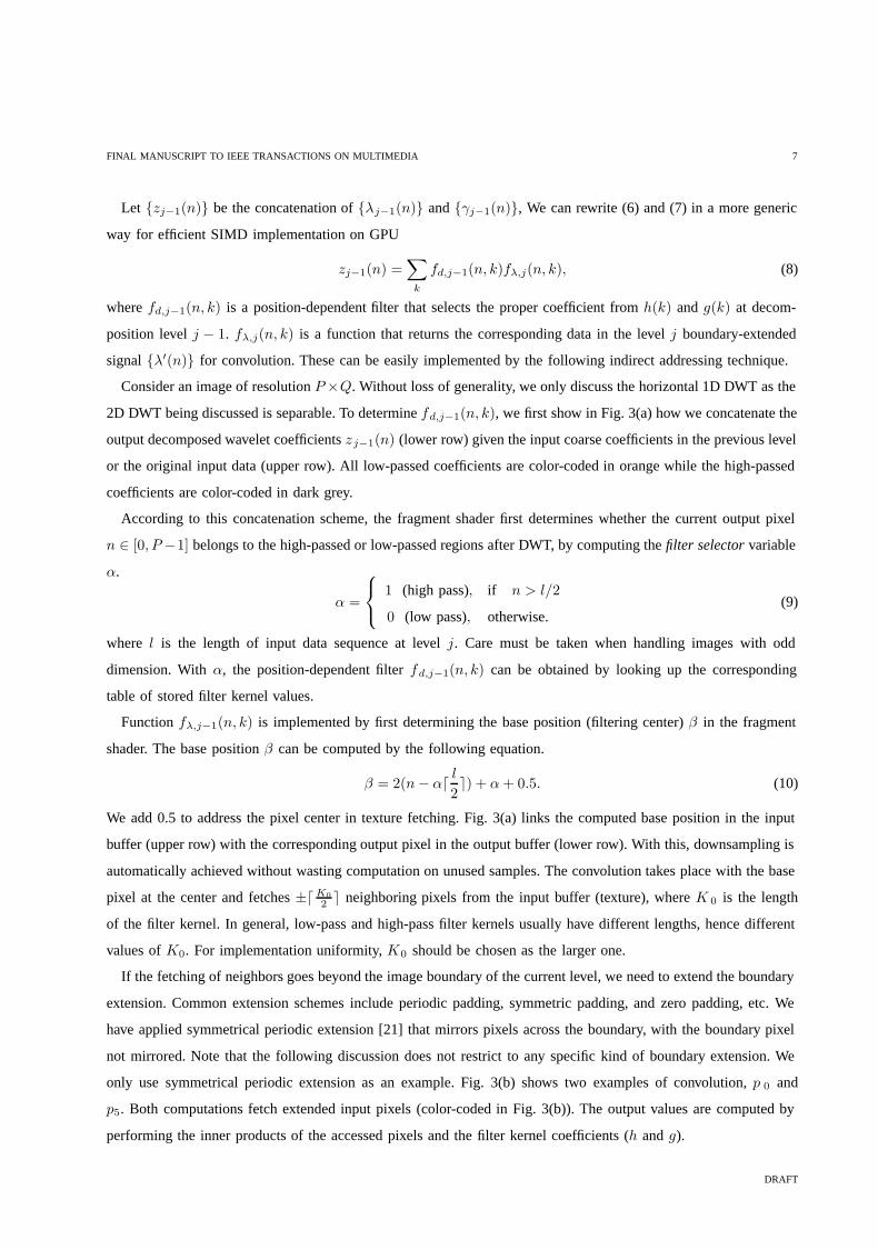
where fz,j−1(n, k) returns the corresponding data in the up-sampled and boundary-extended signal of {z(n)} at
level j − 1. This is efficiently implemented by first computing an indirect address table as shown in Fig. 5. That is,
we do not actually perform the upsampling nor interleaving, but we perform them virtually via looking up these
precomputed indirect addresses. Note that the boundaries have to be extended before the interleaving as illustrated
in Fig. 5.
Fig. 5. Virtual upsampling and interleaving via precomputing and looking up indirect addresses.
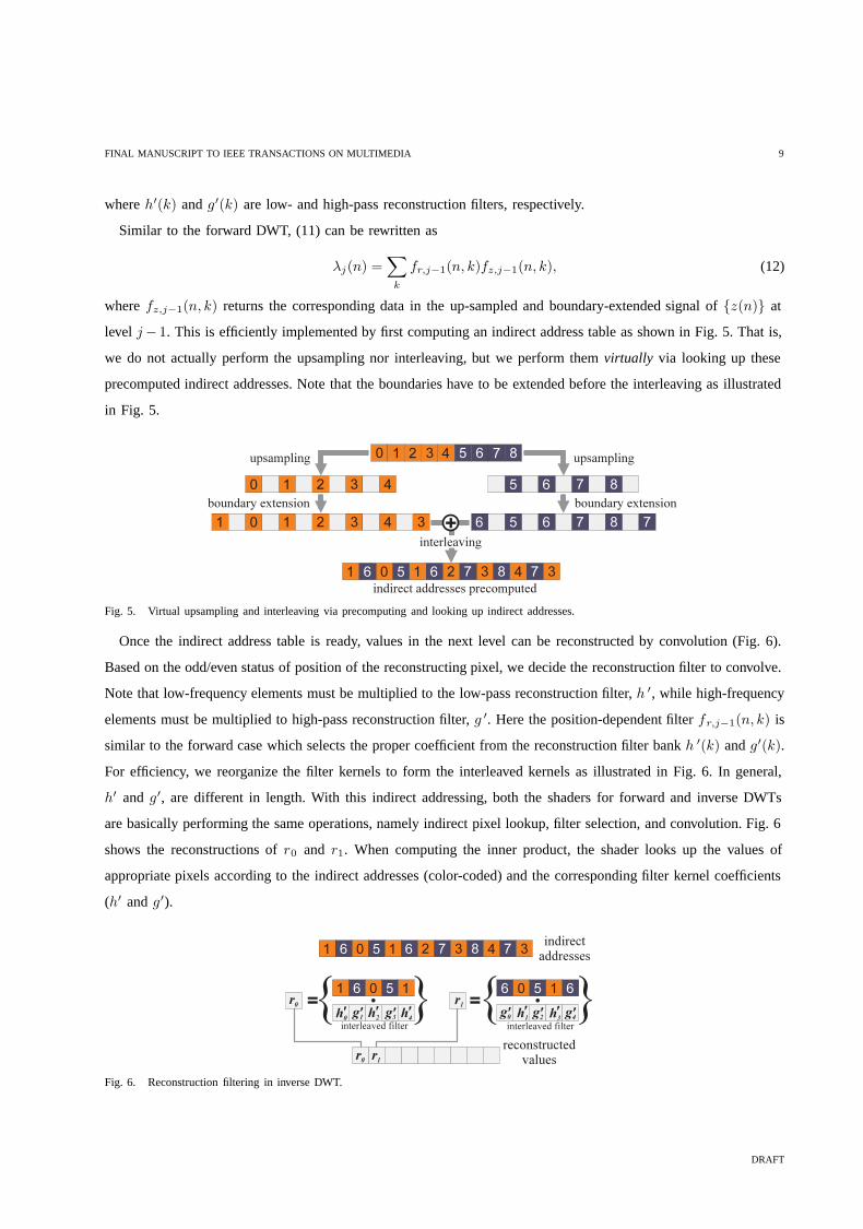
Once the indirect address table is ready, values in the next level can be reconstructed by convolution (Fig. 6).
Based on the odd/even status of position of the reconstructing pixel, we decide the reconstruction filter to convolve.
Note that low-frequency elements must be multiplied to the low-pass reconstruction filter, h ′, while high-frequency
elements must be multiplied to high-pass reconstruction filter, g ′. Here the position-dependent filter fr,j−1(n, k) is
similar to the forward case which selects the proper coefficient from the reconstruction filter bank h ′(k) and g′(k).
For efficiency, we reorganize the filter kernels to form the interleaved kernels as illustrated in Fig. 6. In general,
h′ and g′, are different in length. With this indirect addressing, both the shaders for forward and inverse DWTs
are basically performing the same operations, namely indirect pixel lookup, filter selection, and convolution. Fig. 6
shows the reconstructions of r0 and r1. When computing the inner product, the shader looks up the values of
appropriate pixels according to the indirect addresses (color-coded) and the corresponding filter kernel coefficients
(h′ and g′).
Fig. 6. Reconstruction filtering in inverse DWT.
DRAFT

FINAL MANUSCRIPT TO IEEE TRANSACTIONS ON MULTIMEDIA 10
0 0.5 1 1.5 2 2.5 3 3.5 4 4.50
2
4
6
8
10
12
14DWT Execution Time
time
(sec
)
image size (Million Pixels)
Software DWTGPU DWT
Fig. 7. Timing comparison: software versus GPU DWT
VII. RESULTS AND APPLICATIONS
A. Hardware-Accelerated JPEG2000 Encoding
DWT has been identified as a time-consuming part of the lossy JPEG2000 encoding [5]. Especially when the
resolution of image is high, the DWT processing time becomes dominant. We have integrated our GPU-based
DWT engine into the popular JPEG2000 still image codec, JasPer [5], which is a free software-based reference
implementation of the codec specified in the JPEG-2000 Part-1 standard (i.e., ISO/IEC 15444-1). Its encoding
speed has been significantly increased with our DWT shader. Our implementation adopts OpenGL and Cg for
shader development. The latest OpenGL standard features including Frame Buffer Object have been utilized. The
evaluation is conducted on a PC with AMD Athlon 64x2 dual core processor 3800+ 2.01 GHz, 2GB memory, and
GeForce 7800 GTX.
We compared the execution time of GPU convolution-based DWT with the software lifting-based JasPer. Seven
test images ranging from 128×128 to 2048×2048. In the experiment, the whole image is referred as one tile for
DWT, instead of multiple independent tiles. The DWT used is Daubechies 9/7 wavelet. Five levels of decomposition
are carried out. Fig. 7 shows the timing statistics that compares the original software codec with ours. Instead of
measuring the image dimension, we measure the number of pixels in the unit of million pixels which is commonly
used in digital camera context. For low-resolution images, the speed of the GPU DWT is a bit poorer than the
software one because of the overhead of GPU initialization and data transfer. As the image size is raised to around
3.6 million pixels (about 600 × 600). Our codec outperforms the software one. The speedup is apparent for encoding
high-resolution images. This shows the advantage of parallel processing in SIMD-based GPU.
For a fair comparison, we have accounted for all overheads of using GPU, these include data conversion,
initialization and texture creation, etc. The breakdown of execution time is shown in Table I. The total computation
time of our GPU-based DWT is shown in column “GPU Total” of Table I. The timing for software lifting
implementation of DWT (“Software Total”) is also presented for comparison. Since we modified the JasPer package
to include our GPU module, the peripheral computations such as the subsequent entropy coding and file I/O are
DRAFT

FINAL MANUSCRIPT TO IEEE TRANSACTIONS ON MULTIMEDIA 11
TABLE I
BREAKDOWN OF COMPUTATIONAL TIME (SEC)
Image Soft Total GPU Total OpenGL Texture DWT Others
1282 0.016 0.468 0.218 0.015 0.234 0.001
2562 0.031 0.500 0.218 0.032 0.234 0.016
5122 0.344 0.578 0.219 0.078 0.234 0.047
10242 2.593 0.813 0.219 0.218 0.235 0.141
12802 2.688 1.000 0.219 0.313 0.234 0.234
20482 12.312 1.672 0.219 0.625 0.234 0.594
exactly the same for both software and GPU executions. Therefore the time of those peripheral computations are
excluded in “GPU Total” and “Software Total”. “OpenGL” shows the time for initializing OpenGL and Cg systems,
which is more or less constant. “Texture” accounts for the time for texture and buffer creation. It increases as the
data size increases. For large images, the computation time for DWT occupies only a small portion of the whole
execution time due to the parallel processing nature of GPU. The advantage of parallization is demonstrated with
this almost constant DWT time, regardless of the image resolution. “Others” refers to the time for other operations
as well as data conversion and transfer, therefore it also depends on the data size.
B. Stylized Image Processing and Texture-illuminance Decoupling
Our GPU-based DWT engine allows us to achieve fast wavelet-based multiresolution image processing which
offers various effects, even images are of high resolution. Hence, we combine, remove, or scale the wavelet
coefficients in different subbands and in different color spaces (RGB or Y UV ) to achieve the desired effects. As
illustrated in Fig. 8, the bumpy feature (instead of the yellowish color) of the middle bean image is transferred to
the Starry Night painting (left) by combining the high-frequency subbands in the Y channel of both images while
removing the lowest frequency subband of the bean image. We take the maximum between two corresponding
coefficients to maintain the details from both images. The fast wavelet transform allows the designer to rapidly
evaluate the visual results from wavelet domain processing.
Fig. 8. Fast image stylizing by combining coefficients in wavelet domain. The element-wise max operation can also be achieved in the shader.
Sometimes when we acquire textures by taking photographs, the illumination condition is usually not controlled.
If the illumination only introduces slow intensity change in the acquired image (i.e. low-frequency component), it is
DRAFT

FINAL MANUSCRIPT TO IEEE TRANSACTIONS ON MULTIMEDIA 12
possible to decouple the contribution due to the uncontrolled illumination from the desired texture. Fig. 9 illustrates
such application. We first remove high-frequency subbands and generate the illuminance image using inverse DWT.
By dividing the original image with this illuminance image, we obtain an “illumination-constant” decal map which
is ready for texture mapping. Note that simple element-wise operations (like max and division) can also be easily
implemented in the shader.
Fig. 9. Fast texture-illuminance decoupling.
C. Geometric Deformation in Wavelet Domain
We have applied our GPU-based DWT engine to geometric deformation in which the designer can modify control
points of a NURBS 3D model [22] in wavelet domain. The control points in 3D are in grid structure and stored
in memory as three 2D arrays, one for each x-, y-, and z-coordinates. DWT is then applied to these control-point
arrays to obtain wavelet coefficients at desired decomposition level. The designer can arbitrarily scale the wavelet
coefficients in different frequency subbands to achieve the desired effect.
Fig. 10 shows three deformed heads along with the scaling configurations of wavelet subbands. The subband
with no scaling is color-coded in grey. The subbands being scaled up and down are color-coded in black and white
respectively. As coefficients in different subband influence the geometry in different scales, the designer can focus
on the semantic rather than the spatial position of control points.
Fig. 10. Three different wavelet-based geometric designs.
VIII. CONCLUSIONS
We have demonstrated a simple but powerful and cost-effective solution to implement 2D DWT on the consumer-
level GPU. No tailor-made and expensive DWT hardware is needed to achieve such performance. It can be
implemented on any SIMD-based GPU comes with normal configuration of PCs. The proposed method unifies
the mathematically-different forward and inverse DWT. Different wavelet filter kernels and boundary extension
DRAFT

FINAL MANUSCRIPT TO IEEE TRANSACTIONS ON MULTIMEDIA 13
schemes can be easily incorporated by modifying the filter kernel values and indirect address table respectively.
We have demonstrated its applicability in wavelet-based geometric deformation, stylized image processing, texture-
illuminance decoupling, and JPEG2000 encoding. More information and demo programs (released since January
2004) are available at:
http://www.cse.cuhk.edu.hk/∼ttwong/software/dwtgpu/dwtgpu.html
ACKNOWLEDGMENT
We would like to thank Liang Wan for reimplementing the software with the latest OpenGL standard features.
This project is supported by the Research Grants Council of the Hong Kong Special Administrative Region, under
RGC Earmarked Grants (Project No. CUHK417005) and a research grant from City University of Hong Kong
(Project No. 7001819).
REFERENCES
[1] T.-T. Wong and C.-S. Leung, “Compression of illumination-adjustable images,” IEEE Transactions on Circuits and Systems for Video
Technology (special issue on Image-based Modeling, Rendering and Animation), vol. 13, no. 11, pp. 1107–1118, November 2003.
[2] P.-M. Lam, C.-S. Leung, and T.-T. Wong, “A compression method for a massive image data set in the image-based rendering application,”
Signal Processing: Image Communication, vol. 19, no. 8, pp. 741–754, September 2004.
[3] Z. Wang, C.-S. Leung, Y.-S. Zhu, and T.-T. Wong, “Data compression with spherical wavelets and wavelets for the image-based relighting,”
Computer Vision and Image Understanding (special issue on Model-based and Image-based 3D Scene Representation for Interactive
Visualization), vol. 96, no. 3, pp. 327–344, December 2004.
[4] A. Finkelstein, C. E. Jacobs, and D. H. Salesin, “Multiresolution video,” in Proceedings of the 23rd annual conference on Computer
graphics and interactive techniques, 1996.
[5] M. D. Adams and F. Kossentini, “JasPer: A software-based JPEG-2000 codec implementation,” in Proceedings of IEEE ICIP, 2000.
[6] W. Sweldens, “The lifting scheme: A construction of second generation wavelets,” SIAM Journal on Mathematical Analysis, vol. 29, no. 2,
pp. 511–546, 1998.
[7] K. Andra, C. Chakrabarti, and T. Acharya, “A VLSI architecture for lifting based forward and inverse wavelet transform,” IEEE Transactions
on Signal Processing, vol. 50, pp. 966–977, April 2002.
[8] C.-T. Huang, P.-C. Tseng, and L.-G. Chen, “Hardware implementation of shape-adaptive discrete wavelet transform with the JPEG defaulted
(9,7) filter bank,” in Proceedings of ICIP 2003, 2003.
[9] W. R. Mark, R. S. Glanville, K. Akeley, and M. J. Kilgard, “Cg: A system for programming graphics hardware in a C-like language,” in
ACM Transactions on Graphics (TOG), 2003.
[10] J. Bolz, I. Farmer, E. Grinspun, and P. Schreoder, “Sparse matrix solvers on the GPU: conjugate gradients and multigrid,” in ACM
Transactions on Graphics (TOG), 2003.
[11] J. Kruger and R. Westermann, “Linear algebra operators for GPU implementation of numerical algorithms,” in ACM TOG, 2003.
[12] K. Moreland and E. Angel, “The FFT on a GPU,” in Proceedings of HWWS, 2003.
[13] T.-T. Wong, S.-H. Or, and C.-W. Fu, “Real-time relighting of compressed panoramas,” in Graphics Programming Methods, J. Lander, Ed.
Charles Rivers Media, 2003, pp. 375–288.
[14] T.-T. Wong, C.-S. Leung, and K.-H. Choy, “Lighting precomputation using the relighting map,” in Shader X3: Advanced Rendering with
Direct X and OpenGL, W. Engel, Ed. Charles Rivers Media, 2004.
[15] M. Hopf and T. Ertl, “Hardware accelerated wavelet transformations,” in Proceedings of EG/IEEE TCVG Symposium on Visualization,
2000.
[16] A. Garcia and H.-W. Shen, “GPU-based 3d wavelet reconstruction with tileboarding,” The Visual Computer, vol. 21 (special issue on
Pacific Graphics 2005, no. 8-10, pp. 755–763, 2005.
DRAFT

FINAL MANUSCRIPT TO IEEE TRANSACTIONS ON MULTIMEDIA 14
[17] B. M. Oh, M. Chen, J. Dorsey, and F. Durand, “Image-based modeling and photo editing,” in Proceedings of the 28th annual conference
on Computer graphics and interactive techniques, 2001, pp. 433–442.
[18] C. K. Chui, An Introduction to Wavelets. Academic Press, 1992.
[19] E. J. Stollnitz, T. D. DeRose, and D. H. Salesin, Wavelets for Computer Graphics, Theory and Applications. Morgan Kaufmann Publishers,
Inc, 1996.
[20] I. Daubechies, Ten Lectures on Wavelets. SIAM, 1992.
[21] G. Strang and T. Nguyen, Wavelets and Filter Banks. Cambridge, MA: Wellesley-Cambridge, 1996.
[22] L. Piegl, “On NURBS: A survey,” IEEE Computer Graphics and Applications, vol. 11, no. 1, pp. 55–71, January 1991.
Tien-Tsin Wong (M’94) received the B.Sci., M.Phil., and Ph.D. degrees in computer science from the Chinese University of Hong Kong in
1992, 1994, and 1998, respectively. Currently, he is a Professor in the Department of Computer Science & Engineering, the Chinese University
of Hong Kong. His main research interest is computer graphics, including image-based rendering, precomputed lighting, non-photorealistic
rendering, natural phenomena modeling, multimedia data compression, and visualization. He received “IEEE Transactions on Multimedia Prize
Paper Award 2005” and “Young Researcher Award 2004”.
Chi-Sing Leung (M’05) received the B.Sc. degree in electronics, the M.Phil. degree in information engineering, and the Ph.D. degree in
computer science from the Chinese University of Hong Kong in 1989, 1991, and 1995, respectively. He is currently an Associate Professor with
the Department of Electronic Engineering, City University of Hong Kong. His research interests include neural computing, data mining, and
computer graphics. He has been working on image-based rendering for 10 years. He proposed a two-level compression method for illumination
adjustable images and the corresponding real-time rendering methods. He received the IEEE Transactions on Multimedia 2005 Prize Paper
Award for the paper titled, “The Plenoptic Illumination Function” in IEEE Trans. on Multimedia, Vol. 4, Issue 3, September, 2002. He has
published over 60 international journal papers. He was the Guest Editor of the journal Neural Computing and Applications.
Pheng-Ann Heng (M’92– SM’06) received the B.Sc. degree from the National University of Singapore in 1985, and the M.Sc. degree in
computer science, the M.A. degree in applied mathematics, and the Ph.D. degree in computer science, all from Indiana University, Bloomington,
in 1987, 1988, and 1992, respectively.
Currently, he is a Professor in the Department of Computer Science and Engineering, The Chinese University of Hong Kong (CUHK), Shatin.
In 1999, he set up the Virtual Reality, Visualization and Imaging Research Centre at CUHK and serves as the Director of the centre. He is also
the Director of the Human-Computer Interaction Research Centre, Shenzhen Institute of Advanced Integration Technology, Chinese Academy of
Science/Chinese University of Hong Kong. His research interests include virtual reality applications in medicine, visualization, medical imaging,
human-computer interface, rendering and modeling, interactive graphics and animation.
Wang Jianqing receives the BSc. degree in Information Technology from City University of Hong Kong in 2002 and the MPhil. degree in
Computer Science from The Chinese University of Hong Kong in 2004. He is currently a software engineer in media technology team at Entone
Technologies Ltd, developing MPEG2 and H.264 IPTV products. His main research interest is computer graphics.
DRAFT


![IEEE TRANSACTIONS ON JOURNAL NAME, MANUSCRIPT ID 1 … · 2 IEEE TRANSACTIONS ON JOURNAL NAME, MANUSCRIPT ID formance for identifying Alzheimer’s disease [20, 21], fragile X syndrome](https://img.pdfslide.us/doc/110x75/5d5b609588c993d9498bb549/ieee-transactions-on-journal-name-manuscript-id-1-2-ieee-transactions-on-journal.jpg)