Embed Size (px)
Citation preview

GEOTECHNICAL INVESTIGATION
TEXAS AVENUE (FM 1765) DRAINAGE IMPROVEMENTS
FROM 6TH STREET TO BAY STREET
CITY OF TEXAS CITY, GALVESTON COUNTY, TEXAS
REPORT NO. 1140255501
Reported to:
ARKK ENGINEERS, INC.
Houston, Texas
Reported by:
GEOTEST ENGINEERING, INC.
Houston, Texas
Key Map Nos. 738 H
TABLE OF CONTENTS
Page
EXECUTIVE SUMMARY ........................................................................................... 1
1.0 INTRODUCTION
1.1 Location and Description of Project ............................................................ 3
1.2 Scope of Work ............................................................................................. 3
2.0 FIELD EXPLORATION .................................................................................... 5
3.0 LABORATORY TESTING PROGRAM ............................................................ 6
4.0 GENERAL SUBSURFACE CONDITIONS
4.1 Existing Pavement ....................................................................................... 7
4.2 Subsurface Soil ............................................................................................ 7
4.3 Water Levels ................................................................................................ 8
5.0 GEOTECHNICAL RECOMMENDATIONS
5.1 General ......................................................................................................... 9
5.2 Open-Cut Excavation .................................................................................. 9
5.2.1 Geotechnical Parameters ................................................................ 9
5.2.2 Excavation Stability ....................................................................... 9
5.2.3 Groundwater Control ...................................................................... 11
5.2.4 Bedding and Backfill for Storm Sewer .......................................... 11
5.3 Pavement Structure Design ....................................................................... 11
5.3.1 Design Parameters .......................................................................... 12
5.3.2 Recommended Pavement Section .................................................. 13
5.3.3 Preparation of Pavement Subgrade ................................................. 13
6.0 PROVISIONS .......................................................................................................... 15

ILLUSTRATIONS
Figure
Vicinity Map ................................................................................................................... 1
Plan of Borings ............................................................................................................... 2
Boring Log Profiles ........................................................................................................ 3
Symbols and Abbreviations Used on Boring Log Profiles ............................................ 4
Excavation Support Earth Pressure ................................................................................ 5.1 and 5.2
Stability of Bottom for Braced Cut ................................................................................ 6
TABLES
Table
Geotechnical Design Parameter Summary: Open-Cut Excavation ............................. 1
APPENDIX A
Figure
Log of Borings ................................................................................................................ A-1 thru A-4
Symbols and Terms Used on Boring Logs .................................................................... A-5
APPENDIX B
Figure
Grain Size Distribution Curves ...................................................................................... B-1
Geotest Engineering, Inc. Report No. 1140255501
Texas Avenue (FM 1765) Drainage Improvements January 7, 2021
City of Texas City, Texas
1
EXECUTIVE SUMMARY
A geotechnical investigation was conducted for the proposed Texas Avenue (FM 1765)
Drainage Improvements project from 6th Street to Bay Street in the City of Texas City, Galveston
County, Texas. The project includes replacement of approximately 2,900 LF of the existing
paving along the project alignment with new concrete pavement, along with proposed 5'×5' RCB
storm sewer construction/replacement. Based on the information provided, we understand that
the invert depth of the proposed 5'×5' RCB storm sewer ranges from 9 to 10 feet (elevations
ranges from -2.8 to -4.0 feet), and will be installed primarily by open-cut method of construction.
This study included drilling and sampling of four (4) soil borings each to a depth of 15
feet, performing laboratory tests on recovered soil samples, performing engineering analyses and
preparing a geotechnical report.
The principal findings and conclusions developed from this investigation are summarized
below:
• The existing pavement along Texas Avenue from 6th Street to Bay Street, as obtained in
borings GB-1 through GB-4, consists of 2.0 to 5.5 inches of asphalt over 4.5 to 6.5 inches
of concrete, except near boring GB-4. At boring GB-4, the existing pavement consists of
about 1-inch of asphalt over 10 inches of limestone with asphalt and sandy clay mix base.
• The subsurface soils below the existing pavement, as revealed by borings GB-1 through
GB-3, consist of cohesive soils underlain by cohesionless soils, except in boring GB-4,
where cohesive soils were encountered to the explored depth of 15 feet. The cohesive
soils consist of soft to very stiff gray, brown, dark gray, and yellowish brown and gray fat
clay, lean clay with sand, sandy lean clay, and sandy silty clay. Cohesionless soils
consists of loose to dense brown and gray, and yellowish-brown silty sand, clayey sand
and poorly graded sand with silt was encountered at depths ranging from 6 to 12 feet in
borings GB-1 through GB-3.
Geotest Engineering, Inc. Report No. 1140255501
Texas Avenue (FM 1765) Drainage Improvements January 7, 2021
City of Texas City, Texas
2
• Groundwater was first encountered at depths ranging from 12 to 14 feet all borings. The
water level, measured 20 minutes after water was first encountered, ranged from 5.3 to
7.8 feet in these borings.
• All excavation operations should be in accordance with OSHA Standards, and Galveston
County Standard Specification, Section 01526, “Trench Safety Systems.”
• The bedding and backfill for the proposed storm sewer should be in accordance with ARKK
Standard Specification, Section 02227, and Galveston County Standard Specification,
Section 02227, “Excavation and Backfill for Utilities.”
• The recommended pavement section and subgrade stabilization for Texas Avenue (FM
1765) reconstruction are presented in Section 5.3 of this report.
Geotest Engineering, Inc. Report No. 1140255501
Texas Avenue (FM 1765) Drainage Improvements January 7, 2021
City of Texas City, Texas
3
1.0 INTRODUCTION
1.1 Location and Description of Project
A geotechnical investigation was conducted for the Texas Avenue (FM 1765) Drainage
Improvements from 6th Street to Bay Street in the City of Texas City, Galveston County, Texas,
within the Key Map Page No. 738 Grid H.
The project includes replacement of approximately 2,900 LF of the existing paving along
the project alignment with new concrete pavement, along with proposed 5'×5' RCB storm sewer
construction/replacement. Based on the information provided, we understand that the invert
depth of the proposed 5'×5' RCB storm sewer ranges from 9 to 10 feet (elevations ranges from -
2.8 to -4.0 feet), and will be installed primarily by open-cut method of construction. The vicinity
map of the project alignment is shown on Figure 1.
1.2 Scope of Work
The purpose of this investigation was to evaluate the soil and groundwater (if any)
conditions along Texas Avenue in the City of Texas City, and to provide geotechnical
recommendations for the proposed paving and drainage improvements. The scope of this
investigation consisted of the following tasks:
• Cored the existing pavement along Texas Avenue to obtain the existing pavement
thickness and for boring access.
• Drilled and sampled four (4) soil borings each to a depth of 15 feet along Texas Avenue
(FM 1765) from 6th Street to Bay Street.
• Performed appropriate laboratory tests on selected representative soil samples to develop
the engineering properties of the soil.
Geotest Engineering, Inc. Report No. 1140255501
Texas Avenue (FM 1765) Drainage Improvements January 7, 2021
City of Texas City, Texas
4
• Performed engineering analyses to develop geotechnical recommendations for pavement
thickness including subgrade stabilization for the pavement construction, bedding and
backfill and water level control for open cut construction for storm sewer and water line
installation.
• Prepared a geotechnical investigation report including field and laboratory data and
geotechnical recommendations.
Geotest Engineering, Inc. Report No. 1140255501
Texas Avenue (FM 1765) Drainage Improvements January 7, 2021
City of Texas City, Texas
5
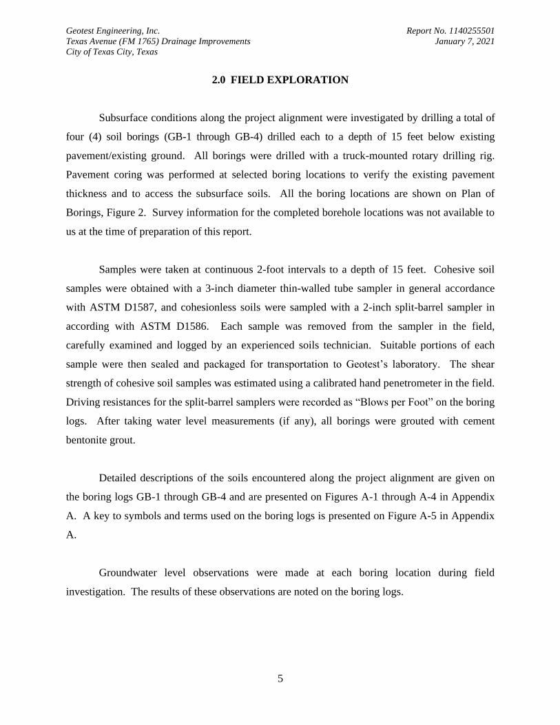
2.0 FIELD EXPLORATION
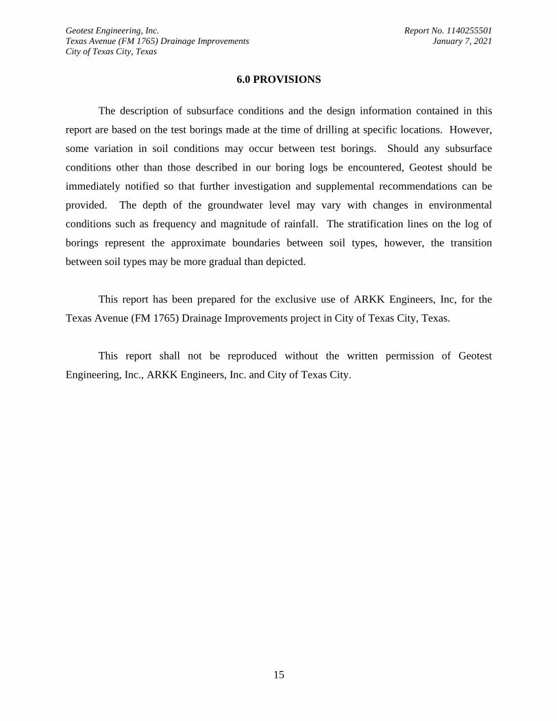
Subsurface conditions along the project alignment were investigated by drilling a total of
four (4) soil borings (GB-1 through GB-4) drilled each to a depth of 15 feet below existing
pavement/existing ground. All borings were drilled with a truck-mounted rotary drilling rig.
Pavement coring was performed at selected boring locations to verify the existing pavement
thickness and to access the subsurface soils. All the boring locations are shown on Plan of
Borings, Figure 2. Survey information for the completed borehole locations was not available to
us at the time of preparation of this report.
Samples were taken at continuous 2-foot intervals to a depth of 15 feet. Cohesive soil
samples were obtained with a 3-inch diameter thin-walled tube sampler in general accordance
with ASTM D1587, and cohesionless soils were sampled with a 2-inch split-barrel sampler in
according with ASTM D1586. Each sample was removed from the sampler in the field,
carefully examined and logged by an experienced soils technician. Suitable portions of each
sample were then sealed and packaged for transportation to Geotest’s laboratory. The shear
strength of cohesive soil samples was estimated using a calibrated hand penetrometer in the field.
Driving resistances for the split-barrel samplers were recorded as “Blows per Foot” on the boring
logs. After taking water level measurements (if any), all borings were grouted with cement
bentonite grout.
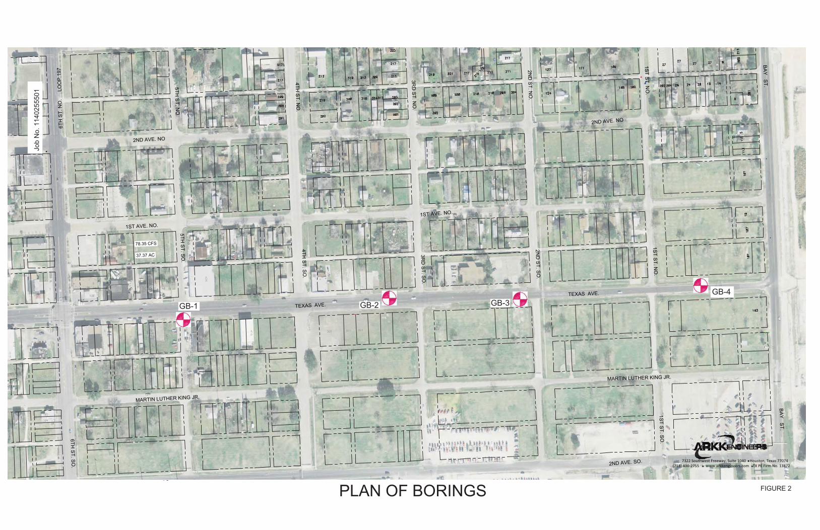
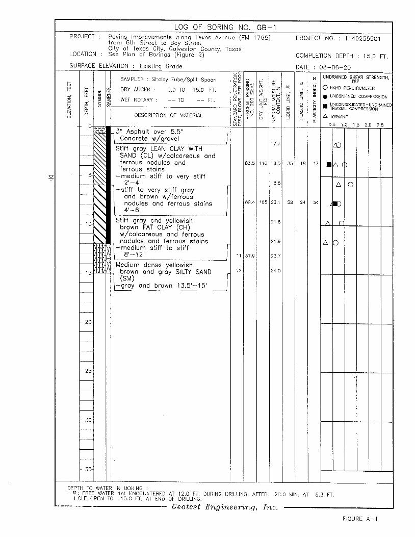
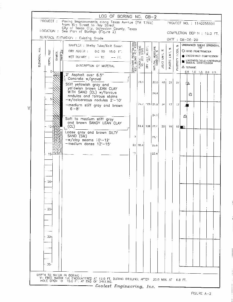
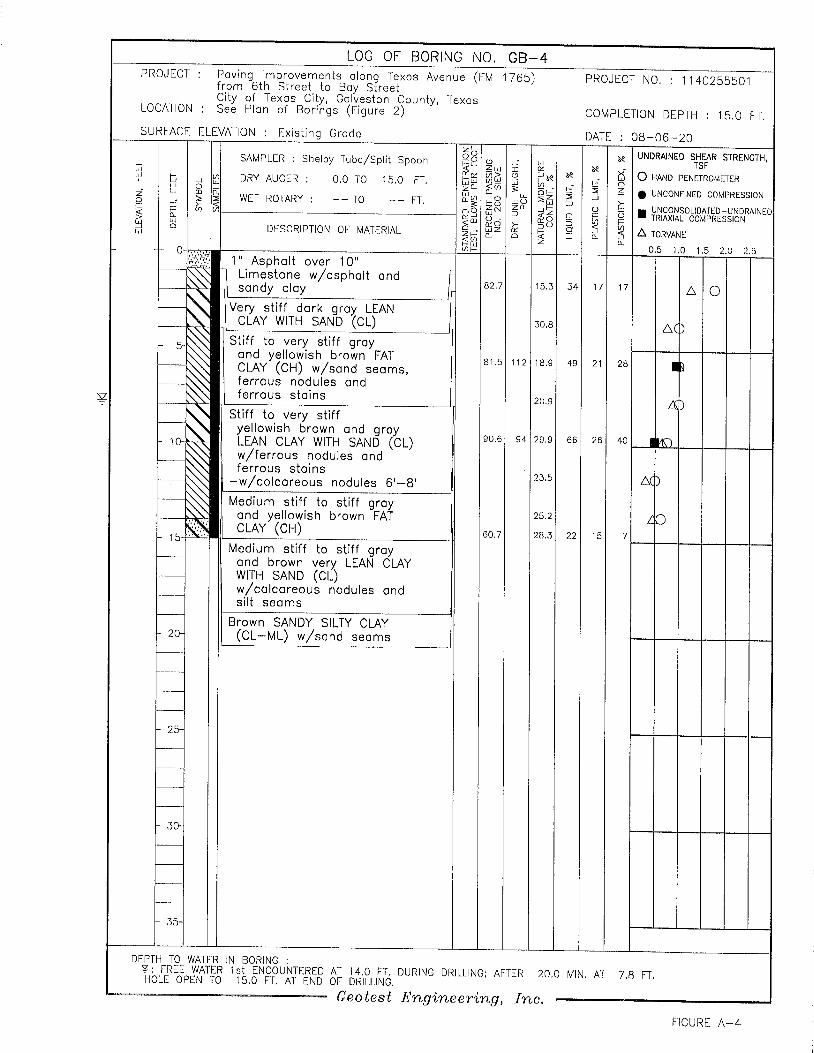
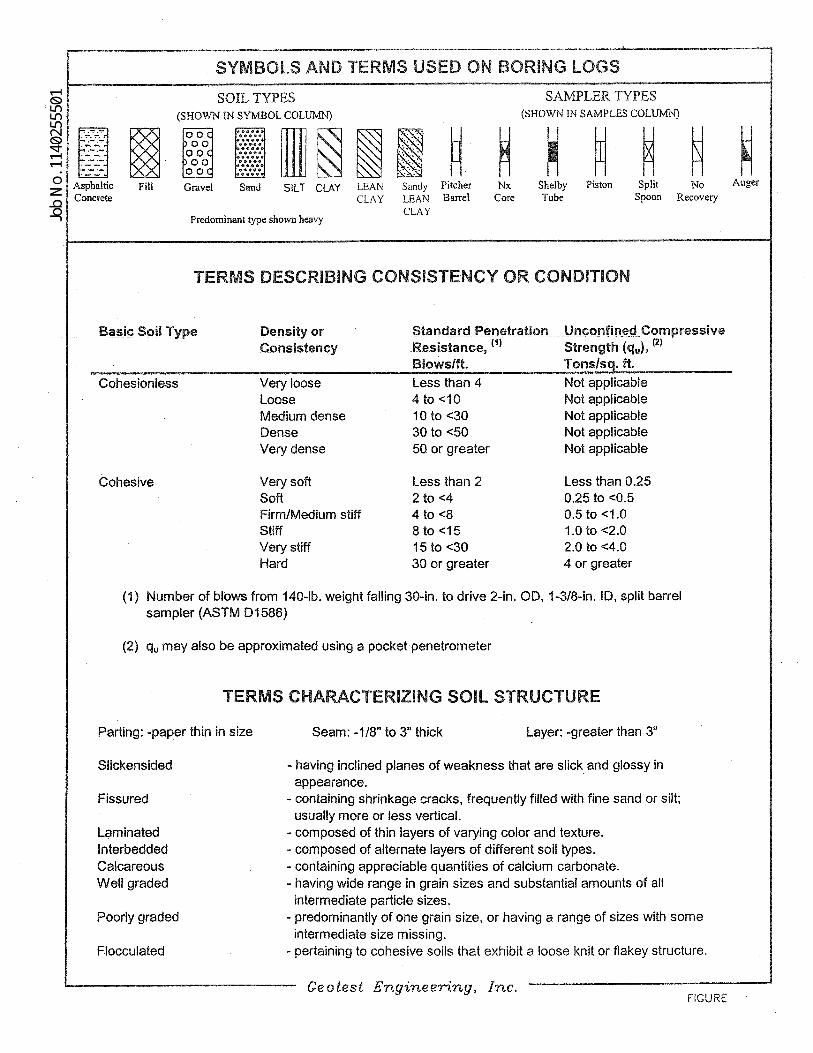
Detailed descriptions of the soils encountered along the project alignment are given on
the boring logs GB-1 through GB-4 and are presented on Figures A-1 through A-4 in Appendix
A. A key to symbols and terms used on the boring logs is presented on Figure A-5 in Appendix
A.
Groundwater level observations were made at each boring location during field
investigation. The results of these observations are noted on the boring logs.

Geotest Engineering, Inc. Report No. 1140255501
Texas Avenue (FM 1765) Drainage Improvements January 7, 2021
City of Texas City, Texas
6
3.0 LABORATORY TESTING PROGRAM
The laboratory testing program was designed to evaluate the pertinent physical properties
and shear strength characteristics of the subsurface soils. Classification tests were performed on
selected samples to aid in soil classification.
Undrained shear strengths of selected cohesive samples were measured by
unconsolidated undrained (UU) triaxial compression tests (ASTM D2850). The results of the
UU triaxial compression tests are plotted on the boring logs as solid squares. The shear strength
of cohesive samples was measured in the field with a calibrated hand penetrometer and also in
the laboratory with a Torvane. The shear strength values obtained from the penetrometer and
Torvane are plotted on the boring logs as open circles and triangles, respectively.
Moisture content and dry unit weight were measured for each unconfined compression
test and UU triaxial compression test samples. Moisture content measurements (ASTM D2216)
were also made on other samples to establish the moisture profile at each boring location.
Atterberg limit tests (ASTM D4318) were performed on soil samples to measure plasticity
characteristics. Percent passing No. 200 sieve (ASTM D1140) tests were also performed on
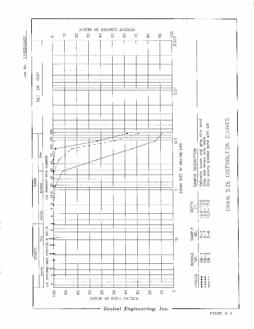
selected samples. Sieve analysis (ASTM D6913) was performed on selected sample for
classification and grain size analysis. The result of all these tests are plotted or summarized on
the boring logs GB-1 through GB-4 and are presented on Figures A-1 through A-4 in Appendix
A. The grain size distribution curves are presented on Figure B-1 in Appendix B.
Geotest Engineering, Inc. Report No. 1140255501
Texas Avenue (FM 1765) Drainage Improvements January 7, 2021
City of Texas City, Texas
7
4.0 GENERAL SUBSURFACE CONDITIONS
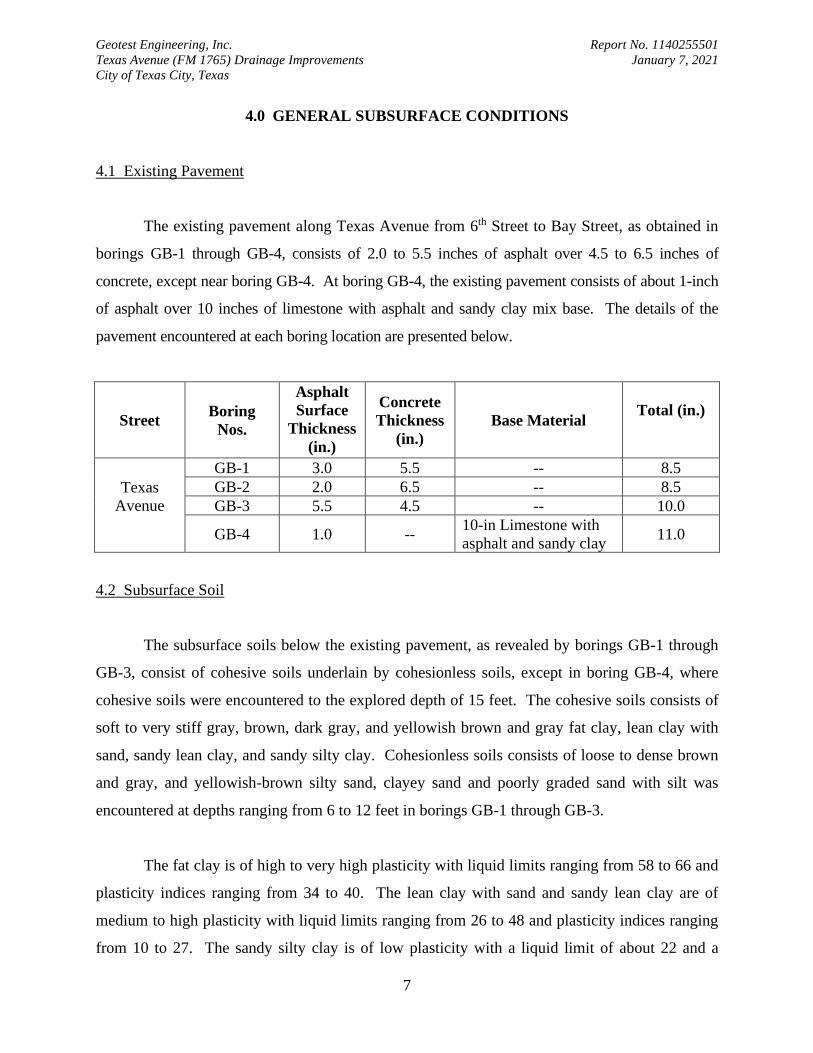
4.1 Existing Pavement
The existing pavement along Texas Avenue from 6th Street to Bay Street, as obtained in
borings GB-1 through GB-4, consists of 2.0 to 5.5 inches of asphalt over 4.5 to 6.5 inches of
concrete, except near boring GB-4. At boring GB-4, the existing pavement consists of about 1-inch
of asphalt over 10 inches of limestone with asphalt and sandy clay mix base. The details of the
pavement encountered at each boring location are presented below.
Street Boring
Nos.
Asphalt
Surface
Thickness
(in.)
Concrete
Thickness
(in.)
Base Material
Total (in.)
Texas
Avenue
GB-1 3.0 5.5 -- 8.5
GB-2 2.0 6.5 -- 8.5
GB-3 5.5 4.5 -- 10.0
GB-4 1.0 -- 10-in Limestone with
asphalt and sandy clay 11.0
4.2 Subsurface Soil
The subsurface soils below the existing pavement, as revealed by borings GB-1 through
GB-3, consist of cohesive soils underlain by cohesionless soils, except in boring GB-4, where
cohesive soils were encountered to the explored depth of 15 feet. The cohesive soils consists of
soft to very stiff gray, brown, dark gray, and yellowish brown and gray fat clay, lean clay with
sand, sandy lean clay, and sandy silty clay. Cohesionless soils consists of loose to dense brown
and gray, and yellowish-brown silty sand, clayey sand and poorly graded sand with silt was
encountered at depths ranging from 6 to 12 feet in borings GB-1 through GB-3.
The fat clay is of high to very high plasticity with liquid limits ranging from 58 to 66 and
plasticity indices ranging from 34 to 40. The lean clay with sand and sandy lean clay are of
medium to high plasticity with liquid limits ranging from 26 to 48 and plasticity indices ranging
from 10 to 27. The sandy silty clay is of low plasticity with a liquid limit of about 22 and a
Geotest Engineering, Inc. Report No. 1140255501
Texas Avenue (FM 1765) Drainage Improvements January 7, 2021
City of Texas City, Texas
8
plasticity of about 7. The fines content (passing No. 200 sieve) of fat clay ranges from 89 to 91
percent. The fines content of lean clay with sand ranges from 75 to 84 percent, and the fines
content of sandy lean clay and sandy silty clay ranges from 60 to 64 percent. The fines content
of silty sand and clayey sand ranges from 28 to 38 percent, the fines content of poorly graded
sand with sand is about 9 percent.
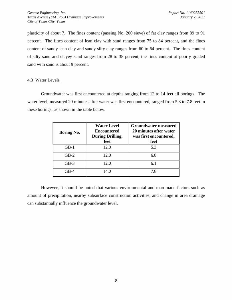
4.3 Water Levels
Groundwater was first encountered at depths ranging from 12 to 14 feet all borings. The
water level, measured 20 minutes after water was first encountered, ranged from 5.3 to 7.8 feet in
these borings, as shown in the table below.
Boring No.
Water Level
Encountered
During Drilling,
feet
Groundwater measured
20 minutes after water
was first encountered,
feet
GB-1 12.0 5.3
GB-2 12.0 6.8
GB-3 12.0 6.1
GB-4 14.0 7.8
However, it should be noted that various environmental and man-made factors such as
amount of precipitation, nearby subsurface construction activities, and change in area drainage
can substantially influence the groundwater level.
Geotest Engineering, Inc. Report No. 1140255501
Texas Avenue (FM 1765) Drainage Improvements January 7, 2021
City of Texas City, Texas
9
5.0 GEOTECHNICAL RECOMMENDATIONS
5.1 General
The project includes drainage and paving improvements along Texas Avenue (FM 1765)
from 6th Street to Bay Street in the City of Texas City, Galveston County, Texas. The details of
the project are presented in Section 1.1 of this report.
5.2 Open-Cut Excavation
5.2.1 Geotechnical Parameters. Based on the soil conditions revealed by the borings,
geotechnical parameters were developed for the design of open cut excavation for the proposed
5'×5' RCB storm sewer. The geotechnical design parameters for open cut excavation are
provided in Table 1. For design, the groundwater level should be assumed to exist at the ground
surface, since this condition may exist after a heavy rain or flooding.
5.2.2 Excavation Stability. The open excavations may be shored, laid back to a stable
slope or some other equivalent means used to provide safety for workers and adjacent structures.
The excavating and trenching operations should be in accordance with OSHA Standards, OSHA
2207, Subpart P, latest revision and Galveston County Standard Specification, Section 01526,
“Trench Safety Systems”.
• Excavation Shallower Than 5 Feet – For excavations that are less than 5 feet, the need
for protection should be evaluated by a competent person to examine the ground for
any indication of ground movement or potential cave-in. When any indication of
hazardous ground movement or potential cave-in is anticipated during construction,
adequate protective system should be provided for all excavation even that if the
excavations are shallower than 5 feet.
• Excavation Deeper Than 5 Feet - Excavations that are deeper than 5 feet should be
sloped, shored, sheeted, braced or laid back to a stable slope or supported by some
Geotest Engineering, Inc. Report No. 1140255501
Texas Avenue (FM 1765) Drainage Improvements January 7, 2021
City of Texas City, Texas
10
other equivalent means or protection such that workers are not exposed to moving
ground or cave-ins. The slopes and shoring should be in accordance with the trench
safety requirements per OSHA Standards. The following items provide design
criteria for trench stability.
(i) OSHA's Soil Type. Based on the soil conditions revealed by the borings and the
assumed groundwater level at surface, OSHA's soil type "C" should be used for
the determination of allowable maximum slope and/or the design of a shoring
system. For shoring deeper than 20 feet, an engineering evaluation is required.
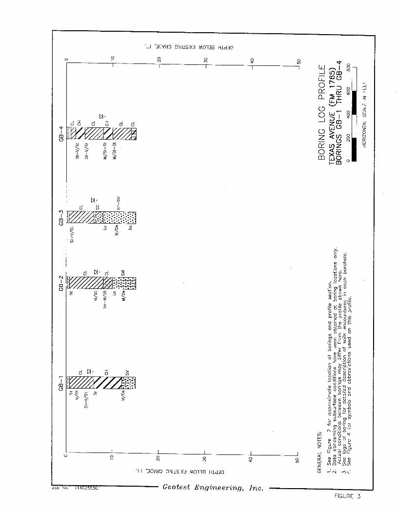
(ii) Excavation Support Earth Pressure. Based on the subsurface conditions indicated
by this investigation and laboratory testing results, the excavation support earth
pressure diagram was developed and is presented on Figures 5.1 and 5.2. The
pressure diagram can be used for the design of temporary excavation bracing. For
a trench box, a lateral earth pressure resulting from an equivalent fluid with a unit
weight of 97 pcf is recommended. The above value of equivalent fluid pressure is
based upon an assumption that the groundwater level is near the ground surface,
since these conditions may exist after a heavy rain or flooding. Effect of
surcharge loads at the ground surface should be added to the computed lateral
earth pressure. A surcharge load, q, will typically result in a lateral load equal to
0.5 q.
(iii) Bottom Stability. In braced cuts, if tight sheeting is terminated at the base of the
cut, the bottom of the excavation can become unstable under certain conditions.
The stability of the trench bottom is governed by the shear strength of the soils and
by the differential hydrostatic head. For cuts in cohesive soils as encountered in the
borings for excavation depths of 9 to 10 feet, stability of the bottom can be evaluated
in accordance with the procedure outlined on Figure 6. However, in cohesionless
soils (such as silty sand, clayey sand, and poorly graded sand with silt) as
encountered in borings GB-1 through GB-3 at the invert or within 3 feet of invert
Geotest Engineering, Inc. Report No. 1140255501
Texas Avenue (FM 1765) Drainage Improvements January 7, 2021
City of Texas City, Texas
11
depth, the excavation should be done after dewatering to avoid bottom stability
problems.
5.2.3 Groundwater Control. Excavations for the proposed utilities installation may
encounter groundwater seepage to varying degrees depending on groundwater conditions at the
time of construction and the location and depth of excavation. Based on the soil conditions
identified in the borings for the proposed utilities installation, all the excavations will be in
cohesive soils, and cohesive soils underlain by cohesionless soils. In cohesive soils as
encountered in the borings drilled for this study for the excavation depth of 10 feet, groundwater
may be managed by collection in trench bottom sumps for pumped disposal. However, for
excavations near borings GB-1 through GB-3, where cohesionless soils were encountered at
invert or within 3 feet of invert depth, dewatering may be required. Dewatering such as vacuum
well points up to 15 feet depth may be required to lower the water level to at least 3 feet below
the bottom of excavation. The dewatering system should be pumping well ahead of time before
excavation starts so that a steady state condition (groundwater elevation at least 3 feet below the
proposed excavation bottom) is achieved.
The contractor should verify the groundwater level at the time of construction and should
provide an adequate dewatering system, where required. The groundwater control should be
carried out in accordance with the ARKK Standard Specifications, Section 01563, and Galveston
County Standard Specification, Section 01563, “Control of Ground Water and Surface Water.”
5.2.4 Bedding and Backfill for Storm Sewer The bedding and backfill for the storm sewer
should be in accordance with ARKK Standard Specification, Section 02227, and Galveston County
Standard Specification, Section 02227, “Excavation and Backfill for Utilities.”
5.3 Pavement Structure Design
We understand that the existing paving along Texas Avenue (FM 1765) from 6th Street to
Bay Street, will be reconstructed with new concrete pavement with curb and gutter. The
pavement design presented below was developed in accordance with “AASHTO Guide for
Design of Pavement Structures,” 1993 Edition.
Geotest Engineering, Inc. Report No. 1140255501
Texas Avenue (FM 1765) Drainage Improvements January 7, 2021
City of Texas City, Texas
12
5.3.1 Design Parameters
Subgrade Soil Properties. California Bearing Ratio (CBR) tests were not within
the scope of this project. Therefore, the roadbed soil resilient modulus is
estimated based on physical properties and strength characteristics of the natural
subgrade soils. Based on the physical properties and strength characteristics of the
natural subgrade soils obtained from laboratory tests, the effective roadbed soil
resilient modulus (MR) was estimated to be about 1,941 psi from an assumed CBR
value of 1.0. Based on an estimated resilient modulus of the 8-inch lime-
stabilized subgrade, the effective modulus of subgrade reaction (k) is estimated to
be about 49 pci.
Traffic Data. No traffic count and vehicle classification data was provided to us at
the time of preparation of this report. Based on the information provided by
ARKK, the new concrete pavement section will be constructed in general
accordance with a standard pavement design. A traffic loading of 5.3 x 10⁶ kips
ESALs was calculated over a 30-year design period and was utilized for the
pavement design.
Other Design Parameters. Other design parameters used in the development of
rigid pavement thickness are given below:
Material Properties of Concrete:
Modulus of Elasticity of Concrete (Ec): 3,372,166 psi
Mean value of Modulus of Rupture of Concrete after 28 days
(S’c): 600 psi (based on compressive strength of 3,500 psi)
Load Transfer coefficient (J): 2.7
Drainage coefficient (Cd): 1.2
Overall Standard Deviation (So): 0.35
Reliability Level (R): 90%
Serviceability Index

Geotest Engineering, Inc. Report No. 1140255501
Texas Avenue (FM 1765) Drainage Improvements January 7, 2021
City of Texas City, Texas
13
Initial (Po): 4.5
Terminal (Pt): 2.25
Reinforcement Variables
Allowable Working Stress (fs): 45,000 psi (grade 60 steel)
Friction Factor (F): 1.8
5.3.2 Recommended Pavement Section
Based on the design parameters described above and the AASHTO design, the thickness of
rigid pavement was determined. The recommended pavement section is given below:
Pavement Course Thickness, inches
Reinforced Concrete 8
5% Lime-stabilized subgrade 8
For the 8-inch concrete pavement, the required longitudinal reinforcing steel for an
expansion joint spacing of 80 feet and transverse reinforcement steel for a pavement width of 24
feet back to back are given below for the grade 60 steel.
Pavement
Thickness
(Inches)
Longitudinal Steel Transverse Steel
Center to Center Spacing (in) Center to Center Spacing (in)
# 5 bars # 5 bars
8 24 30
5.3.3 Preparation of Pavement Subgrade
Based on the field and laboratory test data, the subgrade soils below the existing pavement
sections consist of medium to high plasticity lean clay with sand. These subgrade soil have high
volume change potential. Hence, lime stabilization of the clay subgrade soils will be required to
reduce the swelling and shrinkage potential, to accelerate the construction and provide a stable

Geotest Engineering, Inc. Report No. 1140255501
Texas Avenue (FM 1765) Drainage Improvements January 7, 2021
City of Texas City, Texas
14
subgrade on which to construct the pavement sections. The lean clay subgrade soils should be
stabilized with 5 percent lime (by dry unit weight of soil) to a depth of at least 8 inches. This
corresponds to approximately 33 pounds of lime per square yard based on a dry unit weight of 110
pcf. The actual percentage of lime should be confirmed by laboratory tests at the time of
construction.
Subgrade preparation for the proposed pavement after removing the existing pavement
should consist of stripping, proof-rolling, and stabilization. The following procedures for subgrade
preparation are recommended:
1. Strip the surficial soils to a suitable depth to remove all surficial vegetation and
achieve grade. In isolated areas where soft, compressible, or very loose soils are
encountered, additional stripping may be required.
2. After stripping, the exposed surface should be proof-rolled with a minimum of 3
passes of a 30-ton pneumatic-tired roller or a partially loaded truck utilizing a
tire pressure of approximately 90 psi. If rutting develops, the tire pressure
should be reduced. The purpose of the proof-rolling operation is to identify any
underlying zones or pockets of soft soils so these weak materials can be removed
and replaced.
3. Lime stabilization of cohesive subgrade should be performed in accordance with
ARKK Standard Specification, Section 02241, “Lime Stabilized Subgrade”.
Geotest Engineering, Inc. Report No. 1140255501
Texas Avenue (FM 1765) Drainage Improvements January 7, 2021
City of Texas City, Texas
15
6.0 PROVISIONS
The description of subsurface conditions and the design information contained in this
report are based on the test borings made at the time of drilling at specific locations. However,
some variation in soil conditions may occur between test borings. Should any subsurface
conditions other than those described in our boring logs be encountered, Geotest should be
immediately notified so that further investigation and supplemental recommendations can be
provided. The depth of the groundwater level may vary with changes in environmental
conditions such as frequency and magnitude of rainfall. The stratification lines on the log of
borings represent the approximate boundaries between soil types, however, the transition
between soil types may be more gradual than depicted.
This report has been prepared for the exclusive use of ARKK Engineers, Inc, for the
Texas Avenue (FM 1765) Drainage Improvements project in City of Texas City, Texas.
This report shall not be reproduced without the written permission of Geotest
Engineering, Inc., ARKK Engineers, Inc. and City of Texas City.

ILLUSTRATIONS
Figure
Vicinity Map .................................................................................................................. 1
Plan of Borings .............................................................................................................. 2
Boring Log Profiles ....................................................................................................... 3
Symbols and Abbreviations Used on Boring Log Profiles ......................................... 4
Excavation Support Earth Pressure .............................................................................. 5.1 and 5.2
Stability of Bottom for Braced Cut ............................................................................... 6

Geotest Engineering, Inc.FIGURE 1
VICINITY MAP
PAVING IMPROVEMENTS ALONG TEXAS AVENUE (FM 1765) FROM 6TH STREET TO BAY STREET
CITY OF TEXAS CITY, GALVESTON COUNTY, TEXAS
Job
No.
114
0255
501
PROJECTSITE
6TH
ST.
NO
.
4TH ST. N
O.
5TH ST. N
O.
3RD
ST. NO
.
2ND
ST. NO
.
BAY ST.
1ST ST. NO
.
1ST ST. SO.
BAY ST.
3RD
ST. SO.
2ND
ST. SO.
4TH ST. SO
.
5TH ST. SO
.
6TH ST. SO
.
2ND AVE. NO
2ND AVE. SO.
1ST AVE. NO.
TEXAS AVE.
MARTIN LUTHER KING JR.
LOO
P 19
7
1ST AVE. NO.
2ND AVE. NO
TEXAS AVE.
MARTIN LUTHER KING JR.
VE SO
78.35 CFS
37.37 AC
������������������ ��������������������������������������� �������!�"#$ ��#����� �%&�!"�#��������'�"�#��&���(�������
1ST ST. NO
.
FIGURE 2PLAN OF BORINGS
GB-1 GB-2 GB-3GB-4
Job
No.
114
0255
501


TABLES
Table
Geotechnical Design Parameter Summary: Open-Cut Excavation ............................. 1
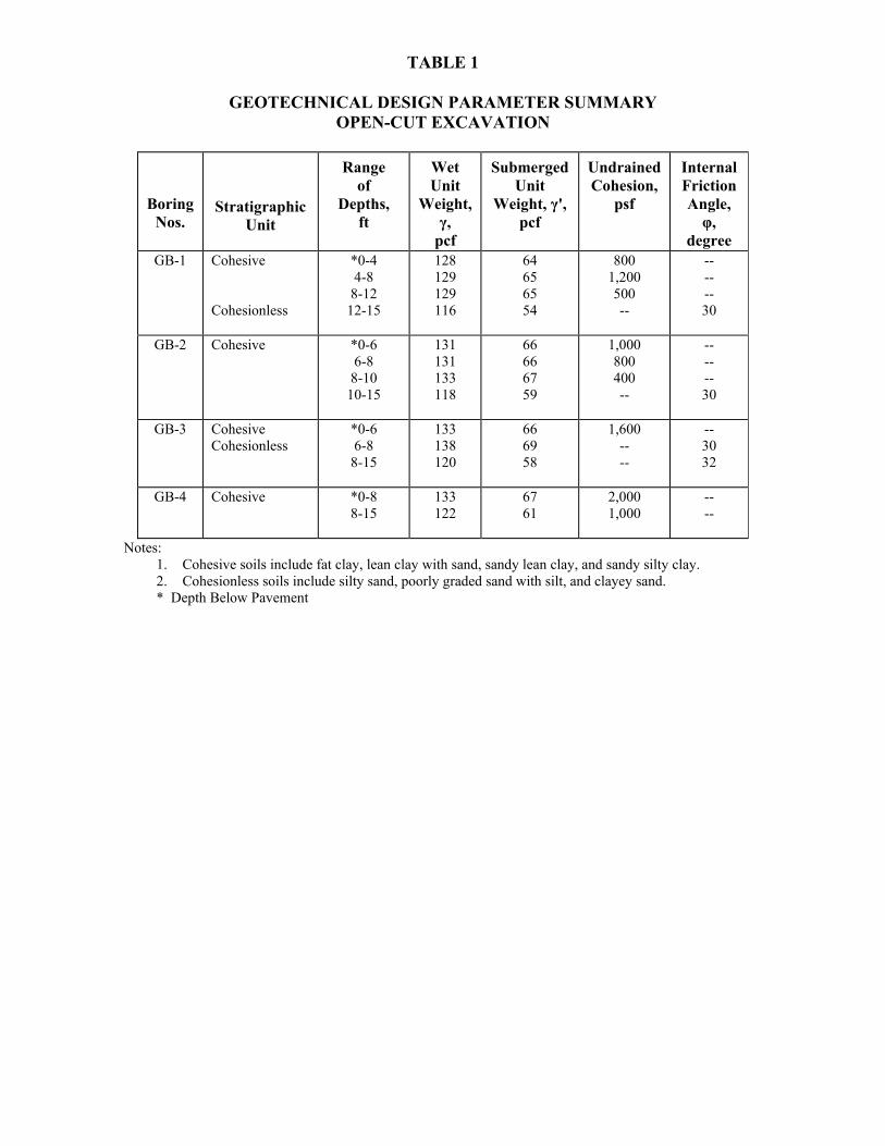
TABLE 1
GEOTECHNICAL DESIGN PARAMETER SUMMARY OPEN-CUT EXCAVATION
Boring
Nos.
Stratigraphic Unit
Range
of Depths,
ft
Wet Unit
Weight, γ,
pcf
Submerged Unit
Weight, γ', pcf
Undrained Cohesion,
psf
Internal Friction Angle,
φ, degree
GB-1 Cohesive Cohesionless
*0-4 4-8 8-12
12-15
128 129 129 116
64 65 65 54
800 1,200 500 --
-- -- -- 30
GB-2 Cohesive
*0-6 6-8 8-10
10-15
131 131 133 118
66 66 67 59
1,000 800 400 --
-- -- -- 30
GB-3 Cohesive Cohesionless
*0-6 6-8 8-15
133 138 120
66 69 58
1,600 -- --
-- 30 32
GB-4 Cohesive
*0-8 8-15
133 122
67 61
2,000 1,000
-- --
Notes: 1. Cohesive soils include fat clay, lean clay with sand, sandy lean clay, and sandy silty clay. 2. Cohesionless soils include silty sand, poorly graded sand with silt, and clayey sand. * Depth Below Pavement

APPENDIX A
Figure
Log of Borings ................................................................................................................ A-1 thru A-4
Symbols and Terms Used on Boring Logs .................................................................... A-5

APPENDIX B
Figure
Grain Size Distribution Curves ........................................................................................ B-1


![Bulletin 194R Fused and Non-Fused Disconnects...11 Bulletin 194R Fused and Non-Fused Disconnects Product Selection 4th Pole Modules Rated Current [A] Maximum Hp Ratings Fuse Dim. Ref](https://img.pdfslide.us/doc/110x75/5e3f37a7aa25636cac719ea2/bulletin-194r-fused-and-non-fused-disconnects-11-bulletin-194r-fused-and-non-fused.jpg)