Embed Size (px)
Citation preview
August 2014
Prepared for: Municipality of Anchorage
Project Management and Engineering P.O. Box 196650
Anchorage, Alaska 99519-6650
Prepared by: USKH Inc. now Stantec
2515 A Street Anchorage, Alaska 99503
Phone (907) 276-4245 Fax (907) 258-4653
USKH WO#1419006
FINAL
FAILURE INVESTIGATION
WESTCHESTER NORTH LAGOON BRIDGE
Anchorage, Alaska

This page intentionally left blank.
USKH Inc. now Stantec Failure Investigation – Final Report Westchester North Lagoon Bridge
August 2014
i
TABLE OF CONTENTS ACRONYMS .................................................................................................................................................... II
1 EXECUTIVE SUMMARY ......................................................................................................................... 12 INTRODUCTION.................................................................................................................................... 13 DESCRIPTION ....................................................................................................................................... 14 SITE OBSERVATIONS ............................................................................................................................ 55 ANALYSIS .............................................................................................................................................. 66 CONCLUSIONS .................................................................................................................................... 8
FIGURESFigure 1 – Vicinity and Location Map ...................................................................................................... 3Figure 2 – Bridge Elevation ......................................................................................................................... 4Figure 3 – Bridge Cross Section ................................................................................................................ 10
APPENDICESAppendix A – Original Construction DrawingsAppendix B – Calculations
USKH Inc. now Stantec Failure Investigation – Final Report Westchester North Lagoon Bridge
August 2014
ii
ACRONYMSAASHTO .............. American Association of State Highway and Transportation Officials DMV .................... Alaska Department of Motor Vehicles Glulam ................ glued laminated timber LRFD..................... Load and Resistance Factor Design MOA .................... Municipality of Anchorage NDS ...................... National Design Specification for Wood Construction PM&E ................... Project Management and Engineering Psf ........................ pounds per square foot UBC...................... Uniform Building Code USKH .................... USKH Inc. – Now Stantec
USKH Inc. now Stantec Failure Investigation – Final Report Westchester North Lagoon Bridge
August 2014
1
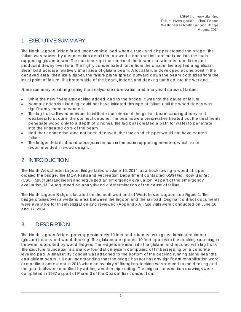
1 EXECUTIVE SUMMARY
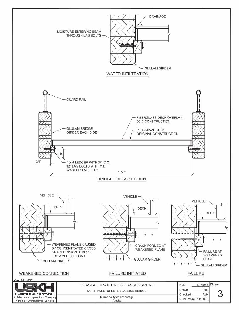
The North Lagoon Bridge failed under vehicle load when a truck and chipper crossed the bridge. The failure was caused by a connection detail that allowed a constant influx of moisture into the main supporting glulam beam. The moisture kept the interior of the beam in a saturated condition and produced decay over time. The highly concentrated force from the chipper tire applied a significant shear load across a relatively small area of glulam beam. A local failure developed at one point in the decayed area, then like a zipper, the failure plane spread outward down the beam both sides from the initial point of failure. This bottom side of the beam, ledger, and decking tumbled into the wetland.
Some summary points regarding the analysis site observation and analysis of cause of failure:
While the new fiberglass decking added load to the bridge, it was not the cause of failure. Normal pedestrian loading could not have initiated this type of failure until the wood decay was significantly more advanced. The lag bolts allowed moisture to infiltrate the interior of the glulam beam causing decay and weakness to occur in the connection zone. The beams were preservative treated but the treatments penetrate wood only to a depth of 2 inches. The lag bolts created a path for water to penetrate into the untreated core of the beam. Had that connection zone not been decayed, the truck and chipper would not have caused failure. The ledger detail induced cross-grain tension in the main supporting member, which is not recommended in wood design.
2 INTRODUCTION
The North Westchester Lagoon Bridge failed on June 16, 2014, as a truck towing a wood chipper crossed the bridge. The MOA Parks and Recreation Department contacted USKH Inc., now Stantec(USKH) Structural Engineers and requested an emergency evaluation. As part of the emergency evaluation, MOA requested an analysis and a determination of the cause of failure.
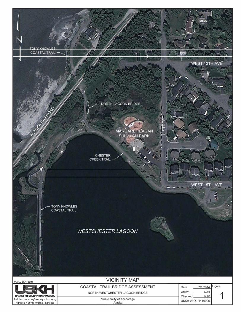
The North Lagoon Bridge is located on the northwest end of Westchester Lagoon, see Figure 1. The bridge crosses over a wetland area between the lagoon and the railroad. Original contract documents were available for this investigation and reviewed (Appendix A). Site visits were conducted on June 16 and 17, 2014.
3 DESCRIPTION
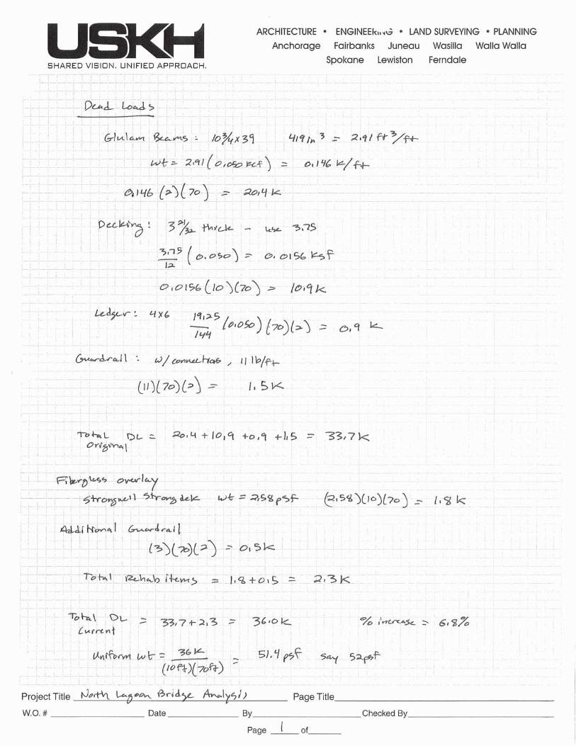
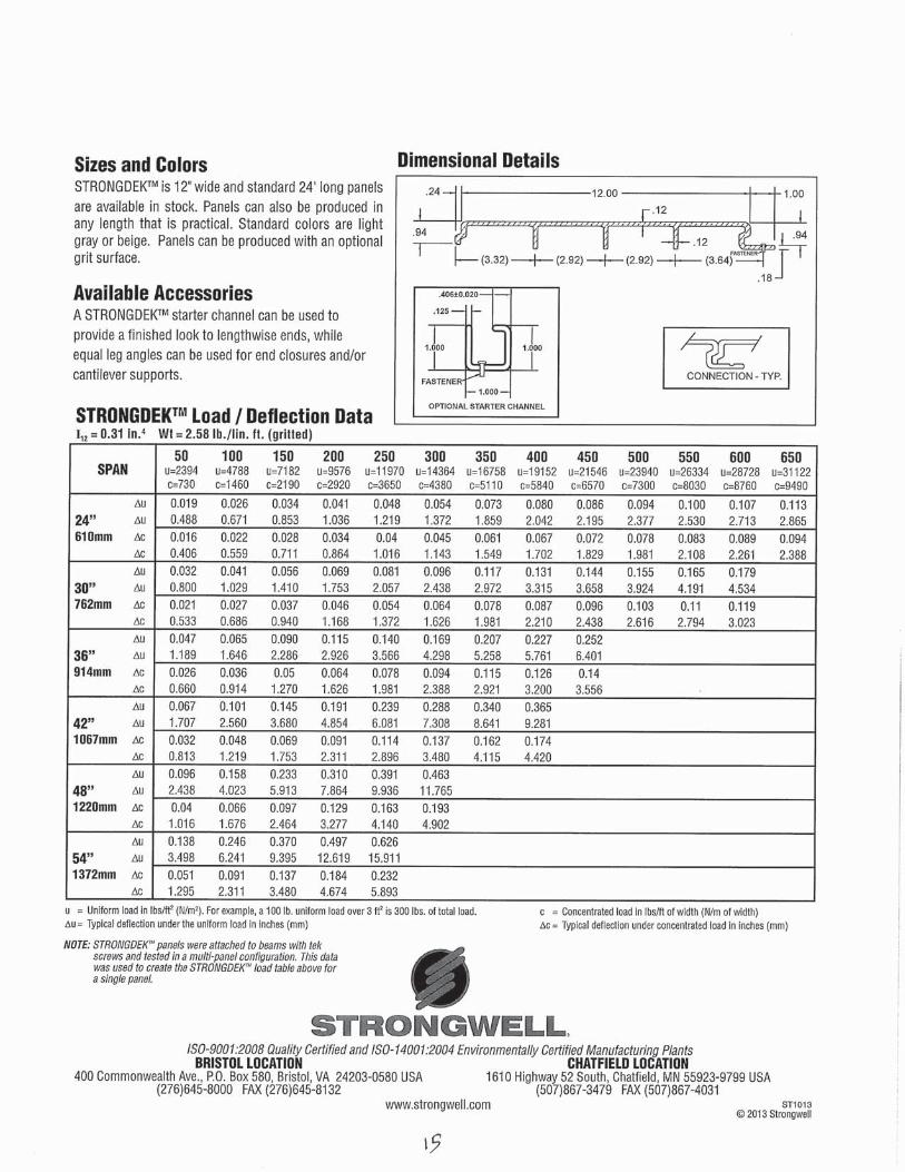
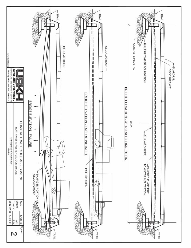
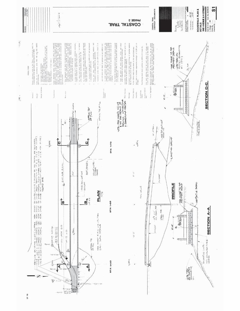
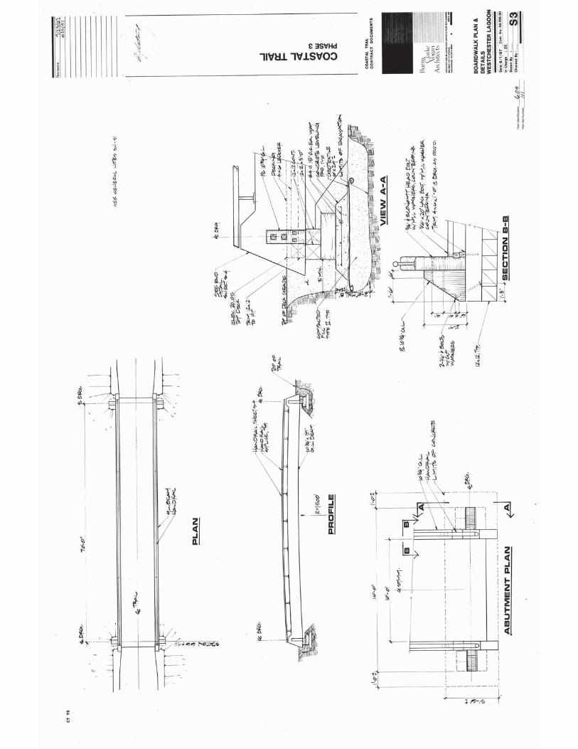
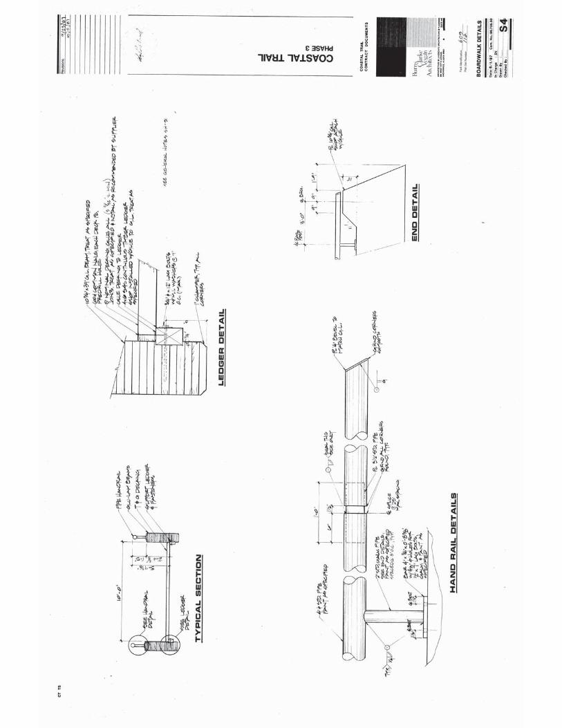
The North Lagoon Bridge spans approximately 70 feet and is framed with glued laminated timber (glulam) beams and wood decking. The glulams are spaced 10 feet apart with the decking spanning in between supported by wood ledgers. The ledgers are inset into the glulam, and secured with lag bolts. The structure foundation is a shallow foundation system composed of timbers resting on a concrete leveling pad. A small utility conduit was attached to the bottom of the decking running along near the east glulam beam. It is our understanding that the bridge has not has any significant rehabilitation work or modifications except in 2013 when an overlay of fiberglass decking was secured to the decking and the guardrails were modified by adding another pipe railing. The original construction drawings were completed in 1987 as part of Phase 3 of the Coastal Trail construction.
USKH Inc. now Stantec Failure Investigation – Final Report Westchester North Lagoon Bridge
August 2014
2
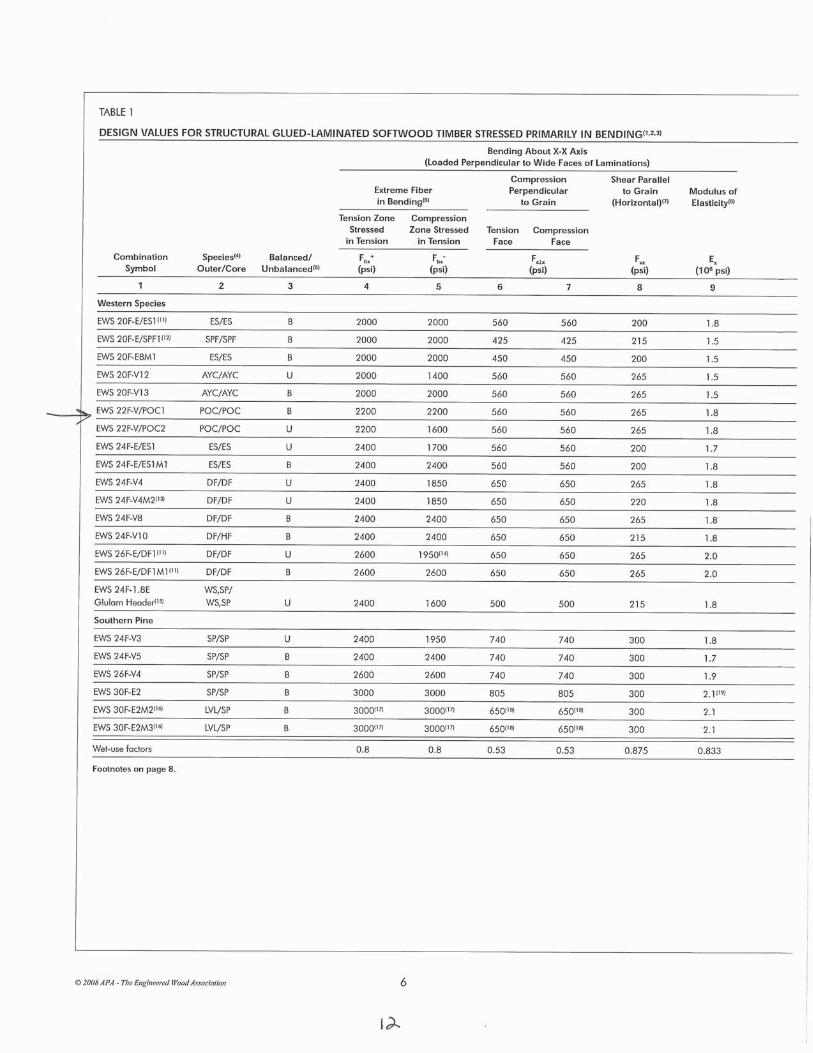
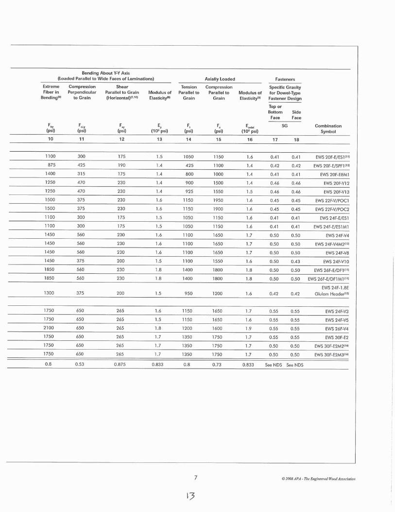
The original construction drawings have a general notes section that lists design criteria and material specifications, see Figure 2. The design codes cited are the 1985 UBC and 1983 AASTHO Specifications. Pertinent design loading indicated is 85 per square foot (psf) uniform live load and an overload vehicle with 10,000-pound (lb) weight and 8,000 lb axle load. The glulams specified are 22F-V8 DF/DF and other lumber Douglas Fir No. 1. All lumber was specified to be pressure treated.
USKH Inc. now Stantec Failure Investigation – Final Report Westchester North Lagoon Bridge
August 2014
5
4 SITE OBSERVATIONS
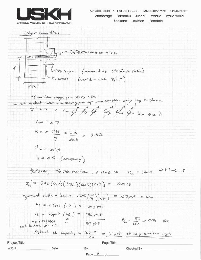
Site visits were conducted June 16 and June 17, 2014. The truck and chipper had been removed prior to the site visits and information regarding the equipment was supplied by the Municipality of Anchorage (MOA). The dimensions of the main bridge glulam beams, ledger, decking, and lag bolts were measured and compared to the construction document drawings. The glulam and lag bolts match the specific dimensions but the ledger connecting the decking to the glulam was slightly wider than called out. The called out ledger was a 4x6 which has actual dimensions of 3-1/2 by 5-1/2 inches. The measured depth matched the 5-1/2 inches but the measured width varies from 5 to 5-1/4 inches. The ledger inset dimension appeared to vary from 3/4- to 1-inch. This variation would not significantly change the capacity of this connection.
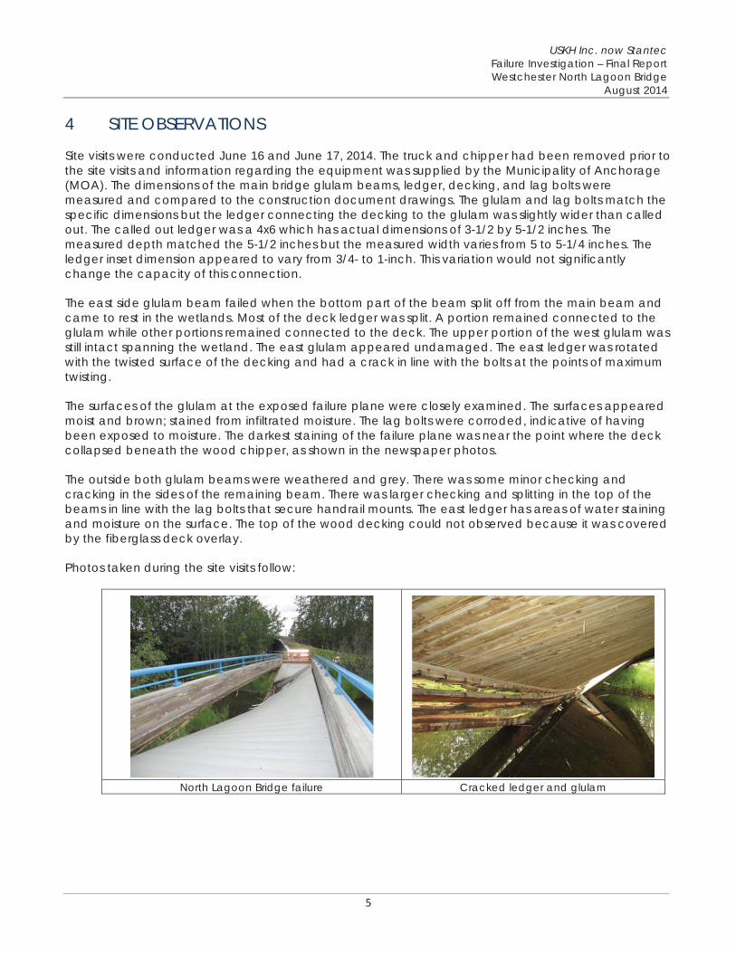
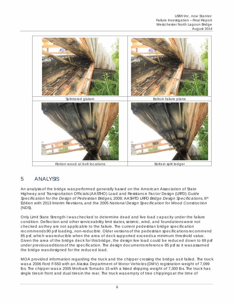
The east side glulam beam failed when the bottom part of the beam split off from the main beam and came to rest in the wetlands. Most of the deck ledger was split. A portion remained connected to the glulam while other portions remained connected to the deck. The upper portion of the west glulam was still intact spanning the wetland. The east glulam appeared undamaged. The east ledger was rotated with the twisted surface of the decking and had a crack in line with the bolts at the points of maximum twisting.
The surfaces of the glulam at the exposed failure plane were closely examined. The surfaces appeared moist and brown; stained from infiltrated moisture. The lag bolts were corroded, indicative of having been exposed to moisture. The darkest staining of the failure plane was near the point where the deck collapsed beneath the wood chipper, as shown in the newspaper photos.
The outside both glulam beams were weathered and grey. There was some minor checking and cracking in the sides of the remaining beam. There was larger checking and splitting in the top of the beams in line with the lag bolts that secure handrail mounts. The east ledger has areas of water staining and moisture on the surface. The top of the wood decking could not observed because it was covered by the fiberglass deck overlay.
Photos taken during the site visits follow:
North Lagoon Bridge failure Cracked ledger and glulam
USKH Inc. now Stantec Failure Investigation – Final Report Westchester North Lagoon Bridge
August 2014
6
Splintered glulam Bolts in failure plane
1
Rotten wood at bolt locations Bolts in split ledger
5 ANALYSIS
An analysis of the bridge was performed generally based on the American Association of State Highway and Transportation Officials (AASTHO) Load and Resistance Factor Design (LRFD) Guide Specification for the Design of Pedestrian Bridges, 2009; AASHTO LRFD Bridge Design Specifications, 6th
Edition with 2013 Interim Revisions, and the 2005 National Design Specification for Wood Construction(NDS).
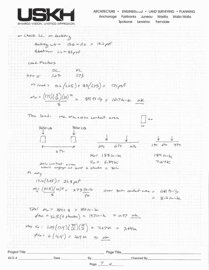
Only Limit State Strength I was checked to determine dead and live load capacity under the failure condition. Deflection and other serviceability limit states, seismic, wind, and foundations were not checked as they are not applicable to the failure. The current pedestrian bridge specification recommends 90 psf loading, non-reducible. Older versions of the pedestrian specifications recommend 85 psf, which was reducible when the area of deck supported exceeds a minimum threshold value. Given the area of the bridge deck for this bridge, the design live load could be reduced down to 69 psf under previous editions of the specification. The design documents reference 85 psf so it was assumed the bridge was designed for the reduced load.
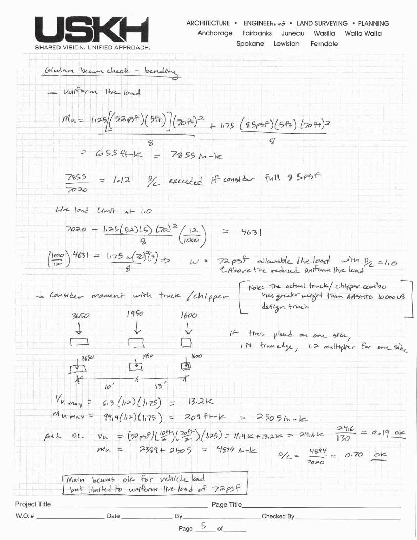
MOA provided information regarding the truck and the chipper crossing the bridge as it failed. The truck was a 2006 Ford F-550 with an Alaska Department of Motor Vehicles (DMV) registration weight of 7,099 lbs. The chipper was a 2005 Morbark Tornado 15 with a listed shipping weight of 7,300 lbs. The truck has single tires in front and dual tires in the rear. The truck was empty of tree chippings at the time of
USKH Inc. now Stantec Failure Investigation – Final Report Westchester North Lagoon Bridge
August 2014
7
crossing. The chipper has a single axle with single tires on each side. The truck appeared custom with a cargo section on the rear so an estimation of front-rear distribution of load and wheelbase of the truck was made by reviewing manufacturer specifications regarding the type of truck. The chipper was assumed to apply little tongue weight to the truck, so the weight of the chipper was fully applied to the single axle.
The new handrail and fiberglass deck overlay added in the 2013 trail rehabilitation added approximately 7% weight to the bridge. Modifications made to structures that cause a load increase of less than 10% are usually not considered significant.
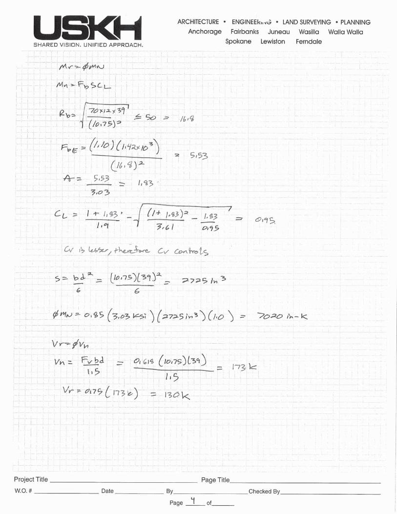
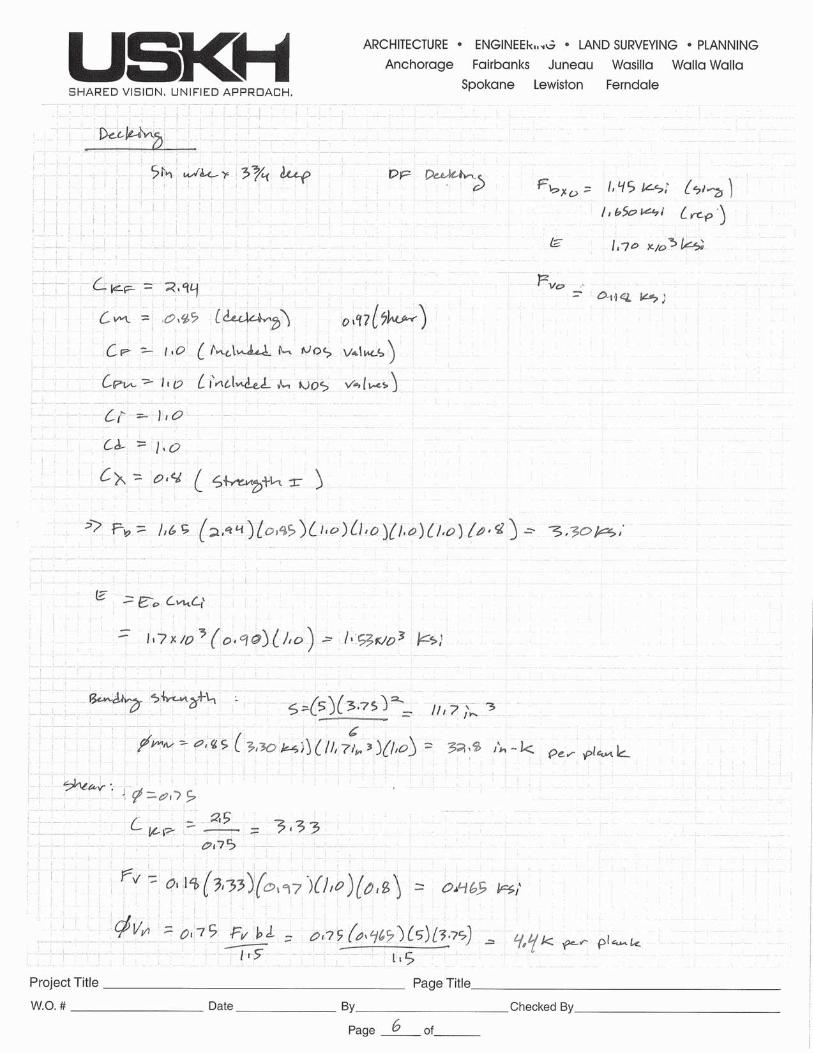
Wood member allowable stresses were taken from the current AASHTO or NDS provisions based on the grades of wood noted in the general notes on the original construction documents.
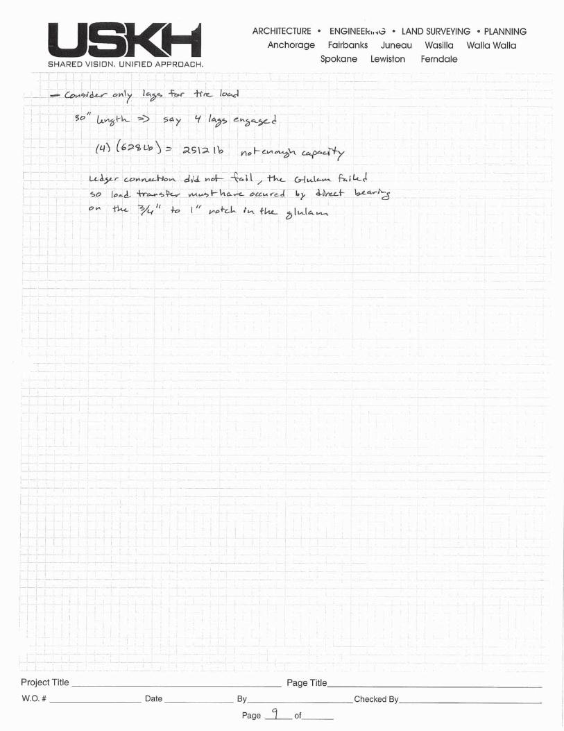
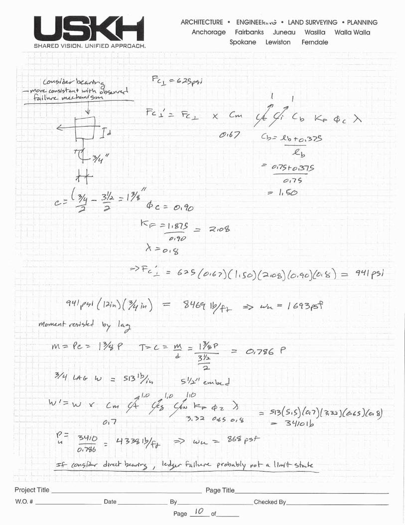
The analysis shows the capacity of the main glulam beams is limited by an overall uniform live load of approximately 72 psf. The main beams have adequate capacity for the design vehicle and actual truck plus chipper vehicle loading. The decking is limited by the point loading from vehicles. It is loaded to its maximum capacity by the vehicle that crossed the bridge. The ledger connection appears to have adequate capacity for both uniform load and concentrated vehicle load assuming a bearing limit state on the notched glulam. Full calculations are included in Appendix B.
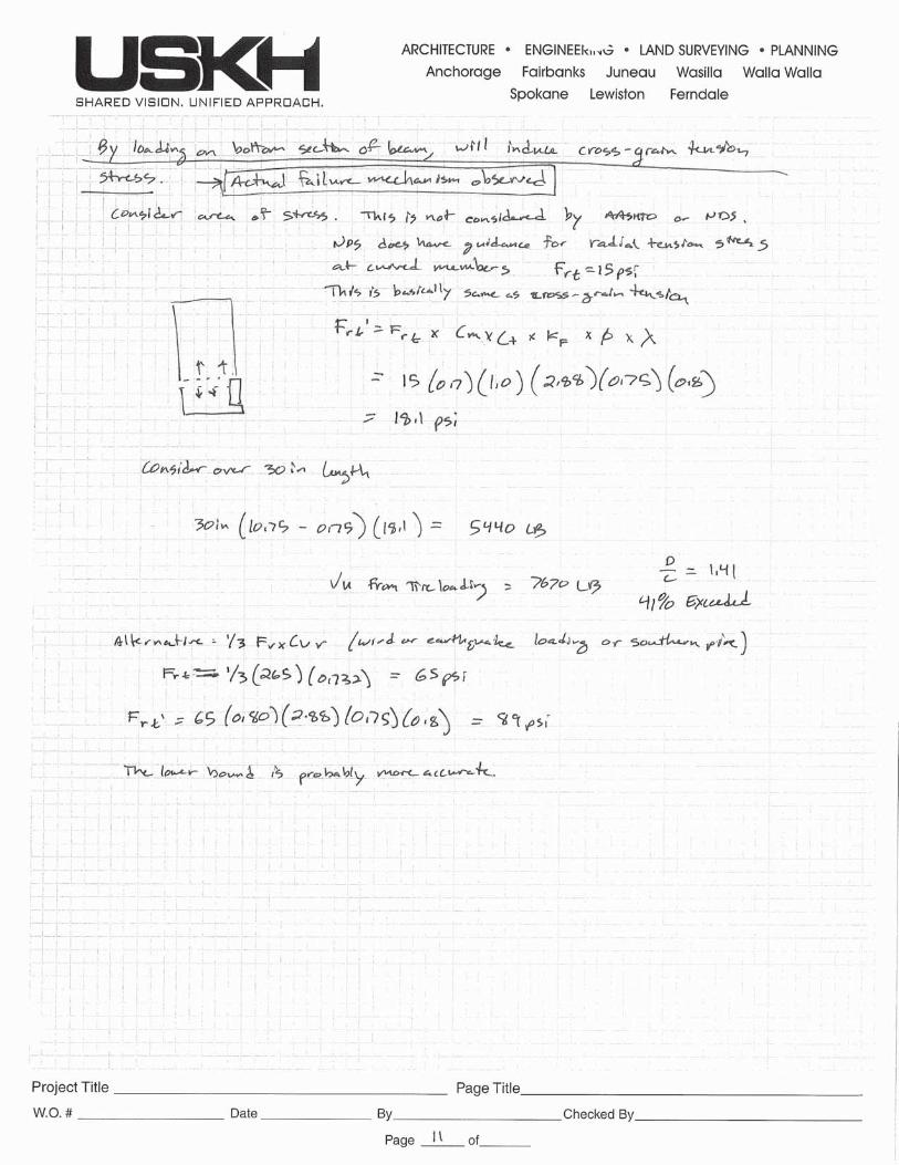
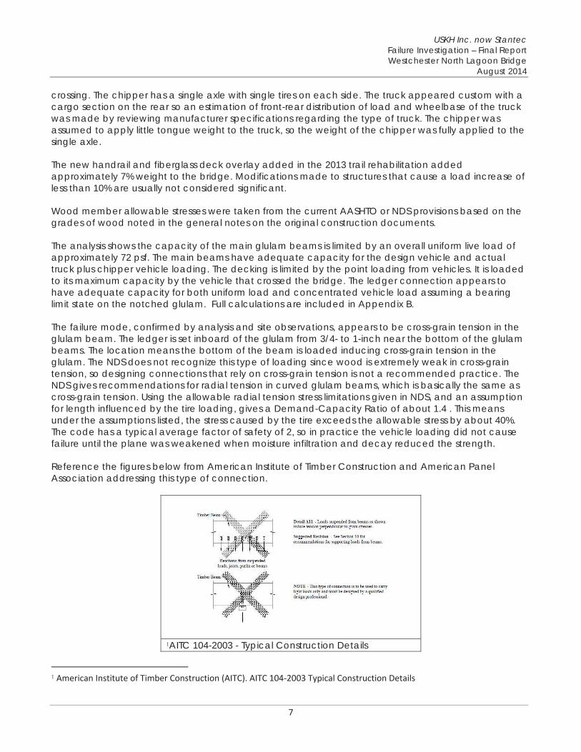
The failure mode, confirmed by analysis and site observations, appears to be cross-grain tension in the glulam beam. The ledger is set inboard of the glulam from 3/4- to 1-inch near the bottom of the glulam beams. The location means the bottom of the beam is loaded inducing cross-grain tension in the glulam. The NDS does not recognize this type of loading since wood is extremely weak in cross-grain tension, so designing connections that rely on cross-grain tension is not a recommended practice. The NDS gives recommendations for radial tension in curved glulam beams, which is basically the same as cross-grain tension. Using the allowable radial tension stress limitations given in NDS, and an assumption for length influenced by the tire loading, gives a Demand-Capacity Ratio of about 1.4 . This means under the assumptions listed, the stress caused by the tire exceeds the allowable stress by about 40%. The code has a typical average factor of safety of 2, so in practice the vehicle loading did not cause failure until the plane was weakened when moisture infiltration and decay reduced the strength.
Reference the figures below from American Institute of Timber Construction and American Panel Association addressing this type of connection.
1AITC 104-2003 - Typical Construction Details
1 American Institute of Timber Construction (AITC). AITC 104 2003 Typical Construction Details
USKH Inc. now Stantec Failure Investigation – Final Report Westchester North Lagoon Bridge
August 2014
8
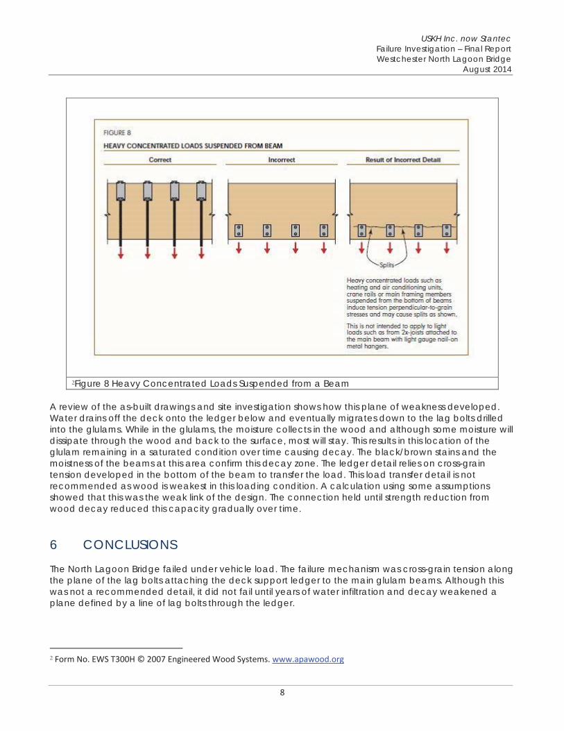
2Figure 8 Heavy Concentrated Loads Suspended from a Beam
A review of the as-built drawings and site investigation shows how this plane of weakness developed. Water drains off the deck onto the ledger below and eventually migrates down to the lag bolts drilled into the glulams. While in the glulams, the moisture collects in the wood and although some moisture will dissipate through the wood and back to the surface, most will stay. This results in this location of the glulam remaining in a saturated condition over time causing decay. The black/brown stains and the moistness of the beams at this area confirm this decay zone. The ledger detail relies on cross-grain tension developed in the bottom of the beam to transfer the load. This load transfer detail is not recommended as wood is weakest in this loading condition. A calculation using some assumptions showed that this was the weak link of the design. The connection held until strength reduction from wood decay reduced this capacity gradually over time.
6 CONCLUSIONS
The North Lagoon Bridge failed under vehicle load. The failure mechanism was cross-grain tension along the plane of the lag bolts attaching the deck support ledger to the main glulam beams. Although this was not a recommended detail, it did not fail until years of water infiltration and decay weakened a plane defined by a line of lag bolts through the ledger.
2 Form No. EWS T300H © 2007 Engineered Wood Systems. www.apawood.org
USKH Inc. now Stantec Failure Investigation – Final Report Westchester North Lagoon Bridge
August 2014
9
Water draining off the deck onto the ledger below and eventually migrated down the lag bolts drilled into the glulams. The constant influx of moisture into the glulam beam kept the plane in a saturated condition and decayed over time. The ledger detail relied on cross-grain tension developed in the bottom of the beam to transfer the load. The highly concentrated force from the chipper tire applied a significant shear load across a relatively small area of glulam beam. A local failure developed at one point, then like a zipper, the failure plane spread outward down the beam both sides from the initial point of failure. This bottom side of the beam, ledger, and decking tumbled into the wetland.
Some summary points regarding the analysis site observation and analysis of cause of failure:
While the new fiberglass decking added load to the bridge, it was not the cause of failure. Normal pedestrian loading could not have initiated this type of failure until the wood decay was significantly more advanced. The lag bolts allowed moisture to infiltrate the interior of the glulam beam causing decay and weakness to occur in the connection zone. The beams were preservative treated but the treatments penetrate wood only to a depth of 2 inches. The lag bolts created a path for water to penetrate into the untreated core of the beam. Had that connection zone not been decayed, the truck and chipper would not have caused failure. The ledger detail induced cross-grain tension in the main supporting member, which is not recommended in wood design.
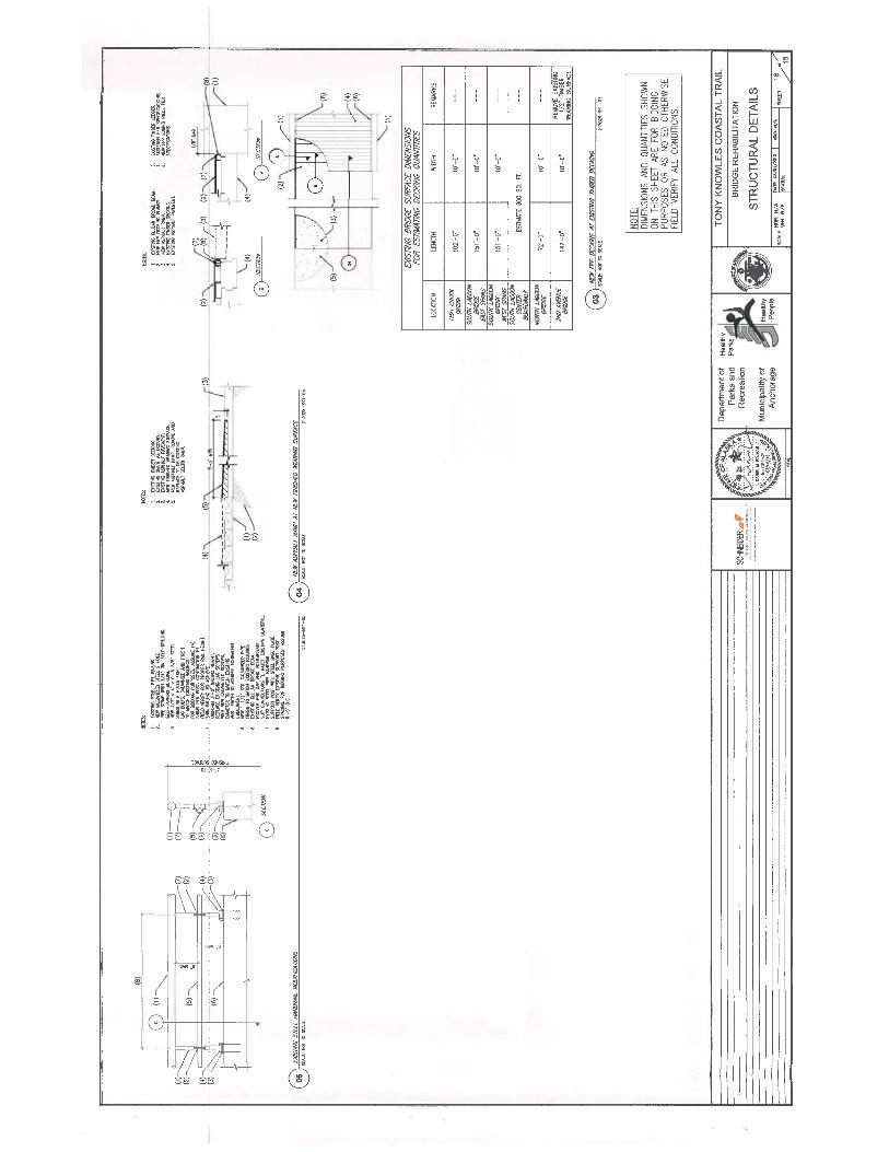
Appendix A – Original Construction Drawings
Appendix B – Calculations