Embed Size (px)
Citation preview

Final Design Report
Final Design Report (FDR)
MarsOz Habitat Garage
MarsOz Garage Group
2015
Version 0.08
Final Design Report
i
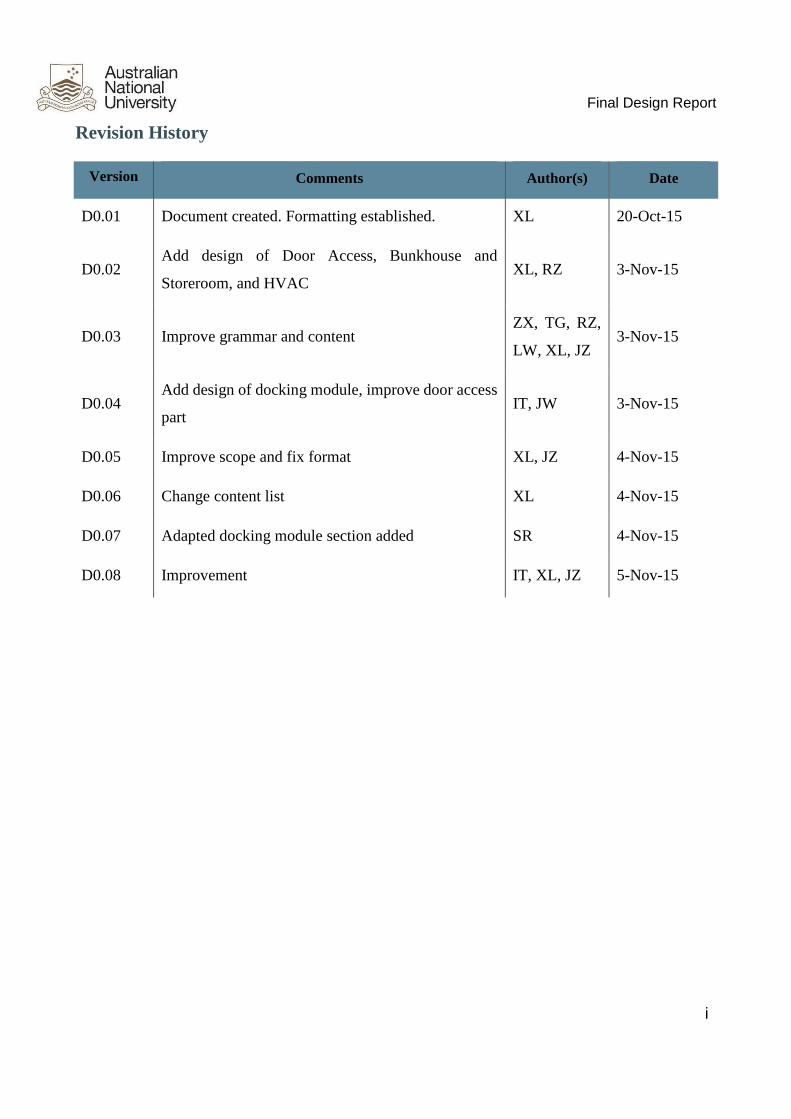
Revision History
Version Comments Author(s) Date
D0.01 Document created. Formatting established. XL 20-Oct-15
D0.02 Add design of Door Access, Bunkhouse and
Storeroom, and HVAC XL, RZ 3-Nov-15
D0.03 Improve grammar and content ZX, TG, RZ,
LW, XL, JZ 3-Nov-15
D0.04 Add design of docking module, improve door access
part IT, JW 3-Nov-15
D0.05 Improve scope and fix format XL, JZ 4-Nov-15
D0.06 Change content list XL 4-Nov-15
D0.07 Adapted docking module section added SR 4-Nov-15
D0.08 Improvement IT, XL, JZ 5-Nov-15

Final Design Report
ii
Author details
Client details
Initials / Name: E-mail: Phone:
JC Jonathan Clarke [email protected] 0418 401 612
Initials / Name: E-mail: Phone:
JZ Jiayi Zhang [email protected] 0405 626 376
RZ Rui Zhai [email protected] 0414 986 171
SY Shun Yao [email protected] 0405 704 350
LW Liyuan Wang [email protected] 0451 300 301
JL Junxu Lu [email protected] 0424 383 171
ZX Zhenting Xu [email protected] 0449 724 620
JY Jiangyue Wang [email protected] 0413 157 180
CG Chujun Guan [email protected] 0404 945 372
BF Bingfei Fu [email protected] 0415 514 459
TG Tianyang Gao [email protected] 0449 866 427
YS Yifei Shen [email protected] 0405 636 203
XL Xuran Li [email protected] 0449 501 230
IE Isaac Evans [email protected] 0424 047 611
IT Ian Thai [email protected] 0466 381 818
SR Stephen Rixon [email protected] 0400 800 503

Final Design Report
iii
Executive Summary
The MarsOz garage project focuses on the design of multiple function garage in MARS. This also
covers the docking module which serves as a connection and walkway between the habitat module
and garage.
The final design report begins by introducing the context of the project. Before illustrating the final
design of the team, the team restates the requirements and attributes from the SRS and SDS
deliverables.
The description of the detailed design covers four subsystems, involving garage door access,
bunkhouse/storeroom, HVAC, and docking module. There is a verification strategy for the
components of every subsystem. There is a budget summary which lists the cost of every section.
Finally the risks for the project and relative solutions are discussed in risk analysis.
The team goal was to achieve an easily implemented, cheap design with reliable quality and light
weight.

Final Design Report
iv
Contents
Executive Summary ............................................................................................................. iii
List of Figures ..................................................................................................................... vi
List of Tables ..................................................................................................................... vii
Acronyms and Abbreviations ............................................................................................... vii
Units of Measurement .......................................................................................................... ix
1 Introduction ................................................................................................................. 1
1.1 Project Mission Statement ....................................................................................... 1
1.2 Document Purpose ................................................................................................. 1
1.3 Current Progress. .................................................................................................... 2
2 Scope .......................................................................................................................... 3
3 System Requirements and Attributes ............................................................................... 4
4 Final Design ................................................................................................................. 7
4.1 Bunkhouse and Storeroom ...................................................................................... 7
4.1.1 Bunkhouse .............................................................................................................. 7
4.1.1 Storage Layer ........................................................................................................ 11
4.1.3 Verification ........................................................................................................... 18
4.2 HVAC ................................................................................................................ 19
4.2.1 Heating & cooling (air conditioning) ....................................................................... 19
4.2.2 Air conditioner ...................................................................................................... 20
4.2.2 Ventilation ............................................................................................................ 23
4.3 Door Access ........................................................................................................ 27
4.3.1 Operation and dimension description ....................................................................... 27
4.3.2 Features of our design ............................................................................................ 30
4.3.3 Materials and models ............................................................................................. 31
4.3.4 Ramp Design......................................................................................................... 33
4.3.5 Interact with other systems ..................................................................................... 36
4.3.6 Future Consideration .............................................................................................. 36
4.3.7 Verification ........................................................................................................... 37
4.4 Docking Module .................................................................................................. 38
4.4.1 Main Compartment ................................................................................................ 38
4.4.1.1 Design Description .............................................................................................. 38

Final Design Report
v
4.4.1.2 Cost Summary .................................................................................................... 40
4.4.1.3 Fastening Assemblies Used in the Docking Module ................................................ 41
4.4.1.4 Docking to Main Modules Interface ...................................................................... 42
4.4.1.5 Main Compartment Floor ..................................................................................... 45
4.4.1.6 Support Beams and Legs ...................................................................................... 48
4.4.1.7 Side Beams and Face Plates ................................................................................. 51
4.4.1.8 Canopy .............................................................................................................. 51
4.4.2 Flexible Extension Section ...................................................................................... 52
4.4.2.1 Outer layer ......................................................................................................... 52
4.4.2.2 Tunnel ............................................................................................................... 52
4.4.2.3 Prop Shaft .......................................................................................................... 53
4.4.2.4 The material used in flexible section: .................................................................... 54
4.4.3 Docking Module Hatch .......................................................................................... 55
4.4.3.1 Detailed Door Design .......................................................................................... 57
4.4.3.2 Material & Budget .............................................................................................. 57
4.4.4 Verification ........................................................................................................... 57
5 Budget Summary ........................................................................................................ 59
6 Risk analysis .............................................................................................................. 61
7 References ................................................................................................................. 67
8 Appendix ................................................................................................................... 70
8.1 Project Team and Team Structure............................................................................... 70
8.2 Trade off Analysis (House of Quality) ........................................................................ 71
8.3 System Cascade ....................................................................................................... 73
8.4 Arkaroola information .............................................................................................. 83
8.5 Past work diagram .................................................................................................... 85
8.5 Price of paint ........................................................................................................... 85
Final Design Report
vi
List of Figures
Figure 4.1.1 Dimension of the garage
Figure 4.1.2 Overall internal design for bunkhouse
Figure 4.1.3 Joint connection overview
Figure 4.1.4 Joint connection and bed
Figure 4.1.5 Design of the storage space under the floor
Figure 4.1.6 (left): Design of the storage area
Figure 4.1.7 (right): Blue area will be the supporting area that endure the weight of human
Figure 4.1.8 Dimension of each individual store box in mm
Figure 4.1.9 Metal grid flooring panels
Figure 4.1.10 Plan view of the spandrel girder for one side of the room
Figure 4.1.11 Side view of the spandrel girder
Figure 4.1.12 Front view of the spandrel girder
Figure 4.2.1 basic operation process of air conditioner
Figure 4.2.2 Room size and power required
Figure 4.2.3 Premium 3.5kW Reverse Cycle Split System: LG-P12AWN-14
Figure 4.2.4 Sand filter
Figure 4.3.0 Main garage door (solidworks drawing)
Figure 4.3.1 Main garage door
Figure 4.3.2 Main door fully open
Figure 4.3.3 Main door close
Figure 4.3.4 Ramp
Figure 4.3.5 6061 Aluminium Alloy
Figure 4.3.6 PowerTools K5000-P electric capstan
Figure 4.3.7: 7x19 Stainless cable with diameter 5mm
Figure 4.3.8: YH-QC301 Synthetic rubber sealing strips
Figure 4.3.9 Operating process of the main garage door
Figure 4.3.10 Single direction gear
Figure 4.3.11 Electromagnet
Figure 4.3.12 The Force Body Diagram (FBD) for the rover
Figure 8.1 Team structure

Final Design Report
vii
Figure 8.2: House of Quality
Figure 8.3 Arkaroola annual temperatures & rainfall
Figure 8.4 Arkaroola temperature record
Figure 8.5 Past design diagram
Figure 8.6.1 docking module material 1
Figure 8.6.2 docking module material 2
Figure 8.6.3 docking module material 3
Figure 8.6.4 docking module material 4
List of Tables
Table 3.1: Requirements and attributes
Table 4.1 Verification of bunkhouse and Storeroom
Table 4.2.1 AC technical specification
Table 4.2.2 Cost estimate
Table 4.2.3 Choices of exhaust fan for ventilation
Table 4.2.4 Verification of HVAC
Table 4.3.1 Total price of the door design
Table 4.3.2 Verification of the doorway access design
Table 5.1 Budget summary
Table 6.1 team management risk
Table 6.2 Design Risk
Table 8.3 System cascade showing two levels of qualitative attributes
Table 8.5 Price of paint
Acronyms and Abbreviations
SRS - System Requirement Specification
AS - Australian Standard
NZS – New Zealand Standard
IEC – International Electro technical Commission
ISO – International Organization of Standardization
MARS – Mars Analogue Research Station

Final Design Report
viii
MSA - Mars Society Australia
HAB – Habitat Module
FBD – Functional Block Diagram
FFBD – Function Flow Block Diagram
GAD – Garage door
GAR – Garage
BHS – Bunkhouse system
HVAC – Heating Ventilation Air-Conditioning system
AC – Air-conditioner
EER - energy efficiency ratio
DOS – Docking system
ROV – Rover
TOS – Towing system
ENV – Environment
USER – User

Final Design Report
ix
Units of Measurement
The International System of Units (SI) is used in this project unless otherwise specified.
Table A: Units of Measurement
Measurement Symbol Description
Area m2 Square metres
Volume m3 Cubic metres
Volume gallon Gallon
Pressure Pa Pascal
Power W Watts
Energy kW h Kilowatt hour
Energy J Joules
Time s Seconds
Currency $ Australian dollar
Temperature °C Degrees Celsius
Luminous intensity cd Candela
Force N Newton
Air Flow Rate L/sec Litres per second
Final Design Report
1
1 Introduction
1.1 Project Mission Statement
Mars Society Australia (MSA) proposes to build an analogue research station in Arkaroola, South
Australia for the simulation of a Mars mission and environment. In this project, the main purpose is
to design the interior layout of the garage so that it should provide accommodation for 12 people, or
should be used as a storage room when the rover is out of the field. In the meantime, the design of
the main garage door and the connection between the main habitat and the garage, named docking
module are included in this project.
As for the requirements, the garage must be strong enough to hold the 4-ton rover and there shall be
enough space for the accommodation of 12 people. The conversion time between garage,
accommodation and storage room shall be no more than 8 hours, according to the client. For the main
garage door, it should be able to hold the 4-ton rover, with an additional smaller door for human
access available as well. For the docking module, it shall connect the main habitat with the garage
design, and shall allow passage between modules, holding the weight of maximum 2 people.
Considering the requirements from the client, the team has developed the following high-level
customer needs.
● The garage shall be able to contain the 4-ton rover, both in space and load-bearing abilities
● The garage shall be able to convert into a bunkhouse or a storage room.
● When the rover is in the field, the garage shall be able to provide enough space for the
accommodation of 12 people.
● The interior environment in the garage shall be comfortable for human living.
● The garage shall be connected to the main habitat.
● The garage shall have power access.
1.2 Document Purpose
The purpose of this document is to demonstrate the final design and prototype of the garage for MarsOz Habitat.
Final Design Report (FDR) is the finalized document that to be submitted to the client Dr. Jonathan
Clarke from the MSA. The document includes the detailed design of the garage done by
the team, and verification of requirements outlined in the System Design Specification (SDS)
document.

Final Design Report
2
The team has divided the garage into independent subsystems. In this report, detailed design will be
discussed in different subsystem sections. Each of the subsystem section will contain the following
information:
● Overview of the design
● The strategic scheme of the design
● Requirements specifications and verifications
● Detailed design to meet the requirements
● Budget estimation
1.3 Current Progress.
The purpose of this document (FDR) is to provide a finalized detailed design of the garage in terms
of all subsystems. Considering the milestone the team developed in the PMP-B, this is the sign that
the Final Design Approval period ends. Submitting this report to the client will let the team approach
to closure of the project. Based on the feedback from the client, the team could analyse the
performance of all the team member as individual and as a team. After the analysis, this project will
be officially closed.
Final Design Report
3
2 Scope
As mentioned in previous sections, the aim of this project is to provide an appropriate design for the
garage of MarsOz Habitat. This document includes the final design of a completed system design of
the garage, and make convincible discussion and analysis about how the design shall meet all
requirements and attributes in our System Design Specification document (SDS), provide justification
of chosen design concepts and optimisation of performance and cost reduction.
The system design is divided into four sub-systems and this documents is divided to reflect the four
major subsystems. This division was done at the beginning of the conceptual design process and is
applied until now. The four groups take charge of the design of door access; bunkhouse & storeroom;
heating, ventilation and air-conditioning (HVAC); and docking module. The division is according to
the mutually independent subsystems of the system design, which are door access, internal design
(bunkhouse, storeroom, and HVAC system), and docking module. The 3 subsystems have been well
defined in previous document. In general, this FDR document will deliver the detailed design for
these 4 parts, and make them integrated as a completed garage system.
The design process was based on official document, such as the document AAS 06-267 (Willson,
Clarke & Murphy, 2005), which is a very useful document for the team to determine the specifications
of requirements. We also quote the parameters from previous ENGN4221 works, such as the Final
Design Report in 2012 MarsOz group (shown in reference). Each group of the team shall provide a
cost estimation for its subsystem design. The costs accounting for products and materials in all groups
are according to the price situation in current Australia or international market.
Be aware that because of the budget limit the team cannot provide any physical model or prototype
to mimic the performance of the system design. However, the team applies useful tools such as
ANSYS and Solidworks to produce a precise design sketch and simulate the performance, for
example, force analysis, of the system design. With the simulation of the software the team shall show
that the design for the garage should be able to finish the tasks justified in the document. However,
the team should admit that the simulation cannot perfectly indicate the deployment of the design in
reality. Therefore the document also gives risk analysis of the design and designing process.
Through the process of the project, the team conducted effective communication with the programme
manager Dr. Liam Waldron and project client Dr. Jonathan Clarke. Their feedback had a great help
for the team’s progress, especially for the preliminary design review and final design report.

Final Design Report
4
Hopefully the design from the ENGN4221 MarsOz Habitat project can make useful suggestion or
even part of the design to the Australian Mars Analogue Research Station in Arkaroola.
3 System Requirements and Attributes
Before illustrating the final design, there is a review of system requirements and attributes. The final
design is based on these system requirements which have already been accepted by the client.
The table below is the instruments of the system requirements and attributes table. Not all of the
attributes have target values, for example, budget, the client claimed that the budget should be as low
as possible. So there is no target value of the budget currently.
+ Maximize the target value for the corresponding technical attribute.
- Minimize the target value for the corresponding technical attribute.
o Optimize the target value for the corresponding technical attribute. Used when the
suitable range of target value is not fully known, such that optimization process can be
initiated to identify the suitable target value for the technical attribute.

Final Design Report
5
R.I.D. Engineering
Requirement
Metric D.O.I Target Value Dep. on Req. by V.I.D
R1.0 Garage
R1.1 Volume Volume (m3) o 62.58m3 R2, R3, R4 V1.0
R1.2 Doorway access Length (m)
Power consumption (W)
o 3.181 x 3.181m
100W
R1.1 R8.1
R8.2
V1.0
R1.3 Weight Load bearing(kg) + 8000kg V1.0
R2.0 Bunkhouse
R2.1 Containing 12 people Volume (m3) + m3 R1.1 R8.2 V2.0
R2.2 Living equipment N/A o N/A R1.1 R8.2 V2.0
R2.3 Bedding Load bearing(kg) o 150 R8.2 V2.0
R3.0 Storeroom Volume (m3) + 62.58m3 R1.1 V3.0
R4.0 Comfort (HVAC)
R4.1 Air Conditioning Temperature(C)
Humidity (kg/m3)
o 26°C R7.0 R4.2
R8.1 R8.2
V4.0
R4.2 Ventilation Airflow rate(m3/h) o 385 m3/h R7.0 R4.1 R8.1 R8.2 V4.0
R4.2 Ventilation Airflow rate(m3/h) o 385 m3/h R7.0 R4.1 R8.1 R8.2 V4.0
R5.0 Conversion
R5.1 Conversion time Time (hours) - Less than 8 hours R1.1 V5.0
R6.0 Docking module
R6.1 Passage Length (m) + 2.8m R1.1 V6.0
R6.2 Passage Weight capacity (kg) 200kg R8.2 V6.0
R7.0 Power transmission Energy (kWh) + 64.5 kW h R4.0 R5.0 V7.0
R8.0 Safety
R8.1 Rover Protection
R8.2 Liveable conditions Temperature, ventilation,
lighting, humidity
o N/A R2.0 R4.0 V8.0
Final Design Report
6
R.I.D. Engineering
Requirement
Metric D.O.I Target Value Dep. on Req. by V.I.D
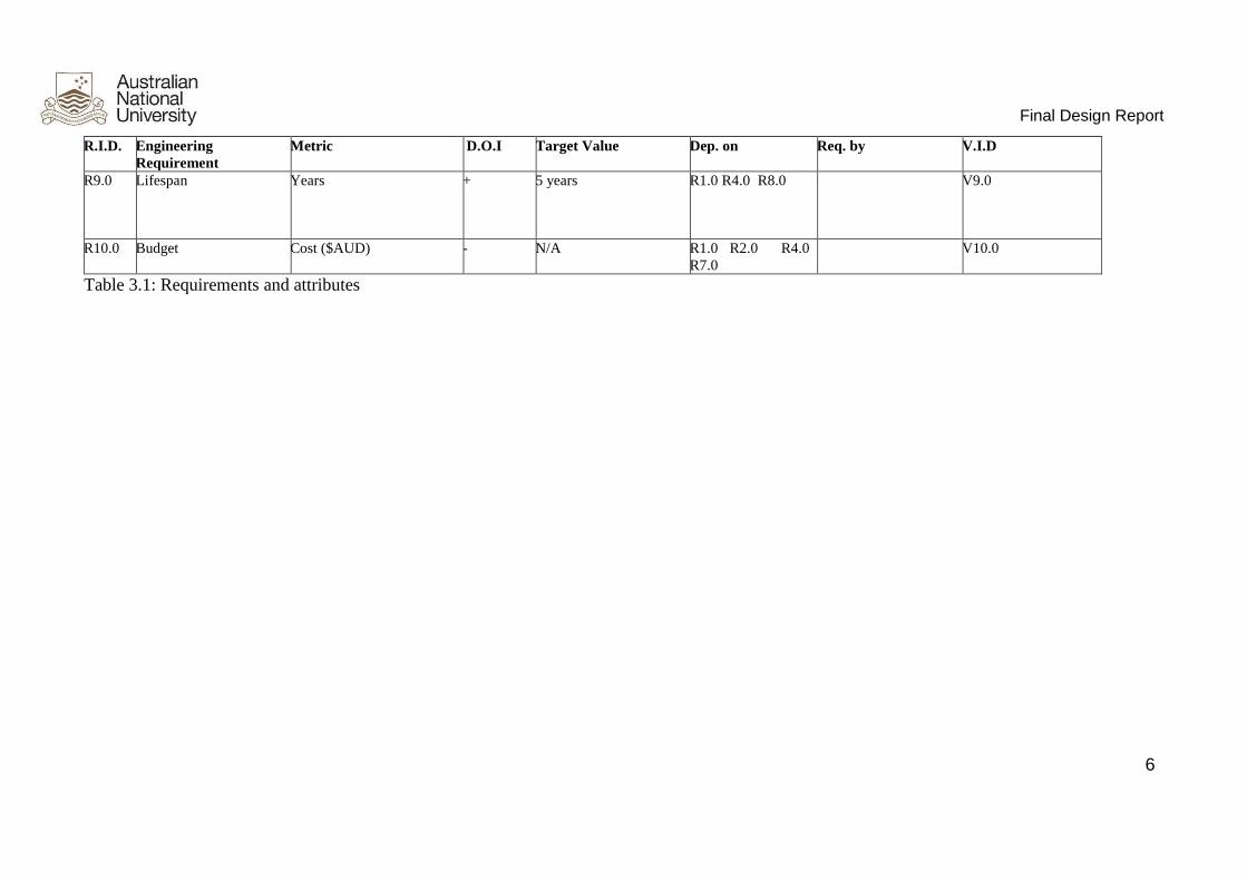
R9.0 Lifespan Years + 5 years R1.0 R4.0 R8.0 V9.0
R10.0 Budget Cost ($AUD) - N/A R1.0 R2.0 R4.0
R7.0
V10.0
Table 3.1: Requirements and attributes

Final Design Report
7
4 Final Design
4.1 Bunkhouse and Storeroom
4.1.1 Bunkhouse
One of customer requirements for Mars garage is to convert from garage functioning to a bunkhouse
that should be able to contain maximum of 12 people. The team plans to apply folding beds for 12
people living in the garage. The design process aims to provide the personnel a relatively comfortable
environment with a low budget. The dimension of the garage is shown in Figure 4.1.1 below. The
cylindrical garage is 3.385 m in height, 3.219 m in the floor width and 8.172 m in length. The radius
of the cross section is 2.350 m, therefore the widest part of the garage will be around 4.700 m.
Figure 4.1.1 Dimension of the garage

Final Design Report
8
Figure 4.1.2 Overall internal design for bunkhouse
The bed is folded and installed on the wall of the garage, as shown above in Figure 4.1.2. Since the
structure of the garage is cylindrical, the installation can be two beds in parallel with a thickness at
around 0.1 m. The distance between two beds in parallel is 1.600 m. The lower levels of the beds are
0.500 m above the floor. The beds are around 2.100 m in length and 1.200 m in width. Four ladders
need to be installed on the wall for people to climb up and down as it is shown in the figure. The team
decides to use rope ladder instead of steel ladder, so that when the rover is coming in, the ladders can
be rolled up to provide enough space to house it. When the rover is in the garage, the bed is folded
on the wall. When it needs to convert garage to a bunkhouse, the beds are unfolded to let people sleep.
Considering the material for the bed, steel, which is commonly used for bedding, is a good choice for
the design. Steel is strong enough to support a person sleeping on the bed, and the price is relatively
low comparing to the wood and aluminium alloy. Since the bed is installed on the wall, the whole
system must be stable when a person sleeping on the outer edge of the bed. The structural frame
should be made of 0.025 m2 hollow steel, and the surface should be painted with epoxy powder to
resist corrosion. The whole bed base need to be made by multi-layer steel wire gauze with nylon
fibres belts to secure the mattress on the bed when the whole bed is folded on the wall. We decide to

Final Design Report
9
add fence on the outer edge of the bed to ensure people would not fall down from the bed. The price
of a bed frame on Alibaba is 80 AU dollars each (Alibaba bed frame, 2015).
For the rope ladder, the length is 2.100 m, and width is 0.800 m. The dimension of each footboard is
0.750m in length, 0.1m in width. The whole rope ladder can hold staff of maximum 160kg weight.
Each footboard require anti-skid treatment. The price of ladder on Alibaba is around 14 AU dollars
per metre. For 4 ladders, it is 112 AU dollars in total (Alibaba rope ladder, 2015).
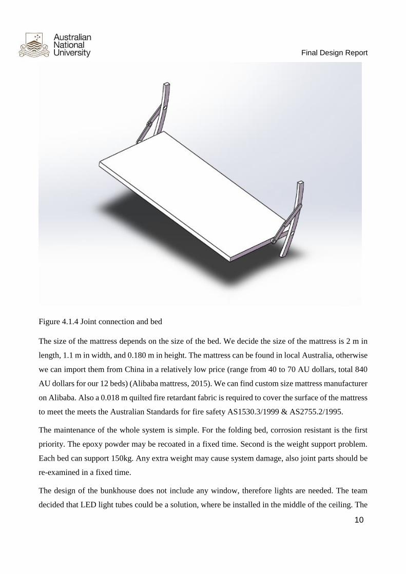
As for the connection joint between the wall and the bed, shown in Figure 4.1.3, stainless steel could
be the best choice due to the high stiffness and the relatively lower cost comparing with other
materials. Again we need to consider a person sleeping on the outer edge of the bed, it is very
important the system could balance the moment created by the person’s weight. The weight of the
stainless steel could be large enough to balance the system. The price of the connection joint is 15
AU dollars for each (need to be customized). Since we need two connection joints each bed, the total
price is 360 AU dollars.
Figure 4.1.3 Joint connection overview
Final Design Report
10
Figure 4.1.4 Joint connection and bed
The size of the mattress depends on the size of the bed. We decide the size of the mattress is 2 m in
length, 1.1 m in width, and 0.180 m in height. The mattress can be found in local Australia, otherwise
we can import them from China in a relatively low price (range from 40 to 70 AU dollars, total 840
AU dollars for our 12 beds) (Alibaba mattress, 2015). We can find custom size mattress manufacturer
on Alibaba. Also a 0.018 m quilted fire retardant fabric is required to cover the surface of the mattress
to meet the meets the Australian Standards for fire safety AS1530.3/1999 & AS2755.2/1995.
The maintenance of the whole system is simple. For the folding bed, corrosion resistant is the first
priority. The epoxy powder may be recoated in a fixed time. Second is the weight support problem.
Each bed can support 150kg. Any extra weight may cause system damage, also joint parts should be
re-examined in a fixed time.
The design of the bunkhouse does not include any window, therefore lights are needed. The team
decided that LED light tubes could be a solution, where be installed in the middle of the ceiling. The

Final Design Report
11
beam angle for a light tube is 120 degree. Considering the ceiling is around three metres and the total
length of the room is eight metres, it would be reasonable to install the light tube in the middle of the
room so that the light could cover the whole bunkhouse. The team considered that the light provided
by a single light tube, which is approximately 1900 lumens, may not be enough for the bunkhouse.
In this case two light tubes shall be installed in parallel in the middle of the ceiling. Meanwhile, the
light is adjustable since the light tube is designed to be able to turn on and off separately to adjust the
light intensity for different situations. The power consumption for a single LED light tube is
approximately 18W and the total power required for the light shall be around 40W.
The price of the light tubes is $14 in total (Alibaba light tube, 2015).
4.1.1 Storage Layer
As it was indicated in the requirements from the client, the bunkhouse should be able to convert to
storeroom when the rover is out in the field. The team decided to use the space under the floor be a
storage layer as.
Main challenge for this task is that the floor shall hold the weight of the rover, which is approximately
4000kg. There should install strong spandrel girder under the floor. However, adding a storage layer
would reduce the volume of spandrel girder and therefore reduce the weight-holding.
The team decided to use only the middle part of the space under floor as the storage space. The width
of the floor was approximately 3 m so the team decided that the 1.5 m range in the middle for storage
space could be reasonable, that is, no spandrel girder added underneath. The rest of the space would
be supported by the girder, and be used for holding the weight of the rover and people.

Final Design Report
12
Figure 4.1.5 Design of the storage space under the floor
Figure 4.1.5 shows the position of the storeroom. When the rover is in the garage, the wheels would
apply force to the ground. However, the force would be only applied on the two sides of the floor in
the garage. In this case the stress capacity of the floor in the middle could be lower than the sides. In
this way, the storage layer could be built under this area safely. As for the access to the storage layer,
several lids (floor panels) should be installed on the floor. The lids are in level with other parts of the
floor. The dimensions of the lid are 1 m long and 1.4 m wide and will cover two storage boxes so that
people can step on it (Shown in Figure 4.1.6 and 4.1.7). The lids have a relatively big surface to
reduce the pressure, and the weight is endured by multiple support points shown in Figure 4.1.7. The
volume for each individual box is around 0.5 m3, for a total volume of approximately 8m3.

Final Design Report
13
Figure 4.1.6 (left): Design of the storage area
Figure 4.1.7 (right): Blue area will be the supporting area that endure the weight of human.
Figure 4.1.8 Dimension of each individual store box in mm

Final Design Report
14
The design of the lids can provide access to the storage box for people. The AISI type 304 stainless
steel grid will be chosen as the main material for the lid due to its high ultimate tensile strength (515
MPa) and high yield strength (205 MPa). This stainless steel grid should be aligned closely in order
to provide a high durability when the rover is on it. When the research initially started, balsa wood
was considered to be the choice due to its low density and decent ultimate tensile strength. However,
after the ANSYS analysis, the result indicated that balsa wood cannot bear the force and pressure of
the rover. Therefore after comparison stainless steel is the best choice, approved by the ANSYS
analysis. The overview of the floor panels and lids is shown in the Figure below.
Figure 4.1.9 Metal grid flooring panels
The price of steel grid floor from Alibaba is $70 per metre. (Alibaba steel grid floor, 2015)
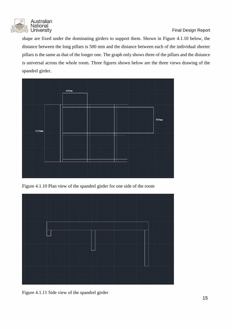
As for the material of spandrel girder that supports the stainless steel grid floor, pine wood is chosen
due to the lower density compared with metal, and high ultimate tensile strength (40 MPa) among the
wood. Specifically, pine wood pillars with a 90 mm× 45 mm cross section are used to support the
stainless steel floor as the dominating girders, and there are totally three rows of pillars in one side
underneath with a 500 mm distance between them. Shorter pine wood pillars with same cross section
Final Design Report
15
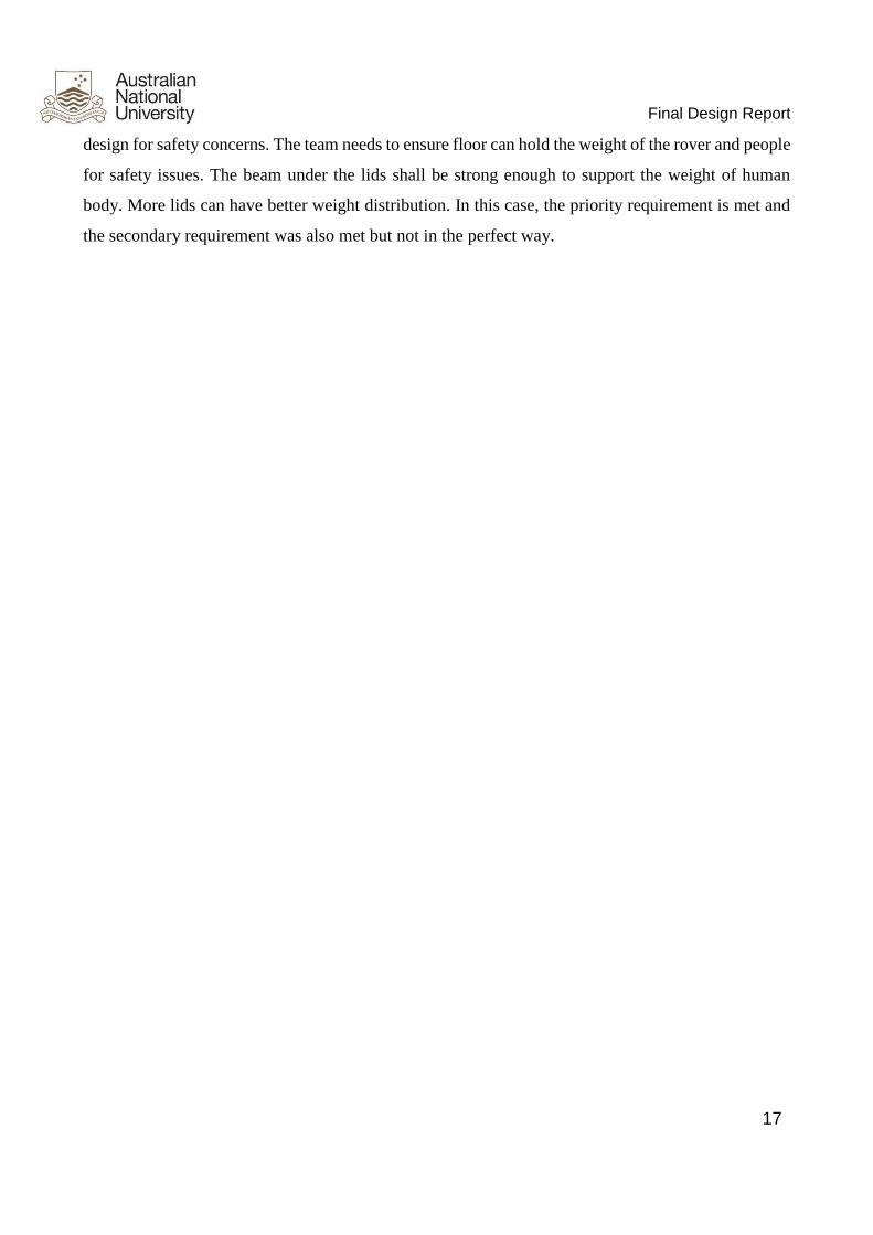
shape are fixed under the dominating girders to support them. Shown in Figure 4.1.10 below, the
distance between the long pillars is 500 mm and the distance between each of the individual shorter
pillars is the same as that of the longer one. The graph only shows three of the pillars and the distance
is universal across the whole room. Three figures shown below are the three views drawing of the
spandrel girder.
Figure 4.1.10 Plan view of the spandrel girder for one side of the room
Figure 4.1.11 Side view of the spandrel girder

Final Design Report
16
Figure 4.1.12 Front view of the spandrel girder
There were a few material choices available for the team when designing the spandrel girder, such as
structure steel and aluminium alloy. Considering the ability of load-bearing, structure steel could be
the best choice. However, the density of steel is much greater than the other two choices and if so the
total weight of the garage will be significantly large. Regarding to aluminium alloy, the density would
be an issue and the price could be another issue. The density of aluminium would be relatively lower
than that of steel. However, it is also considered to be too large for the garage. As for the price, the
price of aluminium beam is $25 per metre, which is much higher than that of pine wood. Pine wood
is strong enough to hold the weight and the price is relatively reasonable compared with the other two
choices. Moreover, the installation process could be less complicated if pine wood is chosen as the
material since there is no need for custom made components.
Therefore the team decides that structural treated pine wood would be reasonably applied for the
design due to the lighter density, enough beam stress and the relatively lower price. The floor will be
covered with metal grid to enhance the strength of the floor and also reduce the weight of the total
garage. The cross section of the structural treated pine is 0.09m * 0.045m, and we need 143m of them.
The price of pine is $5.15 per metre. The total price is $736.45 (Bunnings warehouse, 2015).
There are disadvantages for this design. One of them would be the limited storing space, since two
sides under the floor are filled with pine wood. The team have to make a trade-off between the storage
and the space for bearing weight. Secondly, this design contains too many lids. It may not very
convenient to take goods outside the storage layer. On the other hand, however, this is a reasonable
Final Design Report
17
design for safety concerns. The team needs to ensure floor can hold the weight of the rover and people
for safety issues. The beam under the lids shall be strong enough to support the weight of human
body. More lids can have better weight distribution. In this case, the priority requirement is met and
the secondary requirement was also met but not in the perfect way.

Final Design Report
18
4.1.3 Verification
The requirements of bunkhouse from client is shown below. Our design meet all requirements with
relatively low price. The total price of our bunkhouse design is $3892.45, which is accepted by our
client.
Table 4.1 Verification of bunkhouse and Storeroom
Verification
ID Reqd by Description
V1.0
R1.1
Inspect volume of garage by measuring length, width, height. The irregular edge
should be accurate. Use mathematical volume formula. Then sum several regular
part together to get entire volume. Compare with target value 62.58 m3
R1.2
Inspect the power consumption by measuring the voltage and current between
doorway access then using formula power=voltage × current to get power
consumption. Compare to target value 100W.
R1.3 Testing the load bearing by loading weight in garage. Put 0 kg to 8000 kg pressure
to test it whether it can support. Compare to the target value 8000kg.
R1.4 Test the force by applying load pressure on towing interface. Record the test value.
No target value match required.
V2.0
R2.1
Inspect volume of bunkhouse by measuring length, width and height. The irregular
edge should be accurate. Use mathematical volume formula. Then sum several
regular part together to get entire volume.
R2.2
Demonstrate living equipment by someone actually living in the bunkhouse, and
record the feedback. The simulator will operate the system in the same living
condition.
R2.3 Test the bed load bearing by applying load pressure on bed vary 500 N (50 kg) to
2000 N (200 kg). The maximum value should larger than target value 150 kg.
V3.0 R3.0
Inspect volume of storeroom by measuring length, width, height. The irregular edge
should be accurate. Use mathematical volume formula. Then sum several regular
part together to get entire volume. Compare with target value.

Final Design Report
19
4.2 HVAC
4.2.1 Heating & cooling (air conditioning)
According to the customer requirements for HVAC system listed in our previous part, the temperature
in MarsOz habitat in Arkaroola, South Australia should be kept between 20°C to 26°C. The average
environmental temperature and climate are recorded in appendix Figure 8.3. For the design
consideration, the highest temperature can reach 50°C. Therefore the garage design needs a proper
and effective heating & cooling system to control the temperature inside.
● Design choice - heating
For the heating system there are two methods: heater and air-conditioner.
(1) Heater
Most heaters are electric heaters, which transfer electrical energy to heat. On the one hand, the total
volume of the garage is around 62.6 m3 which is considerably large for relatively low efficiency of
the heater; on the other hand, the highest temperature in Arkaroola can reach more than 50°C, cooling
takes more important role compared with heating.
(2) Air-conditioner
The air-conditioner is mostly used for both heating and cooling. The major parts of an air conditioner
are: evaporator, condenser, expansion valve, and compressor. There are several advantages of AC:
1) Efficiency. The experiment shows the efficiency of AC is better than heater. Heater need more
time to response. Heaters need more time to warm up.
2) The safety factor of the air-conditioner is higher than heater since there is less risk of potential fire
issue.
3) The AC can both provide cooling and heating function. For the design efficiency and budget
consideration, AC is a better solution to control temperature in this design.
● Design choice - cooling
For the cooling system there are three potential methods: water-pipe, painting and air-conditioner.
(1)Water pipe
Water/coolant absorbs heat from garage to keep the temperature around 20-26°C. When water/coolant
reaches saturation, it will transfer to underground to wait until the temperature drop. The new
coolant/water will refill the pipe to keep temperature steady.
(2) Painting
Since most of heat comes from radiation of sun, painting gold or other material on the surface can

Final Design Report
20
reflect energy from the sun. This will keep garage at a comfortable temperature during the day.
Cooling function can also achieve by AC.
From the choice above, we can find that air-conditioner is a better method to control garage
temperature around 20°C to 26°C. Also the design needs some methods to improve performance like
painting. Painting will help to increase efficiency of AC, and it will keep whole garage as a
independent system. This will reduce the influence of radiation from the sun.
● Specification:
1. Insulating paints:
The list of price for painting is attached in appendix.
Due to empirical evidence, 1 litre of paint would cover about 8.6 m2. According to the graph in
appendix 8.5, the outer radius is 2.350 m, the length of garage is 8.2m. Therefore we can easily get
the outer surface area according to the formula of cylinder
𝑆 = 2𝜋𝑟ℎ + 2𝜋𝑟2 = 155.776 𝑚2
or equivalently, approximately 18.11 litres of painting. Considering the loss during painting or other
reasons, the total amount of paint should be 19 litres.
Reason:
A. From the reviews and comments of painting materials, Insulating Primer #14 performs well
in insulating radiation among the materials listed.
B. The price of Insulating Primer is $34.5 per gallon. The price is not as expensive as #18 Metal-
Prime.
From these two main factors, choosing Insulating Primer #14 as the material to paint. The total price
of 19 litres of painting is $172.50. The price of painting materials are listed in appendix.
4.2.2 Air conditioner
The air conditioner can operate for both cooling and heating purpose during day and night
respectively. The basic operation process is shown below (The air conditioning company, 2011).
Considering the comparatively small volume of the garage, the team decide to choose a normal air
conditioner instead of central air conditioner, which would be more expensive, hence there is no
necessity for the design. There are several choices of air conditioner from famous brands among
Australia.

Final Design Report
21
Figure 4.2.1 basic operation process of air conditioner
The most important issue needs to be concerned is the EER (energy efficiency ratio), which can be
found in the guide book for every air conditioner. In addition, air conditioner capacity (W) and power
output need also to be invested. According to the research, the comparison graph is shown below
(JoshKirschner, 2014.)
Figure 4.2.2 Room size and power required
Note: this diagram is used for cubic shaped room. However in this project, the volume of cylinder is
larger than square. Therefore the indicated power required would be smaller than practical value.
As for the radiation heat loss, it is prevented by painting method. This method will keep the habitat
as an independent system, that is, not absorbing heat from the sun, and loss heat from inside. The area
of the floor in garage is estimated to be 25 m2, so that the required power for garage, according to the

Final Design Report
22
figure above, is 3.5 kW both for heating and cooling.
.
Figure 4.2.3 Premium 3.5kW Reverse Cycle Split System: LG-P12AWN-14
Model number: LG-P12AWN-14
Price $1474
Cooling capacity 3.50kw
Heating capacity 4.00kw
Power input Cooling: 862W
Heating: 872W
Maximum Running Current Cooling: 5.6A, Heating: 7.1A
Air Flow Rate (Indoor, Max) 240 L/sec
Outdoor Noise (dB(A) ± 3) (Sound Pressure
Level¹) (H/M/L/S)
45 (Actual installed noise levels are varying,
which depends on the installed location)
Indoor Noise (dB(A) ± 3) (Sound Pressure
Level¹) (H/M/L/S)
39 / 33 / 23 / 19 (Actual installed noise levels
vary depending on the installed location)
Dimensions Indoor Product (W × H × D) 885 × 295 × 235
mm
Outdoor Product (W × H × D) 770 × 545 × 28
8mm
Weight (Indoor / Outdoor) 11 kg / 36 kg
Operation range: Cooling -10 ~ 48 degrees Heating -15 ~ 24
degrees
Table 4.2.1 AC technical specification
Final Design Report
23
Also the air conditioner system for garage is a split unit. Air conditioners are made up of two parts,
with one attached to the internal wall of the room, while the other installed on the outside to exhaust
heat out.
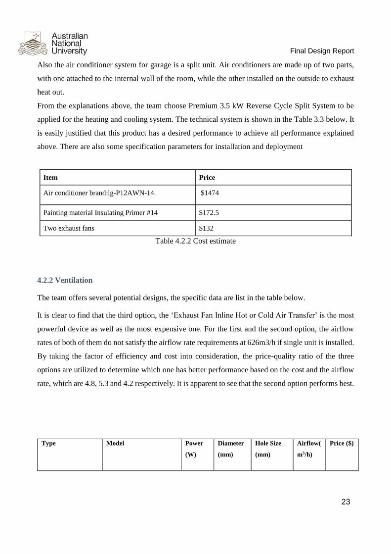
From the explanations above, the team choose Premium 3.5 kW Reverse Cycle Split System to be
applied for the heating and cooling system. The technical system is shown in the Table 3.3 below. It
is easily justified that this product has a desired performance to achieve all performance explained
above. There are also some specification parameters for installation and deployment
Item Price
Air conditioner brand:lg-P12AWN-14. $1474
Painting material Insulating Primer #14 $172.5
Two exhaust fans $132
Table 4.2.2 Cost estimate
4.2.2 Ventilation
The team offers several potential designs, the specific data are list in the table below.
It is clear to find that the third option, the ‘Exhaust Fan Inline Hot or Cold Air Transfer’ is the most
powerful device as well as the most expensive one. For the first and the second option, the airflow
rates of both of them do not satisfy the airflow rate requirements at 626m3/h if single unit is installed.
By taking the factor of efficiency and cost into consideration, the price-quality ratio of the three
options are utilized to determine which one has better performance based on the cost and the airflow
rate, which are 4.8, 5.3 and 4.2 respectively. It is apparent to see that the second option performs best.
Type Model Power
(W)
Diameter
(mm)
Hole Size
(mm)
Airflow(
m3/h)
Price ($)

Final Design Report
24
Vortice Vario
Exhaust Fan – Wall /
Window
38 230 262–267 480 100
Whisper Round
Exhaust Fan with
Draft Stop Brilliant
27 300 330 350 66
Exhaust Fan Inline
Hot or Cold Air
Transfer or
Extraction 20cm
Mixflow Ventair
130 200 230 700~820 195
Table 4.2.3 Choices of exhaust fan for ventilation
Final Design Report
25
Therefore, it is recommended to install two of the Whisper Round Exhaust Fan with Draft Stop
Brilliant so as to achieve the total airflow rate of 700 m3/h (beyond the desired airflow rate of 626m3/h)
and the total cost of the device is $132, which is greatly smaller than the third option for only single
unit, $195. The feature of the device is the lower noise (under 30dB while working).
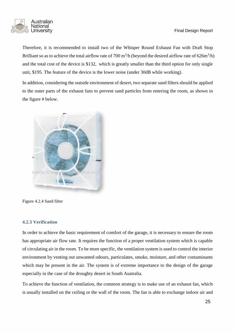
In addition, considering the outside environment of desert, two separate sand filters should be applied
to the outer parts of the exhaust fans to prevent sand particles from entering the room, as shown in
the figure # below.
Figure 4.2.4 Sand filter
4.2.3 Verification
In order to achieve the basic requirement of comfort of the garage, it is necessary to ensure the room
has appropriate air flow rate. It requires the function of a proper ventilation system which is capable
of circulating air in the room. To be more specific, the ventilation system is used to control the interior
environment by venting out unwanted odours, particulates, smoke, moisture, and other contaminants
which may be present in the air. The system is of extreme importance to the design of the garage
especially in the case of the droughty desert in South Australia.
To achieve the function of ventilation, the common strategy is to make use of an exhaust fan, which
is usually installed on the ceiling or the wall of the room. The fan is able to exchange indoor air and

Final Design Report
26
outdoor air. It is designed to eliminate indoor air pollution, and to regulate temperature and humidity.
Using an exhaust fan is a supplement to an air conditioning system. The next step should be choosing
a proper exhaust fan that satisfies the airflow requirement of the garage room. According to the
information provided by Engineering Toolbox, it is recommended to achieve a minimum of 10 air
changes per hour in the room combining the functions of garage, storage and bunkhouse, to remove
excess moisture. To work out the recommended capacity needed for the room, calculate the volume
of air in the room (length × width × height, all in metres) and multiply this by the number of air
changes to get the required air volume of the fan. (This will be adequate in most normal situations.)
Verification ID Reqd by Description
V4.1 R4.1 Test the temperature by measuring the temperature during the power
supply test which the air-conditioner will control the 138m3 space
temperature at about 26 degrees.
V4.2 R4.2 Analyse ventilation by simulating ventilation procedure. The simulation
graph about air flow show the orientation. There should be both flow in
and out air to achieve the ventilation goal.
Table 4.2.4 Verification of HVAC
The requirements of HVAC is providing a comfortable environment to the staff. Basically, there are
two main factors: temperature and airflow rate. As displayed in the table # above (from SDS), the
volume of the room is approximately 62.6 m3. Hence, the exhaust fan is recommended to achieve a
minimum airflow rate of 626 m3/h.
Initially, when considering the basic requirements of ventilation, three potential options of the exhaust
fan were provided which vary in their shape, mounted position, diameter, power, airflow rate and
price. The details of the three options are listed in table # below. All of them are available online
which could be delivered within Australia. As for air-conditioning, testing the temperature in a similar
volume room, to see the AC can achieve the temperature.
Note: because it is impossible to test in a real situation. Therefore, it can be estimated by comparing
to a similar size room. Placing a thermometer in a similar size room to test whether it can reach the
goal.
The functionality of the ventilation system is tested by using an air flow metre to see whether the inside
environment meets the target value, 626 m3/hr after using the two proposed exhaust fans.

Final Design Report
27
4.3 Door Access
Figure 4.3.0 Main garage door (CAD drawing)
4.3.1 Operation and dimension description
● Main garage door
Figure 4.3.1 Main garage door

Final Design Report
28
To ensure the rover to enter the garage easily, the size of the main door should be large enough. Given
the size of the rover is approximately 6 m in length, 3 m high and 2.2 m wide, the design dimension
of main garage door is approximately 3.21 m in high and 2.78 m wide (Figure 4.3.1). The main garage
door also performs as a part of the Figure 8.5 from the past design.
However, since the client requests the climb slopes of the rover to be around 20 degree, and 3.21 m
height of the main garage door provides approximately 30 degrees ramp. In order to achieve 20
degrees’ ramp, the group presents another pair of extendable ramps with 1.7m in length. Thus, the
total length of the ramp is main garage door’s height plus length of the extendable ramp, which is
approximately 4.91 m, and this provides a ramp angle around 20 degrees (As shown in Figure 4.3.2
below). When the main garage door and ramp fully open, consider safety issue, the group designs a
safety lock on human access door to ensure it close tightly when rover driving on the ramp.
Figure 4.3.2 Main door fully open
The ramps are installed outside the door and using axle to make it able to unfold. When the door is
closed, the ramps will naturally hang on the door due to the gravity, and a lock on them to make the
ramps stay cling to the main garage door. The opening mechanism of the main garage door is
presented by a cable and a motor. The motor provides power enable the cable to lay down and lift up
the door, and the door opens outward. There are two electric capstan have power approximately 1kw
for each. (As shown in Figure 4.3.3 below). When the main garage door closed, and the people

Final Design Report
29
requires go out the garage, there is a separate 1.8m length single lift ladder prepared in the storage
room for people to climb up and down.
Figure 4.3.3 Main door close
Both the inner side of the door, which is the surface of the ramp will be made rough or added some
grooving to increase friction. (As shown in Figure 4.3.4)
Figure 4.3.4 Ramp
● Human access door
Moreover, the design also include a human access door in main garage door, it develops on client’s
original drawing. The human access door provides access to habitats and other visitors when there is
no require to open the main garage door, and the human access door can save heat and air of the
garage. It opens toward outside, and the top and bottom of the human access door has semicircle

Final Design Report
30
shape, and there is a rectangle between two semicircles. The radius of both semicircle is 0.43m, and
rectangle in the middle has 0.79 in wide and 0.85 length. Thus, the total height of the human access
is approximately is 1.64m (As shown in Figure 4.3.1). The human access door is consistency with
other human access door of the habitat. The group design a handle outside the human access door,
which the people and hold on it when they climb up and down by the 1.8m single lift ladder.
● Air tightness
Furthermore, the client requests air tightness for both main garage door and human access door. Based
on budget and practicability, the group presents the synthetic rubber seals that contains several types
of synthetic materials and also to achieve it, the length for the synthetic rubber seals is approximately
13.46m.
4.3.2 Features of our design
The overall structure of our design is simple, and easy to operate. Since each section is independently,
the maintenances are easier and would not interrupt with other components or systems; and the main
garage door functions as a part of the ramp, it is more cost-effective. Moreover, the existence of
human access door provides another does not require to open the main garage door frequently if it is
not necessary, it extended main garage door’s life time directly, and also save air and heat inside the
garage. Based on the simulated results, our 2410 kg aluminium alloy door will be able to support
4000 kg rover. And the grooving surface increases frictions and level of safety, and also avoids
slippery occurs.
The synthetic rubber seals are widely used for sealing in the market, relatively low cost and has the
desired characteristics as design requests such as, high/low temperature resistance, excellent aging
resistance and air tightness. Moreover, it also has ozone and oil resistance.
The synthetic rubber seals are widely used for sealing in the market, relatively low cost and has the
desired characteristics as design requests such as, high/low temperature resistance, excellent aging
resistance and air tightness. Moreover, it also has ozone and oil resistance.

Final Design Report
31
4.3.3 Materials and models
After simulated several materials by the ANSYS, the group decides the material of the cable is
stainless steel, 6061 aluminium alloy for the main garage door, and the weight of main garage door
is approximately 2410 kg.
6061 aluminium alloy (As shown in Figure 4.3.5 below) will be chosen as the main material of the
door and the ramp. This aluminium alloy has 45,000 psi ultimate tensile strength and the yield strength
of it is 40,000 psi. These two main properties ensure that it has a large strength and easy machinability.
Since the dimension of the door for the garage is 3.1m × 2.7m, this aluminium alloy can ensure its
safety when the rover is on the door. ANSYS are used to verify the safety issue of the aluminium
alloy door. From the module created in ANSYS and the analysis, it illustrates that the door undergoes
a low equivalent stress and there is no fracture in each part when using the 6061 aluminium alloy.
Ramp are also analyzed through ANSYS to ensure the safety and strength of it when rover is on it.
Moreover, the density of the 6061 aluminium alloy is 2.7g/cm3, which is much lower than steel.
Although steel could be used on the garage door and ramp, its high density will lead to overweight to
the door, which does not match the customer requirements. Balsa wood is first considered to be the
choice of the door. However, after the analysis in ANSYS, it is found that the door can’t force the
rover when using the balsa wood since its low ultimate tensile strength (13.8 MPa). Hence, the best
choice of the door and the ramp for this garage is 6061 aluminium alloy.
Figure 4.3.5 6061 Aluminium Alloy

Final Design Report
32
The group has chosen PowerTools K5000-P (As shown in Figure 4.3.6 below) model of electric
capstan in our system, and we require two of it. The maximum required pulling forces to lift up/down
the main garage door and ramp is 8500 N. This type of electric capstan has 22680 N load capacity,
which will provide sufficient forces to achieve operating mechanism of the door. Its dimension is
41.5 × 34.5 × 28.5 cm, which is small enough for the group to put it on the roof.
Figure 4.3.6 PowerTools K5000-P electric capstan
The 7x19 Stainless cable with diameter 5 mm (As shown in Figure 4.3.7) will use in the system to
assist the door opening process. This type of stainless cable suitable for running rigging, control
cables, cranes and winches, and it is widely used in the industry. As demonstrated before, the required
pulling forces are 8500 N, and the 7x19 stainless cable’s breaking strain is 1276 kg (12760 N), which
will satisfied our requirements.
Figure 4.3.7: 7x19 Stainless cable with diameter 5mm
For air tightness, the group chooses TH-QC301 synthetic rubber sealing strips (As shown in Figure
4.3.8 below). This synthetic rubber sealing strips can operate in wide temperature range -30 ~ 120°C,
Final Design Report
33
its dimension is 0.45 × 0.22 × 0.15mm. It contains different types of rubber to achieve our
requirements. The NBR provides an excellent oil resistance; EPDM has excellent resistance to
weather and ozone, good resistance to heat, low temperature and chemical; NR has high elasticity
with good chemical strength; CR is generally good resistance to ozone, aging and chemical as well;
and Silicone provides stably in high and low temperature.
Figure 4.3.8: YH-QC301 Synthetic rubber sealing strips
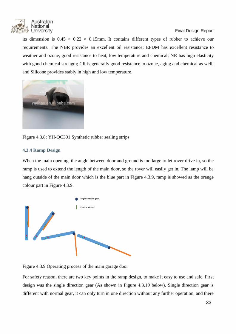
4.3.4 Ramp Design
When the main opening, the angle between door and ground is too large to let rover drive in, so the
ramp is used to extend the length of the main door, so the rover will easily get in. The lamp will be
hang outside of the main door which is the blue part in Figure 4.3.9, ramp is showed as the orange
colour part in Figure 4.3.9.
Figure 4.3.9 Operating process of the main garage door
For safety reason, there are two key points in the ramp design, to make it easy to use and safe. First
design was the single direction gear (As shown in Figure 4.3.10 below). Single direction gear is
different with normal gear, it can only turn in one direction without any further operation, and there

Final Design Report
34
are few blockers inside the gear, to block it turning to another direction. The material to make the
gear will be steel, because it is cheap and strong to support the force. For strong single direction gear,
it is able to support 1000 kg, our lamp made by aluminium alloy, it is not heavy for the gear to support.
And also we will also design a switch for the single direction gear, which can control it to turn in
another direction. For example, it only turn in clockwise, after press the switch, the blocker inside the
gear will shrink, so the gear will be able to turn in anti-clockwise.
Figure 4.3.10 Single direction gear
The second design is the electromagnet, which act as the magnet with power support. It will be located
at the end of the ramp, to make sure the ramp is bonded with the main door. So the ramp will not
drops down in case any accident happens. The electromagnet need to support by 24 V power supply,
we plan to have two magnets at the end of the ramp, each of its can support 100 kg weight, so with
these will make sure the ramp will boned with the main door.
Figure 4.3.11 Electromagnet

Final Design Report
35
According to Figure 4.3.9 above, at the beginning ramp is hang out side of the main door, with the
main door opens, the ramp will still be bonded with the door, when the main door opens more than
45 degrees, the operator may press the magnet switch, so the ramp will open automatically under the
effect of weight, because of the single direction gear, the ramp will open in one direction slowly, it
won’t shake or turn to another direction, that will make sure it will be safe to operate it. With the main
door opening, the ramp will fully extend until it become one unit.
When the door closing, the ramp won’t turn back, because the single direction gear, so the operator
may press the button of the gear, in that case, the ramp may turn back in short time period, the operator
will control the gear to make sure the ramp close slowly, and finally the magnet will seal the ramp
again to finish the whole process.
Price
Components Prices ($)
DC motor 860
Stainless steel cable (7x19, most flexible wire,
widely used for running rigging, control cables,
cranes and winches) total length: 15m
diameter: 5mm
75
Main garage door 5,000 - 5,500
Synthetic rubber 270
Single direction gear 160
Table 4.3.1 Total price of the door design
From the table above, the total costs for the design is between $6,365 - 6,865. The price for main
garage door and synthetic rubber is based on Chinese market price.

Final Design Report
36
4.3.5 Interact with other systems
The overall design of the main garage door system is independent from other subsystems. However,
there is a motor in the design which requires electricity from the front section of the cargo.
4.3.6 Future Consideration
After communicated with the client during the preliminary design review presentation (PDR), the
client concerned the weight of the main garage door is too heavy. In order to reduce the weight of the
door, the group design to only make the door solid for the wheel trail section, and the rest part is
hollow with cellular structure supported. Thus, a force body diagram is applied to calculate the
feasibility of this design.
Figure 4.3.12 The Force Body Diagram (FBD) for the rover
As shown in Figure 4.3.12 above, the equilibrium equations can be calculated:
𝑚𝑔𝑠𝑖𝑛20° = 𝜇𝑁
𝑚𝑔𝑐𝑜𝑠20° = 𝑁
Since the FBD is on one side of the rover wheel, the weight mg should be one fourth for the whole
rover which equals to 1000kg × 9.8N/kg = 9800N. Therefore, the normal force should be 9800 N ×
cos20° = 9209 N. According to P = FS, F equals to the normal force 9209 N and the area between the
wheel and ground is measured to be 0.03 m2 for each wheels. Hence, the pressure equals to 307 kPa.

Final Design Report
37
This figure is far less than the ultimate tensile strength and therefore using 6061 aluminium alloy is
quite safe for the whole garage.
Based on the calculation, the design is feasible, nevertheless, the structure is too complicated to test
by ANSYS. Therefore, the group is lacking the test results.
4.3.7 Verification
The requirements of doorway access from client is shown below. The designed dimension of the is
3.21×2.78m, the height is longer than the target value and the width is narrower than the target value
(V1.2 in Table 4.3.2 below). The purpose of design is to reduce the surface area of the main garage
door in order to lower the weight, and with designed dimension, the rover still can be able get access.
The dimension of the human access door is 1.64×0.85m, its dimension is consistent with other human
access doors on the habitat (V1.2 in Table 4.3.2 below). According to the Force Body Diagram (FBD)
analysis above, it is feasible in theory. (V1.3 in Table 4.3.2 below). The budget of doorway access is
accepted by the client.
Verification
ID Reqd by Description
V1.2 R1.2 Inspect length of doorway access by measuring the length. Compare
to the target value 3.181×3.181 m.
Inspect the power consumption by measuring the voltage and current
between doorways. Compare to target value 100 W.
Inspect the length of door for man pass by measuring the length and
height. Compare to the target value 2×1.5 m.
V1.3 R1.3 Testing the load bearing by loading weight in garage. Place 8000 kg
load as a stress test. Compare to the target value 8000 kg.
V10.0 R10.0 Analyse the budget of system by carrying out costing analysis on
subsystems and components. Costs include labour loss and material.
Compare to the budget.
Table 4.3.2 Verification of the doorway access design

Final Design Report
38
4.4 Docking Module
4.4.1 Main Compartment
The main compartment of the adapter module is the body that connects the Habitat and Garage
modules. It houses all the components within adapter module and is the main body through which
people and goods are moved between the Garage and Habitat modules. The dimensions of the main
structure have been constrained by the client.
4.4.1.1 Design Description
The docking module is a simple aluminium structure. There is an aluminium floor plate that is
supported by beams positioned under the plate as well as four legs welded to the support beams. There
are beams bolted to the floor that extend to the roof of the docking module. A weatherproof tarpaulin
canopy is used as a roof and wall material where possible. The structure is stored in the garage and
can be assembled on site. The structure is assembled using M10 hex bolts. The length of the system,
between garage and habitat module, is 2.8 m. The diagram below shows a CAD model of the docking
module excluding the tarpaulin canopy and wheel attachment.
Figure 4.4.1 CAD model of docking module frame and floor
The major components of the docking module are the floor plate, support beams and legs, side beams,
face plates and the canopy. These components and their analysis are discussed in detail in the
subsequent sub-sections.

Final Design Report
39
Adapter Module Specifications Summary
Weight: 119 kg
Load Capacity: 200 kg
Securing Mechanism: M10 × 100 Structural Grade 8.8 Zinc Plated Hex Bolt Fastener Assembly
Number of legs: 4
Factor of Safety (Weight): 6
Mobility System: Integrated Wheel and Pad Castor
Number of wheels: 4
Size: 2.8m× 1.8m× 2.0m (Main Compartment)
Roof: 240GSM Tarpaulin

Final Design Report
40
4.4.1.2 Cost Summary
The table below details the approximate component costs of the main compartment.
Name Description Unit Cost ($AUD) Quantity Total Cost ($AUD)
Fastening Assemblies Total cost of all fastening assemblies used N/A N/A 124.72
Aluminium Floor Plate 2800x1800x5mm Aluminium Treadplate ~690.50 1 ~690.50
Support Beam 850x100x100x6 Aluminium 6061 Rectangular Tube ~100.58 2 ~201.16
Support Beam 1830x100x100x6 Aluminium 6061 Rectangular Tube ~216.55 2 ~433.10
Support Beam 900x100x100x6 Aluminium 6061 Rectangular Tube ~106.50 1 ~106.50
Leg Beam 1048x60x5 6060-T5 Aluminium Hollow Tube ~95 4 ~380
Castor Wheel Adjustable levelling castor with wheel and pad $71.50 6 ~429
Side beam Standard (ROM) 1830x100x5 Side Beam Aluminium 6060-T5 ~96.60 4 ~386.40
Side beam Extended (ROM) 1830+x100x5 Side Beam Aluminium 6060-T5 ~96.60 8 ~772.80
Face End Plate 2000x1800x2 Aluminium 6061 Plate ~220 2 ~440
Face Side Plate 1800x1800x2 Aluminium 6061 Plate ~220 4 ~880
Total: ~$4844.22
Table 4.4.1 Docking module main compartment approximate component cost
Final Design Report
41
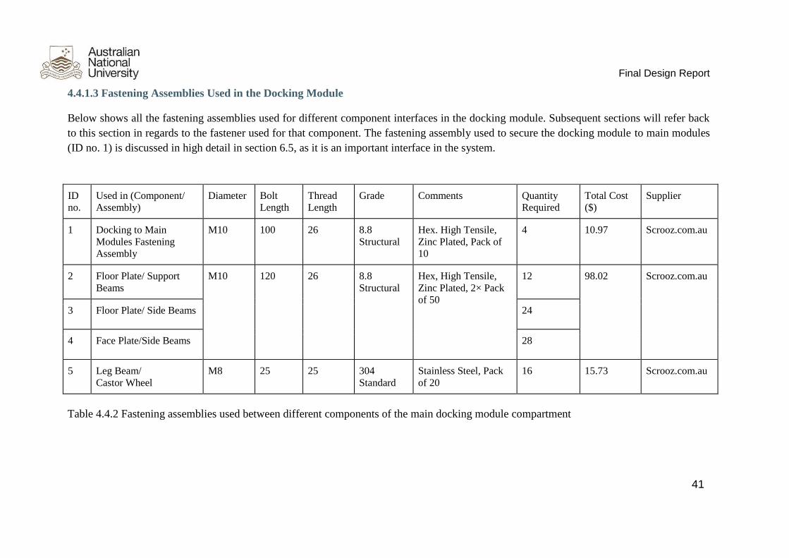
4.4.1.3 Fastening Assemblies Used in the Docking Module
Below shows all the fastening assemblies used for different component interfaces in the docking module. Subsequent sections will refer back
to this section in regards to the fastener used for that component. The fastening assembly used to secure the docking module to main modules
(ID no. 1) is discussed in high detail in section 6.5, as it is an important interface in the system.
ID
no.
Used in (Component/
Assembly)
Diameter Bolt
Length
Thread
Length
Grade Comments Quantity
Required
Total Cost
($)
Supplier
1 Docking to Main
Modules Fastening
Assembly
M10 100 26 8.8
Structural
Hex. High Tensile,
Zinc Plated, Pack of
10
4 10.97 Scrooz.com.au
2 Floor Plate/ Support
Beams
M10 120 26 8.8
Structural
Hex, High Tensile,
Zinc Plated, 2× Pack
of 50
12 98.02 Scrooz.com.au
3 Floor Plate/ Side Beams 24
4 Face Plate/Side Beams 28
5 Leg Beam/
Castor Wheel
M8 25 25 304
Standard
Stainless Steel, Pack
of 20
16 15.73 Scrooz.com.au
Table 4.4.2 Fastening assemblies used between different components of the main docking module compartment

Final Design Report
42
4.4.1.4 Docking to Main Modules Interface
The adapter module needs to be securely attached between the Garage and Habitat sections. A secure
connective interface at each end of the adapter module is required to achieve this. This is done using
fastening assemblies (bolt, nut & washer). Fastener assemblies are widely used in construction for
their relative low price and lifespan for the structural strength they provide.
A suitable fastener assembly is supplied by “scrooz.com.au”. It has a diameter of 10 mm, a length of
100mm for a length of engagement of 77 mm. The length of the thread is 26 mm. Out of the total
length of engagement (77 mm), 3mm will be threaded and the remaining is smooth. The diameter of
the hole is 12mm, considered a loose fit, for easier fitting.
Figure 4.4.2 fastening assembly diagram
Fastener Bolt Benchmarking Process

Final Design Report
43
The fastening assemblies are not exclusively responsible of supporting the gross weight of the
docking module; as it has legs designed to support the weight. The bolt must be able to withstand
3924 N of shearing force. The stress on the fastener bolt will be primarily due to shearing forces. It
is assumed that shear forces to the bolt are attributed solely to the weight of the docking module and
its carrying contents. The weight of the docking module is a maximum of 200 kg; which can internally
support a payload of 200 kg; for a total of 400 kg (3924 N). (Sidenote: Originally, the docking module
was 200kg, however in the new design, the docking module is 100kg;this section assumes a 200kg
docking module).
The fastener bolt must have a minimum shear strength of 3924 N. Shear strength is approximately
0.60 of ultimate tensile strength in a bolt. The ultimate tensile strength of a specific grade and diameter
of a bolt is given by (Portland Bolt, 2015):
𝑠𝑡𝑒𝑛𝑠𝑖𝑙𝑒 = 𝑡𝑚𝑖𝑛 × 𝑎
𝑠𝑠ℎ𝑒𝑎𝑟 ≈ 𝑠𝑡𝑒𝑛𝑠𝑖𝑙𝑒
𝑊ℎ𝑒𝑟𝑒:
𝑠𝑡𝑒𝑛𝑠𝑖𝑙𝑒 = 𝑈𝑙𝑡𝑖𝑚𝑎𝑡𝑒 𝑡𝑒𝑛𝑠𝑖𝑙𝑒 𝑠𝑡𝑟𝑒𝑛𝑔𝑡ℎ
𝑠𝑡𝑠ℎ𝑒𝑎𝑟 = 𝑆ℎ𝑒𝑎𝑟 𝑠𝑡𝑟𝑒𝑛𝑔𝑡ℎ
𝑡𝑚𝑖𝑛 = 𝑀𝑖𝑛𝑖𝑚𝑢𝑚 𝑡𝑒𝑛𝑠𝑖𝑙𝑒 𝑠𝑡𝑟𝑒𝑛𝑔𝑡ℎ 𝑜𝑓 𝑏𝑜𝑙𝑡 𝑔𝑟𝑎𝑑𝑒
𝑎 = 𝑆𝑡𝑟𝑒𝑠𝑠 𝑎𝑟𝑒𝑎 𝑜𝑓 𝑑𝑖𝑎𝑚𝑒𝑡𝑒𝑟
Fastener Bolt Benchmarking
The ultimate tensile strength of bolt grades 4.6 and 8.8 are shown below. The tensile stress area of
various diameter bolts are also shown below. These are used in benchmarking.
Bolt grades and Ultimate Tensile Strength
Grade MPa (N/mm2)
4.6 400
8.8 830
Area under tensile stress
Diameter (mm) Area (mm)
M6 20.1
M8 36.6
M10 58
M12 84.3
M16 157
Table 4.4.3 fastener information used for benchmarking

Final Design Report
44
Different types of bolts from various suppliers are benchmarked against their cost and shear strength. A minimum factor of safety of six is
required
Name Diameter Gra
de Min Tensile
Strength Stress
Area Ultimate Tensile
Strength (N) Maximum Shear
Force (N) Factor of
Safety Total
Cost M16x130 HDG 8.8 Struct 16 8.8 830 157 130310 78186 19.9 28.53
M12x140 HDG 8.8 Struct 12 8.8 830 84.3 69969 41981.4 10.7 23.00
M8x130 BLK 8.8 HT BN 8 8.8 830 36.6 30378 18226.8 4.6 22.22
M6x130 HDG 4.6 HEX BN 6 4.6 400 20.1 8040 4824 1.2 7.17
M8x130 ZP 4.6 HEX BN 8 4.6 400 36.6 14640 8784 2.2 8.44
M8x130 HDG 4.6 HEX BN 8 4.6 400 36.6 14640 8784 2.2 12.80
M10x130 BLK 4.6 HEX BN 10 4.6 400 58 23200 13920 3.5 11.50
M10x130 HDG 4.6 HEX BN 10 4.6 400 58 23200 13920 3.5 12.94
M10x130 ZP 4.6 HEX BN 10 4.6 400 58 23200 13920 3.5 11.50
M12x130 High Tensile Grade 8.8 ZP
Box of 50 12 8.8 830 84.3 69969 41981.4 10.7 65.53
M10x130 High Tensile Grade 8.8 ZP
pack of 50 10 8.8 830 58 48140 28884 7.4 53.46
M10x130 Grade 4.6 Galvanised Box
of 50 10 4.6 400 58 23200 13920 3.5 42.17
Table 4.4.4 benchmarking of different types of fasteners

Final Design Report
45
4.4.1.5 Main Compartment Floor
An aluminium tread plate spans the length of the docking module. It is 2.8m long and 1.8m wide,
with an area of 5.04 square metres. The floorplate has a thickness of 5mm. The cost of the plate alone
is $ 690.50
Floor Material and Thickness Selection Process
The main compartment of the adapter module must be able to hold 200kg.The adapter module has
support beams under it. However, there will be areas of the floor that is unsupported by the legs. The
unsupported areas of the compartment floor must be able to support a 200kg load.
Consistent with other components and subsystems, the floor’s most prioritised qualitative attributes
are: 1. as cheap as possible; and 2. as light as possible. The best floor according to these attributes
must be chosen. The independent variables that affect these attributes are shown below. These
variables affect the plate thickness.
● Material (Steel vs. Aluminium): Different materials have different Young’s modulus and
Poisson’s ratio.
● Unsupported Area: The unsupported area affects how thick the material needs to be to support
the required load. The number of supports will determine the unsupported floor area.
Two possible configurations for floor support beams are shown below. For the first configuration, the
maximum unsupported floor area is 900 × 1000 mm; for the second, the maximum unsupported area
is 900 × 700 mm.
The stress for varying materials and unsupported areas are calculated; the minimum thickness is
determined such that the stress is below the material's yield stress. The cost and weight are then
derived from material and thickness. Naturally, more support for the floor plate results in a thinner
plate; however it is a trade-off with the cost of the support beams. Assumptions and points regarding
the benchmarking process:
● The floor plate loading will have a factor of safety of six, standard in structural design in
buildings (Engineering Toolbox FOS, 2015). Therefore, a 1200kg (11772N) load will be used
in calculations.
● The floor is simply supported under a uniformly distributed load of 1200kg (11772N).
● The minimum thickness will be to a whole mm value.

Final Design Report
46
Figure 4.4.3 possible configurations for floor support beams

Final Design Report
47
Floor Benchmarking
An online tool by ‘efunda’ to calculate stress and displacement in simply-supported rectangular plate
under a uniformly distributed load is used for the benchmarking (efunda, 2015).
The two materials considered are aluminium and steel. Table 4.4.5 below outlines their relevant
physical strength properties. Material thickness is determined such that the stress on the plate is less
than the yield strength.
Material Properties Material Young's Modulus (GPa) Poisson's Ratio Yield Strength (MPa)
Aluminium 6061 Alloy 70 0.33 27
Stainless Steel 210 0.3 81
Table 4.4.5 material properties (Alumatter, 2010)
Maximum Unsupported Area Configurations 1 and 2
Leg
Configuration Unsupported
Length (mm) Unsupported Width
(mm) Area (m^2)
Config. 1 900 1000
Config. 2 900 700
Table 4.4.6 maximum unsupported area for each floor support configuration
Support
Configuration Young's
Modulus Poisson's
Ratio Area Distributed Loading
(MPa) Required Thickness
(mm) Aluminium 2-Pair
Support 70 0.33 0.9 13080.0 5
Aluminium 3-Pair
Support 70 0.33 0.63 18685.7 5
Steel 2-Pair Support 210 0.3 0.9 13080.0 3
Steel 3-Pair Support 210 0.3 0.63 18685.7 3
Table 4.4.7 required thickness calculation for different materials in different configurations
Material Density (kg/m^3) Thickness (mm) Volume
(m3) Weight
(kg) Cost (ROM)
Aluminium
6061 2720 5 0.0252 69 $690.48
Steel 7850 3 0.01512 119 $650
Table 4.4.8 Quantity and cost for each material. (Engineering Toolbox MAD, 2015)

Final Design Report
48
The configuration of supports do not affect the minimum thickness of the plate. The material is the
sole variable responsible for thickness. The company, “Specialist Metal Fabricators”, supply 5mm
aluminium tread plate for $137/m2 (Rapid Fab, 2015); a total cost of $690.48 for the floor. “Scott
Metal’s” fabricates 3 mm steel tread plates for $130/m2 (Scott Metals, 2015); for a total cost of $650.
The Aluminium tread-plate is the most suitable choice, costing $40.48 more in exchange for a 50 kg
weight saving.
4.4.1.6 Support Beams and Legs
The main compartment is propped up with support legs and cross beams. Two support beams, each
having two having support legs, span the width of the adapter module. One support beam spans the
length of the module. Aluminium alloy round hollow tubes is used as opposed to steel to reduce
weight of the system.
Support Beams
Five aluminium horizontal beams support the adapter module floor plate to reduce its thickness. The
floor plate is bolted down against the beams using fastener assembly 2 from section 4.4.1.3. The
configuration is shown below in figure 4.4.4. They are 100×100 mm aluminium rectangular hollow
tubes with 6mm thickness. The total length of the beams are 6.26m for an approximate cost of $740.77
($118.33/m). This value is extrapolated from the supplier “Williamstown Metal Merchants Pty. Ltd.”
that supplies 300 mm lengths for $25.50.

Final Design Report
49
Figure 4.4.4 floor support diagram
Stress in Support Beams For analysis, we deduce the beam types are:
● Beam 1: Cantilever beam under concentrated point load at free end
● Beam 2: Fixed beam under concentrated point load at centre
● Beam 3: Fixed beam under concentrated point load at centre
A tool to design beam members under compression and column buckling by ‘Advanced Mechanical
Engineering Solutions’ aids in calculating resulting stress (Advanced Mechanical Engineering
Solutions SBD, 2015). We require the maximum bending stress to be less than 27MPa (Yield strength
of aluminium).
Beam Specifications Metric Unit Value Width mm 100 Height mm 100 Thickness mm 6 Modulus of Elasticity GPa 70 Second Moment of Area cm4 492 Cost $/m 118.33
Table 4.4.9 floor support beam specifications
Analysis Length Weight Load Target Maximum Bending Stress
Beam Type 1 895 8.764 1962N < 27MPa 17.6
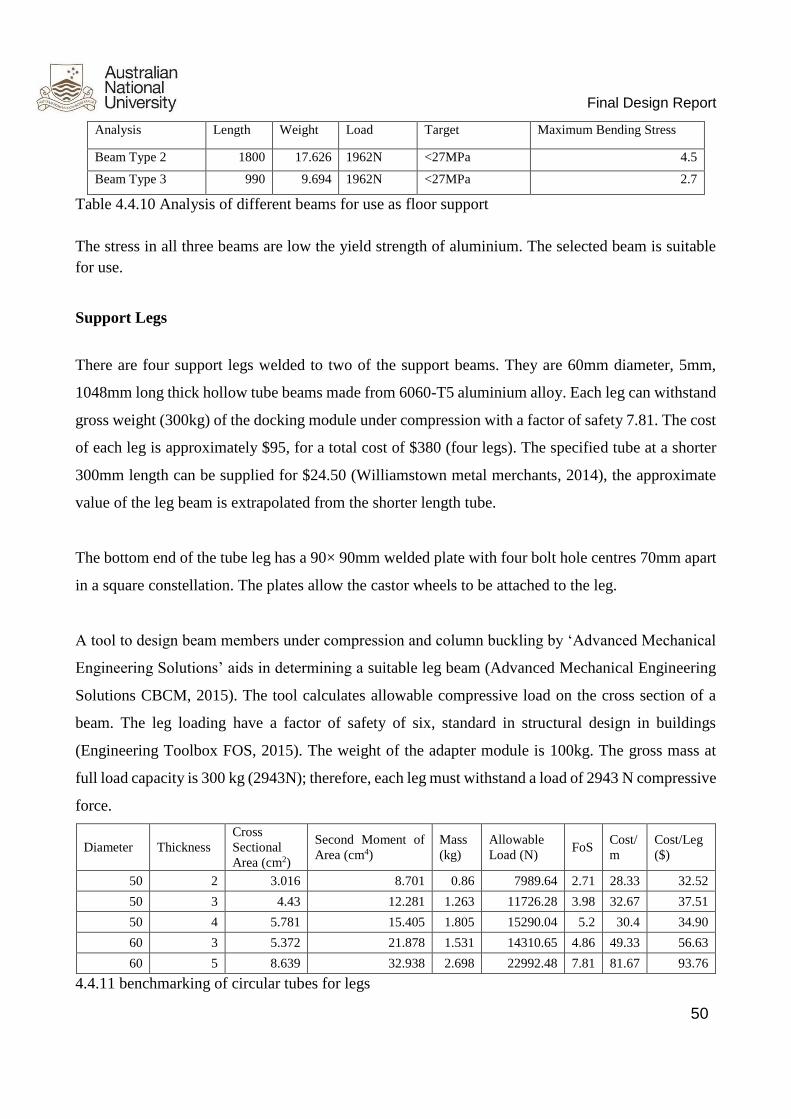
Final Design Report
50
Analysis Length Weight Load Target Maximum Bending Stress
Beam Type 2 1800 17.626 1962N <27MPa 4.5
Beam Type 3 990 9.694 1962N <27MPa 2.7
Table 4.4.10 Analysis of different beams for use as floor support
The stress in all three beams are low the yield strength of aluminium. The selected beam is suitable
for use.
Support Legs
There are four support legs welded to two of the support beams. They are 60mm diameter, 5mm,
1048mm long thick hollow tube beams made from 6060-T5 aluminium alloy. Each leg can withstand
gross weight (300kg) of the docking module under compression with a factor of safety 7.81. The cost
of each leg is approximately $95, for a total cost of $380 (four legs). The specified tube at a shorter
300mm length can be supplied for $24.50 (Williamstown metal merchants, 2014), the approximate
value of the leg beam is extrapolated from the shorter length tube.
The bottom end of the tube leg has a 90× 90mm welded plate with four bolt hole centres 70mm apart
in a square constellation. The plates allow the castor wheels to be attached to the leg.
A tool to design beam members under compression and column buckling by ‘Advanced Mechanical
Engineering Solutions’ aids in determining a suitable leg beam (Advanced Mechanical Engineering
Solutions CBCM, 2015). The tool calculates allowable compressive load on the cross section of a
beam. The leg loading have a factor of safety of six, standard in structural design in buildings
(Engineering Toolbox FOS, 2015). The weight of the adapter module is 100kg. The gross mass at
full load capacity is 300 kg (2943N); therefore, each leg must withstand a load of 2943 N compressive
force.
Diameter Thickness Cross
Sectional
Area (cm2)
Second Moment of
Area (cm4) Mass
(kg) Allowable
Load (N) FoS
Cost/
m Cost/Leg
($)
50 2 3.016 8.701 0.86 7989.64 2.71 28.33 32.52
50 3 4.43 12.281 1.263 11726.28 3.98 32.67 37.51
50 4 5.781 15.405 1.805 15290.04 5.2 30.4 34.90
60 3 5.372 21.878 1.531 14310.65 4.86 49.33 56.63
60 5 8.639 32.938 2.698 22992.48 7.81 81.67 93.76
4.4.11 benchmarking of circular tubes for legs
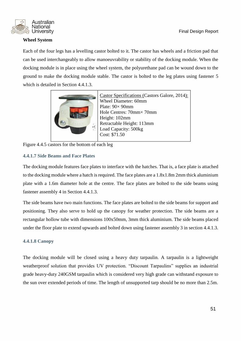
Final Design Report
51
Wheel System Each of the four legs has a levelling castor bolted to it. The castor has wheels and a friction pad that
can be used interchangeably to allow manoeuvrability or stability of the docking module. When the
docking module is in place using the wheel system, the polyurethane pad can be wound down to the
ground to make the docking module stable. The castor is bolted to the leg plates using fastener 5
which is detailed in Section 4.4.1.3.
Castor Specifications (Castors Galore, 2014): Wheel Diameter: 60mm Plate: 90× 90mm Hole Centres: 70mm× 70mm Height: 102mm Retractable Height: 113mm Load Capacity: 500kg Cost: $71.50
Figure 4.4.5 castors for the bottom of each leg
4.4.1.7 Side Beams and Face Plates
The docking module features face plates to interface with the hatches. That is, a face plate is attached
to the docking module where a hatch is required. The face plates are a 1.8x1.8m 2mm thick aluminium
plate with a 1.6m diameter hole at the centre. The face plates are bolted to the side beams using
fastener assembly 4 in Section 4.4.1.3.
The side beams have two main functions. The face plates are bolted to the side beams for support and
positioning. They also serve to hold up the canopy for weather protection. The side beams are a
rectangular hollow tube with dimensions 100x50mm, 3mm thick aluminium. The side beams placed
under the floor plate to extend upwards and bolted down using fastener assembly 3 in section 4.4.1.3.
4.4.1.8 Canopy
The docking module will be closed using a heavy duty tarpaulin. A tarpaulin is a lightweight
weatherproof solution that provides UV protection. “Discount Tarpaulins” supplies an industrial
grade heavy-duty 240GSM tarpaulin which is considered very high grade can withstand exposure to
the sun over extended periods of time. The length of unsupported tarp should be no more than 2.5m.

Final Design Report
52
4.4.2 Flexible Extension Section
The flexible extension section is used to connect to the rover when people need to move directly to
the rover in docking module. When the flexible section is used, it can be expanded to 2.2 metres and
connect the rover. When it is not used, this section will be compressed to save the space. It is mainly
made up by three parts: Outer layer, tunnel and prop shaft, which will be discussed below.
4.4.2.1 Outer layer
The outer layer of the flexible extension section protect the airtightness of the flexible section when
it is expanded or compressed. The shape of outer layer is a circular column without top and bottom
parts. The maximum length of the outer layer is 2.2 metres and the diameter is 1.7 metres, which is a
little bit larger than the size of the door.
The material of the outer layer is similar to the material of boarding bridge canopy in airport (See in
Figure 4.4.6). This material consists of antibacterial property, fire resistance and radio resistance. The
price of this type of material is also cheap enough for the whole design, 7.64 AUD per square metre.
Figure 4.4.6 The picture of Boarding bridge awning
4.4.2.2 Tunnel
The tunnel inside the docking module is the passageway for people to move from docking module to
the rover. The diameter of the tunnel is 0.8 metre and the length of it is also 2.2 metres, which is the
same size of the outer layer.
The material of the tunnel includes two types of material: aluminium alloy and polyethylene. The
lower part of the tunnel uses aluminium alloy, which can support the weight of people moving through.

Final Design Report
53
The upper part of the tunnel uses polyethylene material (See in Figure 4.4.7) to achieve the heat
isolation from outside.
Source:
Figure 4.4.7 Product of tarpaulin used in the tunnel (Bunnings warehouse, 2015)
4.4.2.3 Prop Shaft
The function of prop shaft is to support the whole flexible section. While the prop shaft on both ends
of the flexible section are used to fix the whole section to the docking module and the rover, the prop
shaft on the side of the flexible section are used to expand or compress the flexible section, which
can be seen in Figure 4.4.8.
The material of the prop shaft is AISI 4140 Alloy Steel, which is widely used as support. Moreover,
this type of material has high fatigue strength, abrasion and toughness, which can satisfy the
requirement of long lifespan.
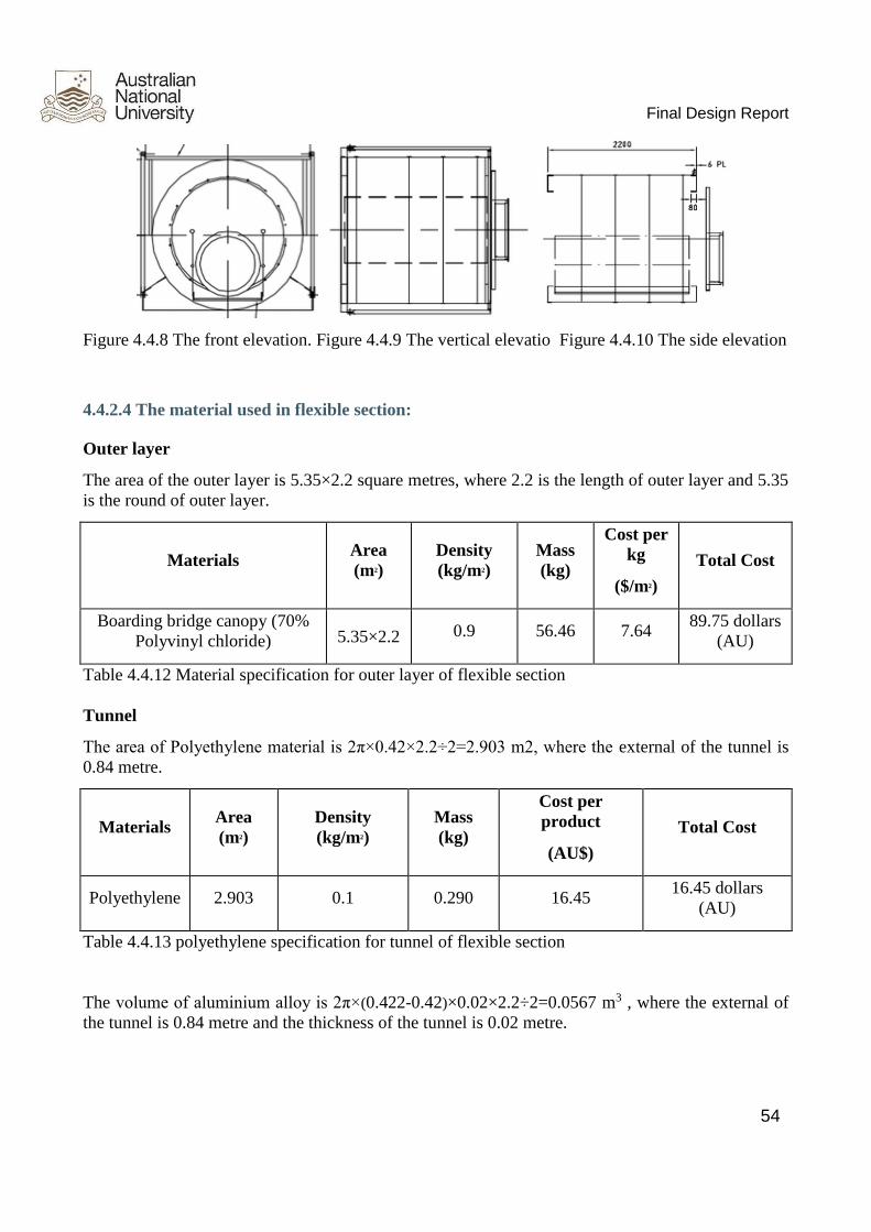
Final Design Report
54
Figure 4.4.8 The front elevation. Figure 4.4.9 The vertical elevatio Figure 4.4.10 The side elevation
4.4.2.4 The material used in flexible section:
Outer layer
The area of the outer layer is 5.35×2.2 square metres, where 2.2 is the length of outer layer and 5.35
is the round of outer layer.
Materials Area
(m2) Density
(kg/m2) Mass
(kg)
Cost per
kg
($/m2)
Total Cost
Boarding bridge canopy (70%
Polyvinyl chloride) 5.35×2.2 0.9 56.46 7.64 89.75 dollars
(AU)
Table 4.4.12 Material specification for outer layer of flexible section Tunnel
The area of Polyethylene material is 2π×0.42×2.2÷2=2.903 m2, where the external of the tunnel is
0.84 metre.
Materials Area
(m2) Density
(kg/m2) Mass
(kg)
Cost per
product
(AU$)
Total Cost
Polyethylene 2.903 0.1 0.290 16.45 16.45 dollars
(AU)
Table 4.4.13 polyethylene specification for tunnel of flexible section The volume of aluminium alloy is 2π×(0.422-0.42)×0.02×2.2÷2=0.0567 m3 , where the external of
the tunnel is 0.84 metre and the thickness of the tunnel is 0.02 metre.

Final Design Report
55
Materials Volume (m3) Density (103kg/m3) Mass (kg) Cost per kg
($/kg) Total Cost
Aluminium alloy 0.0567 2.75 155.925 $2.103/kg 327.91
dollars (AU)
Table 4.4.14 aluminium specification for tunnel of flexible section (Online Metals, 2015) Prop shaft
The prop shaft on both ends of the outer layer:
8 prop shafts, the diameter of each prop shaft is 0.0142875 metre and the length of them is 1.72 metres.
The prop shaft on sides of the outer layer:
12 prop shafts, the radius of each prop shaft is 0.0142875 metre and the length of them is 1.86 metres.
Materials Length
(m) Density (kg/m) Mass (kg) Total Cost($)
Alloy Steel
4140 36.08 1.265 45.64 619.70
Table 4.4.15 Material specification for outer prop shaft of flexible section (ΑΖΟ Materials, 2015)
4.4.3 Docking Module Hatch
There are two kinds of hatches in docking module:

Final Design Report
56
Figure 4.4.11 diagram of two door systems used in docking module
The first kind of door is used to connect the HAB module and the garage module to the docking
module. It is also used in connection of different docking passages. The second kind of door is directly
connected to the flexible extension part.
The door connected to the garage is designed to be in the garage side and open outward to the garage.
In this way, docking passage’s small space will not cause problems to the use of the door and people
can use the door conveniently and safely. This design idea satisfies the requirement A8.2.2 Safety
living equipment. In addition, design of the door connected to the Habitat module is similar to the
discussed one.
The door which connects the main passage and the side passage should be designed in the side passage
side and open inward to the side passage side, so that when opening, the door will not hinder the use
of the main passage especially when there is an emergency condition. Based on same consideration,
the door connected to the extension section is designed to open inward to the passage.

Final Design Report
57
4.4.3.1 Detailed Door Design
Figure 4.4.12 diagram of the two doors
As required, there is a small window on each door except the one connected to the extension section
(for that door, window is on the wall). Each door also has a doorknob so that people can open it. The
mechanism of seal section is the same with the design of our door subsystem group. Thus for a big
door, the length of rubber seal should be 3.66 metres, while for the small door, the length should be
2.52 metres.
4.4.3.2 Material & Budget
In general, materials analysis is consistent with the design of door subsystem.
Parts Chosen Material Density (g/cm3) Mass (kg) Price
Window PMMA 1.18 0.21 ~AUD 10
Rubber seal Synthetic rubber \ \ ~AUD 100
Door Aluminium alloy 2.75 665 ~AUD1500
Table 4.4.16 material specification for door system
4.4.4 Verification

Final Design Report
58
The requirements of the docking module and a description of how verification that the design detailed
above meets these requirements is outlined in the table below.
Verification ID Reqd by Description
V6.1 R6.1 The length of the passage must be 2.2m length. To verify this, the
length of the passage can be measure using a tape measure
V6.2 R6.2 The docking module must be able to hold a weight of 200kg. To
verify this ANSYS modelling of the system can be done. Once the
design has been built it can be verified by loading the system with an
increasing weight until deformation starts to occur and comparing it
to the required 200kg load
V7.0 R7.0 Test the power source from the garage by measurement using
electronic measuring tools. Compare with the target value.
Table 4.4.17 Verification
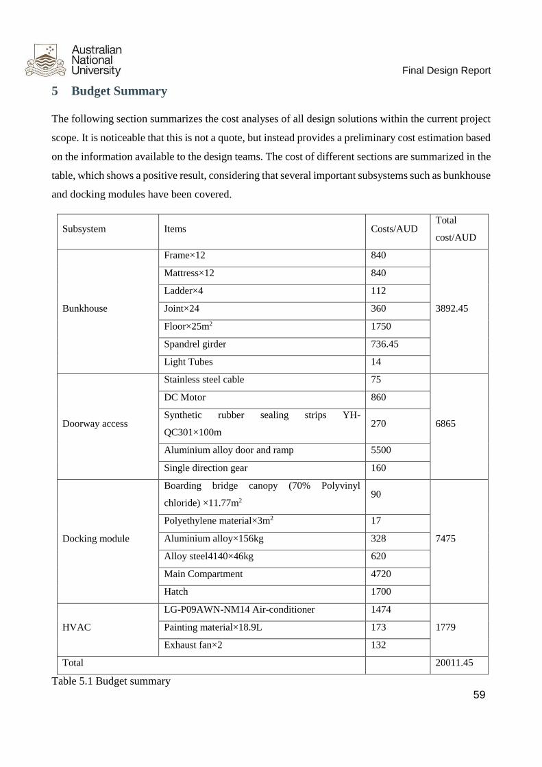
Final Design Report
59
5 Budget Summary
The following section summarizes the cost analyses of all design solutions within the current project
scope. It is noticeable that this is not a quote, but instead provides a preliminary cost estimation based
on the information available to the design teams. The cost of different sections are summarized in the
table, which shows a positive result, considering that several important subsystems such as bunkhouse
and docking modules have been covered.
Subsystem Items Costs/AUD Total
cost/AUD
Bunkhouse
Frame×12 840
3892.45
Mattress×12 840
Ladder×4 112
Joint×24 360
Floor×25m2 1750
Spandrel girder 736.45
Light Tubes 14
Doorway access
Stainless steel cable 75
6865
DC Motor 860
Synthetic rubber sealing strips YH-
QC301×100m 270
Aluminium alloy door and ramp 5500
Single direction gear 160
Docking module
Boarding bridge canopy (70% Polyvinyl
chloride) ×11.77m2 90
7475
Polyethylene material×3m2 17
Aluminium alloy×156kg 328
Alloy steel4140×46kg 620
Main Compartment 4720
Hatch 1700
HVAC
LG-P09AWN-NM14 Air-conditioner 1474
1779 Painting material×18.9L 173
Exhaust fan×2 132
Total 20011.45
Table 5.1 Budget summary

Final Design Report
60
The current total estimated cost will be $20011.45. There are a number of factors that has large
influence on the cost estimation including:
● Quotes from different suppliers
● Labour and installation costs
● Location based costs
● Occupants’ ability to follow equipment protocols
Possible suppliers have been found for each of the materials given above. Additional costs include
the manufacturing cost of the panels. It is important to note that the total cost is a rough estimate and
not a quote. It is recommended that the client seek a full quote from a supplier should they decide to
use this system.
Labour costs may increase or decrease costs depending on the nature of the final design solution.
Currently, the total cost of each subsystem only covers the cost of materials required. The additional
shipping, transportation and installation fees of these materials haven’t been taken into account yet
but they do have an impact on the total cost because of the location of the habitat.
The ability of the residents to follow the equipment protocols can directly affect the cost of the habitat.
Where the crewmembers are improperly or incompletely trained, oversights and accidents can occur
which leads to damage to the systems at considerable expense. For example, improper use of
bunkhouse facilities can lead to damage which would result in costly repair or replacement.

Final Design Report
61
6 Risk analysis
Risk assessment helps to minimise the occurrence and impacts of risks inherent to the project, through
the identification of preventative measures and mitigation strategies. In this part, risks will be
identified first, following with scaled strategy with the help of risk matrix which is shown below.
After that, possible solutions will be provided. In addition, risks in this project are mainly divided
into two parts: management risks and design risks.
Risk matrix used in the assessment:
Likelihood Consequence
Negligible Minor Moderate Major Catastrophic
Rare L L L M M
Unlikely L L M M H
Possible L M M H H
Likely M M H E E
Almost certain M H H E E
Ps: L = low impact; M = medium impact; H = high impact; E = extreme impact
As can be seen from the matrix, the likelihood for each risk is divided into five ranks: rare, unlikely,
possible, likely, and almost certain. Besides, the consequences are also scaled into five levels:
negligible, minor, moderate, and major. The impact of a risk will be assessed combining these two
aspects and the expected potential damage will be indicated.

Final Design Report
62
Here is the project management risk:
Risks Issues at Risk Consequence Likelihood Consequence*Lik
elihood Mitigation Plan
Failure of manager to
lead the team
The project team cannot
operate normally Minor Unlikely L
Set up a substitute manager to help
the project manager
Failure of Team
members on some
tasks
The project will be behind
schedule Moderate Possible M
All members have to give ideas to
others' work
Insufficient time to
meet deadline
The influence of thesis report
and poster will reduce the
available time for those
members
Moderate Possible M
Set sub-deadlines for each small
task. Make sure all small task can
be completed within time limit
Conflict among
group members
Team cannot accomplish the
project efficiently, and provide
a perfect work
Moderate Likely H
Different opinions should be
discussed by all members, and vote
should be taken when situation
getting worse
Misunderstanding
client needs
Waste much time, and go into
the wrong direction Major Likely E
Record every contact with clients
in formal way, and contact to
clients regularly
Table 6.1 team management risk

Final Design Report
63
As for design risk
Risks Issues at Risk Consequence Likelihood Consequence*
Likelihood Mitigation Plan
Lack of knowledge about
outer space or desert
environment
Cannot provide a safe enough
design Moderate Rare M
Read more outer space
materials
Client not satisfied with
the design
The project will be considered
as a failure Moderate Possible M
Response to clients the team's
achievement timely
The connection joint
failing to hold the folding
bed in bunkhouse
The bed is not safe for people
to sleep Minor Possible M
Increase the number of
connection joints for each bed
Outer layer broken when
flexible section is
expanded or compressed
The airtightness will be
unreliable Moderate Possible M
Do regular maintenance and
examination. Be careful when
expanding or compressing this
section
Tunnel in docking module
faiingl to support people People may get hurt Minor Possible M
Do regular maintenance and
examination.

Final Design Report
64
Risks Issues at Risk Consequence Likelihood Consequence*
Likelihood Mitigation Plan
The noise of air
conditioner
People may not be
comfortable, disturbing the rest
or works of staff
Moderate Possible M Choose low noise air
conditioner type
The stainless cables and
electric capstans failing to
provide enough force to lift
up or down the main
garage door and the ramp
due to durability problems
Safety problem, damage to the
metal shell of the garage, and
also have a bad influence on
seal system
Moderate Possible M Do regular maintenance and
examination.
Lack of experience in both
hardware and software for
this project
Cannot produce a satisfied
prototype Major Possible H
Record every contact with
clients in formal way, and
contact to clients regularly
The upper part of the
docking tunnel broken
when flexible section is
expanded or compressed
The airtightness will be
unreliable Moderate Likely H
Do regular maintenance and
examination. Be careful when
expanding or compressing this
section

Final Design Report
65
Risks Issues at Risk Consequence Likelihood Consequence*
Likelihood Mitigation Plan
Deformation of the floor
due to the expansion with
heat and contract with cold
Result in safety problem and
damage to the seal system Moderate Likely H
The installation process
should be careful. Besides,
good HAVC system is
required
Assumptions and ideas are
diverged from reality
Badly influence the quality of
the design Catastrophic Likely E
Contact to clients and tutor
regularly
Low efficacy of quilted
fire retardant fabric
covered on mattress after
long time
Result in safety problem and
damage to the metal shell of the
garage, and also have a bad
influence on HVAC system
Major Almost
certain E Change mattress every 5 years
Durability of the joint
between the main garage
door and the garage
The joint may easy to be
abraded when using due to the
heavy weight of the door and
other external forces
Major Likely E Do regular maintenance and
examination.

Final Design Report
66
Risks Issues at Risk Consequence Likelihood Consequence*
Likelihood Mitigation Plan
Few in the team majoring
in the Material field
This will be a challenge in
building the habitat, because
the team does not have a good
idea about which materials are
suitable for Mars environment
Catastrophic Almost
certain E
Do the searching about
materials from the very
beginning, and make several
members be responsible for
this problem
Table 6.2 Design Risk

Final Design Report
67
7 References
Alibaba, (2015). Folding Fire Escape Rope Ladder - Buy Rope Ladder,Fire Escape Rope
Ladder,Folding Fire Escape Rope Ladder Product on Alibaba.com. [online] Available at:
http://www.alibaba.com/product-detail/Folding-Fire-Escape-Rope-
Ladder_60248141081.html?spm=a2700.7724838.30.75.eCAspT [Accessed 3 Nov. 2015].
Alibaba, (2015). Hot Selling Wholesale Roll Up Mattress - Buy Mattress,Roll Up Foam
Mattress,Roll Up Mattress Bed Mattress Product on Alibaba.com. [online] Available at:
http://www.alibaba.com/product-detail/Hot-selling-wholesale-roll-up-
mattress_60141649445.html?spm=a2700.7724838.30.205.HOIJ4o [Accessed 3 Nov. 2015].
Alibaba, (2015). Latest Factory Best Sale Nature White Dimmable Waterproof 20 Watt T8 Led
Tube Light Freezer - Buy Dimmable Waterproof 20 Watt T8 Led Tube Light Freezer,T8 Led Tube
Light 18w T8-363,T8 Led Tube Light 18w 1200mm Product on Alibaba.com. [online] Available at:
http://www.alibaba.com/product-detail/Latest-Factory-Best-Sale-Nature-
White_60147910185.html?spm=a2700.7724838.30.1.LEHtFD&s=p [Accessed 4 Nov. 2015].
Alibaba, (2015). Outstanding Airtight Rubber Seal For Garage Door - Buy Airtight Rubber
Seal,Rubber Seal For Garage Door,Garage Door Rubber Seal Product on Alibaba.com. [online]
Available at: http://www.alibaba.com/product-detail/outstanding-airtight-rubber-seal-for-
garage_60308017961.html?spm=a2700.7724838.30.71.rYn1iW [Accessed 3 Nov. 2015].
All Things Stainless, (2015). 316: 5mm 7x19 Wire Rope - Per Metre - All Things Stainless Steel.
[online] Available at: http://allthingsstainless.com.au/home/stainless-wire-rope/7x19-stainless-
wire/7x7-stainless-wire-by-the-meter/316-5mm-7x19-wire-rope-per-meter.html [Accessed 3 Nov.
2015].
AluMATTER, (2015). aluMATTER Aluminium v Steel: General. [online] Available at:
http://aluminium.matter.org.uk/content/html/eng/default.asp?catid=217&pageid=2144417130
[Accessed 3 Nov. 2015].
Amesweb, (2015). Column Buckling and Compression Member Design. [online] Available at:
http://www.amesweb.info/CompressionMemberDesign/CompressionMemberDesign.aspx

Final Design Report
68
[Accessed 3 Nov. 2015].
Amesweb.info, (2015). Structural Beam Deflection and Stress Calculators. [online] Available at:
http://www.amesweb.info/StructuralBeamDeflection/BeamDeflectionCalculators.aspx [Accessed
3 Nov. 2015].
Bunnings, (2015). Pine Treated Mgp10 H3 90x45mm 3.0m. [online] Available at:
http://www.bunnings.com.au/pine-treated-mgp10-h3-90x45mm-3-0m_p8421557 [Accessed 3
Nov. 2015].
Castors Galore, (2015). (37) Adjustable / Levelling Up to 500 Kg - Castors Galore. [online]
Available at: http://castorsgalore.com.au/wpcproduct/pg-37-cg-levelling-upto-500-kg/ [Accessed
3 Nov. 2015].
eFunda, (2015). eFunda: Plate Calculator -- Simply supported rectangular plate with uniformly
distributed loading. [online] Available at:
http://www.efunda.com/formulae/solid_mechanics/plates/calculators/SSSS_PUniform.cfm
[Accessed 3 Nov. 2015].
Engineering Toolbox, (2015). Factors of Safety. [online] Available at:
http://www.engineeringtoolbox.com/factors-safety-fos-d_1624.html [Accessed 3 Nov. 2015].
Engineering Toolbox, (2015). Metals and Alloys - Densities. [online] Available at:
http://www.engineeringtoolbox.com/metal-alloys-densities-d_50.html [Accessed 3 Nov. 2015].
Kirschner, J. (2015). How to Select the Best Room Air Conditioner. [online] Josh Kirshner.
Available at: http://www.techlicious.com/how-to/select-the-right-room-air-conditioner/. [Accessed
3 Nov. 2015].
Ltd, A. (2015). How Does Air Conditioning Work | Airconco. [online] Aircondo. Available at:
http://www.airconco.com/how_does_air_conditioning_work. [Accessed 3 Nov. 2015].
Materials, B. and LONG, D. (2015). ALUMINIUM SQUARE TUBE 100mm X 100mm X 300mm
LONG. [online] eBay. Available at: http://www.ebay.com.au/itm/ALUMINIUM-SQUARE-
TUBE-100mm-X-100mm-X-300mm-LONG-/121377621687?hash=item1c42ab86b7 [Accessed 3
Nov. 2015].

Final Design Report
69
Metal Fabricators, (2015). [online] Available at:
http://www.fab.net.au/rapidfab/Aluminium%20Prices.pdf [Accessed 2 Nov. 2015].
My Winh, (2015). PowerTools K5000-P. [online] Available at:
http://www.mywinch.com/Portable/K5P.asp [Accessed 3 Nov. 2015].
Portland Bolt, (2010). Calculating Yield & Tensile Strength - Portland Bolt. [online] Available at:
http://www.portlandbolt.com/technical/faqs/calculating-strength/ [Accessed 3 Nov. 2015].
Scott Metals, (2015). Scott Metals - Products: Sheet Metal: Steel Supplies, Steel Fabrication,
Building Products, Steel Products, Stair Stringers, Steel Posts and Beams, Steel Prices, Brisbane
Steel Supplies, Brisbane Steel Fabrication, Reinforcing Supplies Brisbane, Roofing Supplies
Brisbane.. [online] Available at: http://www.scottmetals.com.au/sheet [Accessed 3 Nov. 2015].
Supplies, O. and Boat, D. (2015). Aluminium 60 mm x 5 mm Round Tube 6060-T5 Bar Car Part
Welding Boat. [online] eBay. Available at: http://www.ebay.com.au/itm/Aluminium-60-mm-x-5-
mm-Round-Tube-6060-T5-Bar-Car-Part-Welding-Boat-/301754541055 [Accessed 3 Nov. 2015].
www.alibaba.com, (2015). Q235 Galvanized Steel Grids Grating Floor - Buy Steel Grids Grating
Floor,Galvanized Steel Grating Weight,Steel Grating Weight Product on Alibaba.com. [online]
Available at: http://www.alibaba.com/product-detail/Q235-galvanized-steel-grids-grating-
floor_1515184995.html?spm=a2700.7724857.29.57.IP1gxY [Accessed 4 Nov. 2015].
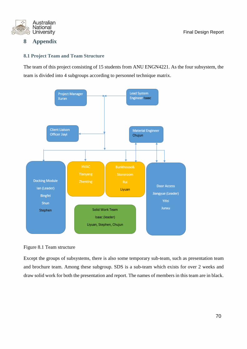
Final Design Report
70
8 Appendix
8.1 Project Team and Team Structure
The team of this project consisting of 15 students from ANU ENGN4221. As the four subsystem, the
team is divided into 4 subgroups according to personnel technique matrix.
Figure 8.1 Team structure
Except the groups of subsystems, there is also some temporary sub-team, such as presentation team
and brochure team. Among these subgroup. SDS is a sub-team which exists for over 2 weeks and
draw solid work for both the presentation and report. The names of members in this team are in black.
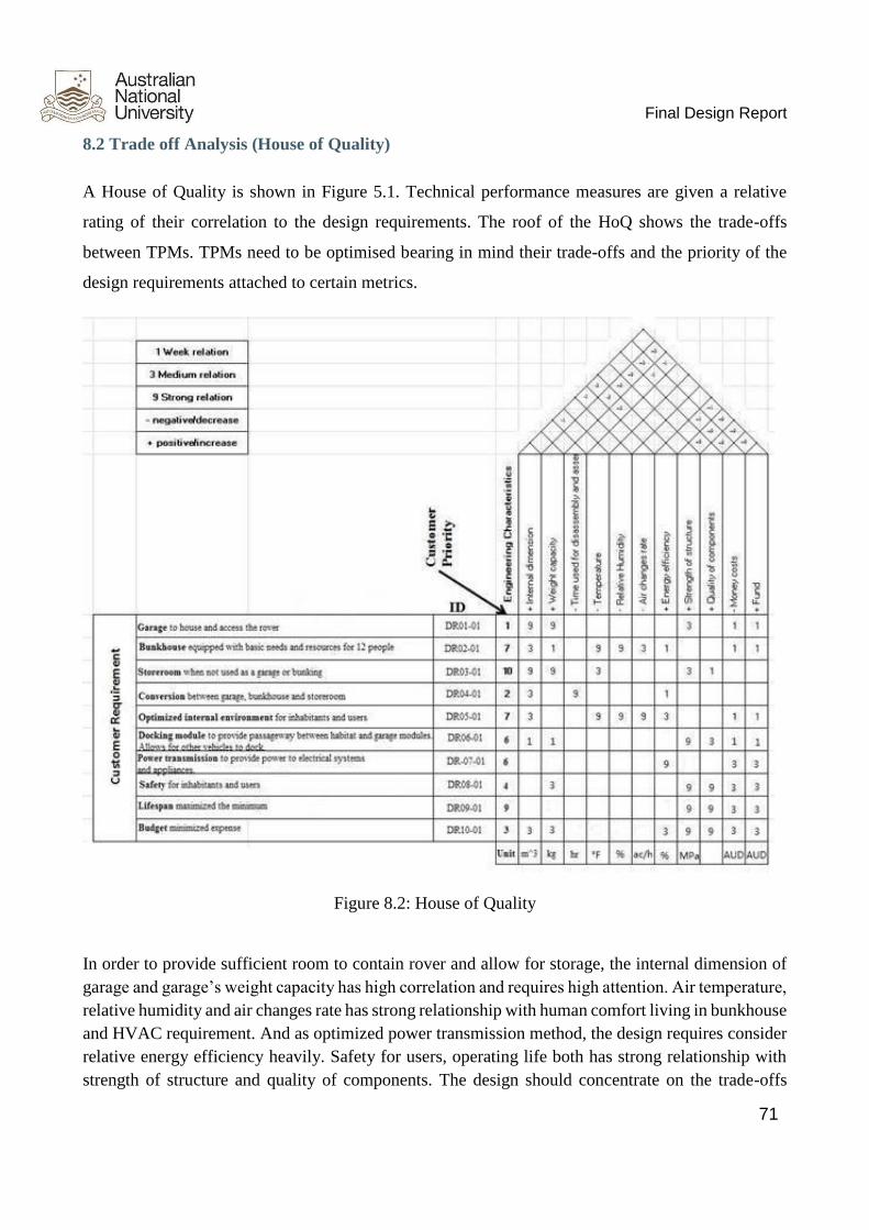
Final Design Report
71
8.2 Trade off Analysis (House of Quality)
A House of Quality is shown in Figure 5.1. Technical performance measures are given a relative
rating of their correlation to the design requirements. The roof of the HoQ shows the trade-offs
between TPMs. TPMs need to be optimised bearing in mind their trade-offs and the priority of the
design requirements attached to certain metrics.
Figure 8.2: House of Quality
In order to provide sufficient room to contain rover and allow for storage, the internal dimension of
garage and garage’s weight capacity has high correlation and requires high attention. Air temperature,
relative humidity and air changes rate has strong relationship with human comfort living in bunkhouse
and HVAC requirement. And as optimized power transmission method, the design requires consider
relative energy efficiency heavily. Safety for users, operating life both has strong relationship with
strength of structure and quality of components. The design should concentrate on the trade-offs

Final Design Report
72
between internal dimension, weight capacity and energy efficiency. Since increase internal dimension
or weight capacity will decrease the energy efficiency performance.

Final Design Report
73
8.3 System Cascade
The table of system cascade displaying two levels of derived attributes are shown below
Primary Attribute Secondary
Attribute Tertiary Attribute Related Subsystems and Interfaces
A1.0 Use as a garage A1.1 Rover housing A1.1.1 Space efficient bunkhouse system BHS/ROV/GAR
A1.1.2 Space efficient docking module system DOC/ROV/GAR
A1.1.3 Space efficient garage door system GAD/ROV/GAR
A1.1.4 Weight capacity (4000kg) GAR/ROV
A1.1.5 Garage internal structural design GAR/ROV
A1.2 Convertible to
garage A1.2.1 Collapsible bunk beds BHS
A1.2.2 Stow-able bunkhouse facilities BHS

Final Design Report
74
Primary Attribute Secondary
Attribute Tertiary Attribute Related Subsystems and Interfaces
A1.2.3 Manually convertible by station personnel BHS/USER
A1.3 Drivable in and
out A.1.3.1 Sufficient ramp weight capacity GAD/ROV/GAR
A1.3.2 Ramp incline angle GAD
A1.3.3 Ramp positioning in-line with housed rover GAD/ROV/GAR
A.1.3.4 Efficient ramp deployment mechanism GAR/GAD
A1.3.5 Space for maintenance and repairs GAR/BHS/ROV
A1.3.6 Space for vehicle entry and exit GAD/GAR/BHS
A2.0 Use as a bunkhouse A2.1 Basic living
conditions A2.1.1 Accommodate 12 people BHS/GAR

Final Design Report
75
Primary Attribute Secondary
Attribute Tertiary Attribute Related Subsystems and Interfaces
A2.1.2 Air ventilation and climate control HVAC/GAR
A2.1.3 Foldable bunk beds BHS/GAR
A2.2 Convertible to
storeroom A2.2.1 Eight hours maximum conversion time BHS/GAD/USER/HAB/DOC
A2.2.2 Manually convertible by station personnel BHS/GAD/USER/HAB/DOC
A2.2.3 The frame of bunk bed could be used as a shelf BHS
A2.3 Convertible to
garage A2.3.1 Eight hours maximum conversion time BHS/GAD/USER/HAB/DOC
A2.3.2 Manually convertible by station personnel BHS/GAD/USER/HAB/DOC
A2.3.3 Foldable bunk bed frame BHS

Final Design Report
76
Primary Attribute Secondary
Attribute Tertiary Attribute Related Subsystems and Interfaces
A2.4 Living
equipment A2.4.1 150kg bunkbed maximum load BHS
A2.4.2 Mattress removable for conversion BHS
A2.4.3 Appropriate mattress size BHS/DOC/HAB
A3.0 Use as storeroom A3.1 Convertible to
bunkhouse A3.1.1 Eight hours maximum conversion time BHS/GAD/USER/HAB/DOC
A3.1.2 Manually convertible by station personnel BHS/GAD/USER/HAB/DOC
A3.2 Convertible to
garage A3.2.1 Eight hours maximum conversion time BHS/GAD/USER/HAB/DOC
A3.2.2 Manually convertible by station personnel BHS/GAD/USER/HAB/DOC
A3.3 Storage
condition A3.3.1 Around 180kg frame maximum load BHS
A3.3.2 Good ventilation to prevent the goods from decay BHS/GAD/HVAC/DOC

Final Design Report
77
Primary Attribute Secondary
Attribute Tertiary Attribute Related Subsystems and Interfaces
A3.3.3 Door should be airtight to prevent the sands from going in BHS/GAD/HVAC/DOC
A3.3.4 Keep the room dry to protect from mould BHS/GAD/HVAC/DOC
A4.0 Comfort A4.1 Proper
temperature A4.1.1 Keep the temperature around 26°C HVAC/POW/GAD/ENV
A4.2 Proper air
pressure A4.2.1 The pressure in the room shall be at around 101 kPa HVAC/POW/GAD/ENV
A4.3 Proper airflow
rate A4.3.1 Keep the airflow rate around 385 m3/h HVAC/POW/GAD
A4.4 Proper
humidity A4.4.1 Keep the humidity in the room at around 50% HVAC/GAD/POW/ENV
A5.0 Convertible A5.1 Ease of
conversion A5.1.1 Reduce required resources BHS/GAD/ROV/USER/HVAC
A5.1.2 Reduce required manpower BHS/GAD/ROV/USER/HVAC
A5.1.3 Reduce man-hours USER/BHS

Final Design Report
78
Primary Attribute Secondary
Attribute Tertiary Attribute Related Subsystems and Interfaces
A5.1.4 Reduce complexity USER/BHS
A5.2 Cost of
conversion A5.2.1 Manual conversion (Cost over time) BHS/USER
A5.2.2 Conversion infrastructure (Initial cost) BHS/USER
A6.0 Docking module A6.1 Capacity to
accommodate
staff/facility
A6.1.1 Accommodate up to 8 people DOC/ENV/USER
A6.1.2 Accommodate up to 800kg weight DOC/ENV
A6.1.3 Strong metal legs to support DOS/ENV
A6.2 Sufficient
power supply A6.2.1 Equipped with 2 LED lights POW/DOC/HAB
A6.2.2 Set consuming power to 20W POW/DOC/HAB

Final Design Report
79
Primary Attribute Secondary
Attribute Tertiary Attribute Related Subsystems and Interfaces
A6.3 Effective
connection with
other parts
A6.3.1 Safety airlock connected to the garage and the outside DOS/ENV
A6.3.2 Flexible section connected to rover DOS/ROV
A7.0 Power transmission A7.1 Reliable
transmission rate A7.1.1 Cable length HAB/USER
A7.1.2 Clear wiring of cables HAB/USER
A7.2 Easy to
transmit and receive A7.2.1 Compatible with various appliances HAB/USER/GAD
A7.2.2 Reliable connection ports HAB/USER/GAD
A7.3 Safety limit A7.3.1 Automatic outage when overloading ENV/GAD/POW
A7.3.2 Connection points covered with insulated rubber POW

Final Design Report
80
Primary Attribute Secondary
Attribute Tertiary Attribute Related Subsystems and Interfaces
A8.0 Safety A8.1 Safety for the
rover A8.1.1 garage door GAD/ROV
A8.1.2 Internal structural design ENV/ROV
A8.1.3 Extinguishing System ROV/HVAC/DOS/GAD
A8.2 Safety for
human A8.2.1 Effective airlock DOS/GAD/USER/ENV
A8.2.2 Safety living equipment BHS/USER/HVAC
A8.2.3 Power safety issue GAD/BHS/DOS/HVAC
A8.2.4 Emergency exit GAD/DOS/USER
A9.0 Lifespan A9.1 Docking
system A9.1.1 Backup Lights available ( LED lights) DOS/HAB
A9.1.2 Durable passageway lasting for at least 5 years DOS/HAB

Final Design Report
81
Primary Attribute Secondary
Attribute Tertiary Attribute Related Subsystems and Interfaces
A9.2 Garage door A9.2.1 Strong ramp lasting for at least 5 years GAD/ROV
A9.2.2 Sturdy main door lasting for at least 5 years GAD/ROV
A9.3 HVAC system A9.3.1 Heating and cooling system lasting for at least 5 years HVAC/USER/ENV/HAB
A9.3.2 Ventilation system lasting for at least 5 years HVAC/USER/ENV/HAB
A9.4 Bunkhouse
system A9.4.1 Safety bed lasting for at least 5 years BHS/USER
A9.4.2 Major equipment lasting for at least 5 years BHS/USER/HAB
A9.4.3 Backup minor equipment available BHS/HAB/DOC/GAD
A10.0 Budget A10.1 Cost of
modelling the design A10.1.1 Simple modelling on computer GAD/BHS/HVAC/DOS
A10.1.2 Actual prototype (low cost) GAD/BHS/HVAC/DOS

Final Design Report
82
Primary Attribute Secondary
Attribute Tertiary Attribute Related Subsystems and Interfaces
A10.2 Cost of
building actual
garage
A10.2.1 Low building cost GAD/BHS/HVAC/DOS
A10.2.2 Low maintenance and repair cost GAD/BHS/HVAC/DOS/ENV/TOS
A10.2.3 Cost for instruments ----
Table 8.3: System cascade showing two levels of qualitative attributes
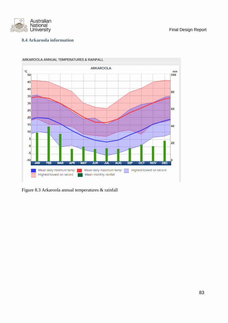
Final Design Report
83
8.4 Arkaroola information
Figure 8.3 Arkaroola annual temperatures & rainfall
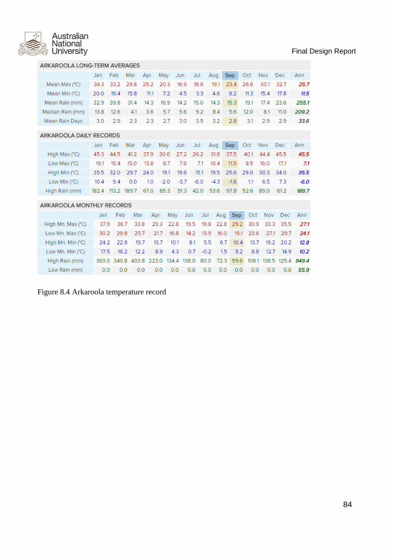
Final Design Report
84
Figure 8.4 Arkaroola temperature record

Final Design Report
85
8.5 Past work diagram
Figure 8.5 Past design diagram
8.5 Price of paint
List of price and sealers:
Material name Price
#10 Chalk Locker 1 Gallon: $21.95 ...5 Gallon: $109.75
#14 Insulating Primer 1 Gallon: $34.50...5 Gallon: $172.50
#15 Aqua-Prime 1 Gallon: $39.50...5 Gallon: $197.50
#16 Stain-Blocker 1 Gallon: $32.95...5 Gallon: $164.75
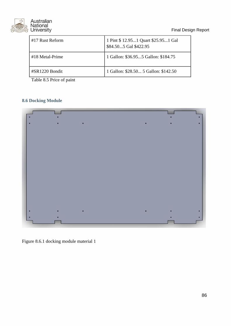
Final Design Report
86
#17 Rust Reform 1 Pint $ 12.95...1 Quart $25.95...1 Gal
$84.50...5 Gal $422.95
#18 Metal-Prime 1 Gallon: $36.95...5 Gallon: $184.75
#SR1220 Bondit 1 Gallon: $28.50... 5 Gallon: $142.50
Table 8.5 Price of paint
8.6 Docking Module
Figure 8.6.1 docking module material 1

Final Design Report
87
Figure 8.6.2 docking module material 2

Final Design Report
88
Figure 8.6.3 docking module material 3

Final Design Report
89
Figure 8.6.4 docking module material 4