Embed Size (px)
Citation preview

Final Design Report
Baja SAE eCVT Mechanical Design
Cal Poly Racing
August 2019
Will Antes [email protected]
Matthew Balboni [email protected]
Benjamin Colard [email protected]
Tyler Connel [email protected]
Julian Finburgh [email protected]

2
Statement of Disclaimer
Since this project is a result of a class assignment, it has been graded and accepted as
fulfillment of the course requirements. Acceptance does not imply technical accuracy or
reliability. Any use of information in this report is done at the risk of the user. These risks may
include catastrophic failure of the device or infringement of patent or copyright laws. California
Polytechnic State University at San Luis Obispo and its staff cannot be held liable for any use or
misuse of the project.

3
Table of Contents
Statement of Disclaimer 2
Table of Contents 3
Table of Figures 6
Table of Tables 8
1. Introduction 9
2. Background 9
2.1 Competition 12
2.2 Regulations 14
3. Objectives 16
3.1 Problem Statement 16
3.2 Customer Specifications 16
3.3 Boundary Diagram 17
3.4 Quality Function Deployment 17
3.5 Engineering Specifications 18 3.5.1 Measurement of Each Specification 20 3.5.2 High Risk Specifications 21
4. Concept Design Development 21
4.1 Single versus Dual Actuation Plan 21
4.2 Failure Mode Analysis 22
4.3 Force Analysis 23
4.4 Actuation Concepts 24 4.4.1 Rigid Arm Actuation Method 24 4.4.2 Pivoting Arm Actuation Method 25 4.4.3 Planetary Gear Set Actuation Method 26 4.4.4 Lead Screw Actuation Method 28
4.5 Selection Process 28
5. Final Design 31
5.1 Final System Design 31 5.1.1 Ratio and Geometric Considerations 32 5.1.2 Sheaves and Belt 36 5.1.3 Shafts 42 5.1.4 Lead Screw 46 5.1.5 Arms 49

4
5.1.6 Case 51 5.1.7 Stiffener Ribs 53 5.1.8 Pivot Points and Shift Forks 56 5.1.9 Bearings 57 5.1.10 Lead Screw Bearing Housings 61
5.2 Meeting Design Specifications 61
5.3 Safety, Maintenance, and Repair Considerations 62
5.4 Detailed Cost Analysis 62
6. Manufacturing 64
6.1 Sheaves 64
6.2 Shafts 65
6.3 Shift Fork 66
6.4 Arms 67
6.5 Waterjet Components 68
6.7 Drive Bushings 68
6.8 Case 69
6.9 Leadscrew 70
6.10 Assembly 71
7. Design Verification 74
8. Project Management 75
8.1 Communication 76
8.2 Lessons Learned 76
9. Conclusion 77
10. References 78
11. Appendices 79
11.1 Quality Function Deployment (QFD) 79
11.2 Concept Selection Decision Matrix 80
11.3 Table of Failure Modes 81
11.4 Preliminary Analysis and/or Testing Details 82
11.5 Concept Drawings 82
11.6 Drawing Package 84
11.7 Bill of Materials/Hardware Order 100

5
11.8 DFMEA 102
11.8 Design Verification Plan 104

6
Table of Figures FIGURE 1. BASIC BELT DRIVEN CONTINUOUSLY VARIABLE TRANSMISSION FUNCTIONALITY [1]..................... 10 FIGURE 2. 3D MODEL SIMILAR TO A GAGED CVT, PRIMARY ON THE LEFT, SECONDARY ON THE RIGHT [2]. 11 FIGURE 3. TABLE OF TUNING INSTRUCTIONS FOR A GIVEN OBJECTIVE. .......................................................................... 12 FIGURE 4. BOUNDARY DIAGRAM FOR THE MECHANICAL DESIGN OF AN ECVT. ........................................................... 17 FIGURE 5. FREE BODY DIAGRAM OF SECONDARY SHEAVE. ...................................................................................................... 23 FIGURE 6. RIGID ARM ACTUATION CONCEPT. .................................................................................................................................. 24 FIGURE 7. PIVOTING ARM CONCEPT. ..................................................................................................................................................... 25 FIGURE 8. PLANETARY GEAR SET ACTUATION CONCEPT. ......................................................................................................... 26 FIGURE 9. LEAD SCREW ACTUATION CONCEPT. ............................................................................................................................. 28 FIGURE 10. FINAL SYSTEM DESIGN. ....................................................................................................................................................... 31 FIGURE 11. BELT CONSTRUCTION. ......................................................................................................................................................... 32 FIGURE 12. SHEAVE GEOMETRY. ............................................................................................................................................................. 33 FIGURE 13. CVT RATIO VERSUS SHIFTING TRAVEL. ...................................................................................................................... 34 FIGURE 14. SHEAVE GEOMETRY SOLIDWORKS SKETCH. ........................................................................................................... 35 FIGURE 15. BELT MISALIGNMENT. ......................................................................................................................................................... 39 FIGURE 16. CVT RATIO VERSUS SHIFTING TRAVEL. ...................................................................................................................... 40 FIGURE 17. BELT MISALIGNMENT GRAPH. ........................................................................................................................................ 41 FIGURE 18. (A) GAGED ENGINEERING PRIMARY SHAFT. (B) GAGED ENGINEERING PRIMARY DRIVE
BUSHING. ................................................................................................................................................................................................... 43 FIGURE 19. GAGED ENGINEERING SECONDARY SHAFT. ............................................................................................................. 44 FIGURE 20. BALL SPLINE CONCEPT........................................................................................................................................................ 44 FIGURE 21. SAMPLE BALL SPLINE AVAILABLE AT MCMASTER. ............................................................................................. 45 FIGURE 22. FINAL SHAFT DESIGN. .......................................................................................................................................................... 46 FIGURE 23. LEAD SCREW SPECIFICATIONS........................................................................................................................................ 47 FIGURE 24. LEAD SCREW AND MOTOR SHAFT INTERFACE. ..................................................................................................... 48 FIGURE 25. SET SCREW SIZING CHART. ............................................................................................................................................... 49 FIGURE 26. NEW BOLTED CONNECTIONS AND BRACE. ............................................................................................................... 50 FIGURE 27. FINAL CASE DESIGN. ............................................................................................................................................................. 52 FIGURE 28. FINAL DESIGN CONCEPT WITH MOUNTING RIBS SHOWN IN ASSEMBLY VIEW. .................................. 54 FIGURE 29. OLD BACKING PLATE MOUNTING CONCEPT SHOWN IN ASSEMBLY VIEW. ............................................ 54 FIGURE 30. PRIMARY AND SECONDARY RIBS. .................................................................................................................................. 55 FIGURE 31. CUTAWAY OF PRIMARY ASSEMBLY. ............................................................................................................................. 58 FIGURE 32. BALL TRANSFER ROLLERS................................................................................................................................................. 60 FIGURE 33. LEAD SCREW BEARING CUP. ............................................................................................................................................. 61 FIGURE 34. FINISHED PRIMARY FIXED SHEAVE WITH BROACHED KEYWAY. ................................................................ 64 FIGURE 35. FINISHED SET OF MOVING SHEAVES. .......................................................................................................................... 65 FIGURE 36. SHIFT FORK AFTER CNC OPERATIONS, STILL REQUIRES HOLES DRILLED AND TAPPED ON
ENDS. ........................................................................................................................................................................................................... 66 FIGURE 37. MACHINING OPERATION #1 ON SECONDARY ARMS. .......................................................................................... 67 FIGURE 38. FINISHED ARMS. ...................................................................................................................................................................... 67 FIGURE 39. FINISHED PIVOTS. .................................................................................................................................................................. 68 FIGURE 40. FINISHED LEAD NUT CARRIER. ....................................................................................................................................... 68 FIGURE 41. (A) SECONDARY DRIVE BUSHING AFTER OPERATION #1. (B) FINISHED DRIVE BUSHINGS. ......... 69 FIGURE 42. LEADSCREW END MACHINING IN PROGRESS.......................................................................................................... 70 FIGURE 43. FULL ASSEMBLY WITHOUT CASE OR BELT. ............................................................................................................. 72

7
FIGURE 44. SECOND ANGLE OF ASSEMBLED ECVT. ....................................................................................................................... 73

8
Table of Tables TABLE 1. SIMILAR PRODUCTS ON THE MARKET............................................................................................................................. 13 TABLE 2. RULES FROM 2018 BAJA SAE RULES PERTAINING TO THE CVT. ....................................................................... 15 TABLE 3. LIST OF WANTS AND NEEDS OF OUR CUSTOMER. ..................................................................................................... 16 TABLE 4. ENGINEERING SPECIFICATIONS FOR THE ELECTRONICALLY-CONTROLLED CVT................................... 18 TABLE 5. MEASUREMENT OF EACH SPECIFICATION. ................................................................................................................... 20 TABLE 6. POTENTIAL FAILURE MODES................................................................................................................................................ 22 TABLE 7. BELT AND SHEAVE DESIGN DECISIONS........................................................................................................................... 37 TABLE 8. COST REPORT ANALYSIS. ........................................................................................................................................................ 63 TABLE 9. MANUFACTURING ANALYSIS. ............................................................................................................................................... 74

9
1. Introduction
This objective of this project was to design, manufacture, and test the mechanical systems of an
electronically-controlled continuously variable transmission (eCVT) for the Cal Poly Baja SAE
vehicle. Our group had a sister group responsible for the controls involved with a functioning
eCVT. This report will focus on the mechanical design, conducted by a team of five students. The
Cal Poly Baja SAE team designs, builds, and competes with a 10hp spec-class off-road race
buggy each year. The car currently uses a Gaged Engineering GX9 mechanical CVT to connect
the engine to the final drive at varied ratios to efficiently transfer power. This project aims to
replace the Gaged Engineering GX9 CVT with an electronically-controlled CVT that is more suited
to our car and the competition. The GX9 CVT is expensive, heavy, difficult to tune quickly, parts
are difficult to source, has a limited range of operable final drive ratios, and cannot be effectively
tuned between events due to competition rules. The goal of this project is to address these
problems with a prototype eCVT for the Baja team to test before the 2020 competition season.
This final design report will include design changes made since our critical design report,
manufacturing documentation, testing results, project management, and recommendations for the
future. Many sections have carried over from our previous critical design report but have been
altered where necessary. There are some key changes since CDR, and these changes are
reflected in the final design section. The detailed design section outlines the reasoning for our
design decisions, and it shows how our engineering specifications are met. The manufacturing
plan explains in depth how we planned to make each part. Similarly, the project management
section shows differences between the Gantt chart that was updated at CDR and the actual post-
CDR project management. Conclusions and recommendations are included to both demonstrate
our team’s growth and learning experiences, and to allow future teams to profit from our work.
2. Background
The Baja team uses a continuously variable transmission to efficiently transfer power from the
mandated stock Briggs and Stratton Model 10 Intek engine. This engine has a narrow power
band, and any deviation from that power band causes significant performance losses. A CVT
allows the engine to remain in its power band while still shifting through its entire range of ratios.
There are many different CVT designs, ranging from more complex hydrostatic or toroidal
machined surfaces to change the power transmitting radii, to more traditional belt and pulley
systems. The common thread is that they are all able to smoothly shift through infinitely many
gear ratios, between a maximum and minimum. Due to our manufacturing, time, and budget
constraints, we will focus on improving and optimizing the basic mechanical belt and pulley
system. Fortunately, this simpler design has proven to be a rugged, reliable, and easily adjustable
solution and is currently employed by most Baja teams.

10
The basic function of the mechanical CVT is based on a pair of angled pulleys, each clamping a
semi-flexible V-belt. The belt transmits the power from the driven (primary) pulley mounted on the
engine crankshaft, to the driven (secondary) pulley mounted on the gearbox input shaft. Each
pulley consists of two sheaves, one of which is free to move axially along its respective shaft. By
varying the amount of force applied to a moving sheave, the belt can be made to ride higher or
lower in the pulley. Figure 1 below illustrates the basic relationship.
Figure 1. Basic Belt Driven Continuously Variable Transmission Functionality [1].
The traditional method of applying force to the moving sheave on the primary is through the use
of weights mounted such that increasing engine speed will cause them to swing with increasing
centrifugal force against a cam surface. This causes the primary sheave to close and creates a
higher effective ratio. The secondary moving sheave is typically actuated by torque feedback from
the road. As the vehicle enters conditions of higher load such as a hill or soft sand, the increased
torque feedback causes a helical cam mechanism to twist and close the secondary sheave,
lowering the gear ratio. The increased road load and gearing will in turn begin to drag down the
engine speed, removing centrifugal force from the primary. This reduced centrifugal force will
cause the primary to backshift, which reduces the load on the engine allowing it to spin at its peak
power again. These two actions create a self-adjusting mechanism that will trade speed and
torque based on road conditions and driver input, while keeping the engine at optimal power
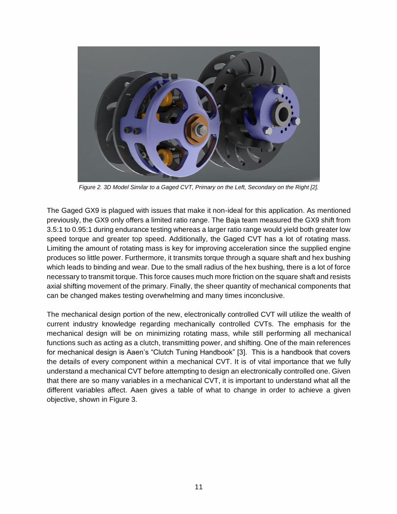
output. Figure 2 below shows a 3D model very similar to the Gaged CVT currently in use. The
centrifugal “flyweights” can be seen in yellow. For peak performance, the actuation of both pulleys
must be delicately tuned by choosing balanced combinations of springs, weights and machined
cam profiles.
11
Figure 2. 3D Model Similar to a Gaged CVT, Primary on the Left, Secondary on the Right [2].
The Gaged GX9 is plagued with issues that make it non-ideal for this application. As mentioned
previously, the GX9 only offers a limited ratio range. The Baja team measured the GX9 shift from
3.5:1 to 0.95:1 during endurance testing whereas a larger ratio range would yield both greater low
speed torque and greater top speed. Additionally, the Gaged CVT has a lot of rotating mass.
Limiting the amount of rotating mass is key for improving acceleration since the supplied engine
produces so little power. Furthermore, it transmits torque through a square shaft and hex bushing
which leads to binding and wear. Due to the small radius of the hex bushing, there is a lot of force
necessary to transmit torque. This force causes much more friction on the square shaft and resists
axial shifting movement of the primary. Finally, the sheer quantity of mechanical components that
can be changed makes testing overwhelming and many times inconclusive.
The mechanical design portion of the new, electronically controlled CVT will utilize the wealth of
current industry knowledge regarding mechanically controlled CVTs. The emphasis for the
mechanical design will be on minimizing rotating mass, while still performing all mechanical
functions such as acting as a clutch, transmitting power, and shifting. One of the main references
for mechanical design is Aaen’s “Clutch Tuning Handbook” [3]. This is a handbook that covers
the details of every component within a mechanical CVT. It is of vital importance that we fully
understand a mechanical CVT before attempting to design an electronically controlled one. Given
that there are so many variables in a mechanical CVT, it is important to understand what all the
different variables affect. Aaen gives a table of what to change in order to achieve a given
objective, shown in Figure 3.

12
Figure 3. Table of tuning instructions for a given objective.
While this does not constitute a comprehensive list, it is a good starting point for an understanding
of a CVT. One of Aaen’s main points in this handbook is a statement he writes in all capital letters
saying, “The main rule of clutch tuning is: if you want to change engine speed, work on the driving
clutch. If you want to improve back-shifting or efficiency, work on the driven clutch” [3]. Engine
speed needs to be tunable to match the power curve of the engine the team is given. The finer
the tunability of the primary, the closer the team can get to optimal shift RPM and the better they
can make use of the engine’s power. Back shifting is important for climbing hills as well as start
and stop driving, both of which the car sees regularly.
2.1 Competition
There are a number of CVTs that currently exist today that are comparable to the product we
intend to make. It is important to understand these products and the decisions that drove their
design in order to make intelligent design choices for our CVT. Some various designs are outlined
in Table 1.

13
Table 1. Similar products on the market
Gaged Engineering GX9 The Gaged Engineering GX9 CVT is mechanically actuated. It
weighs close to 18 pounds.
Michigan Baja Racing CVT [4] Michigan Baja racing uses a bespoke CVT with ratios from
0.75:1 to 4.0:1. Uses adjustable flyweights and is extremely
lightweight.
Cal Poly Pomona eCVT Cal Poly Pomona Baja uses a custom electronically controlled
CVT. The primary inboard face is actuated with a lever arm. Had
low reliability at 2017 competitions. From conversations at the Oregon 2018 competition, they mentioned that they used wheel speed and engine speed as inputs, and that their actuator
was extremely powerful.
Polaris CVT The Polaris CVT is used on their RZR vehicles. Designed for high horsepower applications and is very simple and dust resistant.
Customers are generally tolerant of the product but not happy
Subaru Lineartronic CVT [5] Production electronically controlled CVT used in Subarus. Both primary and secondary are actuated by a hydraulic system. Uses a chain immersed in oil.
Fortunately for our team, mechanical CVTs are relatively common, and there is a fair bit of
literature detailing the clutch design. However, electronically-controlled CVTs are much less
14
common, and those that exist are purpose built for production automobiles and have less in
common with our racing application. Due to this issue, our CVT senior project team has decided
to split into a mechanical design group and a controls and modeling group. We hope that this
division of work may allow us to dedicate enough time to a relatively new product, while still paying
close attention to design and analysis of the mechanical systems. Olav Aaen’s Clutch Tuning
Handbook will serve as a guideline for our mechanical clutch design. Aaen has over 30 years of
experience in snowmobile racing and documents the evolution of CVTs and tuning parameters.
Also, our team has access to multiple papers from other universities that have created CVTs for
their Baja cars. These papers provide the context needed to apply the knowledge we get from the
Clutch Tuning Handbook and apply it to Cal Poly’s 2019 Baja SAE vehicle. A senior project group
from the University of Michigan wrote a paper about the design of a “testing CVT” that was
intended for data collection on the dyno as well as on the car. The paper focused on the design
of a mechanically actuated primary pulley. They considered electronic or hydraulic actuation
however they decided against it due to space constraints and the need for additional power from
the engine or a battery. They used a decision matrix to make a final decision to use flyweights for
actuation. The final concept was a standard mechanical CVT that was lightweight and easy to
manufacture, and it referenced Aaen’s Clutch Tuning Handbook extensively [3].
A student from the University of Akron wrote a master’s thesis about why an electromechanically
actuated CVT can maximize the performance and efficiency of a CVT without using too much
power. It was measured that an electromechanically actuated CVT can transmit 1.2 HP or 17%
more power than an equivalent mechanically actuated CVT in the range of ratios from 3:1 to 3.5:1.
Both methods of actuation were able to provide similar amounts of power throughout the rest of
the range of ratios. The electronic actuation only came at the small price of 0.027 HP needed to
power the actuator. The mechanical CVT used in this experiment was a Comet Industries Model
790, which some Baja SAE teams use for their transmission [6].
Both production CVTs and other Baja team’s custom examples all have different forms of
actuation and levels of control. Some of the most significant unknowns we have had to define as
a group were: which clutches we want to electronically control and how we should actuate them.
In a mechanical CVT, the primary is shifted by the engine speed, and the secondary is shifted by
the road load. If we control both the primary and secondary clutches, we have great control over
the entire system, but now no longer use torque feedback from the road to shift. Though we have
seen other Baja SAE teams control the primary electronically, no teams have actuated the
secondary clutch, let alone both the primary and secondary.
2.2 Regulations
Our team is in a unique position because our product does not have to abide by any industry
codes or regulations other than the Baja SAE rulebook [7]. There are rules pertaining to powertrain
guards, energy storage systems, and following “sound engineering practice”. Each year, a new
rulebook is released with revisions, although rules pertaining to the CVT have not changed in
years and we do not anticipate any large changes. Relevant rules are found in Table 2.

15
Table 2. Rules from 2018 Baja SAE Rules pertaining to the CVT.
B.2.7.15 “The engine may be fitted with an approved alternator to generate electrical power. The only alternators which are permitted are those which Briggs & Stratton specifies for the engine model. Available alternators are sized in 3, 10, and 20 Ampere versions.”
B.9.1 “All rotating powertrain components (CVTs, Gears, Sprockets, Belts and Chains) shall be
shielded to prevent injury to the driver, track workers, or bystanders. Guards shall protect against hazardous release of energy should rotating components fail. Guards shall also protect against fingers, loose clothing, or other items from being entangled in the rotating components (pinch points). Universal joints, CV joints, hubs, rotors, wheels and bare sections of shafts are exempt from the requirements of B.9.1 and B.9.2.”
B.9.2 “Powertrain guards and shields protecting against hazardous release of energy shall extend
around the periphery of the rotating components (chains, gears, sprockets, belts, and CVT’s) and have a width wider than the rotating part the guard is protecting.
Note: This means the entire periphery of the primary CVT pulley, not just the belt width.
All powertrain guards shall be constructed of one or both of the following required materials:
-Steel, at least 1.5 mm (0.06 in.) thick, meeting or exceeding the strength of AISI
1010 steel. Page 68, Revision D – 2018/05/01
-Aluminum, at least 3.0 mm (0.12 in.) thick, meeting or exceeding the strength
of 6061-T6 aluminum.
Holes and or vents in the portion of the powertrain guard surrounding the rotating components are acceptable provided that in the event of a powertrain failure, no parts can escape. No direct path shall exist tangent to any rotating components.
Powertrain guards shall be mounted and secured with sound engineering practices in order to resist vibration and shock.
B.9.3 “Rotating parts in the powertrain system rotating faster than the final drive shall be guarded on all sides, in addition to the guard around the periphery. Guarding for pinch points shall prevent small, searching fingers from getting entrained in any rotating part. Flexible, non-rigid, fabric coverings such as "Frogskin", Ceconite, and neoprene are unacceptable for use as finger guards. Powertrain covers fastened with adhesive, ratcheting tie-downs, and other temporary methods are explicitly prohibited. All powertrain covers shall have resilient and durable mountings with easily accessed and actuated fastening devices.
A complete cover around the engine and drivetrain is an acceptable shield for pinch points but does not relieve the requirement for release of hazardous energy.”
B.10.2 “All vehicle wiring and connectors shall be cleanly and neatly installed. Wiring shall be routed
away from sources of excessive heat, abrasion, chafing, and possible short circuit. Wiring shall be installed and routed such that it does not become a hazard to cockpit egress.”
B.10.6 “Vehicles may be equipped with data acquisition (data logging) systems. Data acquisition systems providing live feedback to the driver or telemetry data to the team must be included in the cost report. Data acquisition systems not providing live data to the driver and/or telemetry data to the team may be excluded from the cost report.”

16
3. Objectives
3.1 Problem Statement
The purpose of the eCVT is to implement an electro-mechanical shifting system to efficiently
transmit the most power from the vehicle’s engine to the wheels at any given speed. By using an
electronically-controlled CVT, we will be able to dictate the final drive ratio based on the selected
tune as well as sensor inputs. The controller should be programmable for different driving
scenarios. The eCVT needs to perform better than the current CVT in terms of time to top speed,
while retaining at least the current top speed of the car. One key factor in improving this
performance is that it needs to have less inertia than the Gaged CVT, particularly in the primary
clutch. It also needs to be more tune-able on the fly than the Gaged. Competition rules dictate
that physical components must remain unchanged throughout the duration of the competition,
which makes changing springs and flyweights for different events impossible with the Gaged.
Therefore, it must be run at a moderate tune to suit the varied events. The eCVT shall be tunable
without replacing components, allowing it to be tailored to each event. Table 3 below covers
important design parameters and their target specifications. Each parameter has a target, a
tolerance for that target, the risk that that target will fail to be met, and the way we will test if that
parameter is on target.
3.2 Customer Specifications
Knowing the customer’s wants and needs will help drive design decisions as well as keep the
team develop specific engineering specifications to ensure that the customer is satisfied and the
product functions as it should. Table 3 lists the desires of our customer, the Baja team.
Table 3. List of wants and needs of our customer.
Customer Needs Customer Wants
Vehicle Speed excess of 35 mph Vehicle Speed approaching 45 mph
Do not exceed current CVT weight Reduce weight if possible
Manufacturability - Most parts to be made in house
Manufacturability - ALL parts to be made in house with the exception of splines
Temperature - Must keep internal temperature near 180℉
Internal temperature <180℉
Weather Resistance - IP54 Standard Case
Serviceability - Must be able to tune CVT and/or replace CVT at a fast pace
Be able to fix most CVT problems trackside, preferable under 5 min, with no custom tools
Components with shorter design life (Belt, Components with shorter design life must be

17
etc.) must have life cycle >60 hrs. easily replaceable
Reliability - Must be able to have consistent performance race after race.
Design and components must adhere to SAE BAJA rules and regulations
Project must remain within budget-TBD
Design must ensure human safety
3.3 Boundary Diagram
This boundary diagram distinguishes deliverables for this project from other aspects of the car
they will interact with that come from other sources. The two clutches, the belt, the actuation
mechanism, the case and cover, and the engine alternator are all within the scope of this project.
The actuators, microcontroller, model, and software will all come from the Controls Crew senior
project. The Baja car, engine, and gearbox will all come from the Baja team.
Figure 4. Boundary diagram for the mechanical design of an eCVT.
3.4 Quality Function Deployment
Quality Function Deployment (QFD) is an exercise used to develop engineering specifications for
the project. The end result is a called a House of Quality, and it outlines all of the factors taken
into account for the QFD. Our House of Quality is included in Appendix A. The QFD started off by
identifying who were our customers and listing them in the “Who” section. Our three main

18
customers are the driver, the Baja team’s CVT Lead, and the Baja team’s Manufacturing Lead.
We developed a list of customer needs and listed them in the “What” section. These needs were
then given a rank of importance for the three customers. We then created a list of qualitative
engineering goals and listed them in the “How” section. These were compared to the customer
needs and each comparison was given a rank from not correlated to strongly correlated. This led
to us choosing numerical engineering specifications in the “How Much” section. They were ranked
in terms of relative importance based on our previous correlations. The most important
specifications according to our House of Quality are the 60-hour design life, five minutes to change
tune, and 35 mph top speed. When compared to our competitors in the “Now” section this CVT
would beat or match the performance of every other competitor if these specifications are met.
3.5 Engineering Specifications
Table 4. Engineering Specifications for the Electronically-Controlled CVT.
Spec # Parameter Description
Requirement or Target (units)
Tolerance Weight Compliance Notes
1 Ratio Range 4:1 to 0.75:1 +/- 15% High Test, Analysis Still under consideration
2 Tunability in competition
Different tunes for each event
Min High Analysis, Inspection
Typical to change tunes
between events
3 Belt Temperature 180 ℉ +/- 10% Medium Testing Past temperature
data
4 Weight 20 lb Max Medium Analysis, Inspection, Compare
5 Design life 20 hours Min Medium Testing Typical season length
6 Weather Resistance IP54 Standard Min Medium Testing No submersion present at
competition
7 Manufacturability 90% in house +/- 10% Low Inspection Need ability to make spares
easily
8 Cost to Team $1000 +/- 25% Low Inspection Set by sponsor
9 Cost Report Cost $1225 Max Low Inspection The GX9 cost $1225
We constructed our engineering specifications with performance, reliability, and practicality in
mind, in this order. With respect to performance, we wanted to mandate a window of ratios and

19
ensure easy access to tune in the field. The range of ratios we chose above, 4:1 to 0.75:1 was
chosen based on what most competitive Baja SAE teams run for their CVT ratios. Additionally,
since the primary must fit over the engine shaft, the minimum diameter is limited, and since the
secondary cannot get too large without hitting the car’s CV joints and floor, the low ratio cannot
get much lower than 4 without compromising efficiency due to a small belt radius.
The goal for on-the-fly tuning for the eCVT is that the team members can change the CVT tune
to different event-specific settings without any tools, during competition, while meeting all
competition rules. The rules dictate that no physical parts on the car can be changed for different
ones. Thus, the tuning must be changed purely electronically or by moving the position of
springs/switches/selectors.
The operating range of our eCVT must remain within the spec of the belt and the electronic
components. We know from testing with our Gaged CVT that rubber belts begin to break down
around 195℉. Additionally, if the belt is too cold it will slip excessively, causing poor performance.
180℉ is the optimal operating point of the belt.
The current Gaged GX9 with a belt weighs about 18 pounds. In order to improve acceleration
performance, we need to lower the inertia of the CVT. As such, our overall weight limit for the
eCVT is 20 pounds, with the caveat that inertia of the system should decrease, even if the overall
weight stays the same. We recognize that the actuators will add some weight, which is why the
goal is not necessarily to reduce the overall system weight.
Through documentation of last year’s competition and testing season, we have found that the
Baja car sees about 20 hours of running time per year. As such, we want to design all wear
components of our eCVT to last for 20 hours. Based on the Gaged, we would like to see at least
a 10-hour belt life, though that is very difficult to predict and will need to be tested to validate.
The Baja car sees intense environmental conditions in testing and at competition. It drives through
mud, sand, dust, and water crossings. To protect the eCVT components from water and dust
damage, the case must meet or exceed IP54 standards. That means that it is dust resistant
enough to ensure performance and water resistant to splashing from all directions.
For manufacturability, 90% or more of the parts shall be made at Cal Poly. Achieving this goal will
reduce costs and lead times and improve quality control.
The cost to the team shall be less than $1000 for the eCVT, to remain competitive with the Gaged
and stay in budget. Lastly, for the cost report event, the Gaged is $1225 by rules, so the eCVT
should cost less than $1225. Cost report cost is calculated according to a specific formula from
the SAE competition.

20
3.5.1 Measurement of Each Specification
All engineering specifications must be specific and measurable. As such, it is important to have a
plan in place to measure whether our design has met all of our design specifications. Table 5
details a plan for validation of each of our specifications.
Table 5. Measurement of Each Specification.
Ratio Range Hall effect sensors will be used to obtain angular velocity of both the primary and secondary clutches. Position of actuators will provide us with sheave position so we may solve for belt slip error.
Tunability Measure the time it takes to switch tunes. Car must start test driving in one tune, come to a complete stop, shut off the engine, change the tune, and continue driving with a second tune. Timer will begin when the car stops, and end when the cars moves.
Belt Temperature Correlate case or sheave temperature to belt temperature through experimental data. We can measure temperature with temperature labels which indicate a certain temperature has been exceeded.
Weight We will weigh the entire system with a calibrated scale. We will include both clutches, the belt, actuators, alternator, wiring, controllers, sensors, etc. Everything needed to make the eCVT run will be included in the weight.
Design Life We will test the eCVT on the car during an entire Baja test season, which is about 20 hours of off-road driving time in varied environments. We will measure belt wear by inspecting the belts before each testing day. Sheave wear will be done by inspection of the faces. The wear of other components will be either measured by CMM or by manual measurement techniques if the geometry permits.
Weather Resistance
IP54 standard dictates that spray from any direction may not enter the enclosure. We will spray a household hose at the case from all angles. Once the entire outside of the case is wet, we will inspect the inside for any water.
Manufacturability At least 90% of the parts should be able to be produced in-house by students. This greatly reduces lead time on components, increases student learning, and helps keep up the spirit of the competition.
Cost We will pay close attention to money spent on prototyping efforts and final production. The $1,000 budget applies to final production only.

21
3.5.2 High Risk Specifications
The highest risk specifications are the mass of the system and the tune-ability. The mass is a
high risk at this stage because we are unsure of how much actuation force we will need, which
will dictate size and mass of the actuator(s). Additionally, at this stage of design we have not
analyzed how much mass can be safely removed from the GX9 as a benchmark. The main goal
for the mass of the system is to reduce rotating mass, and the risk of not reducing rotating mass
is much lower than the risk of increasing overall mass of the system. This is because most likely
the actuators will not rotate with the clutch(es). The second high-risk specification is that the eCVT
will not be fully tunable on the fly. This is largely up to the Controls team to create a functioning
and intuitive GUI for the tuning of the system. This may be difficult due to competition rules about
cost. Additionally, we may find that programming changes alone do not sufficiently change the
tune, and that physical components must be changed (i.e. springs, helixes, sheaves) to achieve
the optimal tune for each event.
4. Concept Design Development
Early in the design period, the team conducted multiple brainstorming sessions, generating
concepts for methods to actuate the sheaves in and out. Different actuation power sources were
researched, with primary consideration of either hydraulics, pneumatics or an electric motor.
Electronically controlled actuators were immediately chosen over pneumatic or hydraulic
operated actuators due to a number of factors. The main reason pneumatic and hydraulic
controllers were ruled out was due to the additional equipment needed; including a fluid pump
and additional reservoir for the line fluid. This adds unnecessary weight to the system as the Baja
vehicle is designed to be as lightweight as possible. In addition, the CVT will operate in an
environment susceptible to many vibrations and rough jolts which would pose a threat to the fluid
lines, causing leaks and failures. In addition, the pump that feeds fluid into the lines would need
to be powered via electronic motor; therefore, the final decision was to forgo the pump and power
the actuator directly by electric motor.
4.1 Single versus Dual Actuation Plan
Once we decided that we want to use an electric motor, we had to establish whether we wanted
to actuate just one pulley or both of the pulleys at the same time. We came up with potential
benefits and problems for both ideas and compared them to a purely mechanical system in order
to make this decision.
Potential motivations for actuating only one side included:
● Minimizing vulnerabilities introduced with electronics and added complexity of powered
actuation
● Potentially minimizing overall apparatus weight
● Minimizing power draw, and potentially minimizing size of generator needed
● Minimizing cost

22
In contrast, potential benefits to actuating both sides included:
● Higher likelihood of achieving an ideal shift-curve
● Much higher resolution of tuning parameters, i.e., nearly infinitely variable control gains
versus manufacturing and stocking varieties of carefully machined parts
● Ease and speed of tuning
● Active control versus passive, ability to achieve a ratio despite road load
● Independent control of either pulley, versus the iterative/compounding nature of tuning
purely mechanical systems
● Minimal rotating mass
● Improved clutching action, increases safety and efficiency
Additionally, we believed that from the perspective of a control system design, a great deal of
unnecessary complexity and risk could be introduced by using a combination of mechanical and
electronic systems. To maximize our chances of success, we decided to constrain our approach
to either a fully mechanical system, or a fully electronic system. At this point, the goal became to
justify our desire to use electronic actuation at all, compared to optimizing mechanical systems
for our purpose and capitalizing on over 50 years of industry experience.
4.2 Failure Mode Analysis
To clarify the true cost of the decision, we conducted a simple Failure Mode Analysis. We included
the hybrid mechanical/electronic approach to ensure full consideration had been given. Failure
modes were categorized into:
● Major, car is unable to return to pits
● Minor, car is able to limp back to pits
The full list of failure modes we identified are found in Appendix 11.8 and the results are
summarized in Table 6 below. The Failure Mode Analysis indicated that the fully electronic
approach would introduce the highest number of catastrophic failure modes.
Table 6. Potential failure modes.
Actuation Scheme Risk of Minor Issues Risk of Major Issues
Both Mechanical High Low
1 Mechanical, 1 Electronic Medium Medium
Both Electronic Low High

23
After carefully examining the benefits of purely electronic actuation versus mechanical, we
decided that the increased risk of catastrophic failure was worth the promise of performance
gains, ease of tuning and troubleshooting.
4.3 Force Analysis
In order to evaluate any actuation ideas, we needed to know the range of the belt clamping forces
needed. In order to do this, we analyzed the current Gaged Engineering CVT on the Baja car. We
drew a free body diagram of the secondary pulley in order to get an idea of the maximum clamping
force that it creates. The reason for approaching the clamping force from the secondary instead
of the primary was that the secondary determines the clamping force for the whole system.
According to Aaen [3], the primary will slow down accordingly to match the clamping force of the
secondary. The free body diagram is shown in Figure 5.
Figure 5. Free body diagram of secondary sheave.
This free body diagram assumes a quasi-static CVT that was at steady state and not shifting. The
belt is transmitting the most torque when it is at its largest diameter on the secondary and smallest
diameter on the secondary. The torque from the belt on this sheave is:
𝑇𝑏𝑒𝑙𝑡 = (1/2) ∗ (𝑇𝑒𝑛𝑔𝑖𝑛𝑒) ∗ (𝐶𝑉𝑇 𝑅𝑎𝑡𝑖𝑜)

24
If the belt is transmitting a maximum amount of torque, there must be a maximum amount of
clamping force. The torque from the spring in this position is only the torque from the pretension
initially put on the spring. Since the torque from the spring is negligible in comparison to the torque
from the belt, we ignored it to find a maximum clamping force. By doing this and summing the
torques about the central axis of the secondary and summing forces in the axial direction, we
were able to derive this expression for clamping force:
𝐹𝑐𝑙𝑎𝑚𝑝 =(𝑇𝑒𝑛𝑔𝑖𝑛𝑒)(𝐶𝑉𝑇 𝑅𝑎𝑡𝑖𝑜)(12)
2(𝑟ℎ𝑒𝑙𝑖𝑥)(𝑡𝑎𝑛 𝛼)
This is the exact same equation that is derived in the secondary chapter of Aaen’s clutch tuning
handbook. Using this equation, we found a maximum clamping force of roughly 300 lb. This is the
force that we need the motor to create through our actuation method, and it is one of our
requirements.
4.4 Actuation Concepts
Once the overall method of actuation was decided, further brainstorm sessions were held,
searching for various ways of implementing an electric motor into the system. Four primary
solution concepts were developed:
4.4.1 Rigid Arm Actuation Method
Figure 6. Rigid arm actuation concept.
The Rigid Arm actuation method was designed primarily to have the majority of the actuation
system away from the shaft, providing as little rotating mass as possible. In this simple design,
two L-shaped rigid beams would connect to the ends of each sheave and then extend away from
the shaft. From there, the arms would reach in towards one another, with gear teeth connected
to an electric motor, allowing for movement in both directions, capable of large ratio ranges.

25
One benefit of this design is the ability to make most of the components in house easily. The L-
shaped arms could potentially be water jetted, while the rest of the components machined in the
hanger. The Rigid Arm actuation method also has the ability to be self-contained; instead of
removing only certain parts of the CVT at a time to tune, the rigid arm eCVT would be installed
into a plated unit, allowing it the ability to be completely removed at once. This greatly decreases
the time needed to tune and maintain the CVT. Another benefit of the Rigid Arm actuation system
is that it keeps the belt centered when shifting, solving the problem of losing efficiency when the
belt starts to drift, as it does in the current mechanical system.
Although this design provides little to no rotating mass, there are issues with deflection and
binding in the arms. Further analysis is needed to calculate the minimum thickness the beams
will have to be to avoid yielding, dependent on material. A large motor would also be needed to
power the system, since the motor is directly linked to the sheaves with no mechanical advantage
in between (as seen in the next design). A large motor adds weight to the system as well as some
packaging constraints.
4.4.2 Pivoting Arm Actuation Method
Figure 7. Pivoting arm concept.

26
The pivoting arm actuation method is a modified design similar to the rigid arm. However, instead
of using two L-shaped beams, the system is composed of two straight beams with a pivot to gain
mechanical advantage. The arms would attach to the faces with a bearing that can transmit axial
force into the sheave. The bearing allows the sheave to rotate on the shaft while the arm does
not rotate about the center shaft axis. It is axially constrained to the sheave such that movement
of the bearing along the shaft axis causes the same movement of the sheave. The bearing retainer
is attached to the end of the arm such that the arm moves the retainer, bearing, and sheave.
The design requires a double threaded lead screw because the arms move in opposite directions
the same amount, similar to a dual opposing rack and pinion system. This would allow one motor
to move both arms the same amount no matter what. Most likely we would use ball lead screws
and ball nuts, as the pretension in them allows for zero backlash, giving much better shifting
accuracy of the sheaves. The ball screws do not, however, hold position and thus a worm drive
motor would be used since it can’t be back-driven and would therefore ensure sheave position is
held without motor input.
This design maintains many of the benefits of the rigid arm design and additionally offers a greater
force onto the sheaves for a given motor size, smaller packaging size, and less risk of deflection
as a result of supporting the beam at the pivot. This design may not package nearly as well as
other solutions due to the large arms and need for rigid pickup points to use as fulcrums. The
motor required for this design is larger than what is needed for the planetary actuation method,
making it a heavier option.
4.4.3 Planetary Gear Set Actuation Method
Figure 8. Planetary gear set actuation concept.
27
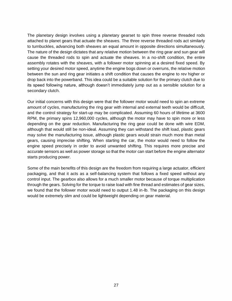
The planetary design involves using a planetary gearset to spin three reverse threaded rods
attached to planet gears that actuate the sheaves. The three reverse threaded rods act similarly
to turnbuckles, advancing both sheaves an equal amount in opposite directions simultaneously.
The nature of the design dictates that any relative motion between the ring gear and sun gear will
cause the threaded rods to spin and actuate the sheaves. In a no-shift condition, the entire
assembly rotates with the sheaves, with a follower motor spinning at a desired fixed speed. By
setting your desired motor speed, anytime the engine bogs down or overruns, the relative motion
between the sun and ring gear initiates a shift condition that causes the engine to rev higher or
drop back into the powerband. This idea could be a suitable solution for the primary clutch due to
its speed following nature, although doesn’t immediately jump out as a sensible solution for a
secondary clutch.
Our initial concerns with this design were that the follower motor would need to spin an extreme
amount of cycles, manufacturing the ring gear with internal and external teeth would be difficult,
and the control strategy for start-up may be complicated. Assuming 60 hours of lifetime at 3600
RPM, the primary spins 12,960,000 cycles, although the motor may have to spin more or less
depending on the gear reduction. Manufacturing the ring gear could be done with wire EDM,
although that would still be non-ideal. Assuming they can withstand the shift load, plastic gears
may solve the manufacturing issue, although plastic gears would strain much more than metal
gears, causing imprecise shifting. When starting the car, the motor would need to follow the
engine speed precisely in order to avoid unwanted shifting. This requires more precise and
accurate sensors as well as power storage so that the motor can start before the engine alternator
starts producing power.
Some of the main benefits of this design are the freedom from requiring a large actuator, efficient
packaging, and that it acts as a self-balancing system that follows a fixed speed without any
control input. The gearbox also allows for a much smaller motor because of torque multiplication
through the gears. Solving for the torque to raise load with fine thread and estimates of gear sizes,
we found that the follower motor would need to output 1.48 in-lb. The packaging on this design
would be extremely slim and could be lightweight depending on gear material.

28
4.4.4 Lead Screw Actuation Method
Figure 9. Lead screw actuation concept.
The lead screw method involves a lead screw that is concentric with the CVT pulley, with the lead
nut fixed to one of the sheaves with a bearing. The other face is fixed axially, and thus the bearing
allows the second face to spin without the lead screw spinning. Turning the leadscrew moves the
lead nut in and out which moves the moveable sheave. The main benefit of using this system was
the compatibility and packaging, at least for the outboard moving sheave face. Unfortunately,
there would be foreseeable packaging problems with concerning the inward moving sheave face
as there is limited space available. The lead screw design includes low rotating mass, although
not as low as the arm actuation methods.
4.5 Selection Process
Having fielded these four ideas, we gave careful consideration to which attributes were most
important to our success. We then assigned weights to each attribute and compared all concepts.
The process is summarized in Appendix 11.2.
Each design had its own pros and cons. The planetary design was a strong contender due to very
rapid shift response, compact and simple packaging, and minimal overall weight. However,
several components, such as the ring gears, may require expensive custom manufacturing. The
central lead screw concept promised fast and precise shifting control, along with a high reliability
due to the direct nature of control. However, even if tolerance stack-up could be avoided on the

29
multiple interfacing surfaces, the central lead screw design would be extremely difficult and time
consuming, or expensive, to machine.
Ultimately, the chosen design via decision matrix was the pivoting lever arm concept. However,
each design was complex, and at this stage each had many purely theoretical variables.
Therefore, the decision matrix was largely conceptual and was based on few quantified metrics
or analysis results. To more thoroughly vet our selection process, a concerted effort was made to
analyze each of the three leading concepts from a first-principle, engineering analysis approach.
To this end, 3D CAD models were developed to provide preliminary dimensions and other
properties for comparison. Examples of these models are available in Appendix 11.5.
From the developed models, we investigated shifting reaction times, inertial effects on acceleration, and overall mass. The rotational inertia of the Gaged CVT was measured against the rotational inertia of the newly designed eCVT. When compared, the rotational inertia of the Gaged CVT was measured at 54.2 lb in2 while the rotational inertia of the designed eCVT was almost a fourth of that, measuring in at 15.1 lb in2. With such a decrease in rotational inertia, the response time of the newly designed eCVT was greatly increased allowing for better system performance.
Regarding shifting reaction times, each method ultimately used a similar threaded rod to either
directly or indirectly move the sheaves relative to each other. Any difference in shift speed
resulting from differences in configuration would be easily accommodated by commonly available
motors under consideration by the controls team.
However, the development of CAD models amplified and clarified the manufacturing issues
identified early on. The success of the planetary gear design depended on a careful development
of custom gears, which would have to be precisely located on the side of the sheaves, both
concentrically with the CVT shafts and relationally with the other gears in the planetary set. The
central lead screw design presented similar challenges, with a large number of high-precision
coaxially located machined surfaces, each of which would require precise tolerancing to interface
with all the others. The primary difficulty with both options was our inability to manufacture these
components in-house. This would prevent us from achieving the 90% in-house specification, and
likely our budget constraints. Furthermore, the modeling solidified the lead screw concept’s
packaging issues. Despite exploring multiple possible configurations, each yielded an assembly
that, when coupled with the actuating motor and casing, would protrude past the frame of the car.
Also, concerns were raised due to the inherent nested component layout, which would complicate
maintenance and repairs.
Having performed due diligence in exploring all alternatives, we confirmed our selection of the
pivoting arms design. Despite presenting risks, such as the possibility of deflection disrupting
precision shifting, our motivation was our ability to manufacture most, if not all components in
house. While the pivoting lever arm design may add a bit more weight to the entire system, all of
it is off of the shaft, allowing for almost no rotating mass. Service and reliability are additional
areas where the pivoting linkage arm design excels. Having the ability to remove the entire CVT
at once greatly improves the opportunity for easier tuning and maintenance. It also has a small

30
number of simple components to make, which will allow for early prototyping and fitting to the car.
This can help controls team tune their system to the CVT early on and may allow for multiple
iterations of the system. When compared to the rest of the other systems researched and
analyzed, it is believed that the pivoting lever arm concept will offer the best chance of success.
Late in the final design stage, it was determined that the pivoting arm design contained a number
of redundant components. The first iteration was designed for two arm assemblies sliding both
sheaves on each assembly. However, the same objective could be achieved with only one sheave
sliding. This enabled design simplification, reduction in weight, increased efficiency due to fewer
bearings, and increased reliability. These changes did not compromise any of the original
objectives such as accessibility, tunability, etc. There were only two drawbacks to this change.
First, forces were redirected into the backing plate, which were previously self-cancelling within
the arm mounting brackets and leadscrew. Second, a slight belt misalignment issue was created
due to the belt traveling up or down the primary and secondary at different rates. This is despite
mitigating most misalignment via actuating opposite sheaves.

31
5. Final Design
5.1 Final System Design
Figure 10. Final system design.

32
Figure 10 illustrates the design we proceeded with through CDR. After presenting this design, we
came to realize that there were many problems we still faced and were forced to redesign many
components. Our final design will no longer fit the 2018 vehicle and will only be able to be tested
on the 2019 vehicle for reasons explained in the bearings section. This entire chapter will dive
deeply into the detailed design of each component and the analysis behind it. We will specifically
note changes that occurred after CDR wherever they appear. Our final design has both primary
and secondary pulleys actuated through a set of lever arms with an ACME lead screw on the end.
Each pulley has one of the two faces actuated, and the other is fixed axially. The final achievable
ratio range has a speed ratio of 0.71:1, and a torque ratio of 3.94:1. The overall system is
estimated to weigh just under 16 lbs.
5.1.1 Ratio and Geometric Considerations
In order to meet our engineering specifications, we had to maintain a ratio range of roughly 4:1 to
0.75:1. All considerations for meeting this specification were purely geometry and packaging
related. The CVT ratio is calculated by the ratio of the belt’s pitch diameter on the secondary
pulley to the belt’s pitch diameter on the primary pulley. It is important to note that this is the pitch
diameter and not the outer diameter of the belt. The pitch diameter occurs at the chords inside
the belt because the power is transmitted through the tension in these chords. Figure 11 below
shows a picture of a Gates belt’s construction illustrating where the chords are. The exact position
of the chords depends on the design of the belt and will change with different models of belts. It
is necessary to reference the manufacturer’s specifications to get outer lengths and pitch lengths
of belts.
Figure 11. Belt Construction.
At a very basic level, the amount of linear sheave travel needed to achieve a certain ratio is
determined by the sheave angle. If a sheave has a larger angle, more linear travel is needed for
a given increase in belt diameter. This idea is shown in the geometry of the figure below.

33
Figure 12. Sheave geometry.
Where: (x, y):
(x’, y’): (Δx, Δy):
Belt’s original position Belt’s new position Change in belt’s position
Another important consideration in the CVT ratio is the fact the belt is a fixed length. It seems
obvious when stated like this; however, this statement carries important implications. It means
that for a given belt diameter on one pulley there is only one diameter that the belt can have on
the other pulley if the belt is to remain taut. This can be illustrated by the equation for belt length
below.
L =2C + 2(D+d) + (D-d)24C
L: C: D:
Belt pitch length Center to center distance of the pulleys Pitch diameter of secondary pulley

34
d: Pitch diameter of primary pulley
When holding the belt pitch length constant and choosing a pitch diameter of the primary pulley,
it can be seen that the pitch diameter of the secondary pulley can be calculated. Putting all of
these concepts together, it is possible to develop a curve of linear sheave travel versus CVT Ratio
for both the primary and secondary pulley. The curve is shown in the figure below.
Figure 13. CVT ratio versus shifting travel.
This graph shows that for a given CVT ratio there is only one distinct linear position of the primary
and one distinct linear position of the secondary. It is also notable that the graph is not linear. This
happens because a given change in CVT ratio does not equate to a constant change in belt length
being wrapped around the pulleys. The amount of belt length being wrapped around the pulleys
changes depending on the ratio, which causes non-linear curves for both the primary and
secondary travel. From this spreadsheet we were also able to calculate the maximum and
minimum primary and secondary diameters. It is important to note that these diameters are pitch
diameters which means that the belt length input into this spreadsheet must be the pitch length.
However, this spreadsheet does not take into account the physical geometry of the sheave, and
therefore cannot be the sole consideration for the ratio range. We needed to also account for the
dimensions of the belt and the physical limitations of the sheaves. This means that we needed to
check whether the pulleys could physically clamp on the belt throughout all shifting travel. Using

35
a CAD sketching tools we were able to quickly check the geometry of the sheaves. A picture of
this sketch is shown below.
Figure 14. Sheave geometry SolidWorks sketch.
While holding the angle of the sheaves constant, we changed the belt diameter dimension to
simulate a change in ratio. This showed us how close the center of each sheave was at different
diameters (the driven dimension). We had to make sure that the belt was able to reach the
minimum and maximum radii calculated from the excel spreadsheets. The limit on the maximum
torque ratio was the minimum diameter on the primary since the belt had to wrap around the shaft,
which was already 1.4” in diameter and since the secondary sheave could not get bigger than 9”
due to packaging concerns. In addition, we had to make the primary sheave slightly larger in
diameter than the Gaged primary in order to reach a maximum speed ratio of ~0.75:1. An
interesting note that we found out from this type of analysis is that the Gaged CVT is limited by
its sheave geometry and belt width to a maximum speed ratio of roughly 1:1. This is the reason
why we have never measured a ratio on the Gaged CVT with a lower maximum speed ratio.
In addition to checking that the belts would be able to operate at the diameters that we need, we
also had to account for the primary being able to clutch in and out. We added an extra 0.25” of

36
travel to the amount needed for the maximum belt width to allow for clutching. This means that
for belts with a width less than this, there will be even more travel for clutching.
The final consideration for the travel was the physical packaging in the car. This was especially a
problem for the secondary because the inboard sheave is the one that moves on the secondary.
We checked the packaging from a moving SolidWorks model to ensure that nothing clashed.
5.1.2 Sheaves and Belt
The interface between the sheaves and belts is of vital importance because it is how the torque
and power of the engine is transmitted to the wheels. The design decisions of both the sheaves
and belt were intertwined with each other, so it only makes sense to address both of them at the
same time. The driving factors in the design were ratio range and packaging (addressed earlier),
ease of sourcing, and efficiency.
Table 7 outlines all of our design decisions for the belt and sheaves. It is important to note that
we specified a belt for both the 2018 car and the 2019 car, but this was before we realized our
design only works on the 2019 car. This has to do with the loading of the bearings on the input
shaft, and it is discussed in Section 5.1.9 about bearings.

37
Table 7. Belt and sheave design decisions.
Specification 2018 Car (10” nominal center to
center)
2019 Car (8.5” nominal center to
center)
Belt Part Number Gates, 33G3836 G Force Gates, 30G3596 G Force
Belt Angle (deg) 26 26
Belt Outer Length (in) 39.5 37.125
Belt Pitch Length (in) 38.36 35.96
Belt Top Width (in) 1.344 1.313
Belt Thickness (in) 0.567 0.537
Theoretical Center to Center (in) 10.1 8.9
Max Torque CVT Ratio 3.85:1 3.94:1
Max Speed CVT Ratio 0.69:1 0.71:1
Fixed sheave to fixed sheave offset - inboard to inboard (in)
0.556 0.556
CVT Ratio at belt centerline crossover 2.18:1 2.38:1
Primary
Physical Diameter (in) 7.25 7.25
Minimum Pitch Diameter (in) 2.25 2.19
Maximum Pitch Diameter (in) 6.798 6.738
Linear Shifting Travel (in) 1.05 1.05
Minimum Sheave Separation (in) 0.032 0.015
Maximum Sheave Separation (in) 1.082 1.065
Max Sheave Separation - accounting for clutching distance (in)
1.25 1.25
Secondary
Physical Diameter (in) 8.95 8.95
Minimum Pitch Diameter (in) 4.693 4.752
Maximum Pitch Diameter (in) 8.663 8.629
Linear Shifting Travel (in) 0.917 0.895
Minimum Sheave Separation (in) 0.156 0.133
Maximum Sheave Separation (in) 1.072 1.028

38
Ease of Sourcing
We wanted to choose a belt that was readily available due to our historical problems with ordering
belts on the Baja team through Gaged. We decided to choose a Gates belt because of their wide
selection and their willingness to share information to help us with our design. Gates has three
different options for their variable speed V-belts: G-Force, Powerlink, and Multispeed. The G-
Force is a belt made for CVTs in a racing scenario. Powerlink belts are made for lower
displacement engines than ours. Multispeed belts are made to be OEM replacements and not
used for automotive applications. For these reasons, we chose to use a G-Force belt.
One of the practical reasons justifying a choice of 13-degree sheaves (26 degree included angle)
is that Gates has a large selection of 26-degree belts. In addition, the Gates G-Force belts are
sold at many local distributors including O’Reilly Auto Parts. For these practical reasons as well
as ratio range justifications the 26-degree G-Force belt with a sheave angle of 13 degrees was
chosen
Efficiency
The first step we took in attempting to tackle efficiency was trying to understand the relationship
between belt angle and sheave angle. An employee of Gates recommended that the belt angle
be the same as the sheave angle. However, we thought about the relationship between belt and
sheave angle a little closer after reading page 14 of Aaen’s Clutch Tuning Handbook. Aaen talks
about the development of knowledge on efficiency of snowmobile CTVs. He says that most
modern CVTs have a smaller primary angle than the secondary. This has to do with the fact that
the belts angle gets smaller when wrapped around the sheave at a tight radius. To account for
this, primaries tend to have a smaller angle in order to better match the belt angle at a tight radius
and better support the belt during hard accelerations. We confirmed this belt behavior with our
own measurements. When we bent the belt the opposite way that it normally bends, we saw that
the angle increased significantly. We measured an angle of 18 degrees when bent backwards
and an I’ll angle of roughly 12.5 degrees when simply set it on a table without significant bends.
Even with this discussion in the Clutch Tuning Handbook, we decided to match the belt angle to
the sheave angle because we were less concerned about hard accelerations than we were about
regular operations where the angle change of the belt is minimal.
Another consideration to take into account for efficiency is belt misalignment between the primary
and secondary sheave. This is shown in Figure 15.

39
Figure 15. Belt misalignment.
The belt should be as straight as possible between the two pulleys for the highest efficiency.
Gates has a document on their website that recommends a maximum misalignment of ⅓ of a
degree for V-belts in automotive scenarios.
Minimizing belt misalignment is the reason why the outboard sheave moves on the primary and
the inboard sheave moves on the secondary. If it weren’t this way, the belt would become severely
misaligned through travel. However due to the fact that the primary and secondary have different
amounts of linear movement through travel means the belt will still be somewhat misaligned
through travel. Let’s go back to the graph of CVT ratio versus linear travel:

40
Figure 16. CVT ratio versus shifting travel.
This graph assumes that the belt is perfectly aligned between the primary and secondary at the
maximum torque ratio of ~4:1. This is the starting position for the system which means that neither
the primary nor the secondary have linearly shifted yet. On this graph, the belt misalignment is
the difference along the x-axis of the primary and secondary travel. In this configuration, the
maximum misalignment is 0.15”. Over the 8.5” center to center distance this would cause a
misalignment of over 1 degree. This is unacceptable because of a Gates recommendation that
automotive belts should not have more misalignment than 0.3 degrees. It is impossible always
have the primary and secondary perfectly aligned at all times because they move different linear
distances over their shifting travel. However, it is possible to reduce the misalignment as much
as possible. For this reason, it is necessary to offset the primary from the secondary and have
the point of perfect alignment be somewhere in the middle of travel. Figure 17 shows the resultant
belt misalignment with the correct offset from primary to secondary.

41
Figure 17. Belt misalignment graph.
The actual magnitude of the belt centerline distance is less important than the difference between
the primary and secondary belt centerline distance. This is because the difference between them
is the misalignment. In the graph, there is a place where the two curves intersect. This is the point
where the belt is perfectly aligned between the primary and the secondary; this is what we called
the crossover point. By setting a different offset between the primary and secondary, we were
able to pick the location in the travel of the crossover point. We decided to put the crossover point
in the middle of the travel because that is where the CVT usually operates. The offset of these
sheaves is set by the length of the spacers the primary and secondary pulleys are mounted to.
After we determined what offset we wanted, we were able to specify the length of these spacers
in Solidworks. In order to fix the offset, we measured from a fixed point on the primary to an
arbitrary point in space and did the same for the secondary. The difference between the two
measurements is the offsets. It is critical to measure to a stationary point on the pulleys. In Figure
15 above, the dimension “A” is an incorrect way to measure the offset because it measures to the
moving sheave on the secondary. This dimension will change through shifting, where the offset
dimension should never change.

42
The final consideration for efficiency had to do with coatings on the sheave and the belt. Gates
recommended against using any coatings for either the sheaves or the belt. After doing some
research online, we found a BYU master’s thesis talking about coatings on CVT faces. This thesis
concluded that it was beneficial to have a coating on the face for wear. However, we have decided
not to pursue any coatings per the Gates recommendation. If we start to have a wear problem we
will look further into protective coatings, but at this juncture we are not exploring coatings any
further.
Detailed Sheave Design
The sheaves are all made of 6061 aluminum. The diameter of the primary sheaves is 7.5” and
the secondary sheaves have a diameter of 8.95”. The angle on both of them is 13 degrees in
order to match the belt which has a total angle of 26 degrees.
Unfortunately, each of the four sheaves are a unique part. This made manufacturing a little bit
harder, but it was necessary because of the different diameters of sheaves and the different
connections that each sheave needed. As stated before, the angle of the sheaves was determined
to match the angle of the belt. There were some packaging concerns about the linear sheave
travel. The larger the sheave angle, the more sliding travel distance over the shafts would be
needed for the belt to traverse the full sheave face. In order to limit the dimensions of the overall
package, i.e. shaft lengths, we chose a 13-degree sheave angle instead of a 15-degree angle.
Originally the sheaves were made very thin with ribs on the back of them for stiffness. This idea
was eventually scrapped because of the uncertainty in the stress and deflection that the sheaves
would experience.
The fixed sheaves are connected to the shafts by two 1/8” pins. These pins transfer the torque
from the fixed sheave, and the drive bushing transfers the torque from the sliding sheave. The
sheaves are clamped against the shaft by the bolt that runs through the center of the shaft and
clamps the entire assembly together.
Additionally, there is a reluctor wheel superglued to the back of the primary sheave. This is a
ferrous part with holes located radially around it. It rotates with the primary sheave so that a hall-
effect sensor can sense the speed the engine is spinning.
5.1.3 Shafts
The primary concern when designing the shafts was that they must transmit torque through both
sheaves as well as provide a sliding or rolling surface so that at least one sheave on each pulley
may move axially to change ratio. In other words, we have to create a system that allows for
controlled linear and rotary motion simultaneously. The minimum size of the shaft was constrained
by the diameters of the engine shaft and gearbox input shaft for the 2019 vehicle. In the future,
the gearbox input shaft can be sized down which would allow for a smaller secondary shaft. The

43
maximum size was constrained by ratio range requirements. This left us a very narrow window to
design within, although it was soon clear these shafts will be quite large for the application and
will have infinite life.
Sliding Shaft Profile
First of our considerations was the square shaft which is found on the Gaged GX9 primary. To
offer context, the Gaged GX9 CVT uses a square primary shaft with a brass drive bushing to
transmit torque through the actuated sheave while sliding. First, torque flows from the engine
shaft into the primary shaft. Torque then flows from the shaft and into the fixed sheave through
threads and into the sliding sheaves through a drive bushing. This shaft can be seen in figure 16
and the associated drive bushing can be seen in Figure 16.
(a) (b)
Figure 18. (a) Gaged Engineering primary shaft. (b) Gaged Engineering primary drive bushing.
As seen in the figure, the Gaged Engineering primary shaft has a circular section with an internal
keyway that mates with the engine shaft of the Briggs & Stratton Model 19 engine. The non-
actuated sheave is retained and transmits torque through the threads at the end of the shaft. The
square portion of the shaft is used as a bearing surface, allowing the actuated sheave to slide
axially along the shaft. The Gaged Engineering secondary uses a very different method to
transmit torque while actuating. Torque flows into the secondary from the sheaves through the
belt. Unlike the primary, the secondary actuated sheave transmits torque through the helix and
pins into the fixed sheave.

44
Figure 19. Gaged Engineering secondary shaft.
Friction between the drive bushing and shaft was our main concern with the method used in the
GX9 primary. As the primary is loaded, the bushing twists relative to the shaft and incurs
significant friction opposing the shift. In order to quantify this friction, we performed a very
rudimentary test that simulated the load seen during driving and measured force required to shift
to get a ballpark number for friction. We knew the amount of torque we were transmitting, so we
assumed everything to be static and hung weights with a lever arm and measured a shift force of
110 pounds from a fish scale. We realize our static assumption is poor, although this gave us a
starting place. Next, we briefly considered sliding splines. Sliding splines are commonly found
before a driveshaft meets a differential on production vehicles. Splines offer a compact way of
transmitting a significant amount of torque, although we currently have no time efficient way to
measure friction associated with sliding splines, and therefore had to move on. Finally, we
considered a ball spline system similar to the one used on Bert Transmissions pictured in Figure
20. Ball splines are essentially linear ball bearings that can transmit torque with very little friction.
Figure 20. Ball spline concept.

45
Ball spline systems are able to be purchased on McMaster-Carr relatively cheaply and are rated
for torque figures well above the output of the Briggs & Stratton Model 19. Models similar to the
one shown in Figure 21 can be purchased at different sizes and rated torques. After some
investigation into off the shelf ball splines, we soon found that the part numbers to transmit the
necessary torque were much larger than practical and would reduce our ratio range.
Figure 21. Sample ball spline available at McMaster.
We considered making our own ball spline cut into our sheaves and shafts, however this was
quickly rejected due to the risk associated with manufacturing races into an aluminum sheave.
Although this option shows the most promise for the future, especially with the Baja team making
their own CV cups for the 2019 season. We could not justify manufacturing a performance critical
feature that nobody had any experience with. It would put our overall design reliability at risk.
All considered, we decided to move forward with a square shaft similar to the Gaged Engineering
primary shaft. We realize this is a large compromise, but we made this choice because we have
the best understanding of the frictional forces associated with it. Small changes were made in
both shafts due to manufacturing issues that will be covered in the manufacturing chapter.

46
Figure 22. Final shaft design.
5.1.4 Lead Screw
The lead screws translate torque from the actuating motor/gearbox shaft into translational force
required to move the sheaves along their respective shafts. Our initial approach was to seek the
lowest friction design possible, which is a ball bearing type design. Also, at the beginning stages
of design, we specified a lead screw with both left and right threads, meeting in the middle. This
would allow a single motor to actuate the original double-sliding sheave design. However, this
design would require a custom order from a lead screw manufacturer. Unfortunately, Nook
Industries quoted our request at $3,308. At over twice our entire project budget, this approach
was abandoned. Instead, we sought to use an “off the shelf” Acme screw design. This choice was
simplified when the CVT design was reduced to single sheave actuation. By eliminating the need
for opposing threads, many more options became available with greatly reduced lead times. The
obvious drawback to this approach was that a standard screw thread would have inherently more
friction than a ball-screw design. However, ball-screws also require lubrication. A lubrication
system would have created enormous complexity and added weight, since no lubrication could
be allowed to contact the sheaves or belt. Thus, the additional friction of a standard Acme
threaded lead screw and nut was a necessary compromise.
The chosen lead screw is ¾” major diameter made of 304 stainless steel. It is case-hardened and
has a low friction coating that increased the efficiency to 50%. We worked closely with a company
called Helix Linear who eventually sold us the lead screws. Given our loads and speeds, Helix
gave us specifications for our lead screw which are shown in Figure 23 below. The part number
of the screw is 075166RS/00/00/8.00/S and the part number for the nut is NFA075166R.

47
Figure 23. Lead screw specifications
The lead screw connection to the motor shaft was a very tricky design problem. Because of
packaging concerns, we could not connect the two shafts with a standard coupler. Instead, we
came up with a custom design that connects the lead screw to the motor D-shaft via a set screw.
The figure below shows the design.
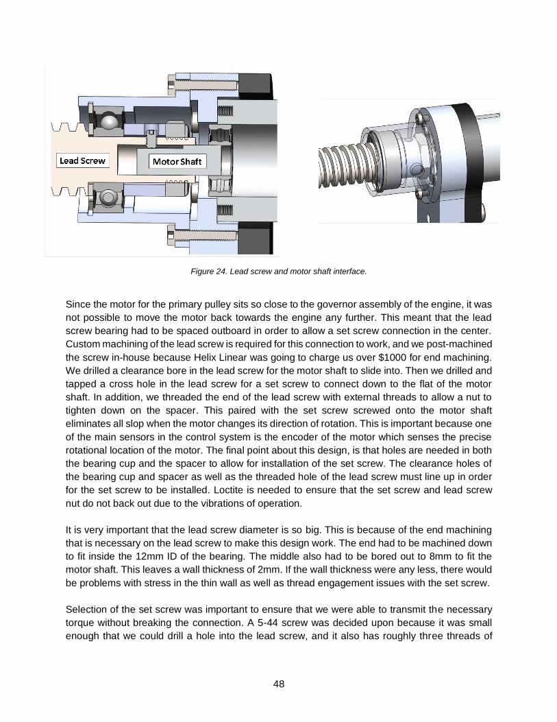
48
Figure 24. Lead screw and motor shaft interface.
Since the motor for the primary pulley sits so close to the governor assembly of the engine, it was
not possible to move the motor back towards the engine any further. This meant that the lead
screw bearing had to be spaced outboard in order to allow a set screw connection in the center.
Custom machining of the lead screw is required for this connection to work, and we post-machined
the screw in-house because Helix Linear was going to charge us over $1000 for end machining.
We drilled a clearance bore in the lead screw for the motor shaft to slide into. Then we drilled and
tapped a cross hole in the lead screw for a set screw to connect down to the flat of the motor
shaft. In addition, we threaded the end of the lead screw with external threads to allow a nut to
tighten down on the spacer. This paired with the set screw screwed onto the motor shaft
eliminates all slop when the motor changes its direction of rotation. This is important because one
of the main sensors in the control system is the encoder of the motor which senses the precise
rotational location of the motor. The final point about this design, is that holes are needed in both
the bearing cup and the spacer to allow for installation of the set screw. The clearance holes of
the bearing cup and spacer as well as the threaded hole of the lead screw must line up in order
for the set screw to be installed. Loctite is needed to ensure that the set screw and lead screw
nut do not back out due to the vibrations of operation.
It is very important that the lead screw diameter is so big. This is because of the end machining
that is necessary on the lead screw to make this design work. The end had to be machined down
to fit inside the 12mm ID of the bearing. The middle also had to be bored out to 8mm to fit the
motor shaft. This leaves a wall thickness of 2mm. If the wall thickness were any less, there would
be problems with stress in the thin wall as well as thread engagement issues with the set screw.
Selection of the set screw was important to ensure that we were able to transmit the necessary
torque without breaking the connection. A 5-44 screw was decided upon because it was small
enough that we could drill a hole into the lead screw, and it also has roughly three threads of

49
engagement in the wall thickness of the lead screw. The Figure 25 shows the chart used to
determine set screw sizing.
Figure 25. Set screw sizing chart.
We did the calculation of holding torque necessary by assuming a fully circular motor shaft. The
shaft is actually a D-shaft, and our set screw would sit on the flat of the D. Assuming a circular
instead of D-shaft is a conservative assumption because the flat will only help to transmit the
torque better than a regular circular shaft. Taking into account the 28:1 gearbox, the maximum
torque that would be output to the lead screw is 16.4 in-lb. This means the #5 screw has a factor
of safety of roughly 1.9. The true number of this factor of safety is likely higher due to the D-shaft.
We found a source that says the set screw connection to a D-shaft improves the torque carrying
capacity by roughly 6%.
The final design of the lead screw includes a mechanical stop that is screwed into the lead screw.
This stops the motion on the sheaves so that they can only linearly travel as far as they need to
in order to meet the necessary ratio range; they cannot travel farther than this. This is because
the motors need to be zeroed upon startup. The easiest way to do this is to stall the motor and
call that location “zero.”
5.1.5 Arms
The arms act as a lever between the lead screw and sheaves, boasting a 2.5:1 leverage ratio and
2.03:1 lever ratio on the primary and secondary pulleys, respectively. Stiffness is a crucial factor
of the linkage arms; if the arms were to deflect extensively, the overall performance of the system
would suffer. Deflection in the arms would affect the ratio range and add ambiguity to the system
when tuning. With this in mind, hand calculations show that the arms will only deflect 0.0075” with

50
the designed 400 lb actuation force acting on each arm. This deflection is acceptable, as it will
only affect the CVT ratio by about 0.1. In theory, the controls should compensate for any
deflection, but we wanted to play it safe. The profile of the arms and the location of the slots was
designed to allow at least 0.100” of clearance through the shift. Originally, 7075 aluminum or
similar high-grade material was specified for maximum strength. However, the high material cost
was not justified given that we were stiffness driven and did not need the marginal increase in
strength. Instead, 6061-T6 was sourced.
At CDR, we presented a design that used pins and r-clips to retain the roller bearings and arms.
We decided that this was insufficient given the amount of unknown flex in the system, so we
decided to use cap screws to retain the roller bearings, and we added a sheet metal brace to
keep the two arms from splaying out and to keep the system more rigid.
Figure 26. New bolted connections and brace.
Slots have been designed at the locations where roller bearings from the shift fork and lead screw
carrier are in contact with the arm, to account for vertical translation and avoid an overly
constrained system. Originally, a press-in steel insert was planned to provide a hardened surface
for the roller bearings to contact. These inserts would be constructed from sheared sheet metal

51
and secured in the slots with epoxy. Grainger 4XEX6 16mm Track Rollers were initially selected
for the application due to their availability and decreased friction over bushing bearings. We
anticipated that the pressed in steel inserts would wear down and need to be replaced after a
typical life cycle has passed, such as one race season. However, when placing the order for the
selected track rollers, the price was far higher than anticipated. At $45 each, a single car-set
would cost $360 plus shipping and tax before considering spare parts. In contrast, by revising our
design to use a much more commonly available 19.05mm (¾”) size roller, cost was reduced to
$110 for a single car-set. The larger size roller required eliminating the steel slot liners. This
decision increased risk of the aluminum arms wearing down quickly from the action of the steel
rollers. However, we decided this risk was acceptable in order to achieve our target price. Testing
and observation over the first race season will confirm how quickly the bare aluminum slots wear
with actual use.
5.1.6 Case
The case has undergone several radical re-designs to match developments in the overall eCVT
design. Originally, when the eCVT was designed with both sheaves actuated, a simple sheet
metal design was developed. The basic goals were to comply with SAE safety rules, minimize
package size, maximize ease of maintenance access, maximize ease of manufacturing, and
provide protection from water and dust intrusion. The SAE rules require any component spinning
faster than the vehicle’s wheels be contained radially with at least ⅛” aluminum.
Based on previous Baja team experience, the labyrinth seal design in current use was rejected
due to difficulty of manufacture. Instead, automotive door seals would be used around the
perimeter of the side banding material and be pressed into the opposing surface of the back cover
by rubber bands or latches. A planar sheet metal back cover was modeled with a carefully
developed outer profile. This profile allowed as much internal clearance as possible for ease of
access to the CVT components, while not creating interference issues on any other component
on the current 2018 vehicle. One desirable feature of the existing CVT case was the one-piece
front cover and perimeter band. This design allowed maximum access to the CVT for
maintenance when the cover was removed. However, our new package size was much larger
than the case currently in use. This meant that we could no longer weld the outer covering band
to the front cover because we would not be able to extract such a large component from between
the eCVT and frame/suspension. We decided to use either a three-piece design consisting of
front cover, perimeter band and back cover, or to weld the perimeter band to the back cover and
create a two-piece design. Either design would be held together with rubber bands or latches.
Because the welding could be completed at any time, the final decision would be made after
finding the best fit with the eCVT installed in the car.
Shortly before CDR, the decision was made to actuate only one sheave on each pulley. While
this provided many benefits to the eCVT design, the belt clamping force was no longer resolved
within the arm mounts and lead screw. Instead, these forces would be transmitted to the back
cover. We therefore investigated changing the back cover into a heavier backing plate design.
Deflection of this backing plate was a major concern due to the direct effect on shifting accuracy.
Accurately modeling a plate in bending due to concentrated forces normal to the plate is an

52
advanced analysis problem that we are not equipped to perform. However, simplified modeling
was performed using a simply-supported beam in bending, with dimensions representing a strip
of the backing plate between the application points of the loads. This method is conservative since
the strip is isolated from the support received from the surrounding plate. This simplified modeling
revealed that a 1/8th inch 7075-T6 aluminum plate could deflect and alarming 1.5 inches.
Switching to steel 1/8th inch plate could reduce the deflection to around ½ inch. However, a steel
backing plate would add far too much weight for our specifications, and yet would still result in
unacceptable deflection. Similarly, increasing the aluminum plate thickness to 3/8ths of an inch
could reduce the deflection to just under 1/16th of an inch. However, the added mass would not
be justified since the resulting deflection is still unacceptable.
Our final design approach used a heavy, aluminum rib backed with composite material to resolve
the clamping forces. Details of the ribs are discussed in a later section. The inclusion of support
ribs allowed the case design to revert to the light-weight sheet metal design, which would not
need to support any significant loads. The final design is shown in Figure 27 below.
Figure 27. Final case design.
Another result of the decision to actuate one sheave per pulley was the offset mounting of the
primary assembly in relation to the secondary. This meant that a jog in the back cover was
required to accommodate the support ribs and still fit around the engine. The jog created a
challenge in aligning the mounting holes for the primary and secondary assemblies on the back
cover. We initially felt that if the jog was to be created by a press-brake, then extremely tight
bending tolerances would be required to keep both hole patterns spaced relative to each other.
We therefore designed a three-piece back cover consisting of the jog section along with primary
and secondary sections. These pieces could be laser or water-jet cut to guarantee each hole
pattern was accurate and included tab-and-slot alignments to guarantee in-plane feature
alignment. The only remaining challenge would be welding the assemblies together square in the

53
correct planes to set the spacing between hole patterns. To assist with this challenge, gusset
pieces were modeled that also featured tab-and-slot alignment.
However, an opportunity arose to have the case CNC formed at Borden Precision, a local sheet
metal shop. With the assurance of holding tighter tolerances, we abandoned the multi-piece
design and modeled a single piece jogged back cover. Also, we determined that generous
tolerances could be given to the mounting holes since they were in actuality merely pass-through
points for the standoff mounts of the eCVT. Any resulting extra space around the standoffs could
be sealed with RTV or similar.
The front cover was changed from a flat, planar design and instead incorporated a single bend
running diagonally across the case. This bend was required to prevent the lower back corner of
the case, in front of the secondary assembly, from protruding outside of the chassis tubing. Any
protrusion of the case outside of the protection of frame members would create an area extremely
vulnerable to damage during the common occurrence of vehicle-to-vehicle contact in a race.
Changes were also made to all three parts of the cover to specifically fit the 2019 vehicle, while
accommodating the latest iterations in the eCVT configuration.
Low-grade, ⅛” aluminum plate was specified for the band of sidewall material in order to meet
the safety requirements from the SAE race rules with minimum possible weight and cost. The
backing plate and front cover were specified as the same material in order to minimize cutting
time, brake-press setup time and material costs to the sheet metal shop.
Cooling considerations were considered early in the case design. One option considered was
mounting fans directly in the front and/or back covers, protected from water and dust by foam.
Also considered was attaching ducting to the covers as the current case design. The ducting could
be used with or without remotely located fans. We determined that any of these approaches could
easily be added to the case after all other manufacturing steps. Though heat has been a
suspected problem with the existing Gaged CVT and case, we do not have any conclusive data
to justify the added complexity, weight and electrical inefficiency of such cooling approaches.
Based on conversations with the controls team, we plan to embed thermocouples or other
temperature sensors in the case and monitor temperatures early in the testing process.
The current case design is unverified and incomplete for reasons outlined in the Manufacturing
and Project Management sections of this report.
5.1.7 Stiffener Ribs
The stiffener ribs, or just “ribs”, are the structural parts that the entire system mounts to. They
absorb all the resultant forces associated with the lead screw actuation.

54
Figure 28. Final design concept with mounting ribs shown in assembly view.
These parts were not in the original design for CDR. Before the ribs, the backing plate of the CVT
was going to be the structural mounting. This is shown below in Figure 29.
Figure 29. Old backing plate mounting concept shown in assembly view.
While this might seem simpler on the surface, there are three main problems associated with it:
difficult manufacturing, issues with deflection, difficult assembly.

55
The manufacturing is a problem because it is a sheet metal part that would have to have holes
be in exactly the right place even with two bends in the middle. There are a few potential solutions
to this such as making the backing plate in a few different pieces, but there are still a lot of
tolerance issues that could arise. This is one of the reasons we opted for the rib design.
Additionally, finding the deflection of the structural backing plate was a challenge. Being a plate
that is constrained at positions with bolts, it couldn’t be modeled as a typical beam. A finite element
analysis would be necessary to determine the stress and deflection due to the lead screw
actuation. Our team determined this to be too complicated, and we thought it would give us
inconclusive results. Instead we chose to go with the rib which was easier to analyze. Finally, the
ribs made our design much more modular between the primary pulley and the secondary pulley.
Everything could bolt on to the ribs, and the ribs could be bolted on individually. This was not the
case with the structural backing plate, and it was another factor that informed our decision to use
the ribs as structural mounting pieces.
Our main concern during the detailed design of the ribs was the deflection. Since they bolt to
either the engine or the gearbox in the center of the rib, the deflection of concern is at the upper
and lower ends of the ribs.
Figure 30. Primary and secondary ribs.
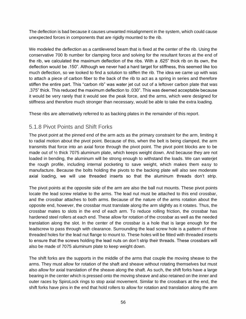
56
The deflection is bad because it causes unwanted misalignment in the system, which could cause
unexpected forces in components that are rigidly mounted to the rib.
We modeled the deflection as a cantilevered beam that is fixed at the center of the rib. Using the
conservative 700 lb number for clamping force and solving for the resultant forces at the end of
the rib, we calculated the maximum deflection of the ribs. With a .625” thick rib on its own, the
deflection would be .150”. Although we never had a hard target for stiffness, this seemed like too
much deflection, so we looked to find a solution to stiffen the rib. The idea we came up with was
to attach a piece of carbon fiber to the back of the rib to act as a spring in series and therefore
stiffen the entire part. This “carbon rib” was water jet cut out of a leftover carbon plate that was
.375” thick. This reduced the maximum deflection to .030”. This was deemed acceptable because
it would be very rarely that it would see the peak force, and the arms, which were designed for
stiffness and therefore much stronger than necessary, would be able to take the extra loading.
These ribs are alternatively referred to as backing plates in the remainder of this report.
5.1.8 Pivot Points and Shift Forks
The pivot point at the pinned end of the arm acts as the primary constraint for the arm, limiting it
to radial motion about the pivot point. Because of this, when the belt is being clamped, the arm
transmits that force into an axial force through the pivot point. The pivot point blocks are to be
made out of ½ thick 7075 aluminum plate, which keeps weight down. And because they are not
loaded in bending, the aluminum will be strong enough to withstand the loads. We can waterjet
the rough profile, including internal pocketing to save weight, which makes them easy to
manufacture. Because the bolts holding the pivots to the backing plate will also see moderate
axial loading, we will use threaded inserts so that the aluminum threads don’t strip.
The pivot points at the opposite side of the arm are also the ball nut mounts. These pivot points
locate the lead screw relative to the arms. The lead nut must be attached to this end crossbar,
and the crossbar attaches to both arms. Because of the nature of the arms rotation about the
opposite end, however, the crossbar must translate along the arm slightly as it rotates. Thus, the
crossbar mates to slots in the end of each arm. To reduce rolling friction, the crossbar has
hardened steel rollers at each end. These allow for rotation of the crossbar as well as the needed
translation along the slot. In the center of the crossbar is a hole that is large enough for the
leadscrew to pass through with clearance. Surrounding the lead screw hole is a pattern of three
threaded holes for the lead nut flange to mount to. These holes will be fitted with threaded inserts
to ensure that the screws holding the lead nuts on don’t strip their threads. These crossbars will
also be made of 7075 aluminum plate to keep weight down.
The shift forks are the supports in the middle of the arms that couple the moving sheave to the
arms. They must allow for rotation of the shaft and sheave without rotating themselves but must
also allow for axial translation of the sheave along the shaft. As such, the shift forks have a large
bearing in the center which is pressed onto the moving sheave and also retained on the inner and
outer races by SpiroLock rings to stop axial movement. Similar to the crossbars at the end, the
shift forks have pins in the end that hold rollers to allow for rotation and translation along the arm

57
as the arm itself rotates. The shift forks are 7075 aluminum to reduce weight over steel. This also
allows for a good bearing fit, as the bearing will easily press into the softer aluminum.
5.1.9 Bearings
Gearbox Bearings and Thrust Bearing
We overlooked the fact that our post-CDR secondary design was putting a thrust load into the
gearbox bearings and the engine shaft. To compensate for this, we worked with the Baja team to
change the input bearings to accept this new loading and place a thrust bearing on the primary
stiffener rib. However, the 2018 vehicle does not have the new gearbox bearings, which means
that the eCVT will only fit on the 2019 vehicle. The load is caused from the clamping on the belt.
As the belt is clamped, the reaction forces create a thrust load.
Shift Fork Bearings
The purpose of using a bearing on the shift fork is to isolate the spinning sheave from the
stationary arms. Immediately, we realized that the inner radius of this bearing must be quite large
due to the fact that it must mount onto the hub of the sheaves. The size of the mating surface on
the sheaves is dictated by engine or gearbox shaft size. Both shaft sizes are dictated for the 2018-
2019 season, so we were constrained to have a large sheave in order to fit around the shafts. We
therefore were exploring bearings with inner race bores between 40 and 50 millimeters. This
quickly eliminated many options and introduced large bearings that could interfere with tight
packaging and low weight. To compound the issue of a large inner race, the majority of the load
through the bearing is a result of the axial shifting force. Figure 31 shows a section view of the
primary assembly in order to visualize how clamping force travels through the bearing. As the
arms actuate to perform a shift, the entire clamping load goes through the bearing as a thrust
load.
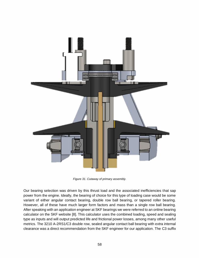
58
Figure 31. Cutaway of primary assembly.
Our bearing selection was driven by this thrust load and the associated inefficiencies that sap
power from the engine. Ideally, the bearing of choice for this type of loading case would be some
variant of either angular contact bearing, double row ball bearing, or tapered roller bearing.
However, all of these have much larger form factors and mass than a single row ball bearing.
After speaking with an application engineer at SKF bearings we were referred to an online bearing
calculator on the SKF website [8]. This calculator uses the combined loading, speed and sealing
type as inputs and will output predicted life and frictional power losses, among many other useful
metrics. The 3210 A-2RS1/C3 double row, sealed angular contact ball bearing with extra internal
clearance was a direct recommendation from the SKF engineer for our application. The C3 suffix

59
indicates extra internal clearance which will better handle axial loading, according to the
application engineer. In our scenario, this bearing has a frictional power loss of 110 W (0.15 HP),
a weight of 1.43 lb, and a very large form factor. For context, a single row ball bearing with the
same inner diameter had a power loss in the range of 200-240 W depending on the bearing and
was often less than half the weight with a much more convenient form factor. Due to the weight
and size of the 3210-A 2RS1, we investigated other options.
After some searching, we discovered the 6009-2Z/C3 from SKF, a deep groove single row
shielded ball bearing. The choice between rubber contact seals and contactless shields drastically
affect the efficiency of the bearing. Rubber seals often double the power loss for a given bearing.
Completely unshielded bearings were out of the question due to the generally dirty operating
environment. However, these bearings are inside a sealed case, so we anticipate that shields will
be sufficient to prevent incidental dust from destroying the bearing while driving. The 6009-2Z has
a power loss of 130 W (0.17 HP), a weight of 0.55 lb, and a much more convenient form factor of
half the width compared to the double row angular contact. In order to quantify whether or not this
lower weight was worth the increase in frictional power loss, we compared the power to weight
ratios of both cases. We assumed a range of weights near 350 lb for the car, plus the weight from
two of each bearing. The difference in power to weight ratio was at most a negligible 0.00002
Hp/lbf. We were therefore willing to accept the 6009-2Z based on packaging convenience.
The SKF 6009-2Z/C3 has a 45mm inner bore, 75mm outer diameter, and is 16mm wide.
Assuming a worst-case axial loading of 3.11kN, and radial loading of 0.4kN, operating
temperature of 75 ℃, and constant 3600 rpm, bearing life estimates were conducted using the
SKF calculator. However, because our loading was below a threshold for considering the effects
of varying load conditions, the SKF calculator did not incorporate any application factors for
consideration of high impact loading. The high factor of safety in this result tends to mitigate the
risk of using a shielded bearing versus contact seals. This bearing is commonly available from
internet retailers for less than $20.
Lead screw bearings
The purpose of placing bearings on the end of the lead screw is to transmit the load from the belt
clamping force into the backing plate. After we chose to actuate only one sheave per pulley, we
realized that the belt clamping forces no longer cancelled out within the lead screw. The Maxon
actuating motor is rated for 7N (1.5lbf) of axial force, so the 350lbs of clamping force needs to be
resolved through other means.
Lead screw bearing selection was primarily driven by geometric constraints. First, the minimum
dimensions of a machined surface on the end of the lead screw had to pair with the smallest
commonly available lead screw minor diameter that would provide the necessary shaft step to
transmit load to the inner race. Second, the smallest outer bearing diameter possible was desired
because the bearing housing would directly affect the case dimensions. Similarly, the bearing
width could require changes in packaging dimensions or other components to avoid restrictions
in useful travel of the lead nut.

60
These considerations lead to the selection of the SKF 6000-2RSH/C3 single row deep groove,
sealed ball bearing. This bearing has an inner bore of 10mm, an outer diameter of 26mm and a
width of 8mm. From the geometry of the arms, the worst-case belt clamping force translates to a
lead screw axial force of 280 lbf, with negligible radial forces expected. The SKF bearing life
calculations revealed that this force quite high for this diameter of bearing. Because of this, SKF
recommended an application factor of 0.13 on the L10 value, which results in 120 hours of life.
Though this number is far lower than the sheave bearings, it is still a factor of safety of 5 against
meeting our specifications. Frictional power loss calculations showed that the RSH sealed variant
would incur 5 watts of loss, versus 4 watts for the RSL shielded variant. This additional watt of
power per bearing would be supplied by the actuating motor and sourced from the alternator. The
alternator is presumed to supply excess power at a fixed mechanical drag, as long as the engine
is at optimal speed. Additionally, the lead screw bearing seal also seals the case against water
and dust intrusion where the motor shaft protrudes through the case. The RSH seal was
specifically designed to guard against pressurized water intrusion. Thus, the shielded variant was
specified to ensure maximum grease retention and cleanliness. This bearing is commonly
available for around $25.
Ball Transfer Rollers
The purpose of the ball transfer rollers is to counteract the frictional torque of the lead nut as the
CVT is shifting. This torque is a byproduct of the efficiency of the specified nut, so more torque is
induced for a lower efficiency nut. As the lead screw spins, there will be friction between the lead
screw and the plastic lead nut, causing the lead nut and attached lead nut carrier to spin. The
motion of the lead nut carrier traces an arc relative to the arm, so we needed something that could
roll in 2 principal directions simultaneously. Cylindrical rollers are only able to provide one
direction, so we decided to use ball transfer rollers. The lead nut carrier needs the ball transfer
rollers to further constrain the system. Figure 32 shows the location of the rollers and the moment
that they resist about the leadscrew.
Figure 32. Ball transfer rollers.
Ball Transfer Roller
Direction of Twisting
Moment due to Lead
Nut Friction

61
This frictional torque will also occur at the shift fork, although this time it is due to bearing drag.
The ends of the shift fork that contact the arms have a much larger area to slide on compared to
the lead nut carrier leading us to infer that the same solution used on the lead nut carrier is not
necessary at the shift fork. We added nylon washers between the shift fork and the arm to
minimize friction. This torqueing due to friction could be a much larger or smaller issue than
anticipated but will need to be confirmed with testing.
5.1.10 Lead Screw Bearing Housings
Development of the lead screw bearing housings was a matter of providing the support needed
to retain the bearing under the greatest axial load expected. The housings bolt to the backing
plate and incorporate mounting holes for the actuating motor/gearbox. 7075-T6 aluminum was
again chosen for low strength to weight ratio. FEA was performed to verify the critical dimensions
at the bearing seats. The design is complicated by the connection to the motor. Since the motor
shaft is connected to the lead screw with a set screw, there needed to be a place to physically
install the set screw with an allen key. Because of this, the bearing is offset from the rib. This can
be seen in Figure 33 below. The bearing sits against on the step of the bearing cup, and it is
retained in the other direction with a snap ring. There is a clearance bore behind the bearing to
allow for set screw installation. In addition, there is a small hole drilled into the side of the bearing
cup to allow for the set screw and allen key to be installed. The specifics of the set screw interface
with the lead screw is discussed in the lead screw section.
Figure 33. Lead screw bearing cup.
5.2 Meeting Design Specifications
Current performance values based on hand calculations and Solidworks model analysis look
promising when determining if the overall design exceeds original design specifications. With the
current sheave geometry and travel distance, the system will have the desired ratio range along
with minimal issues on packaging. Friction and slop have been analyzed throughout the system

62
and measures to prevent excessive efficiency loss through friction have been implemented.
Weight specifications were considered when choosing material, allowing the total eCVT to
surpass all weight requirements, increasing system performance. Another weight requirement,
total rotating mass was considered in the design of the system. The currently design boasts
minimal rotating mass, with only the sheaves and shaft as rotating elements. As a result, the
rotational inertia of the eCVT is a fourth of the mechanical CVT’s allowing for quicker response
times.
System rigidity was tested with a combination of hand calculations and finite element models for
parts affected by extreme loads. Solidworks FEA simulations predicted acceptable deflection on
the arms and sheaves. These theoretical results should be similar to the future results received
when physical loading tests are performed. In the case where the part fails under physical testing
conditions, additional design research and a redesign of the part will be required.
Please refer to Chapter 7, Design Verification Plan for further information on future testing plans
to validate the performance of the manufactured system.
5.3 Safety, Maintenance, and Repair Considerations
Additional thought has been given to safety and ease of access throughout the design process.
Safety concerns have been addressed on two main fronts. First, good engineering practices have
been employed to balance race-performance with reasonable assurance that components will not
fail in any way that poses a threat to humans. Damage to the vehicle’s other systems is also not
anticipated by any eCVT component failure. Additionally, strict compliance with SAE Baja race
rules has been observed in the design of the eCVT case. This case will provide protection to
humans from any unanticipated failures of components having high rotational inertia during
operation.
Ease of access to the eCVT was maximized within the constraints of the chassis and powertrain
components. By designing our system within the CAD model for the 2019 Baja car, we sought to
eliminate interferences and visualize ease of access for tools and hands. The ability to quickly
remove and replace the v-belt with minimal tools was a top priority for quick track-side service.
After the case is removed, the belt can be changed by removing three bolts. First, by removing
two identical bolts at the hinged end of each primary arm, then by removing either the primary or
secondary shaft bolt to remove a single sheave. Additionally, the entire eCVT is designed for easy
removal from the car by removing both center shaft bolts followed by the rib mounting bolts. All
components of the eCVT are designed for easy replacement after a race with a small set of
common tools.
5.4 Detailed Cost Analysis
The analysis for the cost of our project is divided into two main categories: actual cost to us and
cost listed on the competition’s Cost Report. The actual cost to us is important because Baja has

63
limited budget and resources, so we need to take care to design something within our budget.
The Cost Report is important because it is directly correlated to points at competition. These two
costs are different because of the way that the competition calculates a car’s cost. With the
change in Cost Report rules, parts are costed mainly on volume and amount of material removed
from machining. Since the Baja competition has no way of verifying what size stock you started
with, it is common practice to lower the cost of a part on the cost report by reporting a volume of
material removed that is less than what the actual material removed was.
The Baja team has allocated $1000 to the mechanical team in order to fund our project. This is
one of our engineering specifications within +/- 25%. These costs are estimates from suppliers
such as Online Metals and McMaster Carr. It also accounts for the material and hardware that we
expect to receive for free through donations from suppliers. As shown in the in appendix 11.7,
our actual cost is $1110.97. This is 10.5% above our nominal number for cost, and it falls within
our 25% tolerance. This confirms that we have met our requirement for actual cost to us.
The Cost Report cost that we need to beat is the cost of a stock Gaged CVT, which is required to
be listed as $1225. The total cost of our cost report must be around this number or below in order
to meet our engineering specification. The cost listed here comes from using rough part
dimensions and plugging those into Baja SAE’s cost report system. It is important to note that this
is strictly for mechanical components and does not include the price of the motors, controllers,
sensors, or any other electrical hardware. The controls team estimated that their equipment would
cost roughly $500. This means that our cost plus $500 must be less than $1225 to meet our
specification. As shown in the table below, the mechanical cost is $708.15. This means that the
total Cost Report cost would be $1370. While this is slightly more than the Gaged, this cost report
analysis was done using the exact methods we used to manufacture our project. When submitting
cost report, we see significant gains to be made in stock size and off brand hardware.
Table 8. Cost report analysis.

64
6. Manufacturing
6.1 Sheaves
The sheaves were made on a combination of CNC lathe and mill in the Cal Poly IME Advanced
laboratory. We had originally planned on using donated round stock from Weber metals, which
would have been 7050-T6 Aluminum, 10” diameter rounds, 4” long. Weber was unable to donate
the rounds to us, so instead we used blocks of aluminum from a previous Weber donation.
Because we used square shaped stock, it made more sense to start on the mill, even though the
sheaves are a round part. After using a HAAS VF-2 vertical machining center to cut the features
of the sheave on the side opposite the face, we put the part in a TL-1 lathe to cut the face of the
sheave. We used the lathe for the face the belt rides on to get a better surface finish than a mill
would allow. Because of the large boss on the moving sheaves, their manufacture created a lot
of material waste, since the stock had to be much thicker than the majority of the final part. In
order to cut the square keyway on the primary sheave, we made our own key-cutting shaping tool
and used a manual mill to plunge the cutter into the sheave. We did not encounter any major
problems when manufacturing the sheaves, despite us predicting they would be the most difficult
parts to manufacture. In production, however, we would have used a conventional draw-through
broach for the keyway. Also, we would use the new live tool lathe in the IME advanced machine
shop to reduce the number of setups, which would help ensure concentricity of the sheave
features.
Figure 34. Finished primary fixed sheave with broached keyway.

65
Figure 35. Finished set of moving sheaves.
6.2 Shafts
The shafts had the most processes of any part in the eCVT assembly. For both shafts, we began
by turning the outer profile on the HAAS TL-1 CNC lathe in the Aero Hangar. All external surfaces
are sliding fits, and we used a shaft basis F8/h7 close running fit that can be calculated using any
ANSI & ISO fit table. These tables gave extremely tight tolerances, some of which we could not
consistently hit, however both of our shafts had an acceptable surface finish for our prototype.
This provided an acceptable surface finish for testing our prototype. In the future, we recommend
sending the shafts out to be cylindrically ground in order to achieve a better finish. The CNC lathe
was also used to bore the inside of the shafts. The secondary shaft was bored all the way through
to the minor diameter of the internal spline so that it could be broached. We later found that the
shaft was too long to be broached all the way through, so we had to bore each end out to the
major diameter of the spline, one inch deep, in order to create cutting tool clearance. The primary
shaft has a blind bore on one end, which was also done on the TL-1.
After the lathe operations, the shafts were put into the 4th-axis on our HAAS TM1 CNC mill in the
Aero Hangar, which we used to index the shafts 90 degrees so we could precisely machine the
square drive faces. This could have been done on a manual mill, but we wanted the increased
precision and speed of the CNC and thought it would generate a better surface finish. After we
machined our shafts, the ME shops got another 4th-axis for use on the newer mills. This would
be a much better choice in the future, as it would allow the part to be probed instead of relying on
an edge-finder, as we did. We had difficulty setting the offset height of the 4th axis without a probe
and as such the square was cut slightly off. After the first cut, we adjusted the machine, but that
resulted in a slight surface imperfection on one side of the square. Additionally, we found that the

66
part deflected in the 4th-axis, even though a live center was used. In the future, we would cut the
parts oversize in the mill, then surface grind them to tolerance. The blind one-inch diameter bore
on the primary shaft has a keyway cut into it which was challenging to manufacture. We did not
have a blind keyway broach on campus, and they were too expensive to purchase for this project.
We attempted to make our own keyway cutter, but the deflection was too great. We ended up
sending the shafts to Ken’s Broaching, an SAE sponsor in San Fernando, CA to professionally
cut the keyways. In order to broach the blind hole, Ken instructed us the chip needed a place to
go. We first tried cutting a relief groove in the bottom of the bore with an internal grooving tool on
a manual lathe. Ken told us the groove would be insufficient, so we got the shafts back and drilled
a hole perpendicular to the axis of the shaft at what would be the basis of the keyway. This was
enough to allow for the keyways to be cut. After the shafts were broached, we used a manual mill
to drill and ream the pin holes into them for the drive pins that connect them to the sheaves. We
used an edge finder and the mill’s DRO to find the location of the holes. We found that the hangar’s
set of reams gave very poor dimensional accuracy as we got varied fits. In the future we would
suggest buying a ream for this task.
6.3 Shift Fork
We used the HAAS VF3 to machine the profile, bore the center, and to cut the snap ring groove.
Then, the parts were setup in a Bridgeport mill and the holes for the pins were drilled. By doing
all of these operations in one step we ensured concentricity and saved time. In production, we
would likely cast the part to net shape, then use a mill to finish machine the key mating surfaces.
Obviously, casting is not warranted for this prototype.
Figure 36. Shift fork after CNC operations, still requires holes drilled and tapped on ends.

67
6.4 Arms
The arms were designed as a simple part to manufacture. We intended to waterjet the outer profile
and undersized slots, with manual post-machining to finish the slots. However, we discovered
that there was no satisfactory way to hold the curved shaped arms in a vice. This meant that a
satisfactory surface finish for the slots was not likely using manual machining. Therefore, toe-
clamps were used to hold the arms as the profiles were cut in the Haas VF3 as shown in the
figure below. The stock used was ½” 6061-T6 plate. A second operation was required to cut
counterbores from the second side, for housing small pivot bearings.
Figure 37. Machining operation #1 on secondary arms.
Figure 38. Finished arms.

68
6.5 Waterjet Components
The arm mounts that connect the arms to the backing plate are made of 7075 Aluminum plate.
We waterjet the rough profile and center pocketing. From there, the faces with holes were drilled
on a manual mill.
Figure 39. Finished pivots.
The sliding arm mounts that hold the lead nuts at the other end of the arms were made on the
CNC mill. The profile cutting was done in the same op as the drilling of the holes for the lead nut
mounting. Then, the parts were put in a manual mill and the holes for the pins for the rollers were
drilled.
Figure 40. Finished lead nut carrier.
6.7 Drive Bushings
The bronze drive bushings require mounting holes and a square cutout in the middle. As such,
these were made on a HAAS CNC mill, specifically the MiniMill in Mustang ‘60. We started with
a bronze block, cut the square portion, drilled the holes, then flipped the part over and faced it to
the right height. We made 4 of each bushing as these are wear items and since it is a CNC part
the setup and CAM is the lengthiest part of the manufacturing. The bronze bushings for the round
shafts were made on a manual lathe.

69
(a) (b) Figure 41. (a) Secondary drive bushing after operation #1. (b) Finished drive bushings.
6.8 Case
A preliminary design was presented to Borden Precision in January for review. Based on feedback
from this review, the outer profile of the case design was revised. Instead of solely focusing on
optimizing dimensions for fit and access, additional consideration was given to manufacturing
concerns such as the time required to change tooling. All of the bend radii were changed to a
uniform 1”. This change resulted in one area of very small clearance underneath the secondary
assembly, which would prevent changing the belt while both the covering band and the fixed
secondary sheave was in place. This restriction was deemed acceptable due to the ease of
removing the fixed sheave, and because we anticipate being able to remove the covering band if
needed. The sheet metal shop also needed to produce the covering band in at least two pieces
to fit in a press-brake. We requested that the joint between these pieces lie horizontally near the
plane of the spinning shafts. This would give us the option of removing only the top part of the
band when desired. However, a flanged joint would have to be developed that satisfied race safety
rules.
The refined case design was delivered to Borden Precision on February 1st. The initial estimate
for completion was early March. This timeline would have allowed time to tack weld the case
sections and verify fit and make any corrections necessary before the end of the quarter.
However, several issues delayed the case manufacturing. First, a separate Baja project was
subjected to last minute design changes which would affect the hole pattern spacing on the eCVT
case. After this issue was resolved, Borden had unfortunately accumulated a backlog of work.
Due to some internal personnel issues this backlog grew worse throughout our Winter Quarter
2019. Our project, which used donated manpower and labor, was not a priority. Therefore, the
job was somewhat rushed and only partially completed. Though horizontally aligned joints were

70
requested, the band material was split vertically during manufacturing. Also, the front cover was
never completed.
Remaining steps to complete the case include waterjet cutting and forming the front cover, tack-
welding the cover band together, fit-checking, final welding and sealing.
6.9 Leadscrew
The unthreaded ends of the leadscrews were turned and bored on the HAAS TL-1 CNC lathe in
the Aero Hangar. First, the outer diameter was turned to fit inside the SKF 6000-2RSH/C3 bearing,
within SKF recommended tolerances. This process required multiple cutting tools due to the case
hardening on the leadscrews. Next, the ends were bored and reamed to clear the motor shafts.
External threads for retaining the bearing were cut onto the turned surfaces by hand. The dies
and leadscrews were held in a rotary vise and chuck on a vertical mill in order to keep alignment
during the slow, high torque cutting required. The leadscrew coating was designed for low friction,
so it was difficult to keep the leadscrew from twisting in the vise and destroying the coating. As
shown in Figure 44, the threads were eventually cut successfully. The twisting was limited by
advancing the die very little before backing off, and continuously applying a great deal of cutting
fluid.
Figure 42. Leadscrew end machining in progress.
Finally, setscrew holes were cross drilled and tapped into each leadscrew end using a manual
drill press.

71
6.10 Assembly
Assembly of the eCVT was intended to be simple once all of the components were made. It was
designed to be quickly serviced, so the assembly consists of all Allen-head fasteners, SpiroLock
rings, pins, and hex bolts. For the primary, we found it easiest to assemble the lead screw
subassembly, motor, pivot, and hall effect sensor onto the primary rib. This is all bolted to the
engine using the four hex bolts. We have found that this rib assembly needs to be tightened to
the engine ensuring concentricity with the crank shaft. If the four hex bolts are tightened without
somebody holding the rib concentric, you may experience the outer race of the thrust bearing
rubbing on the primary rib. Next, slip the lower race and ball bearing ring of the thrust bearing
over the crankshaft so that it rests in the recessed portion of the rib. Hold the primary fixed sheave
with reluctor wheel and outer race of the thrust bearing to the primary shaft. To make this step
easier, orient the crankshaft so that the keyway is at the bottom, and place the key in the fixed
sheave. Slide the sheave and primary shaft onto the crankshaft and tighten the long hex bolt to
fix it to the engine. Then slide the moving sheave with round bushing, shift fork, and drive bushing
attached onto the primary shaft. Thread the lead nut with carrier onto the lead screw. Now you
may have to turn the motor to line up all the track rollers, but you should be able to position the
moving sheave and lead nut carrier such that the arms may be slipped on and bolted down,
remembering to add shim spacers at the pivot point at the bottom of the arms. Finish by bolting
on the brace. The secondary is much of the same, without any need for a keyway or thrust
bearing. Below are figures of the final assembly on the 2019 vehicle.
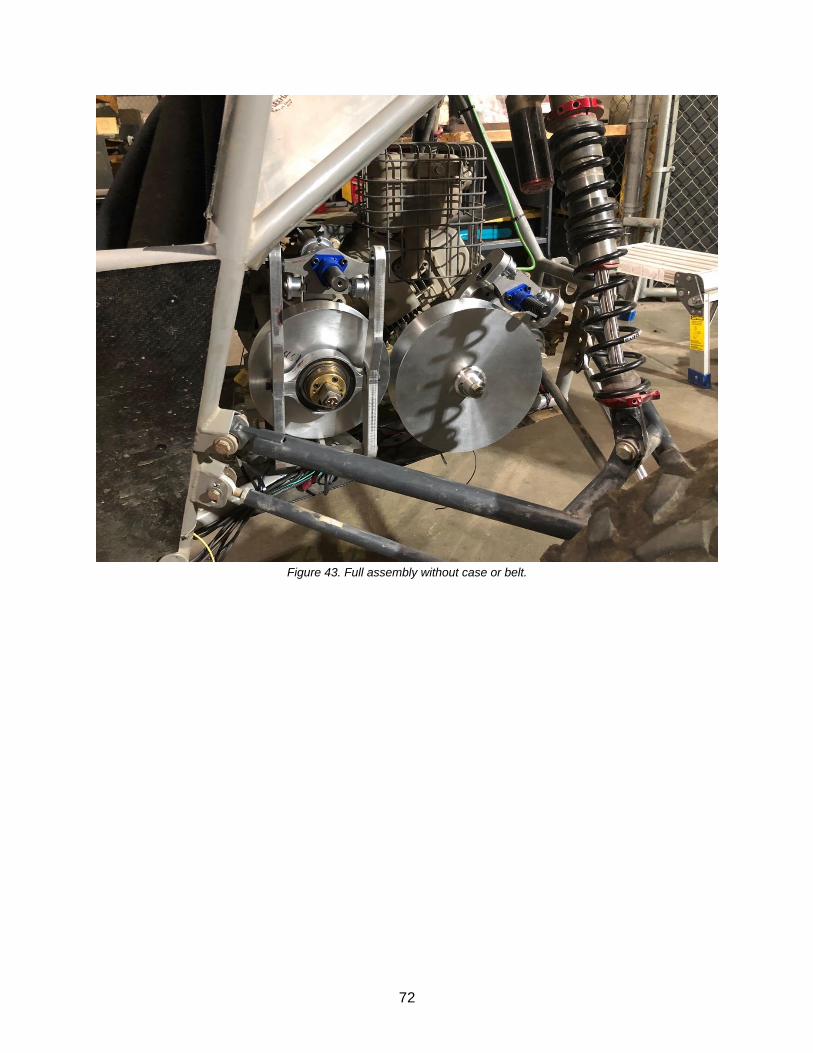
72
Figure 43. Full assembly without case or belt.

73
Figure 44. Second angle of assembled eCVT.

74
Table 9. Manufacturing analysis.
Component Processes Required Timeline
Sheaves CNC lathe, CNC Mill Begin build week, 100 hours to complete
all
Shafts CNC Lathe, CNC Mill (4th axis),
Coating, shaping splines (Secondary), Broaching keyway in blind hole (primary)
Begin build week, 100 hours to complete all
Arm Mounts CNC Mill Begin start of winter quarter, 20 hours to
complete all
Arms Waterjet, Manual Mill Begin start of winter quarter, 30 hours to
complete all
Other Parts Manual Machining, Various Hand
Processes Throughout build process
Case Waterjet, Press Brake, Slip Roll,
Welding, Hammering Complete during week four of winter
quarter, 80 hours
7. Design Verification The Design Verification Plan in Appendix 11.8 acts as a checking document to ensure that the
system currently being designed and manufactured is the same system that was originally
intended. To accomplish this, a description of tests and their accepted criteria has been
assembled to check the validity of the final design and verification of the final product.
Some tests are able to be conducted with the 3D model, primarily the ratio range test. In this test,
we will be measuring the ratio range with the current designed sheave pitch and travel. Hand
calculations have already suggested that the current design will allow the eCVT to achieve the
desired ratio range but going farther and testing the 3D model will give additional verification. The
tests have been split into two main groups that determine how crucial the test results are. The “All
Must Pass” target requirement is reserved for aspects of the eCVT system that are crucial for
operation of the eCVT. Tests that fall into this category include stiffness of the backing plate and
test arms. If these parts fail, the system would fail to actuate, rendering the eCVT useless.

75
Additionally, the eCVT will need to pass tests for weight and life. If the designed system cannot
achieve the desired life cycle, then major reconsiderations will need to be investigated.
The R90C90 rating (90% Reliability, 90% Certainty) describes the tests that are not as crucial as
the “All Must Pass”, yet still important to the overall performance of the eCVT. An example of this
is the temperature test, ensuring that the belt temperature does not exceed 180℉, as well as
checking for weather wear throughout the case after running the eCVT for a typical life cycle. In
the case where the belt does exceed 180℉ the strength of the belt would decrease, decreasing
the life of the belt, but only slightly affect the system performance. Similarly, weather wear
shouldn’t affect the performance of the system significantly but should be addressed if excessive
wear is noticed.
The majority of the tests will require the final product assembly for testing. These final product
tests will measure wear throughout the system after an extended life cycle. Certain system parts
will be checked for wear including sheaves, belt, and lead screw. Sheaves will be checked for
wear along the sheave’s face surface where the belt rides. If extensive wear is visible, additional
research into sheave coatings will need to be done. The lead screws and ball nut will also be
checked for any wear and increased sliding friction. If extensive wear and sliding friction is found,
research into other dry lube will be performed. Overall system performance will be tested once
the eCVT is assembled and integrated into the current Baja vehicle. The eCVT system will be
tested for acceleration and braking ability with results that should translate directly to the
competition results.
Unfortunately, our timeline for the design and manufacturing of this project became longer than
anticipated and stopped us from validating the performance of the eCVT. This was due to the
very large scope of the mechanical design and manufacturing as well as communication issues
with the controls team. The validation that we were able to do was all packaging related. The
system assembles together well and fits onto the car in the very tight spaces where it was
designed to go. Time constraints did not allow us to further validate the design.
8. Project Management
Beginning in the early stages of manufacturing, project management proved to be a challenge.
First, the final success of our project depended heavily on coordinating with an entirely separate
senior project. Secondly, the manufacturing experience of the team members varied wildly.
Overall, nine separate individuals with constantly changing availability needed to stay in sync for
nearly a year. Compounding these challenges were unexpected manufacturability issues and
delays with outsourced work. We recognize combinations of many or all of these challenges are
not uncommon in the business world, and as such we made our best efforts to drive the project
forward and overcome each challenge.
Our primary effort to stay coordinated was holding regular team meetings, in addition to
manufacturing time. When possible, meetings were held two to three times a week. In general,

76
this plan worked well. However, we should have coordinated the manufacturing efforts earlier
more often with the controls team and divided more tasks between both parties.
We made efforts to balance our different levels of manufacturing experience with our timeline. We
used simpler parts to give opportunities to increase manual machining skill to those with less
experience. Meanwhile, the more experienced team members tackled more advanced parts. This
balance proved effective and satisfactory.
8.1 Communication
Throughout the past year, most communication was kept internal amongst the two individual
design and control sub-teams that made up the Baja senior project team. Communication
between the two sub-teams was strong in the first quarter when input was needed from both sides
to determine the overall eCVT design. After PDR, the mechanical team moved forward with the
finer details of their design, and communication between the teams was still strong, yet less
frequent. The design team was able to receive input from the controls team whenever needed, in
addition to holding progress meetings every two to three weeks. As the manufacturing phase
approached and the design changes required by the controls team were implemented,
communication between the sub-teams grew to be even less frequent.
The controls team was not available during the manufacturing phase, stating that it was not
included in their scope of work and as a result, were not required to assist in the manufacturing
of the eCVT. This choice put the design team at a disadvantage; with the design finalized, we had
anticipated help from the controls team, as they had both knowledge and experience in the Baja
manufacturing process. However, it was their understanding that they would step in once the
eCVT was fully manufactured, as opposed to fully designed, and only then would they place the
respective sensors/motors onto the eCVT to begin the testing phase. To overcome this obstacle,
the design team opened up communication to other members of the Cal Poly Baja team with
machining experience to assist. We were very fortunate and grateful to have a handful of
members take an interest in the senior project and dedicate hours of their own time to assist the
design team; with their help we were able to stay on par with schedules and lead times. Despite
the 20 weeks of manufacturing time, once the mechanical system was manufactured, the sister
group was not ready to install their system onto the car and did not even have all parts in house.
It was extremely frustrating for members on the mechanical team to have the sister group not
assist in manufacturing, shirk the responsibility of manufacturing their own system, and blame the
extended timeline on the mechanical team’s inability to complete manufacturing without the
needed help.
8.2 Lessons Learned
As mentioned above, one of the more bothersome lessons learned was to give more time and
thought into the initial scope of work for both sub-teams, to prevent any miscommunications and
false assumptions in future phases. In addition to the controls team insisting that they were not

77
responsible for being involved throughout the design phase, there were some other discrepancies
in the original scope of work due to miscommunication. One example of this was agreement
between the design and controls team as to what the overall goals were for the eCVT. The design
team planned their work efforts and time management for the eCVT on the assumption that the
eCVT would be on the Baja vehicle and perform for a complete competition. However, it was
later found that the controls team needed to compromise on these goals. Instead, the controls
team began basing their efforts on achieving a bare minimum goal of getting the vehicle to travel
just 100 feet before coming to a rest. The lack of communication in the earlier phases between
the sub-teams gave reason for frustration in the later phases of the project. One lesson learned
would be to have everyone on both sub-teams able to fully plan out the scope of work in the initial
phase, so that there is an equal amount of work between both teams through the entirety of the
project.
Setting accurate time goals was another obstacle that came up multiple times throughout the
project, both internally within the design team and externally with the controls team and third-party
involvement. At certain points through the design phase, the design team was confident that they
would be able to achieve a certain goal by a certain date, only to be delayed by some unknown
factor. Once the Gantt chart was set up, we had a better understanding of realistic timelines for
each goal, accounting for unforeseen delays. There was also some overconfidence from the
control team, insisting that they would be able to install and debug the sensors in a single
afternoon once the design team had completed the manufacturing and assembly portion.
Unfortunately, this was not the case; even with the extended manufacturing time, the controls
team was not prepared for complete installation and set-up of the sensors and motors. It is to the
design team’s knowledge that incorrect parts were ordered and lead times for redelivery were
upwards of a week when time was crucial. In addition, the controls team was unable to perform
any on-vehicle testing of the eCVT until after the school year ended, which was saddening to both
teams. No team is to blame for the miscommunication and time delays, however a lesson learned
here is to be proactive, taking care of future tasks if there is downtime. Had the controls team
purchased the necessary parts for installation when the design team was in the manufacturing
phase, there would have been a faster transition of the eCVT from the design team to the controls
team, allowing for more time allocated for testing.
9. Conclusion
Designing and manufacturing the eCVT encompasses the mission statement of Cal Poly’s
Mechanical Engineering program. Throughout all phases of design, the design team was able to
apply what we had learned in our ME courses to this real-world application. Over the course of
the last year, we have been able to brainstorm, design, and manufacture what promises to be a
viable eCVT for the Baja vehicle; a process that has been challenging yet extremely rewarding to
all those involved. Although the designed eCVT did not make it onto the Baja vehicle in time for
competition, we feel as if we have achieved the objectives that were originally established. There
were times of challenge and late nights, however we feel that our team was able to come together
to push through, working towards the common goal.

78
Coincidentally, our senior project team was not the only Baja team to research the development
an electronically actuated CVT at this time; other schools including Arizona State University, ETS,
and Cal Poly Pomona have all attempted to design an eCVT for their respective Baja clubs. When
compared against these universities, we believe that we have the superior CVT design, boasting
a more compact and reliable design (based solely on calculations and simulations). We hope that
these advantages will lead to better performance throughout competitions.
To the next group that the torch is passed onto, we hope that we have given a detailed plan,
allowing an ease of transition for further improvements and ultimately success in the national
competitions. We have come a long way, starting with little to no knowledge of how the current
mechanical CVT operates, to exposition a year later presenting a fully functional electronically
actuated CVT. The design team was on the same page for the entire length of the project, with
little turmoil and great chemistry, a quality that is sometimes overlooked and undervalued.
10. References
[1] Nisentra, 2018. [Online]. Available: http://www.nisentra.com/structure_and_operation-703.html. [2] M. Ware, "GrabCad," 2015. [Online]. Available: https://grabcad.com/library/gaged-engineeringcustom-cvt-1. [Accessed 2018]. [3] O. Aaen, lav Aaen’s Clutch Tuning Handbook: For serious racers and anyone who wants more performance from their variable ratio belt-transmission, Racine, Wisconsin: Aaen Performance, 2015. [4] V. P. T. M. J. U. J. Lopas, "Testing CVT Final Report," 2015. [5] Sjvc.edu, "Subaru Lineartronic CVT Technical Training," ILYAZ tv, 14 September 2016. [Online]. Available: https://www.youtube.com/watch?v=v7GIqlb7NfA. [Accessed 2018]. [6] J. H. Gibbs, "Actuated Continuously Variable Transmission for Small Vehicles," 2009. [7] Society of Automotive Engineers, 2018. [8] T. McDermott, Interviewee, Senior Applications Engineer, SKF. [Interview]. 17 October 2018.

79
11. Appendices
11.1 Quality Function Deployment (QFD)

80
11.2 Concept Selection Decision Matrix

81
11.3 Table of Failure Modes

82
11.4 Preliminary Analysis and/or Testing Details
11.5 Concept Drawings
Renders of Central Lead Screw Design Concepts
Figure E.1: Central Lead Screw Through-Bolt Concept
Figure E.2: Central Lead Screw Outboard Sheave Actuated Concept

83
Figure E.3: Central Lead Screw Inboard Sheave Actuated Concept

84
11.6 Drawing Package
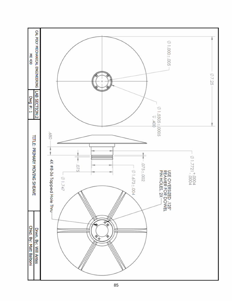
85

86

87

88

89

90
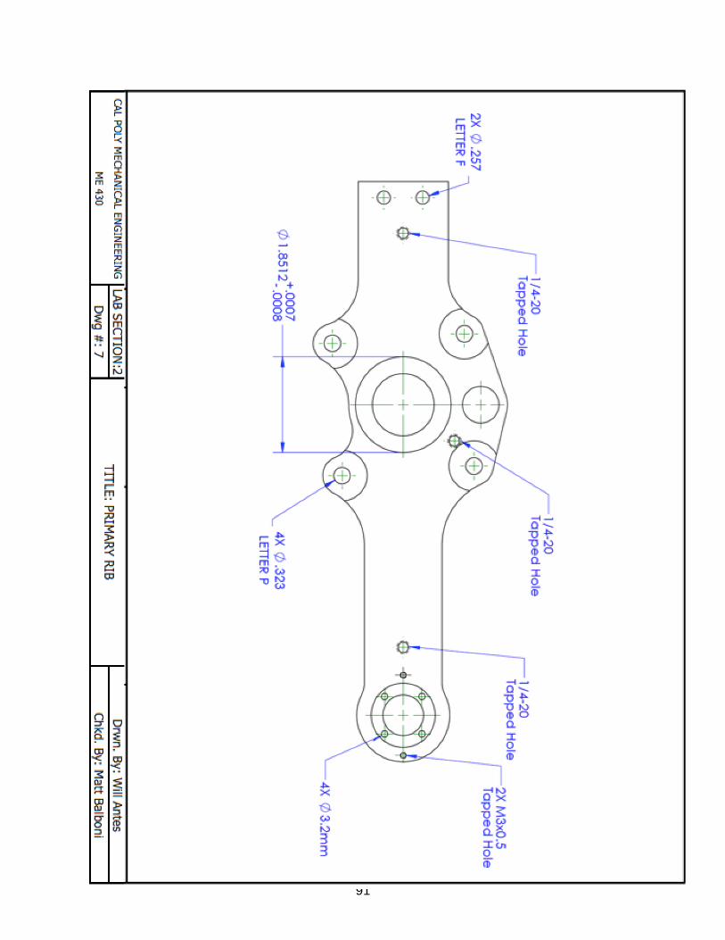
91

92

93
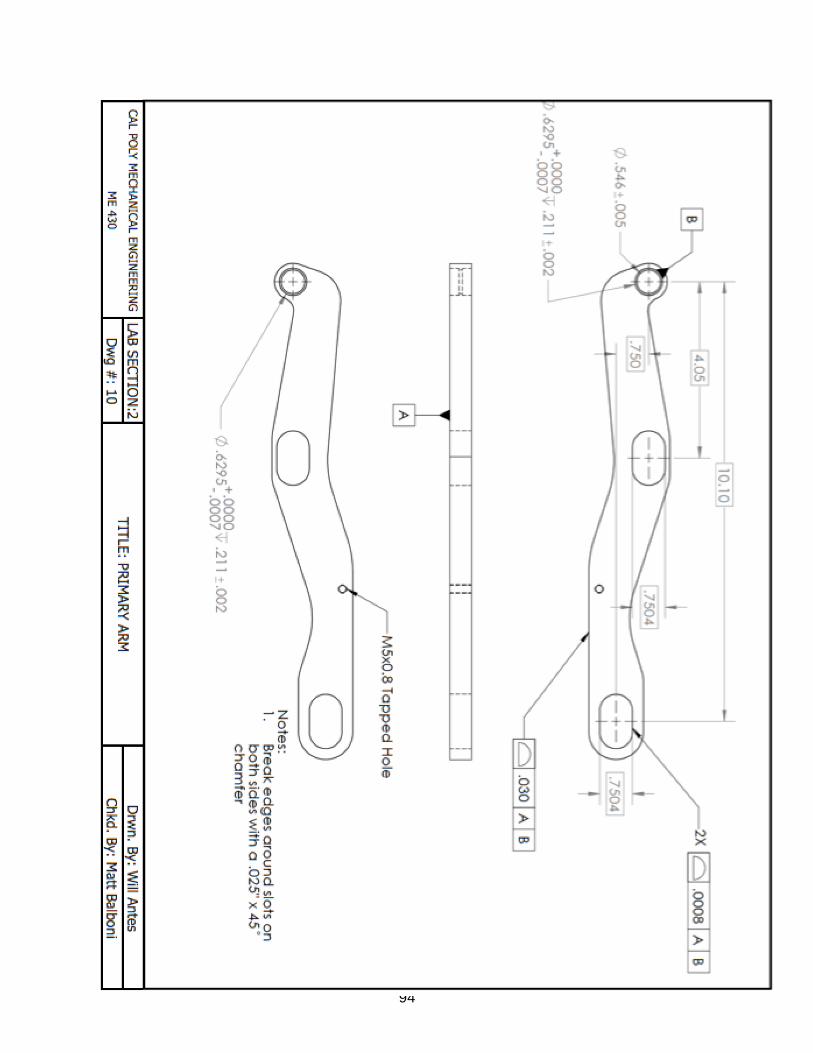
94

95

96

97

98
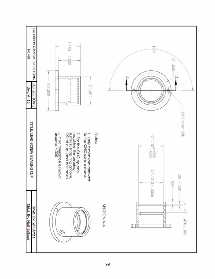
99

100
11.7 Bill of Materials/Hardware Order
Item Quantity Unit Cost (to team) Total Cost (to Team)
Sheave Stock 1 $0.00 $0.00
Aluminum Plate Stock 1 $173.08 $173.08
Primary Shaft 1 $75.76 $75.76
Drive Bushing Stock 2 $92.61 $185.22
Pivot Stock 1 $110.71 $110.71
Engine Shaft Spacer 1 $0.00 $0.00
Engine Standoffs 4 $0.00 $0.00
Reluctor Wheel 1 $0.00 $0.00
Hall Effect Standoff 1 $0.00 $0.00
Primary Carbon 1 $0.00 $0.00
Secondary Shaft Spacer 1 $0.00 $0.00
Gearbox Standoffs 2 $0.00 $0.00
Brace 1 $0.00 $0.00
Shift Fork Stock 1 $83.94 $83.94
Lead Screw End Cap 2 $0.00 $0.00
Bearing Cup 2 $0.00 $0.00
CVT Band 2 $55.53 $111.06
Case 1 $25.20 $25.20
Helix Lead Nut 8 $51.00 $408.00
Helix Lead Screw 4 $75.00 $300.00
Ball Rollers 12 $6.67 $80.04
Track Rollers 8 $20.57 $164.56
Internal Retaining Ring 1 $11.73 $11.73
External Retaining Rings 8 $7.26 $58.08
1/8" x 1/2" Dowel Pins 2 $0.00 $0.00
12-24 x 1/2" Cap Screws Lead Nut 6 $0.00 $0.00
8-36 x 1/2" Cap Screws Drive Bushing
8 $0.00 $0.00
Lead screw bearing 4 $0.00 $0.00 Low Profile 3mm x0.5 x16 Cap
Screw 10 $0.00 $0.00
4-48 x 3/4" Cap Screw Fixed Sheave to Shaft
8 $0.00 $0.00
28mm Internal Retaining Ring 1 $5.86 $5.86
1/4-20 Jam Nuts 8 $0.00 $0.00

101
4-40 x 1/4" Flanged Cap Screw 8 $3.32 $26.56
3/8"-24 x 4" Engine Bolt 1 $0.00 $0.00 Low Profile 1/4"-20 x 1" Cap
Screw 1 $0.00 $0.00
M1.5 Dowel Pins 2 $0.00 $0.00
5mm x 20mm Flanged Cap Screw 2 $9.41 $18.82
Pivot Bearing Spacer 1 $11.41 $11.41
Pivot Bearing Shims 1 $12.26 $12.26
5mm x 10mm Flanged Cap Screw 1 $8.45 $8.45
1/4"-20 x 3/4" Cap Screws Pivot to Crosslink
4 $0.00 $0.00
8-36 x 5/8" Cap Screw Drive Bushing
4 $0.00 $0.00
3/8"-16 x 3" Gearbox Bolt 1 $0.00 $0.00
5/16"-18 Engine/Gearbox Helicoils 10 $0.00 $0.00
M12-1.75 Jam Nut for Lead Screw 2 $0.00 $0.00
1/4"-20 x 3/4" Cap Screws Carbon Fasteners
4 $0.00 $0.00
Lead Screw Bearing Spacer 16 $2.06 $32.96
Pivot Bearings 8 $0.00
Shift Fork Bearing 2 $0.00
Thrust Bearing 1 $0.00
Gates Belt 1 $71.10 $71.10
Sum: $1,974.80
MESFAC Mechanical Team Funding: $863.83
Cost to team: $1,110.97

102
11.8 DFMEA
Item/Function Potential
Failure
Modes
Potential Effects of Failure
Severity (1-10)
Potential Causes/Mechanisms
of Failure
Probability (1-10)
Det (1-10)
RPN (S*P*D)
Recommended Actions
Arms Bending Inaccurate
shifting, jams and
won’t shift
5 Excessive force,
manufacturing
inaccuracies,
improper handling, FOD
3 7 105 Leave clearance
in other aspects
of design to
allow for thicker, stiffer arms if
needed
Arm Bushings Excessiv
e Wear
Inaccurate
Shifting, binding
5 Improper
maintenance, FOD
6 7 210 Check bushings
frequently,
replace if worn
Arm Bushings FOD
jamming
bushings
No shift
condition, bad for
motor/gearbox
8 Bad case sealing 4 6 192 Ensure proper
case seal
Square
Bushing
Excessiv
e Wear
Inefficient, could
jam and not shift
4 Improper
maintenance, lack of dry lube, using parts
past design life,
improper
manufacturing
tolerances
10 9 360 Inspect bushing
assembly frequently,
replace worn
components.
Ensure proper
case seal to mitigate FOD
which causes
accelerated wear.
Sheave Bending Bad vibes,
inefficient
4 Improper part
handling, FOD, too much clamping
force
3 10 120 Ensure proper
sheave handling
Sheave Poor
Surface
Finish
Inefficient,
excessive heat
buildup, bad shifting
4 FOD, improper
manufacturing,
improper handling
9 10 360 Ensure proper
sheave handling,
ensure proper case seal to
mitigate FOD
damage
Sheave
retaining bolts
Back out Sheave falls off 9 Improper assembly,
excessive vibrations
5 10 450 Use Loctite on
fasteners
Main holding
bolt
Backing
off
CVT falls off 9 Improper assembly,
bad vibrations
5 10 450 Use Loctite on
bolt
ACME screw Bending Slight shifting
inaccuracies
8 Improper handling,
loading outside
designed cases
4 10 320 Have spare
leadscrews
ACME screw Too
much
backlash
Shifting
inaccuracies
4 Excessive wear,
lack of maintenance
3 4 48 Use anti-backlash
nut, check it
frequently for
wear
ACME screw Jams No shift condition
9 FOD, manufacturing
tolerances
6 4 216 Ensure proper case seal to
mitigate FOD

103
Main Bearing Excessiv
e Slop
Shifting
inaccuracies, not enough clamping
force
6 Improper
maintenance, using part past design life,
FOD
4 8 192 Check bearing
frequently for wear, replace if
worn
Main Bearing Seizes Arms try to rotate
with sheaves
10 FOD, using part
past design life,
excessive heat
4 5 200 Check bearing
frequently for
wear, replace if worn
Motor/Electric
al
Gremlins No shift 10 Programming, poor
wiring, etc.
10 5 500 Ensure proper
wire routing,
ensure Controls
CRU does their jobs

104
11.8 Design Verification Plan