Embed Size (px)
Citation preview
1
FRP Composites for Bridge Decks and Superstructures: State of the Practice in the U.S.
Lou Triandafilou, P.E. Senior Structural Engineer Federal Highway Administration, Eastern Resource Center 10 S. Howard Street, Suite 4000 Baltimore, MD 21201-2532 [email protected]
Jerome S. O’Connor, P.E., F. ASCE MCEER Senior Program Officer, Transportation Research University at Buffalo, The State University of New York 115 Red Jacket Quadrangle Buffalo, NY 14261-0052 [email protected]
ABSTRACT
In the U.S., fiber reinforced polymer (FRP) composite materials have been in service on public infrastructure facilities as bridge decks and superstructures for over ten years. While the structural performance of these 100+ bridges has generally been satisfactory, some issues have given bridge owners and their consultant engineers reason to hold back a on wider acceptance and use of these new materials. Here the authors give some specific examples of completed projects, explain the deficiencies that need to be explored further before composites can compete with conventional materials, and point to some promising technologies that may spark a renewed interest in these materials. Keywords: (FRP, composites, bridge deck, accelerated bridge construction)
2
BIOGRAPHICAL NOTES
Mr. Lou Triandafilou, PE, a graduate of Rutgers University, serves on Federal Highway Administration’s Structures Team, specializing in technology transfer related to accelerated bridge construction strategies and the use of high performance materials such as FRP composites, HP concrete and steel, and corrosion-resistant rebar. At FHWA’s Resource Center, he brings together FHWA Divisions, State DOTs, industry, and academia partners by chairing and participating in multi-jurisdictional committees.
Mr. O’Connor, PE, F, ASCE, a graduate of Rensselaer, is Senior Program Officer, Transportation Research at MCEER, University at Buffalo. He initiated and completed over 15 FRP demonstration projects, served as panel member on NCHRP Project 04-27, Application of Advanced Composites to Highway Infrastructure -Strategic Plan and is on FHWA’s Virtual Teams for FRP composites. He has authored 65+ papers on bridge safety assurance, load testing, bridge inspection, and the use of composite materials for bridges.
3
SECTION I INTRODUCTION
1.1 National Need for Better Infrastructure In June 2009, James Oberstar, Chairman of the Congressional Committee on Transportation and Infrastructure issued a document on the Surface Transportation Authorization Act of 2009, a Blueprint for Investment and Reform. This transportation bill is a vital component for the renewal of the country’s highway infrastructure. It is important not only because of the deteriorated condition of our aging roads and bridges, but also because of the financial challenges associated with it. In his report, it is estimated that there is a backlog of at least $32.1 billion for bridge1 work on the National Highway System (NHS)2. The horizon appears challenging as one considers that most existing highway bridges were designed for a 50-year design life but their average age is 43 years3. While the current AASHTO Bridge Design Specification calls for a 75-year life, the majority of the 601,396 bridges in the National Bridge Inventory (NBI) were not built to that standard. According to the Oberstar report, 71,461 or nearly 12% of all bridges in the U.S. are classified as structurally deficient. In addition, 79,933 bridges (over 13%) are functionally obsolete.4 The deck of a bridge is particularly vulnerable to degradation because of its exposure to the elements and direct contact with vehicular wheel loads. In fact, the NBI lists 23,542 bridges (~ 4%) that have a deck rated “poor” or worse.5 Attention needs to be given to these bridges in the immediate future or there may be safety risks to the traveling public. Fortunately, deck failures are usually not catastrophic since what materializes is a “punch-through”. This presents itself as a safety issue commanding immediate attention but is not a tragic collapse. The de facto standard for bridge decks is reinforced concrete, with 88% of bridges using concrete. Despite its widespread acceptance, there is ample evidence that the performances of decks built prior to the use of rebar corrosion protection measures or prior to the use of high performance concrete is not entirely satisfactory. From the authors’ experience, cracking and spalling is all too common in this category of decks. Recognition of the deficiencies of traditional materials hints at the need to investigate the use of different materials and methods. 1.2 Benefits of Using Composites Fiber Reinforced Polymer Composite (FRP) composite decks have intrinsic characteristics that make them well suited to FHWA’s “Bridge of the Future”. These are: 1 According to National Bridge Inspection Standards (NBIS) in 23CFR650.3, a structure must have a span exceeding 20 feet (6.1 meters) in order to be classified as a bridge. 2 The National Highway System (NHS) is a road network of 160,000 miles that includes the Interstate Highway System, as well as other roads important to the nation's economy, defense, and mobility. 3 1966 was the average year built as of 12/08, per 7/27/09 e-mail correspondence with Ann Shemaka, FHWA 4 Structurally deficient and functionally obsolete are precisely defined terms used in the NBI. 5 Bridges with a deck rated of 4 or less per NBI 12/08.
4
o Life cycle cost is a fraction of the current expectation. o Construction time is a fraction of the current time. o Material degradation is no longer an issue. o It is immune to attack from floods and earthquakes. o A total systems approach is used in their design o Adaptable to new demands o Reduced carbon footprint (this criterion was added by the authors)
FRP decks are modular systems that are light6 yet strong enough for any legal or permit load. They are relatively easy to install, and can be done in a few days instead of months. They have the potential to last much longer than other types of deck because they are corrosion-resistant. The quality of the finished product is better than a site built deck because the deck components are manufactured in a factory environment, frequently using strict ISO-9001 quality assurance criteria. The work is done under repetitive, controlled conditions according to the shops’ quality assurance and safety practices. Specific scenarios are listed below where the technology is applicable and beneficial.
Table 1. Scenarios where composites are beneficial
o Removing an existing concrete deck with asphalt overlays can significantly reduce the dead load. This translates directly to an increase in live load capacity and frequently allows the removal of weight restrictions.
o New project alternatives become available because bridges that previously would have been completely replaced can now be cost effectively rehabilitated with the installation of a light-weight, durable deck. If a steel bridge beam has some section loss due to rust, switching to a lighter deck can help compensate for the loss of strength in the reduced section.
o Environmental impact can be reduced by rehabilitating vs. replacing. A deck replacement project done as part of a light rehabilitation project has a much more restricted scope and therefore smaller carbon footprint. For instance, the limits of the job can be from “bridge joint to bridge joint,” rather than well into the roadway approaches. Furthermore, fewer permits or permit restrictions can help keep a project on schedule and help it progress faster.
o Prefabrication reduces the time on-site, thereby reducing exposure time to workers and the traveling public, mitigating risk and improving safety.
o Rapid construction is possible with modular construction. The components are made off site, reducing the time required on the job for assembly. The need for cure time is virtually eliminated. Fabrication in a plant can also be done in any kind of weather, whereas on-site deck construction can be slowed and delayed by inclement weather. Fabrication under factory conditions lends itself to better quality control too.
6 Unit weight < 25 psf vs. ~100 psf for reinforced concrete
5
Table 1. Scenarios where composites are beneficial
o Rapid construction reduces cost and inconvenience experienced by the traveling public. In addition, less air and noise pollution is produced, and less fuel is consumed from slowing, stopping or detouring traffic. The cost of Maintenance and Protection of Traffic (MPT) is often significantly reduced.
o When an old bridge needs a new deck, it is typically taken out of service for at least a month to allow time to place the concrete and wait for it to cure. In high traffic areas, this frequently causes traffic congestion and increases the risk of an accident for travelers and workers for the duration of the construction project.
o Service life of a structure can be extended with relatively minor work. For smaller bridges, deck replacement is so easy that the project can be administered and executed as a maintenance task instead of major bridge rehabilitation. The lightweight and modular nature may make it feasible to do work with in-house forces instead of contracting out. Lighter cranes and smaller crews are needed.
o A bridge can be modified to accommodate pedestrians without significantly adding dead load e.g. adding a cantilevered sidewalk.
o Changing from an open grate deck to a watertight FRP deck provides protection to the steel flooring system previously exposed to the elements. Keeping deicing salts and debris off the steel will significantly increase the expected life of the structure.
o For moveable bridges, requirements for mechanical systems will be reduced because there will be less mass to lift or swing. The 856 moveable bridges in the country (bascule, swing and lift bridges) need to use a lightweight type of deck. Open steel grating and timber have been used but not without problems that result in short service. Steel grating not only rusts and frequently suffers from fatigue cracking of welded connections; but also allows roadway drainage and deicing chemicals direct contact to the steel superstructure. Timber decks also deteriorate prematurely because they have a tendency to check and rot.
o Usually, the smaller the scope of the project, the sooner it can be initiated. Thus, a rehabilitation that addresses a posting problem provides the public with a solution to their problem sooner that a bridge replacement would (sometimes several years sooner).
o In regions where earthquakes present a hazard, a reduction of structure mass can ease inertial demands that need to be accommodated.
o Since the average life of a concrete deck is less than that of the, it will need to be replaced at least once before during the life of the bridge. New composite materials are sufficiently durable that they can be designed to last the entire life of the structure. Avoiding unnecessary construction projects over the service life of a bridge inconveniences the public less and reduces its carbon footprint because there is less pollution, fuel consumption, etc.
1.3 Current Disadvantages of Composites
6
Although fiber reinforced polymer (FRP) composite decking is a viable option for highway bridges, there are still some remaining issues to be addressed:
o Cost: The initial unit cost of an FRP deck
o Supply & Demand: There are few suppliers of FRP bridge decks. Demand has been intermittent, making it difficult for suppliers to remain in business and be profitable.
o Sole Source: FRP deck systems that are on the market today are proprietary systems. Repeatedly specifying and/or purchasing the sole source products is contrary to the regulations and policies of most government agencies, which complicates their typical contracting practices.
o Technical: Although the decks used to date have generally performed satisfactorily, there have been some technical issues associated with implementing this new technology. Some of these problems will be presented later in this paper.
7
SECTION II HISTORY
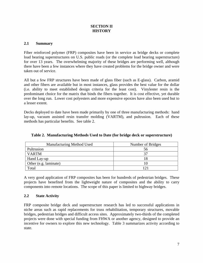
2.1 Summary Fiber reinforced polymer (FRP) composites have been in service as bridge decks or complete load bearing superstructures on U.S. public roads (or the complete load bearing superstructure) for over 13 years. The overwhelming majority of these bridges are performing well, although there have been a few instances where they have created problems for the bridge owner and were taken out of service. All but a few FRP structures have been made of glass fiber (such as E-glass). Carbon, aramid and other fibers are available but in most instances, glass provides the best value for the dollar (i.e. ability to meet established design criteria for the least cost). Vinylester resin is the predominant choice for the matrix that binds the fibers together. It is cost effective, yet durable over the long run. Lower cost polyesters and more expensive epoxies have also been used but to a lesser extent. Decks deployed to date have been made primarily by one of three manufacturing methods: hand lay-up, vacuum assisted resin transfer molding (VARTM), and pultrusion. Each of these methods has particular benefits. See table 2.
Table 2. Manufacturing Methods Used to Date (for bridge deck or superstructure)
Manufacturing Method Used Number of Bridges Pultrusion 56 VARTM 37 Hand Lay-up 18 Other (e.g. laminate) 10 Total 121
A very good application of FRP composites has been for hundreds of pedestrian bridges. These projects have benefited from the lightweight nature of composites and the ability to carry components into remote locations. The scope of this paper is limited to highway bridges. 2.2 State Activity FRP composite bridge deck and superstructure research has led to successful applications in niche areas such as rapid replacements for truss rehabilitation, temporary structures, movable bridges, pedestrian bridges and difficult access sites. Approximately two-thirds of the completed projects were done with special funding from FHWA or another agency, designed to provide an incentive for owners to explore this new technology. Table 3 summarizes activity according to state.
8
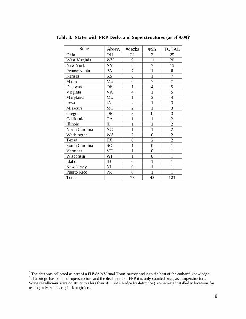
Table 3. States with FRP Decks and Superstructures (as of 9/09)7
State
Abrev. #decks #SS TOTAL Ohio OH 22 3 25 West Virginia WV 9 11 20 New York NY 8 7 15 Pennsylvania PA 7 1 8 Kansas KS 6 1 7 Maine ME 0 7 7 Delaware DE 1 4 5 Virginia VA 4 1 5 Maryland MD 1 3 4 Iowa IA 2 1 3 Missouri MO 2 1 3 Oregon OR 3 0 3 California CA 1 1 2 Illinois IL 1 1 2 North Carolina NC 1 1 2 Washington WA 2 0 2 Texas TX 0 2 2 South Carolina SC 1 0 1 Vermont VT 1 0 1 Wisconsin WI 1 0 1 Idaho ID 0 1 1 New Jersey NJ 0 1 1 Puerto Rico PR 0 1 1 Total8 73 48 121
7 The data was collected as part of a FHWA’s Virtual Team survey and is to the best of the authors’ knowledge 8 If a bridge has both the superstructure and the deck made of FRP it is only counted once, as a superstructure. Some installations were on structures less than 20’ (not a bridge by definition), some were installed at locations for testing only, some are glu-lam girders.
9
SECTION III BRIDGE DECKS
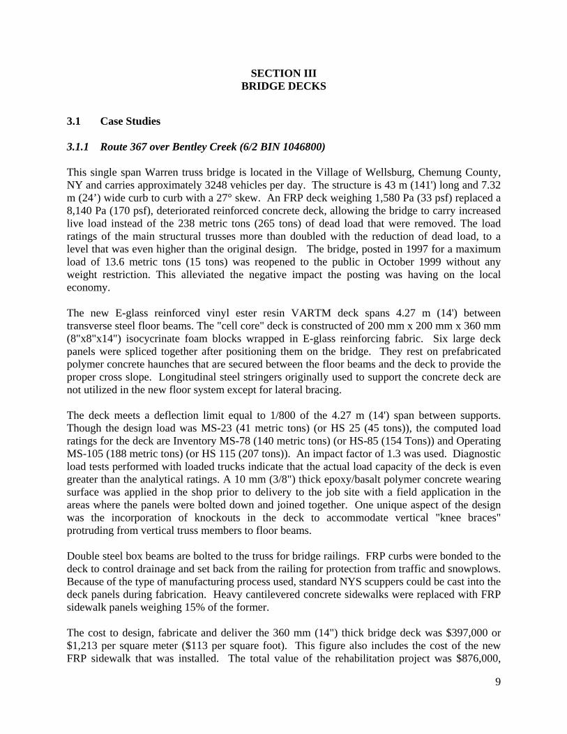
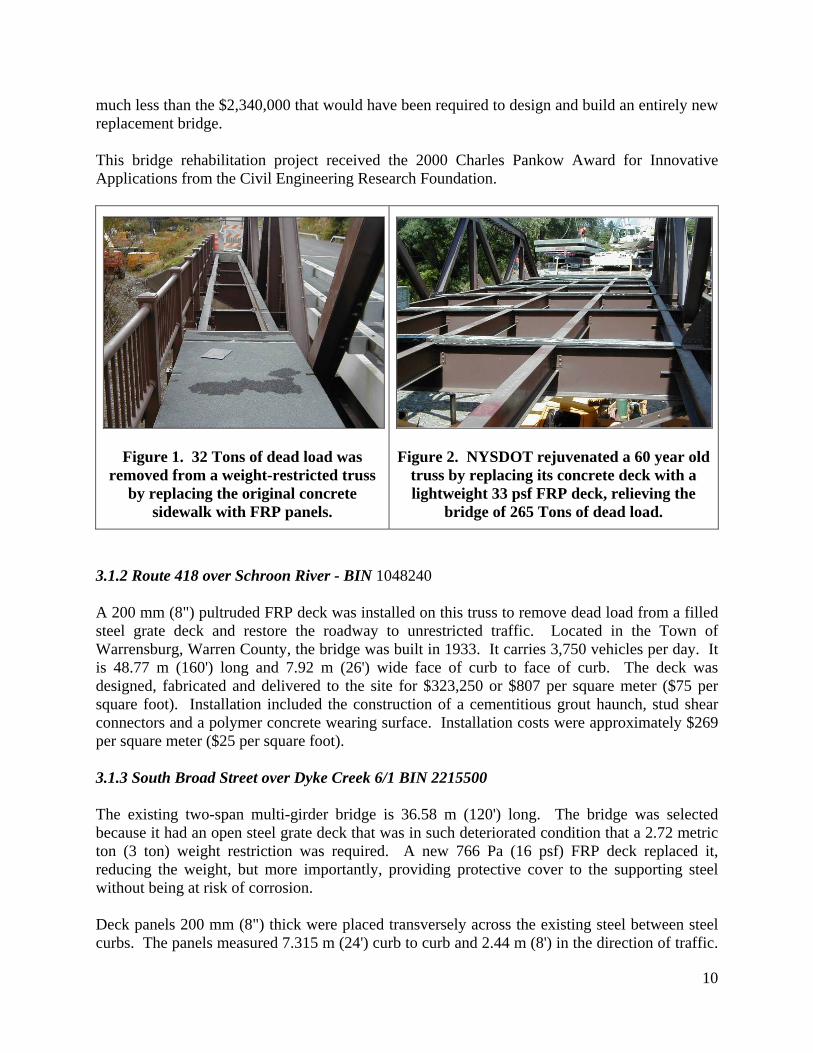
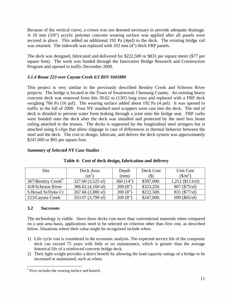
3.1 Case Studies 3.1.1 Route 367 over Bentley Creek (6/2 BIN 1046800) This single span Warren truss bridge is located in the Village of Wellsburg, Chemung County, NY and carries approximately 3248 vehicles per day. The structure is 43 m (141') long and 7.32 m (24’) wide curb to curb with a 27° skew. An FRP deck weighing 1,580 Pa (33 psf) replaced a 8,140 Pa (170 psf), deteriorated reinforced concrete deck, allowing the bridge to carry increased live load instead of the 238 metric tons (265 tons) of dead load that were removed. The load ratings of the main structural trusses more than doubled with the reduction of dead load, to a level that was even higher than the original design. The bridge, posted in 1997 for a maximum load of 13.6 metric tons (15 tons) was reopened to the public in October 1999 without any weight restriction. This alleviated the negative impact the posting was having on the local economy. The new E-glass reinforced vinyl ester resin VARTM deck spans 4.27 m (14') between transverse steel floor beams. The "cell core" deck is constructed of 200 mm x 200 mm x 360 mm (8"x8"x14") isocycrinate foam blocks wrapped in E-glass reinforcing fabric. Six large deck panels were spliced together after positioning them on the bridge. They rest on prefabricated polymer concrete haunches that are secured between the floor beams and the deck to provide the proper cross slope. Longitudinal steel stringers originally used to support the concrete deck are not utilized in the new floor system except for lateral bracing. The deck meets a deflection limit equal to 1/800 of the 4.27 m (14') span between supports. Though the design load was MS-23 (41 metric tons) (or HS 25 (45 tons)), the computed load ratings for the deck are Inventory MS-78 (140 metric tons) (or HS-85 (154 Tons)) and Operating MS-105 (188 metric tons) (or HS 115 (207 tons)). An impact factor of 1.3 was used. Diagnostic load tests performed with loaded trucks indicate that the actual load capacity of the deck is even greater than the analytical ratings. A 10 mm (3/8") thick epoxy/basalt polymer concrete wearing surface was applied in the shop prior to delivery to the job site with a field application in the areas where the panels were bolted down and joined together. One unique aspect of the design was the incorporation of knockouts in the deck to accommodate vertical "knee braces" protruding from vertical truss members to floor beams. Double steel box beams are bolted to the truss for bridge railings. FRP curbs were bonded to the deck to control drainage and set back from the railing for protection from traffic and snowplows. Because of the type of manufacturing process used, standard NYS scuppers could be cast into the deck panels during fabrication. Heavy cantilevered concrete sidewalks were replaced with FRP sidewalk panels weighing 15% of the former. The cost to design, fabricate and deliver the 360 mm (14") thick bridge deck was $397,000 or $1,213 per square meter ($113 per square foot). This figure also includes the cost of the new FRP sidewalk that was installed. The total value of the rehabilitation project was $876,000,
10
much less than the $2,340,000 that would have been required to design and build an entirely new replacement bridge. This bridge rehabilitation project received the 2000 Charles Pankow Award for Innovative Applications from the Civil Engineering Research Foundation.
Figure 1. 32 Tons of dead load was removed from a weight-restricted truss
by replacing the original concrete sidewalk with FRP panels.
Figure 2. NYSDOT rejuvenated a 60 year old truss by replacing its concrete deck with a lightweight 33 psf FRP deck, relieving the
bridge of 265 Tons of dead load.
3.1.2 Route 418 over Schroon River - BIN 1048240 A 200 mm (8") pultruded FRP deck was installed on this truss to remove dead load from a filled steel grate deck and restore the roadway to unrestricted traffic. Located in the Town of Warrensburg, Warren County, the bridge was built in 1933. It carries 3,750 vehicles per day. It is 48.77 m (160') long and 7.92 m (26') wide face of curb to face of curb. The deck was designed, fabricated and delivered to the site for $323,250 or $807 per square meter ($75 per square foot). Installation included the construction of a cementitious grout haunch, stud shear connectors and a polymer concrete wearing surface. Installation costs were approximately $269 per square meter ($25 per square foot). 3.1.3 South Broad Street over Dyke Creek 6/1 BIN 2215500 The existing two-span multi-girder bridge is 36.58 m (120') long. The bridge was selected because it had an open steel grate deck that was in such deteriorated condition that a 2.72 metric ton (3 ton) weight restriction was required. A new 766 Pa (16 psf) FRP deck replaced it, reducing the weight, but more importantly, providing protective cover to the supporting steel without being at risk of corrosion. Deck panels 200 mm (8") thick were placed transversely across the existing steel between steel curbs. The panels measured 7.315 m (24') curb to curb and 2.44 m (8') in the direction of traffic.
11
Because of the vertical curve, a crown was not deemed necessary to provide adequate drainage. A 10 mm (3/8") acrylic polymer concrete wearing surface was applied after all panels were secured in place. This added an additional 192 Pa (4psf) to the deck. The existing bridge rail was retained. The sidewalk was replaced with 102 mm (4") thick FRP panels. The deck was designed, fabricated and delivered for $222,500 or $831 per square meter ($77 per square foot). The work was funded through the Innovative Bridge Research and Construction Program and opened to traffic December 2000. 3.1.4 Route 223 over Cayuta Creek 6/2 BIN 1041880 This project is very similar to the previously described Bentley Creek and Schroon River projects. The bridge is located in the Town of Swartwood, Chemung County. An existing heavy concrete deck was removed from this 39.62 m (130') long truss and replaced with a FRP deck weighing 766 Pa (16 psf). The wearing surface added about 192 Pa (4 psf). It was opened to traffic in the fall of 2000. Four NY standard steel scuppers were cast into the deck. The end of deck is detailed to prevent water from leaking through a joint onto the bridge seat. FRP curbs were bonded onto the deck after the deck was installed and protected by the steel box beam railing attached to the trusses. The decks is supported by the longitudinal steel stringers but is attached using S-clips that allow slippage in case of differences in thermal behavior between the steel and the deck. The cost to design, fabricate, and deliver the deck system was approximately $247,000 or $65 per square foot. Summary of Selected NY Case Studies
Table 4: Cost of deck design, fabrication and delivery
Site Deck Area (m2)
Depth (mm)
Deck Cost ($)
Unit Cost ($/m2)
367/Bentley Creek9 327.60 (3,525 sf) 360 (14") $397,000. 1,212 ($113/sf) 418/Schroon River 386.62 (4,160 sf) 200 (8") $323,250. 807 ($75/sf) S.Broad St/Dyke Cr 267.66 (2,880 sf) 200 (8") $222,500. 831 ($77/sf) 223/Cayuta Creek 353.07 (3,799 sf) 200 (8") $247,000. 699 ($65/sf) 3.2 Successes The technology is viable. Since these decks cost more than conventional materials when compared on a unit area basis, applications need to be selected on criterion other than first cost, as described below. Situations where their value might be recognized include when: 1) Life cycle cost is considered in the economic analysis. The expected service life of the composite
deck can exceed 75 years with little or no maintenance, which is greater than the average historical life of a reinforced concrete bridge deck.
2) Their light weight provides a direct benefit by allowing the load capacity ratings of a bridge to be increased or maintained, such as when:
9 Price includes the wearing surface and haunch.
12
a) A bridge was originally designed for a lightweight deck. FRP will allow the bridge to carry the same live loads without continuing problems associated with open grate decks.
b) Additional dead load has been added over the years. The dead load from the original deck and overlays can be “traded in” for live load capacity.
c) There is reduced capacity in the steel superstructure due to section loss. Using a light deck can allow the same loads to be carried without having to strengthen members weakened by loss of cross section.
d) Weight savings can lead to decreased operating expense, e.g. movable bridges. e) Switching from a heavy deck to a lightweight deck can increase load capacity to compensate
for loading that was not anticipated during design. 3) The deck can be used to protect the flooring system from water and salt. 4) Speedy construction results in
a) Shorter need for maintenance and protection of traffic schemes. b) Decreased user cost (e.g. fuel costs, value of time).
Currently, the technology is most suitable for the following:
o Trusses o Historic structures o Bridges originally designed for light loads o Bridges to be widened o Bridges where the superstructure is in good condition but the deck is poor o Bridges that can be rehabilitated with a complete FRP superstructure and the abutments
are salvageable o Bridges where a low dead load is desirable o Moveable bridges o Emergency bridges and temporary, rapidly deployed bridges
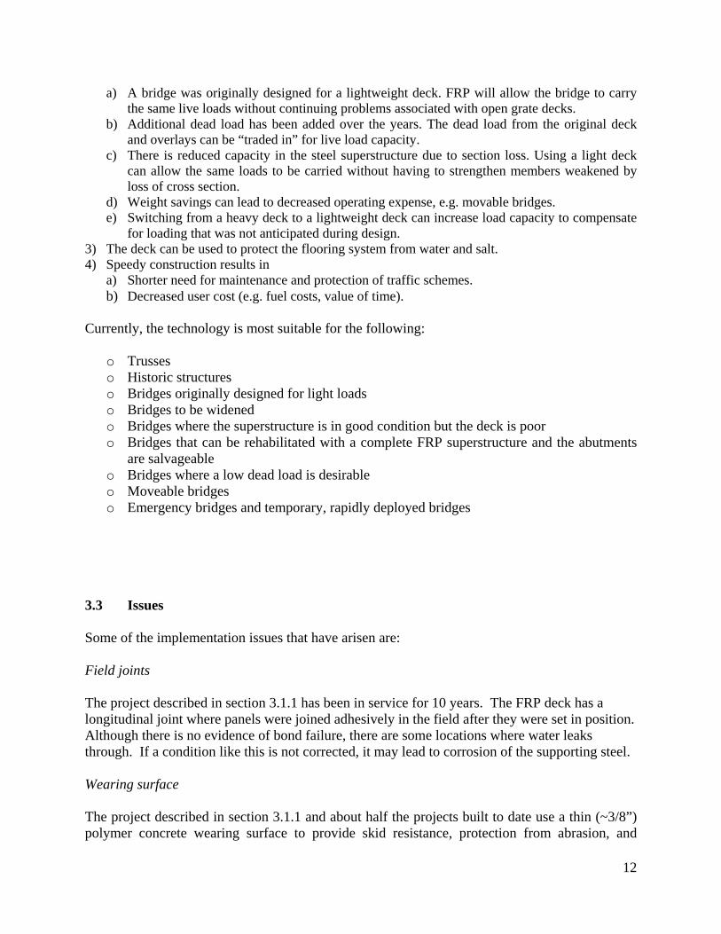
3.3 Issues Some of the implementation issues that have arisen are: Field joints The project described in section 3.1.1 has been in service for 10 years. The FRP deck has a longitudinal joint where panels were joined adhesively in the field after they were set in position. Although there is no evidence of bond failure, there are some locations where water leaks through. If a condition like this is not corrected, it may lead to corrosion of the supporting steel. Wearing surface The project described in section 3.1.1 and about half the projects built to date use a thin (~3/8”) polymer concrete wearing surface to provide skid resistance, protection from abrasion, and
13
ultraviolet (UV) protection. Some projects employ an asphalt layer for the same purpose. On the Bentley Creek bridge and several other projects, the wearing surface has cracked or even debonded from the FRP surface. Though not structural in nature, this has created a maintenance problem for bridge owners. The cause of these problems stems improper surface preparation, insufficient mixing of resins, thermal incompatibilities between surfaces, incompatibilities in elastic modulus, or an underlying issue with an adhesive joint that has reflected up through the wearing surface.
Figure 3. Sections of the polymer concrete wearing surface debonded from the FRP deck. These are photos of Bentley Creek but it has occurred on other bridges as well.
Connections Decks can be designed to act “compositely” with the supporting steel support members by using a stud shear connector, grouted to simulate a conventional concrete deck connection. If this method is used as was done for the project described in section 3.1.2, care must be taken to insure that the two materials are designed and constructed to act in unison; otherwise, the grout pocket can deteriorate, loosening the connection and introducing stresses into the deck that were unanticipated. Alternatively, the decks can be installed like a timber deck (as was done on the bridge described in section 3.1.3), using clips to hold them to the stop flange of a steel girder. This method can accommodate slip along the horizontal surface between the deck and the beam. The relative displacement is minor but allows the two components to act independently. Haunch Decks typically rest on a material such a grout or a neoprene pad rather than directly on the structural steel. This area ensures uniform support and accounts for variations between the elevations of adjacent beams. How to construct a functional and durable haunch has presented challenges on some past projects.
14
Bridge railing Because of the potential liability issues that would result from variance from national standards, providing a tested bridge railing system is critical. Past demonstrations have been able to avoid railing issues by attaching the railing to the fascia of the bridge railing or on the face of the truss in the case of a truss bridge. Nationally adopted deck design specifications Researchers have developed specifications in the form of acceptance criteria. These have been formally submitted to the AASHTO Subcommittee on Bridges and Structures (SBOBS) Technical Committee T-6 on FRP Composites, for evaluation and resolution of comments that were provided by state DOT members and industry.
15
SECTION IV SUPERSTRUCTURES
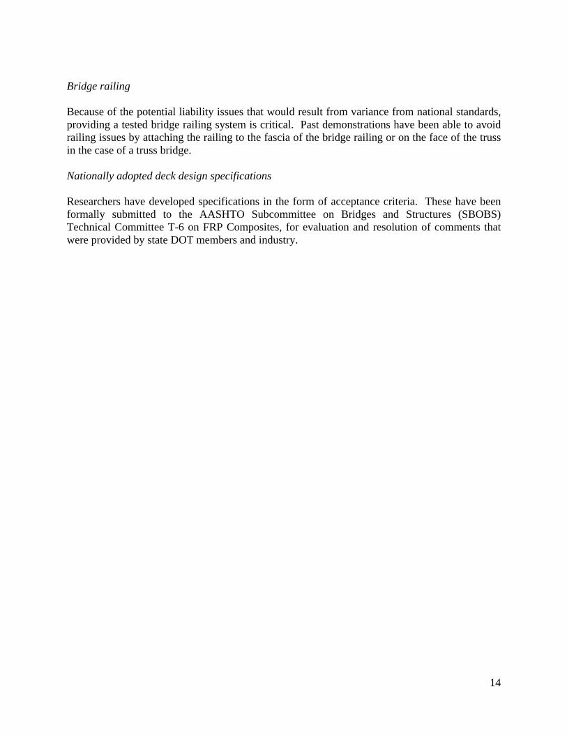
4.1 Case Studies 4.1.1 Case Study: NY248 over Bennetts Creek, Steuben County, NY (Figure 4) In this case, a severely deteriorated concrete slab bridge, built in 1926 and posted at 10 Tons, was removed and replaced with an all-composite superstructure. A bridge maintenance crew that was not accustomed to doing this type of work easily accomplished the project and the installation of the superstructure took just a few hours. The replacement bridge arrived at the site on a truck in two pieces, and placed on reconstructed abutments. The final wearing surface came pre-applied, as did composite stay-in-place forms for a concrete barrier. The objective of the project was to replace the deteriorated bridge on a compressed time schedule using in-house DOT maintenance forces. The 24-inch deep FRP superstructure consists of two skewed panels that were joined along the centerline of the road with a shear key and adhesive grout, providing load transfer between them. A crown was provided by sloping the bridge seat. The bridge railing is a cast-in-place concrete parapet with double steel box beam tubing mounted on the face. This FRP superstructure has been in service for 11 years.
Figure 4. This FRP slab bridge has been in service since 1998. The black 3/8” polymer concrete wearing surface
was applied prior to installation. 4.1.2 Case Study: New Oregon Road, Erie County, NY While FRP has been used for entire superstructures, the initial cost was frequently higher than for a conventional structure. While the material has a tensile strength comparable to steel, its
16
compressive strength is less than that of concrete. The following is a recent project that uses FRP as a primary load-carrying member but relies on concrete to carry compressive forces in a more cost-effective manner. In 2004, Erie County, near Buffalo, NY, undertook a demonstration project to show that they could replace an entire bridge in ¼ the time of a conventional project. They accomplished this using modular construction; pre-cast concrete blocks for the abutments and FRP for the superstructure. The superstructure panels are actually a hybrid section, comprised of an FRP web and bottom flange and a stainless steel reinforced concrete compression flange. Material selections were made in the interest of obtaining a highly durable bridge as well as one that could be installed quickly. The New Oregon Road Bridge is expected to be corrosion resistant and virtually maintenance free, with an expected service life in excess of 100 years. The entire hybrid superstructure was prefabricated in an offshore factory, packed and shipped in containers and then trucked to the project site. Each of the four panels weighed 25,000 lb. and measured just approximately 31 ft. x 7 ft. Once the abutments were built, the panels were placed using two excavators, eliminating the need for a crane at the job site and saving on the cost of installation. After aligning the panels, 1-inch diameter stainless steel anchor bolts were installed and grouted through the superstructure into pre-existing holes in the bridge seat. The longitudinal joints were filled with a non-shrink grout to form shear keys between sections. Once cured, a 3/8” polymer concrete wearing surface was added to further protect the structure from the environmental exposure. Upon completion, the bridge was load tested. Two trucks weighing approximately 34 tons each were driven over the bridge in specific locations to measure the actual deflections and strains of the bridge. These results compared favorably to the predicted values, proving that the mathematical models used for design were truly representative of the actual structure. Inventory ratings for the bridge are Inventory HS96 (173 tons) and Operating HS148 (267 tons). The excessively high capacity is testament to the fact that the design of FRP structures is deflection driven. Although the design criterion for deflection was the span divided by 800 (L / 800), the data from the load test indicated that the maximum live load deflection under HS25 design load is L / 1745. The high load rating and exceptional stiffness may be indicators that there may be additional costs that can be taken out in the future to make this type of bridge more economical. Dead load stresses are less than 4% of the FRP’s ultimate value, much less that the 10% limit imposed to avoid any concern about creep. The project is illustrated in the photos below.
17
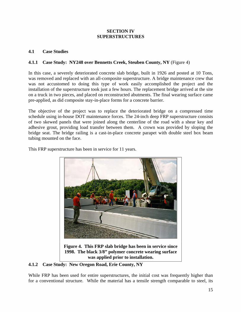
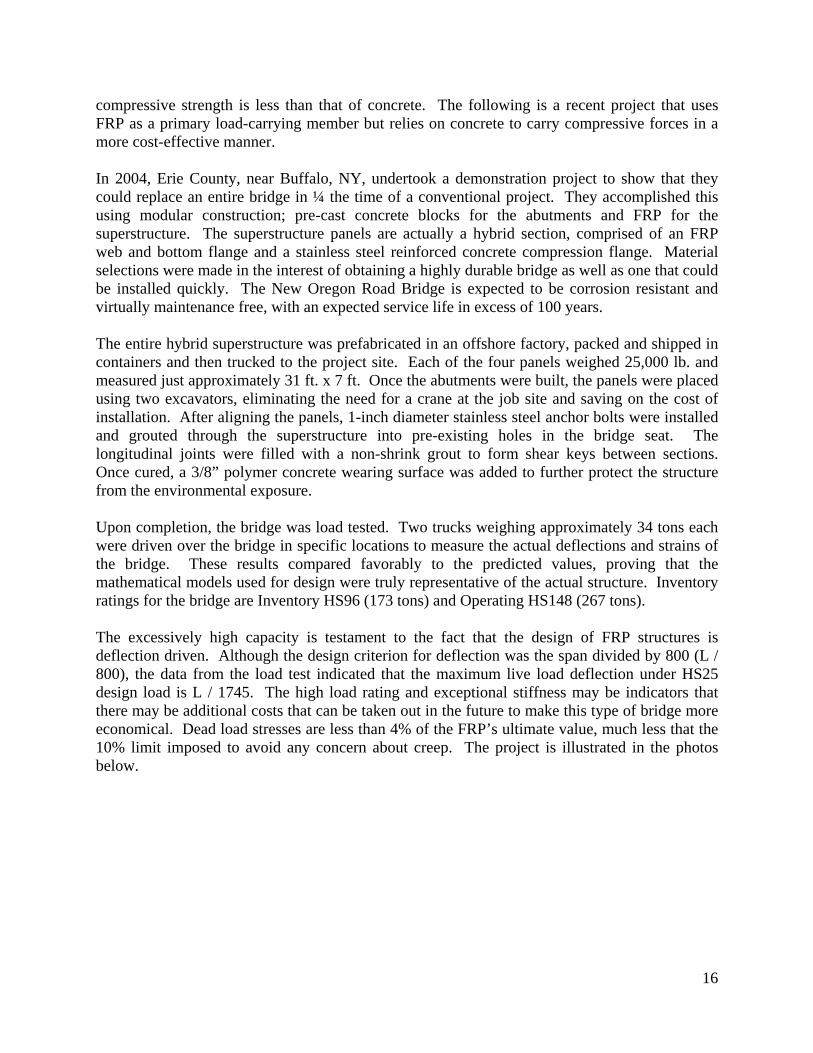
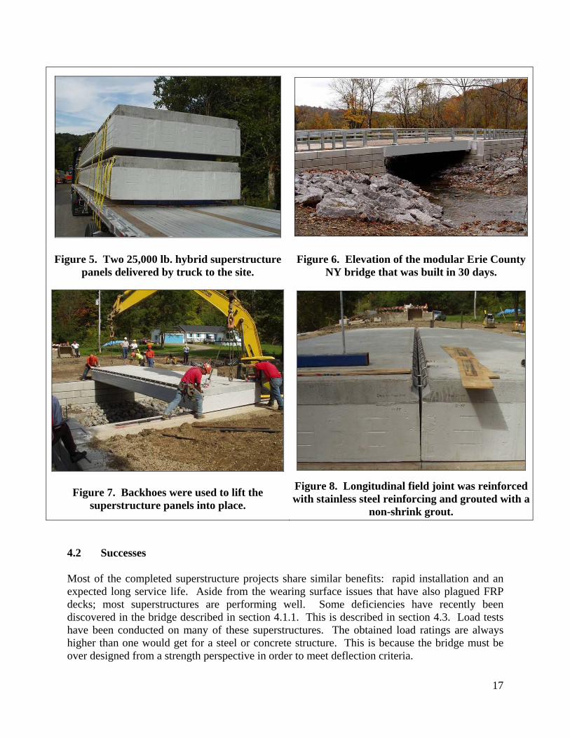
Figure 5. Two 25,000 lb. hybrid superstructure panels delivered by truck to the site.
Figure 6. Elevation of the modular Erie County NY bridge that was built in 30 days.
Figure 7. Backhoes were used to lift the superstructure panels into place.
Figure 8. Longitudinal field joint was reinforced with stainless steel reinforcing and grouted with a
non-shrink grout. 4.2 Successes Most of the completed superstructure projects share similar benefits: rapid installation and an expected long service life. Aside from the wearing surface issues that have also plagued FRP decks; most superstructures are performing well. Some deficiencies have recently been discovered in the bridge described in section 4.1.1. This is described in section 4.3. Load tests have been conducted on many of these superstructures. The obtained load ratings are always higher than one would get for a steel or concrete structure. This is because the bridge must be over designed from a strength perspective in order to meet deflection criteria.
18
4.3 Issues Cost Cost has been the primary hurdle to a wider use of FRP for primary structural members. Although there are frequently other benefits derived from using accelerated bridge construction, the per square foot unit cost initially is typically higher than conventional materials. Because of uncertainties about the future, lower life cycle costs due to low maintenance and a longer life are seldom quantified and considered. Design Design of FRP sections usually required a finite element analysis, which is not standard skill set possessed by design engineers at a typical Department of Transportation or consulting firm. Maintenance A few bridges made with sandwich construction have delaminated after being placed in service. This may have resulted from insufficient QC/QA during fabrication or from a general lack of experience working with these materials. The malfunction in the field has presented a quandary for maintenance personnel because they are not trained to perform repairs for this type of deck, and standard repair guidelines do not exist for FRP, as is the case for conventional materials. Debonding of sandwich sections A few of the structural panels fabricated as a sandwich section using VARTM technology have had structural problems. One of these is the superstructure described in section 4.1.1. Soon after installation, a bridge inspector conducting a tap test discovered a hollow sound on the bottom side. The apparent void was repaired using epoxy injection and the bridge served faithfully for the next 10+ years, with its structural integrity validated intermittently by load testing. These tests were originally intended to monitor performance over time but also served the purpose of demonstrating a satisfactory repair. Every test showed that the bridge had a live load capacity over twice the design load. In 2009, a new problem became apparent in this same bridge. After some investigation, it was determined that the top face-skin had debonded in a large area of the travel lane and the foam core was retaining water. How water intruded into the supposedly sealed core and the closed cell foam is not known. Since the condition is not entirely understood and could become a long term maintenance problem, the state has repaired it and will monitor the condition closely.
19
SECTION V INTERNATIONAL EXPERIENCE
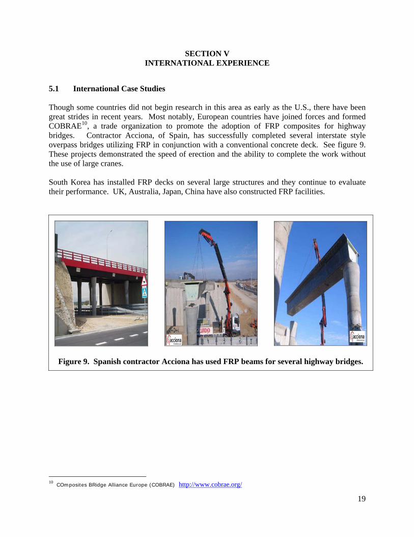
5.1 International Case Studies Though some countries did not begin research in this area as early as the U.S., there have been great strides in recent years. Most notably, European countries have joined forces and formed COBRAE10, a trade organization to promote the adoption of FRP composites for highway bridges. Contractor Acciona, of Spain, has successfully completed several interstate style overpass bridges utilizing FRP in conjunction with a conventional concrete deck. See figure 9. These projects demonstrated the speed of erection and the ability to complete the work without the use of large cranes. South Korea has installed FRP decks on several large structures and they continue to evaluate their performance. UK, Australia, Japan, China have also constructed FRP facilities.
Figure 9. Spanish contractor Acciona has used FRP beams for several highway bridges.
10 COmposites BRidge Alliance Europe (COBRAE) http://www.cobrae.org/
20
SECTION VI FUTURE TRENDS
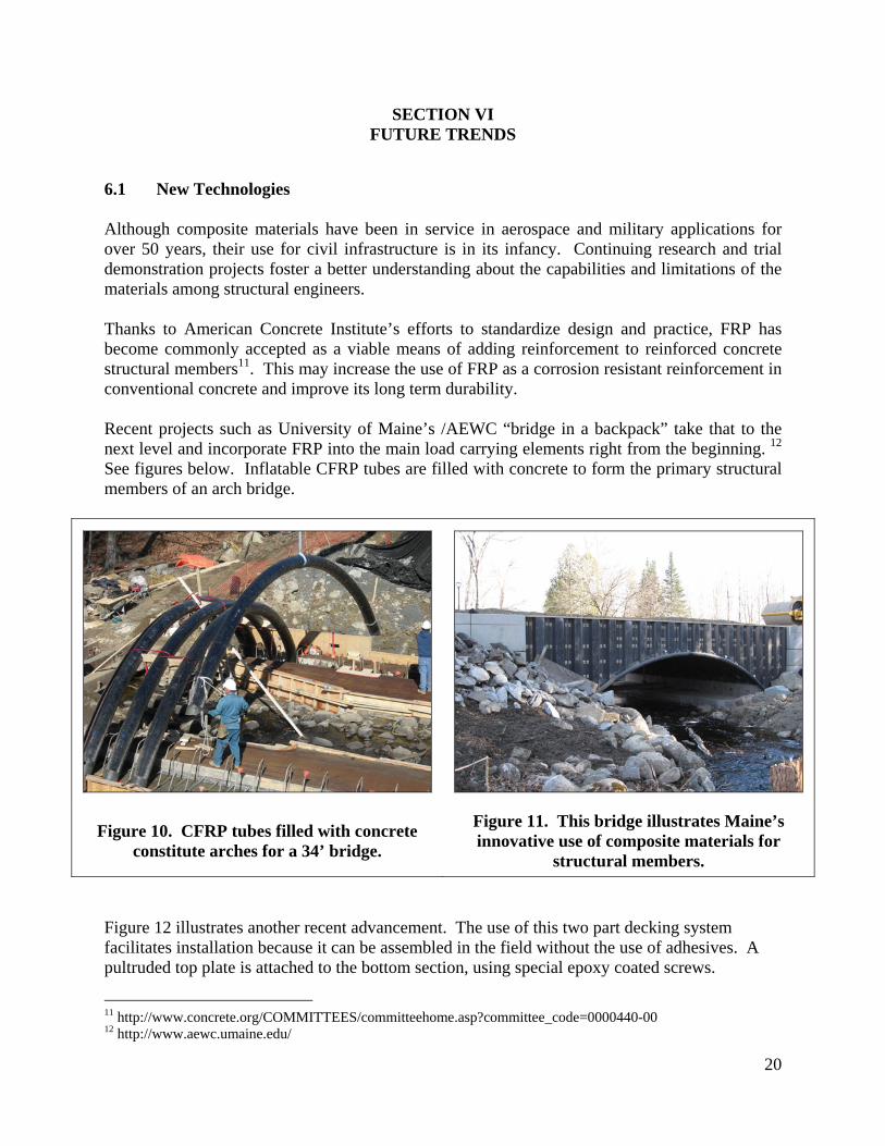
6.1 New Technologies Although composite materials have been in service in aerospace and military applications for over 50 years, their use for civil infrastructure is in its infancy. Continuing research and trial demonstration projects foster a better understanding about the capabilities and limitations of the materials among structural engineers. Thanks to American Concrete Institute’s efforts to standardize design and practice, FRP has become commonly accepted as a viable means of adding reinforcement to reinforced concrete structural members11. This may increase the use of FRP as a corrosion resistant reinforcement in conventional concrete and improve its long term durability. Recent projects such as University of Maine’s /AEWC “bridge in a backpack” take that to the next level and incorporate FRP into the main load carrying elements right from the beginning. 12 See figures below. Inflatable CFRP tubes are filled with concrete to form the primary structural members of an arch bridge.
Figure 10. CFRP tubes filled with concrete constitute arches for a 34’ bridge.
Figure 11. This bridge illustrates Maine’s innovative use of composite materials for
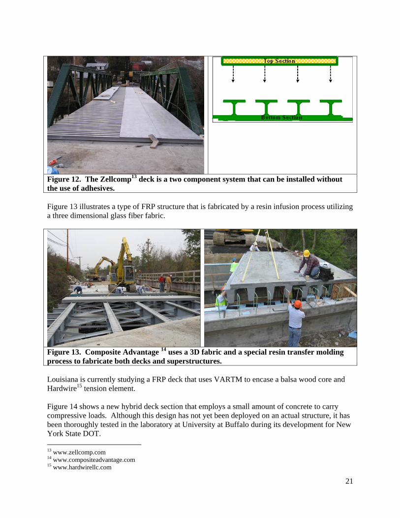
structural members. Figure 12 illustrates another recent advancement. The use of this two part decking system facilitates installation because it can be assembled in the field without the use of adhesives. A pultruded top plate is attached to the bottom section, using special epoxy coated screws.
11 http://www.concrete.org/COMMITTEES/committeehome.asp?committee_code=0000440-00 12 http://www.aewc.umaine.edu/
21
Figure 12. The Zellcomp13 deck is a two component system that can be installed without the use of adhesives. Figure 13 illustrates a type of FRP structure that is fabricated by a resin infusion process utilizing a three dimensional glass fiber fabric.
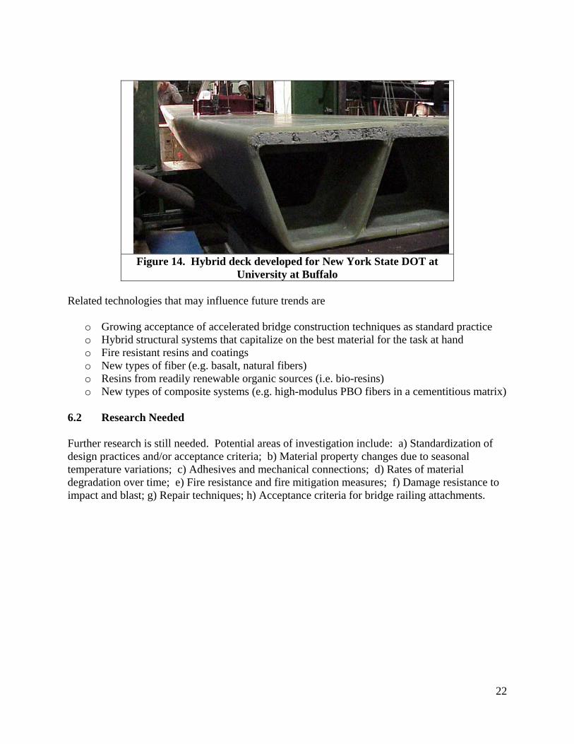
Figure 13. Composite Advantage 14 uses a 3D fabric and a special resin transfer molding process to fabricate both decks and superstructures. Louisiana is currently studying a FRP deck that uses VARTM to encase a balsa wood core and Hardwire15 tension element. Figure 14 shows a new hybrid deck section that employs a small amount of concrete to carry compressive loads. Although this design has not yet been deployed on an actual structure, it has been thoroughly tested in the laboratory at University at Buffalo during its development for New York State DOT. 13 www.zellcomp.com 14 www.compositeadvantage.com 15 www.hardwirellc.com
22
Figure 14. Hybrid deck developed for New York State DOT at
University at Buffalo Related technologies that may influence future trends are
o Growing acceptance of accelerated bridge construction techniques as standard practice o Hybrid structural systems that capitalize on the best material for the task at hand o Fire resistant resins and coatings o New types of fiber (e.g. basalt, natural fibers) o Resins from readily renewable organic sources (i.e. bio-resins) o New types of composite systems (e.g. high-modulus PBO fibers in a cementitious matrix)
6.2 Research Needed Further research is still needed. Potential areas of investigation include: a) Standardization of design practices and/or acceptance criteria; b) Material property changes due to seasonal temperature variations; c) Adhesives and mechanical connections; d) Rates of material degradation over time; e) Fire resistance and fire mitigation measures; f) Damage resistance to impact and blast; g) Repair techniques; h) Acceptance criteria for bridge railing attachments.

23
ACKNOWLEDGEMENTS The authors are members of FHWA’s Virtual Team for FRP Composites. The information presented is possible through the contributions of fellow team members and contributions of project Owners. All statements presented herein are the sole responsibility of the authors and do not represent the views of their employers. The discussion of projects, fabricators, techniques, countries, successes and problems is for the benefit of the reader and the advancement of the technology; it is not intended to endorse or denounce by mention or omission.
24
REFERENCES
1. FHWA FRP Virtual Team , Working copy of “Database of FRP deck and Superstructure Projects in the U.S.”, Sept. 2009
2. “Fiber Reinforced Polymer (FRP) Composite Bridge Technology, Current Practice”, Federal Highway Administration website http://www.fhwa.dot.gov/bridge/frp/frppract.htm
3. Federal Highway Administration, Publication No. FHWA-ERC-2-002, Fiber Reinforced Polymer Composite Bridges of West Virginia, 2001
4. Federal Highway Administration / New York State Department of Transportation, Fiber Reinforced Polymer Bridge Decks of New York, 2003.
5. National Composite Center (NCC), FRP Bridges website http://www.compositecenter.org/infrastr1.php 2004
6. Martin Marietta Composites (MMC) www.martinmarietta.com/Products/bridge_locator.asp
7. Creese, Robert, Gangarao, Hota, Polymer Composites III, Proceedings, 2004 8. NCHRP Project 10-64 Field Inspection of In-service FRP Bridge Decks