Embed Size (px)
Citation preview
Slide 9 - 1 ADS 2009 (version 1.0) Copyright Agilent Technologies 2009
Final Circuit & System Simulation - with Optional
Co-Simulation
Slide 9 - 2 ADS 2009 (version 1.0) Copyright Agilent Technologies 2009
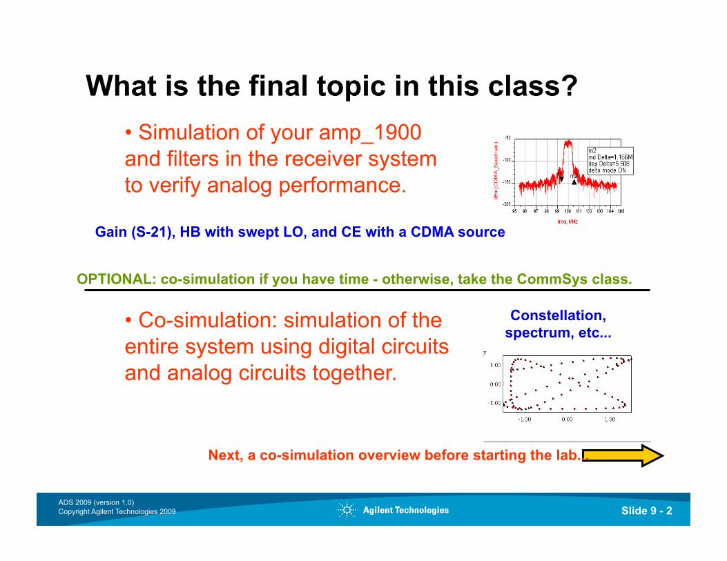
What is the final topic in this class? • Simulation of your amp_1900 and filters in the receiver system to verify analog performance.
• Co-simulation: simulation of the entire system using digital circuits and analog circuits together.
Constellation, spectrum, etc...
Gain (S-21), HB with swept LO, and CE with a CDMA source
Next, a co-simulation overview before starting the lab...
OPTIONAL: co-simulation if you have time - otherwise, take the CommSys class.

Slide 9 - 3 ADS 2009 (version 1.0) Copyright Agilent Technologies 2009
Co-simulation = digital + analog
Agilent Ptolemy is a bridge between the DSP and RF/Analog worlds!
It is your amp_1900 and filters in the receiver system at the bottom level. On the top level is a Data Flow simulation.
Co-simulation is digital & RF/analog circuits simulating together.
This is your rf_system with amp_1900.
What is Ptolemy?

Slide 9 - 4 ADS 2009 (version 1.0) Copyright Agilent Technologies 2009
What is Ptolemy ?
• TSDF is a unique Agilent EEsof Innovation • Agilent Ptolemy adds timed elements - parameters on signals are t, I, Q, Fc (rf carrier)
• Benefits: - easy to add real RF effects on signals - more efficient simulations - more accurate modeling of RF effects
Agilent Ptolemy is a Timed Synchronous Data Flow Simulator

Slide 9 - 5 ADS 2009 (version 1.0) Copyright Agilent Technologies 2009
What is Data Flow?
Tokens can also be “time stamped” - then they become samples. Now you can simulate time and frequency domain impairments such as multi-path and fading ...
arc (or wire)
NODE (or component)
NODE (or component)
Token
Tokens (current or numbers)
How does it all work?
Slide 9 - 6 ADS 2009 (version 1.0) Copyright Agilent Technologies 2009
Bits can flow into A/RF and out!
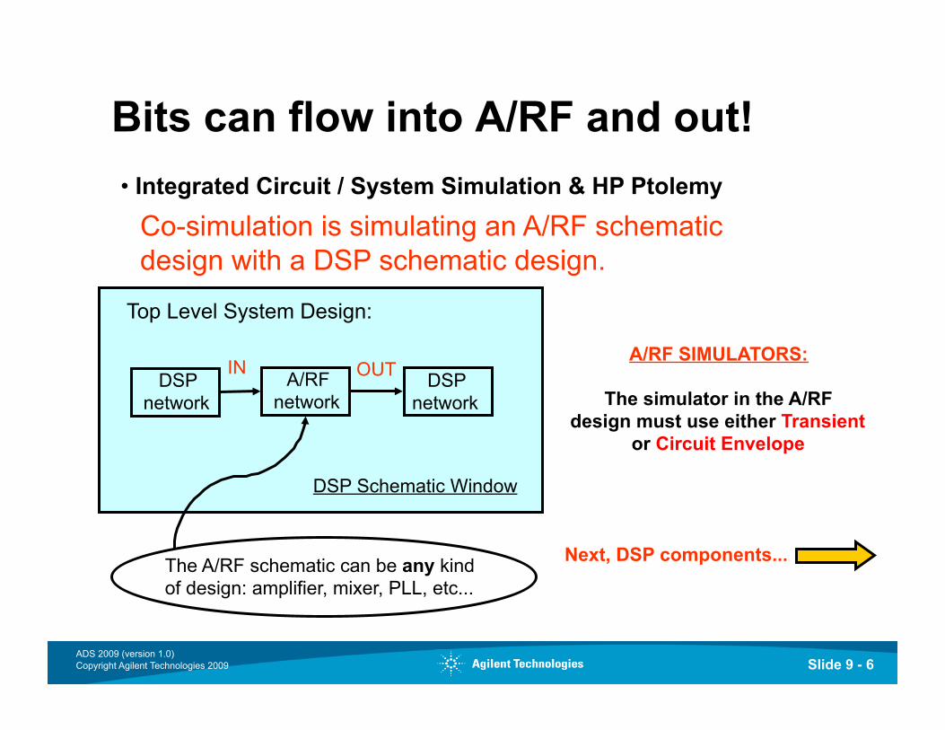
Co-simulation is simulating an A/RF schematic design with a DSP schematic design.
Top Level System Design:
DSP network
A/RF network
DSP network
The A/RF schematic can be any kind of design: amplifier, mixer, PLL, etc...
The simulator in the A/RF design must use either Transient
or Circuit Envelope
DSP Schematic Window
IN OUT A/RF SIMULATORS:
Next, DSP components...

Slide 9 - 7 ADS 2009 (version 1.0) Copyright Agilent Technologies 2009
The DSP components library… Many palette selections and additional libraries:
The use of these tools is covered in the DSP course and also in part of the CommSys course. 3GPP and WLAN courses are also available. In this class, DSP is only briefly introduced!
LAB
Slide 9 - 8 ADS 2009 (version 1.0) Copyright Agilent Technologies 2009
Lab 9:
Final System Simulation with amp_1900 and filters

Slide 9 - 9 ADS 2009 (version 1.0) Copyright Agilent Technologies 2009
Steps in the Design Process • Design the RF sys behavioral model receiver • Test conversion gain, spectrum, etc. • Start amp_1900 design – subckt parasitics • Simulate amp DC conditions & bias network • Simulate amp AC response - verify gain • Test amp noise contributions – tune parameters • Simulate amp S-parameter response • Create a matching topology • Optimize the amp in & out matching networks • Filter design – lumped 200MHz LPF • Filter design – microstrip 1900 MHz BPF • Transient and Momentum filter analysis • Amp spectrum, delivered power, Zin - HB • Test amp comp, distortion, two-tone, TOI • CE basics for spectrum and baseband • CE for amp_1900 with GSM source • Replace amp and filters in rf_sys receiver • Test conversion gain, NF, swept LO power • Final CDMA system test CE with fancy DDS • Co-simulation of behavioral system
You are here:

Slide 9 - 10 ADS 2009 (version 1.0) Copyright Agilent Technologies 2009
First, set up the sub-circuits & system Use port connectors and the File > Design Parameters
Later on, replace the behavioral models with the circuits you built.
Slide 9 - 11 ADS 2009 (version 1.0) Copyright Agilent Technologies 2009
1
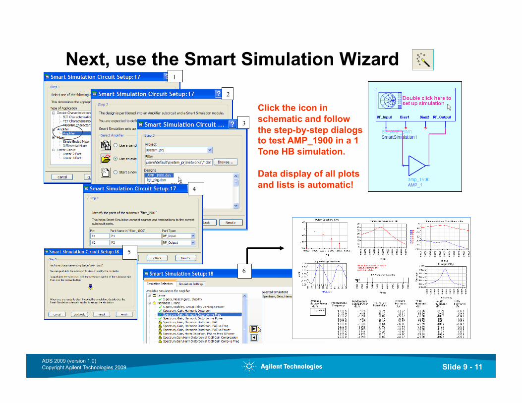
Next, use the Smart Simulation Wizard
Click the icon in schematic and follow the step-by-step dialogs to test AMP_1900 in a 1 Tone HB simulation.
Data display of all plots and lists is automatic!
2
3
4
5
6

Slide 9 - 12 ADS 2009 (version 1.0) Copyright Agilent Technologies 2009
Next, set up and run HB with swept LO power
Plot: dBm_out vs LO_pwr. Write and list the IF_gain.
NF and conversion gain appear if status level = 4.
Final simulation...
Turn on Display
Slide 9 - 13 ADS 2009 (version 1.0) Copyright Agilent Technologies 2009
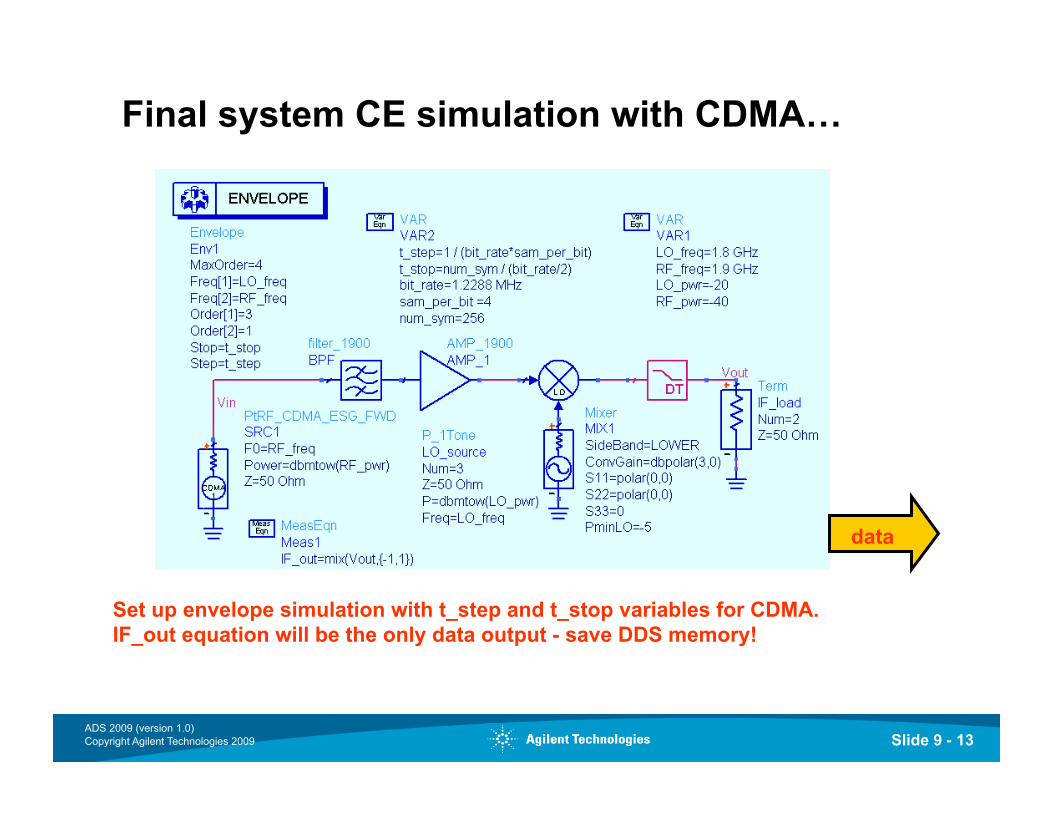
Final system CE simulation with CDMA…
data
Set up envelope simulation with t_step and t_stop variables for CDMA. IF_out equation will be the only data output - save DDS memory!
Slide 9 - 14 ADS 2009 (version 1.0) Copyright Agilent Technologies 2009
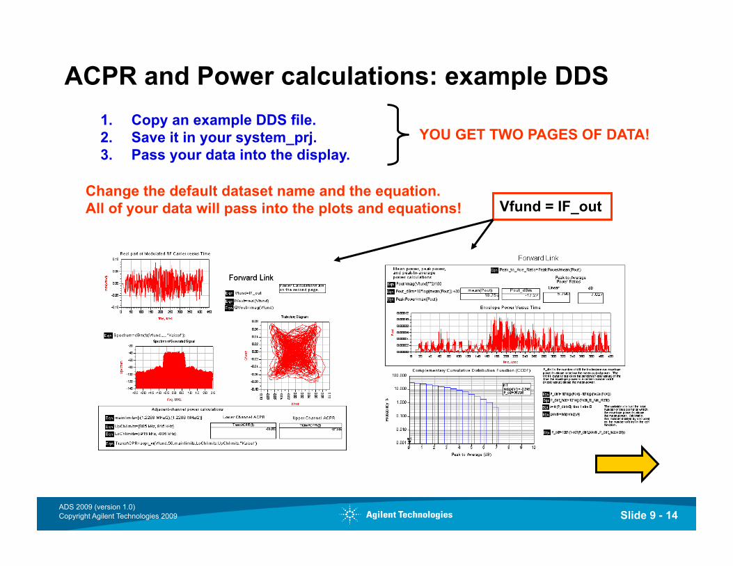
ACPR and Power calculations: example DDS
Change the default dataset name and the equation. All of your data will pass into the plots and equations!
1. Copy an example DDS file. 2. Save it in your system_prj. 3. Pass your data into the display.
Vfund = IF_out
YOU GET TWO PAGES OF DATA!
Slide 9 - 15 ADS 2009 (version 1.0) Copyright Agilent Technologies 2009
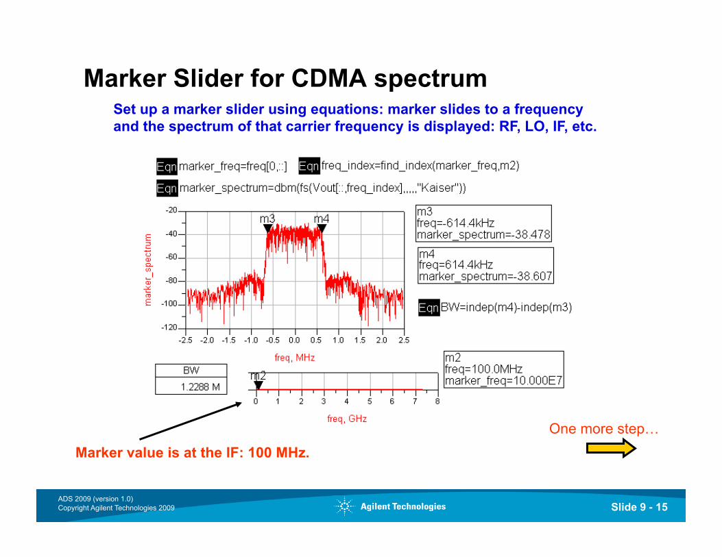
Marker Slider for CDMA spectrum Set up a marker slider using equations: marker slides to a frequency and the spectrum of that carrier frequency is displayed: RF, LO, IF, etc.
Marker value is at the IF: 100 MHz. One more step…
Slide 9 - 16 ADS 2009 (version 1.0) Copyright Agilent Technologies 2009
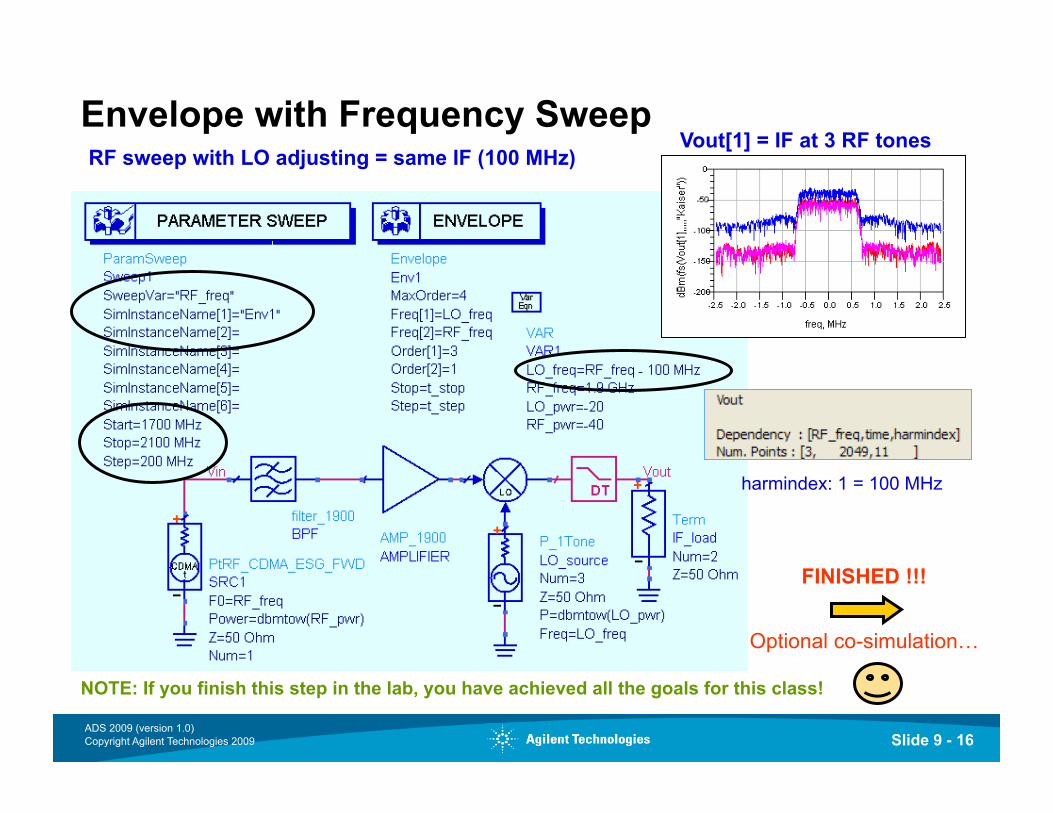
Envelope with Frequency Sweep
FINISHED !!!
Optional co-simulation…
RF sweep with LO adjusting = same IF (100 MHz)
NOTE: If you finish this step in the lab, you have achieved all the goals for this class!
Vout[1] = IF at 3 RF tones
harmindex: 1 = 100 MHz
Slide 9 - 17 ADS 2009 (version 1.0) Copyright Agilent Technologies 2009
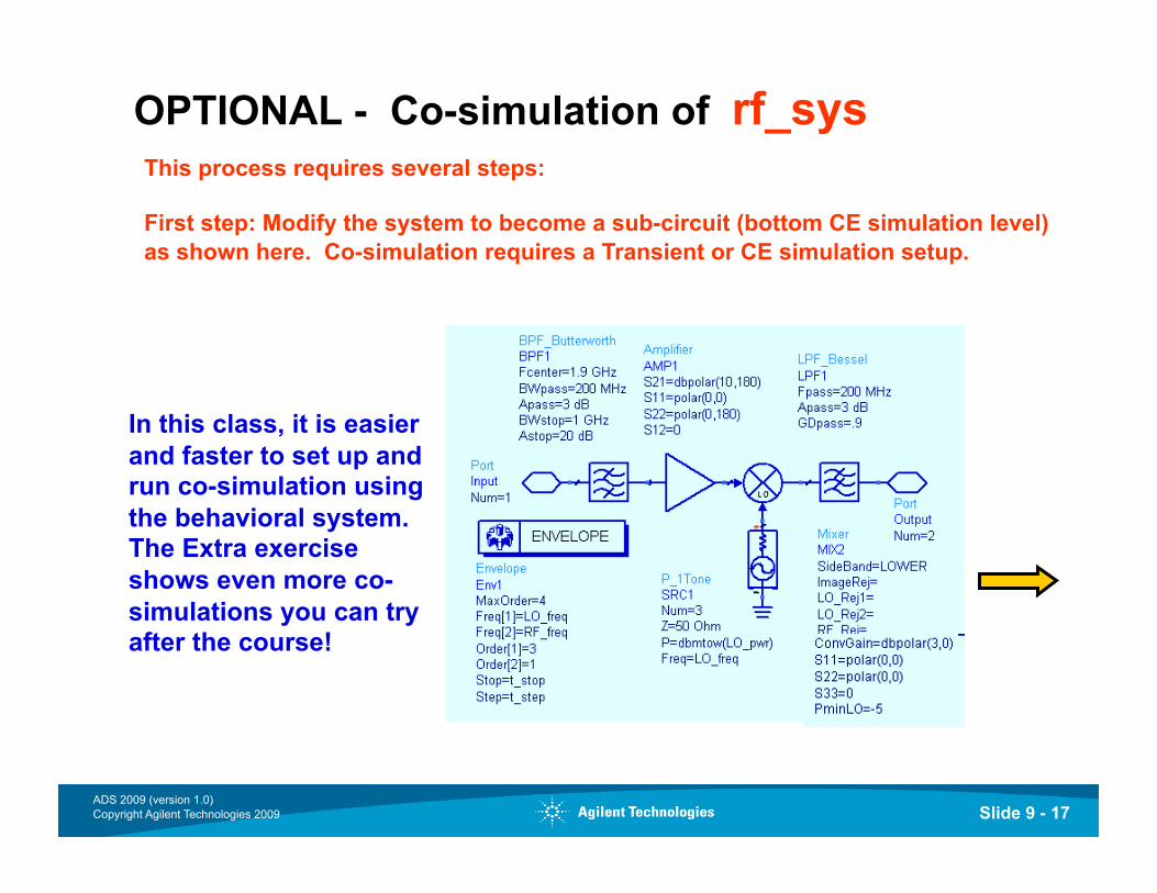
OPTIONAL - Co-simulation of rf_sys This process requires several steps:
First step: Modify the system to become a sub-circuit (bottom CE simulation level) as shown here. Co-simulation requires a Transient or CE simulation setup.
In this class, it is easier and faster to set up and run co-simulation using the behavioral system. The Extra exercise shows even more co-simulations you can try after the course!
Slide 9 - 18 ADS 2009 (version 1.0) Copyright Agilent Technologies 2009
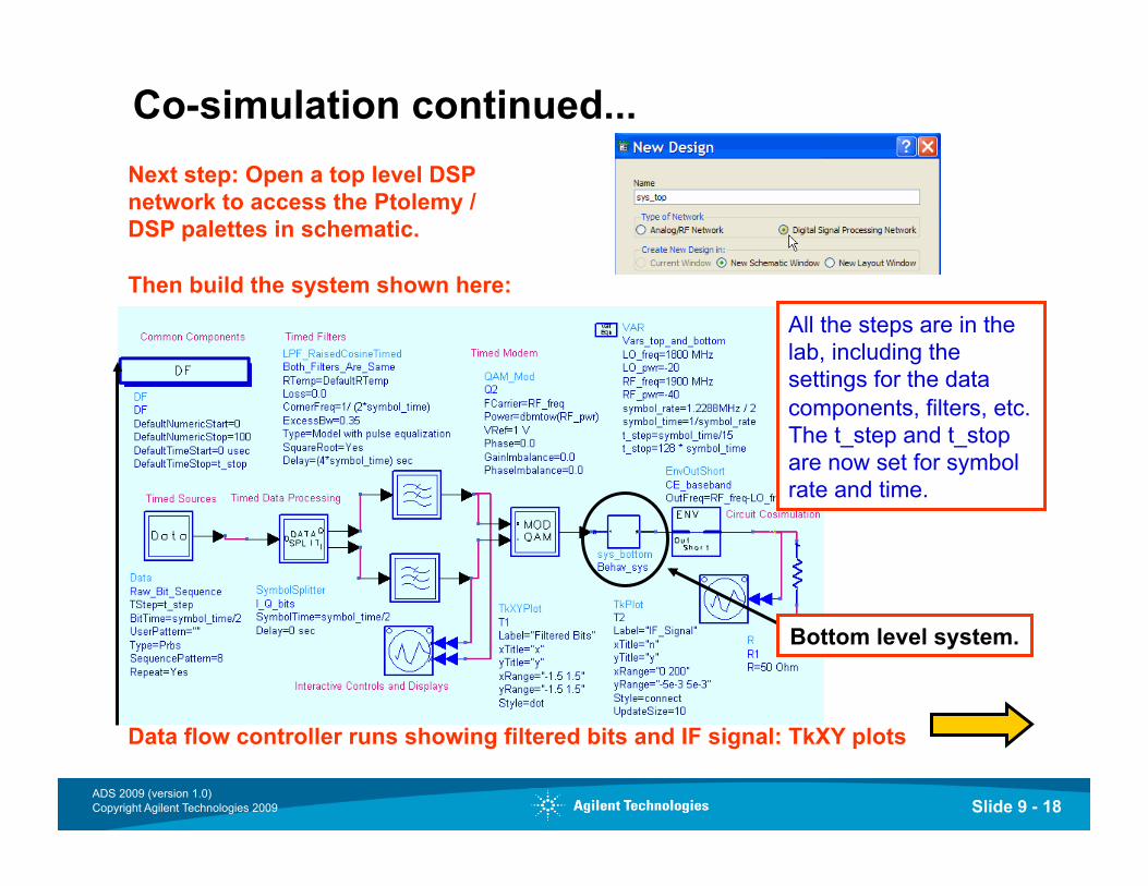
Co-simulation continued... Next step: Open a top level DSP network to access the Ptolemy / DSP palettes in schematic.
Then build the system shown here: All the steps are in the lab, including the settings for the data components, filters, etc. The t_step and t_stop are now set for symbol rate and time.
Bottom level system.
Data flow controller runs showing filtered bits and IF signal: TkXY plots

Slide 9 - 19 ADS 2009 (version 1.0) Copyright Agilent Technologies 2009
Data Flow simulation - TK plots are active!
Quit the DF simulation and connect a SpectrumAnalyzer sink to collect the data. Results of this co-simulation show spectrum of the behavioral system. To use amp_1900 and your filters, replace them in the system and setup a new simulation (requires more time).
Spectrum Analyzer sink:
Start the lab now!

Slide 9 - 20 ADS 2009 (version 1.0) Copyright Agilent Technologies 2009
End of the Course
Goodbye and see you next time! www.agilent.com
Agilent EEsof EDA - Customer Education


![sharing-economy.jp...¬ª»¾®¯Àµ² e S ¤¡ ¤ O j ¸½5 j Vm ¤9A ¯Àµ² I; ¤ = £0 ¤ ¬ª»¾®¯Àµ² X ~'( 9A¿¯Àµ² Vm ] ¤ Vm ¤9A L ¡ ¤ E` Vm ¤9A L 5 '( Vm 9A¿¯Àµ²](https://img.pdfslide.us/doc/110x75/5f067c9d7e708231d4183c06/sharing-e-s-o-j-5-j-vm-9a-i-.jpg)
![Title 9A RCW - Washingtonleg.wa.gov/CodeReviser/RCWSelectedTitles/Documents/2016/9A.pdf · 9A.04.040 Title 9A RCW: Washington Criminal Code [Title 9A RCW—page 2] (2016 Ed.) (3)](https://img.pdfslide.us/doc/110x75/5f10764b7e708231d4493a23/title-9a-rcw-9a04040-title-9a-rcw-washington-criminal-code-title-9a-rcwapage.jpg)