Embed Size (px)
DESCRIPTION
Blasting Demolition in Southern California's Hollywood Park
Citation preview
COMMERCIAL IN CONFIDENCE. 19 May 2015
! EXPLOSIVE DEMOLITION SPECIALIST
BLAST PLAN, CONCEPT & PROTECTIVE MEASURES
Felling the Steel Column Cantilever Roof Hollywood Park, California
National Demolition Contractors 1536 W. 25th Street #248
San Pedro, CA 90732 (310) 732-1991 Office (310) 832-4989 Fax
www.nationaldemolition.com DYKON EXPLOSIVE DEMOLITION Corp., Tulsa, OK O: 918 583 9566 Jim Mobile: 918 740 3425 ! of !1 20
Hollywood ParkCantilever Roof
COMMERCIAL IN CONFIDENCE. 19 May 2015
! EXPLOSIVE DEMOLITION CORP.
INTRODUCTION
NATIONAL DEMOLITION CONTRACTORS 1536 W. 25th Street #248, San Pedro, CA 90732 have been contracted to perform demolition and removal operations at the Cantilever Roof, Hollywood, CA. This structure is considered a good candidate for an explosive demolition application due to its construction design, height to mass ratio, and proximity to adjacent structures. NATIONAL DEMOLITION CONTRACTORS ensures the competent person survey, other related, required documentation and all permits are kept current.
DYKON of Tulsa, OK has been contacted by NATIONAL DEMOLITION CONTRACTORS to provide feasibility and cost analysis relative to the site requirements for demolition work using explosive methods. DYKON Explosive Demolition Corp. founded in 1975 has successfully brought down many structures throughout the United States and abroad. DYKON’S range of services include controlled building implosions, chimneys, bridges, piers, industrial structures, reinforced mass concrete, rock blasting, and all phases of explosive technology.
DYKON is confident in addressing and proposing explosive demolition as a viable means to meet the requirements of this project. This method will reduce the time to remove the stated structure, and ultimately provide a safer alternative to conventional methods. The use of explosive technology to bring down structures has been well documented as a proven alternative, even in highly sensitive areas. The implosion method has evolved into an acceptable and successful standard of practice worldwide for over three decades. ALL attached supportive documentation, for safe explosive felling philosophies of approach, are to Demolition Industry Best Practices.
EXPLOSIVE DEMOLITION WORK PLAN Description of Site and Structure for Explosive Felling Preparation
The Cantilever Roof Structure lends itself well to be demolished by explosive felling. The demolition of the surrounding structures are on-going with preparations for explosive felling continuing. Note all the attached DYKON CONCEPT Drawings for reference.The basic Structure Preparations are detailed in the BASIC PREPARATIONS LIST. DYKON’S Felling Concept is a living document (subject to additional site inspection amendments and alternative revision concepts) for Engineering approvals as necessary and final blast plan implementation. Explosive felling event to follow.
Note attached: 01_DYKON FELLING CONCEPT / BLAST AREA
BLUE indicated areas are to be prepared, marked and torch cut for stiff side, supporting the structure during explosive felling. This stiff side support allows the structure to remain secure, prevent structure from “squatting”, prevent columns from kicking back and allowing for tipping the structure towards the desired felling direction. BLUE indicated columns are Double “V” cut, anchor bolts cut at Grade or Splice Plates cut on upper elevations to facilitate structure rotation towards desired felling direction.
RED indicated steel columns are to be prepared, marked and torch cut for explosive charge placement and subsequent protective measures applied. The RED columns are the only columns to have explosive charges applied at Ground elevation. All the RED
DYKON EXPLOSIVE DEMOLITION Corp., Tulsa, OK O: 918 583 9566 Jim Mobile: 918 740 3425 ! of !2 20
COMMERCIAL IN CONFIDENCE. 19 May 2015
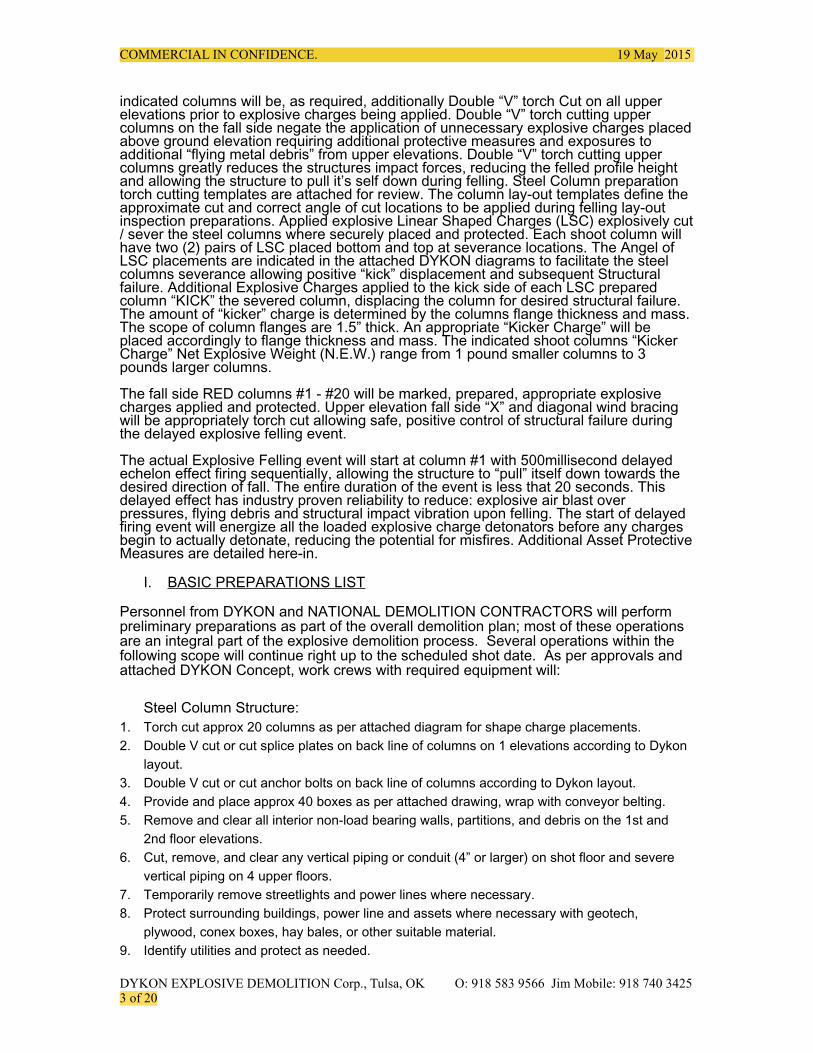
indicated columns will be, as required, additionally Double “V” torch Cut on all upper elevations prior to explosive charges being applied. Double “V” torch cutting upper columns on the fall side negate the application of unnecessary explosive charges placed above ground elevation requiring additional protective measures and exposures to additional “flying metal debris” from upper elevations. Double “V” torch cutting upper columns greatly reduces the structures impact forces, reducing the felled profile height and allowing the structure to pull it’s self down during felling. Steel Column preparation torch cutting templates are attached for review. The column lay-out templates define the approximate cut and correct angle of cut locations to be applied during felling lay-out inspection preparations. Applied explosive Linear Shaped Charges (LSC) explosively cut / sever the steel columns where securely placed and protected. Each shoot column will have two (2) pairs of LSC placed bottom and top at severance locations. The Angel of LSC placements are indicated in the attached DYKON diagrams to facilitate the steel columns severance allowing positive “kick” displacement and subsequent Structural failure. Additional Explosive Charges applied to the kick side of each LSC prepared column “KICK” the severed column, displacing the column for desired structural failure. The amount of “kicker” charge is determined by the columns flange thickness and mass. The scope of column flanges are 1.5” thick. An appropriate “Kicker Charge” will be placed accordingly to flange thickness and mass. The indicated shoot columns “Kicker Charge” Net Explosive Weight (N.E.W.) range from 1 pound smaller columns to 3 pounds larger columns.
The fall side RED columns #1 - #20 will be marked, prepared, appropriate explosive charges applied and protected. Upper elevation fall side “X” and diagonal wind bracing will be appropriately torch cut allowing safe, positive control of structural failure during the delayed explosive felling event.
The actual Explosive Felling event will start at column #1 with 500millisecond delayed echelon effect firing sequentially, allowing the structure to “pull” itself down towards the desired direction of fall. The entire duration of the event is less that 20 seconds. This delayed effect has industry proven reliability to reduce: explosive air blast over pressures, flying debris and structural impact vibration upon felling. The start of delayed firing event will energize all the loaded explosive charge detonators before any charges begin to actually detonate, reducing the potential for misfires. Additional Asset Protective Measures are detailed here-in.
I. BASIC PREPARATIONS LIST
Personnel from DYKON and NATIONAL DEMOLITION CONTRACTORS will perform preliminary preparations as part of the overall demolition plan; most of these operations are an integral part of the explosive demolition process. Several operations within the following scope will continue right up to the scheduled shot date. As per approvals and attached DYKON Concept, work crews with required equipment will:
Steel Column Structure: 1. Torch cut approx 20 columns as per attached diagram for shape charge placements. 2. Double V cut or cut splice plates on back line of columns on 1 elevations according to Dykon
layout. 3. Double V cut or cut anchor bolts on back line of columns according to Dykon layout. 4. Provide and place approx 40 boxes as per attached drawing, wrap with conveyor belting. 5. Remove and clear all interior non-load bearing walls, partitions, and debris on the 1st and
2nd floor elevations. 6. Cut, remove, and clear any vertical piping or conduit (4” or larger) on shot floor and severe
vertical piping on 4 upper floors. 7. Temporarily remove streetlights and power lines where necessary. 8. Protect surrounding buildings, power line and assets where necessary with geotech,
plywood, conex boxes, hay bales, or other suitable material. 9. Identify utilities and protect as needed.
DYKON EXPLOSIVE DEMOLITION Corp., Tulsa, OK O: 918 583 9566 Jim Mobile: 918 740 3425 ! of !3 20
COMMERCIAL IN CONFIDENCE. 19 May 2015
I. SAFETY
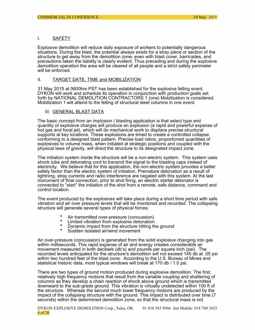
Explosive demolition will reduce daily exposure of workers to potentially dangerous situations. During the blast, the potential always exists for a stray piece or section of the structure to get away from the demolition zone; even with blast cover, barricades, and precautions taken the liability is clearly evident. Thus preceding and during the explosive demolition operation the area will be cleared of all people and a strict safety perimeter will be enforced.
II. TARGET DATE, TIME and MOBILIZATION
31 May 2015 at 0600hrs PST has been established for the explosive felling event. DYKON will work and schedule its operation in conjunction with production goals set forth by NATIONAL DEMOLITION CONTRACTORS 1 (one) Mobilization is considered. Mobilization 1 will attend to the felling of structural steel columns in one event.
III. GENERAL BLAST DATA
The basic concept from an implosion / blasting application is that select type and quantity of explosive charges will produce an explosion (a rapid and powerful expanse of hot gas and focal jet), which will do mechanical work to displace precise structural supports at key locations. These explosions are timed to create a controlled collapse conforming to a designed blast pattern. Precise load ratios, proportioned quantities of explosives to volume mass, when initiated at strategic positions and coupled with the physical laws of gravity, will direct the structure to its designated impact zone.
The initiation system inside the structure will be a non-electric system. This system uses shock tube and detonating cord to transmit the signal to the blasting caps instead of electricity. We believe that for this application, the non-electric system provides a better safety factor than the electric system of initiation. Premature detonation as a result of lightning, stray currents and radio interference are negated with this system. At the last monument of final connection, prior to shot firing, an electric starter detonator is connected to “start” the initiation of the shot from a remote, safe distance, command and control location.
The event produced by the explosives will take place during a short time period with safe vibration and air over pressure levels that will be monitored and recorded. The collapsing structure will generate several types of physical forces:
• Air transmitted over-pressure (concussion) • Limited vibration from explosive detonation • Dynamic impact from the structure hitting the ground • Sudden isolated air/wind movement
Air over-pressure (concussion) is generated from the solid explosive changing into gas within milliseconds. This rapid expanse of air and energy creates considerable air movement measured in both decibels (db’s) and pounds per square inch (psi). The recorded levels anticipated for the structure’s demolition will not exceed 145 db at .05 psi within two hundred feet of the blast zone. According to the U.S. Bureau of Mines and statistical historic data, most typical windows will break at 170 db / 1.0 psi.
There are two types of ground motion produced during explosive demolition. The first, relatively high frequency motions that result from the variable coupling and shattering of columns as they develop a chain reaction of shock above ground which is transmitted downward to the sub-grade ground. This vibration is virtually undetected within 100 ft of the structure. Whereas the second much lower frequency motions are produced by the impact of the collapsing structure with the ground. This impact is distributed over time (7 seconds) within the determined demolition zone, so that the structural mass is not
DYKON EXPLOSIVE DEMOLITION Corp., Tulsa, OK O: 918 583 9566 Jim Mobile: 918 740 3425 ! of !4 20
COMMERCIAL IN CONFIDENCE. 19 May 2015
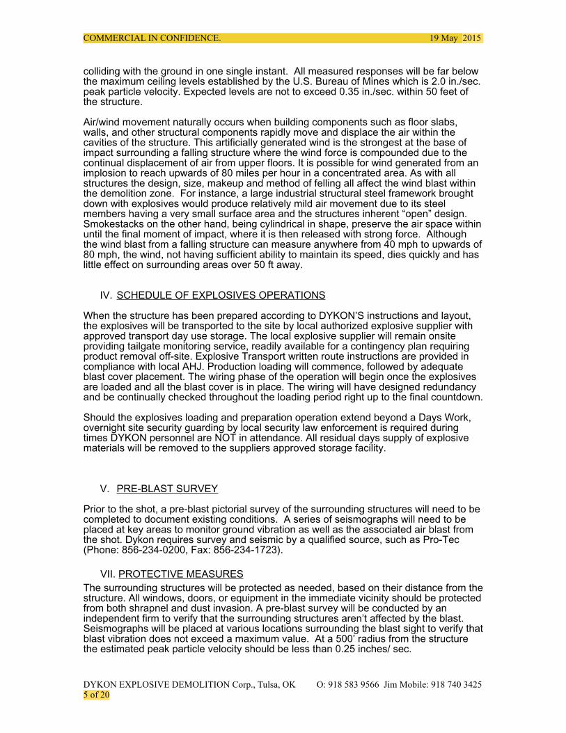
colliding with the ground in one single instant. All measured responses will be far below the maximum ceiling levels established by the U.S. Bureau of Mines which is 2.0 in./sec. peak particle velocity. Expected levels are not to exceed 0.35 in./sec. within 50 feet of the structure.
Air/wind movement naturally occurs when building components such as floor slabs, walls, and other structural components rapidly move and displace the air within the cavities of the structure. This artificially generated wind is the strongest at the base of impact surrounding a falling structure where the wind force is compounded due to the continual displacement of air from upper floors. It is possible for wind generated from an implosion to reach upwards of 80 miles per hour in a concentrated area. As with all structures the design, size, makeup and method of felling all affect the wind blast within the demolition zone. For instance, a large industrial structural steel framework brought down with explosives would produce relatively mild air movement due to its steel members having a very small surface area and the structures inherent “open” design. Smokestacks on the other hand, being cylindrical in shape, preserve the air space within until the final moment of impact, where it is then released with strong force. Although the wind blast from a falling structure can measure anywhere from 40 mph to upwards of 80 mph, the wind, not having sufficient ability to maintain its speed, dies quickly and has little effect on surrounding areas over 50 ft away.
IV. SCHEDULE OF EXPLOSIVES OPERATIONS
When the structure has been prepared according to DYKON’S instructions and layout, the explosives will be transported to the site by local authorized explosive supplier with approved transport day use storage. The local explosive supplier will remain onsite providing tailgate monitoring service, readily available for a contingency plan requiring product removal off-site. Explosive Transport written route instructions are provided in compliance with local AHJ. Production loading will commence, followed by adequate blast cover placement. The wiring phase of the operation will begin once the explosives are loaded and all the blast cover is in place. The wiring will have designed redundancy and be continually checked throughout the loading period right up to the final countdown.
Should the explosives loading and preparation operation extend beyond a Days Work, overnight site security guarding by local security law enforcement is required during times DYKON personnel are NOT in attendance. All residual days supply of explosive materials will be removed to the suppliers approved storage facility.
V. PRE-BLAST SURVEY
Prior to the shot, a pre-blast pictorial survey of the surrounding structures will need to be completed to document existing conditions. A series of seismographs will need to be placed at key areas to monitor ground vibration as well as the associated air blast from the shot. Dykon requires survey and seismic by a qualified source, such as Pro-Tec (Phone: 856-234-0200, Fax: 856-234-1723).
VII. PROTECTIVE MEASURES The surrounding structures will be protected as needed, based on their distance from the structure. All windows, doors, or equipment in the immediate vicinity should be protected from both shrapnel and dust invasion. A pre-blast survey will be conducted by an independent firm to verify that the surrounding structures aren’t affected by the blast. Seismographs will be placed at various locations surrounding the blast sight to verify that blast vibration does not exceed a maximum value. At a 500’ radius from the structure the estimated peak particle velocity should be less than 0.25 inches/ sec.
DYKON EXPLOSIVE DEMOLITION Corp., Tulsa, OK O: 918 583 9566 Jim Mobile: 918 740 3425 ! of !5 20
COMMERCIAL IN CONFIDENCE. 19 May 2015
Casino, Asset Protection will include and not be limited to the following:
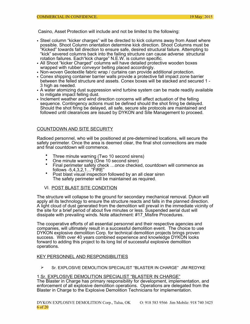
• Steel column “kicker charges” will be directed to kick columns away from Asset where possible. Shoot Column orientation determine kick direction. Shoot Columns must be “Kicked” towards fall direction to ensure safe, desired structural failure. Attempting to “kick” severed columns back into the failing structure can cause adverse structural rotation failures. Each“kick charge” N.E.W. is column specific.
• All Shoot “kicker Charged” columns will have detailed protective wooden boxes wrapped with rubber conveyor belting placed accordingly.
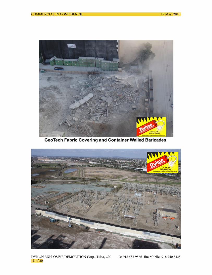
• Non-woven Geotextile fabric wrap / curtains can provide additional protection. • Conex shipping container barrier walls provide a protective fall impact zone barrier
between the felled structure and assets. Conex boxes will be stacked and secured 1 - 3 high as needed.
• A water atomizing dust suppression wind turbine system can be made readily available to mitigate impact felling dust.
• Inclement weather and wind direction concerns will affect actuation of the felling sequence. Contingency actions must be defined should the shot firing be delayed. Should the shot firing be delayed, all safe, secure site protocols are maintained and followed until clearances are issued by DYKON and Site Management to proceed.
COUNTDOWN AND SITE SECURITY
Radioed personnel, who will be positioned at pre-determined locations, will secure the safety perimeter. Once the area is deemed clear, the final shot connections are made and final countdown will commence.
• Three minute warning (Two 10 second sirens) • One minute warning (One 10 second siren) • Final perimeter safety check …once checked, countdown will commence as
follows -5,4,3,2,1…”FIRE” • Post blast visual inspection followed by an all clear siren The safety perimeter will be maintained as required.
VI. POST BLAST SITE CONDITION
The structure will collapse to the ground for secondary mechanical removal. Dykon will apply all its technology to ensure the structure reacts and falls in the planned direction. A light cloud of dust generated from the demolition will prevail in the immediate vicinity of the site for a brief period of about five minutes or less. Suspended aerial dust will dissipate with prevailing winds. Note attachment: #17_Misfire Procedures.
The cooperative efforts of all essential personnel and their respective agencies and companies, will ultimately result in a successful demolition event. The choice to use DYKON explosive demolition Corp. for technical demolition projects brings proven success. With over 40 years combined experience and knowledge DYKON looks forward to adding this project to its long list of successful explosive demolition operations.
KEY PERSONNEL AND RESPONSIBILITIES
! Sr. EXPLOSIVE DEMOLITION SPECIALIST “BLASTER IN CHARGE” JIM REDYKE
1.Sr. EXPLOSIVE DEMOLITION SPECIALIST “BLASTER IN CHARGE” The Blaster in Charge has primary responsibility for development, implementation, and enforcement of all explosive demolition operations. Operations are delegated from the Blaster in Charge to the Explosive Demolition Technicians for implementation.
DYKON EXPLOSIVE DEMOLITION Corp., Tulsa, OK O: 918 583 9566 Jim Mobile: 918 740 3425 ! of !6 20
COMMERCIAL IN CONFIDENCE. 19 May 2015
Responsibilities of the Blaster in Charge include: o Blast design/engineering and logistics o Enforcement of safe explosive handling, usage, transportation and storage o Overseeing the safe loading and wiring of explosives o Directing necessary structural preparations o Involvement in pre-blast meetings with local officials o Securing the blasting zone and controlling all activities within the blast site o Inspection of the post blast site for potential hazards
2.EXPLOSIVE DEMOLITION Technicians
The Explosive Demolition Technicians are responsible for assisting the Blaster in Charge with the implementation of the Health and Safety Work Plan and all explosive demolition activities. The Explosive Demolition Technicians have the authority to direct contractors in their preparations and can suspend work activity if safe practices are not followed.
FELLING CONCEPT INFORMATION: (NOTE ALL Corresponding ATTACHMENTS)
1 Felling Concept. 2 Blast Area.
3 Recommended Exclusion Zone. 4 Type of Explosives used: Detonators. Shaped Charge. Kicker Charge. 5 Quantity of Explosives Used for Column Kicker Charges. 6 Protective Measure Concepts. Column Preparation, Matting Charges. 7 Vibration 8 Airborne Particles 9 MisFire Procedures 10 Insurance Certificates & Blasters License 11 Assorted Photo Examples from previous events.
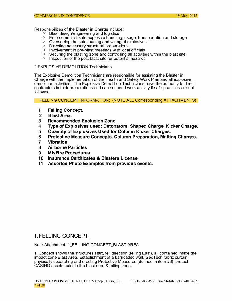
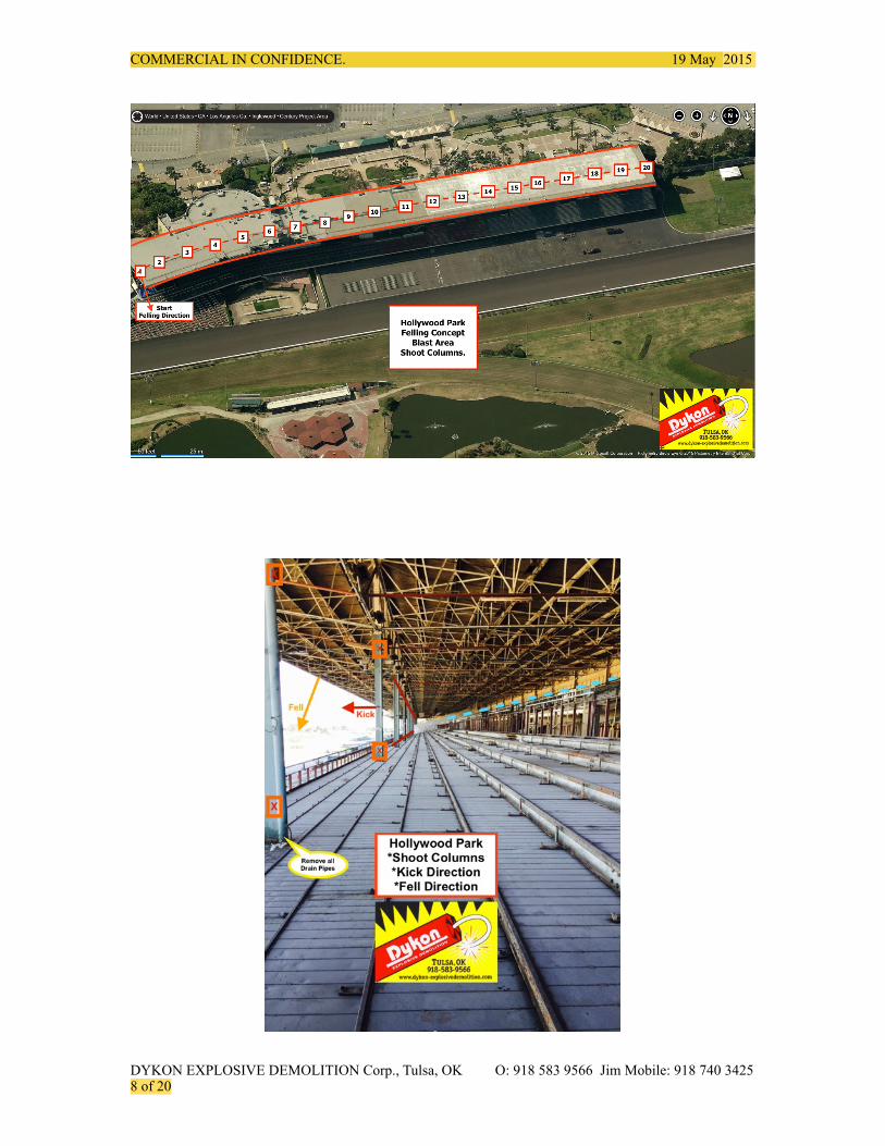
1.FELLING CONCEPT Note Attachment: 1_FELLING CONCEPT_BLAST AREA
1_Concept shows the structures start, fell direction (felling East), all contained inside the impact zone Blast Area. Establishment of a barricaded wall, GeoTech fabric curtain, physically separating and erecting Protective Measures (defined in item #6), protect CASINO assets outside the blast area & felling zone.
DYKON EXPLOSIVE DEMOLITION Corp., Tulsa, OK O: 918 583 9566 Jim Mobile: 918 740 3425 ! of !7 20
COMMERCIAL IN CONFIDENCE. 19 May 2015
DYKON EXPLOSIVE DEMOLITION Corp., Tulsa, OK O: 918 583 9566 Jim Mobile: 918 740 3425 ! of !8 20
COMMERCIAL IN CONFIDENCE. 19 May 2015
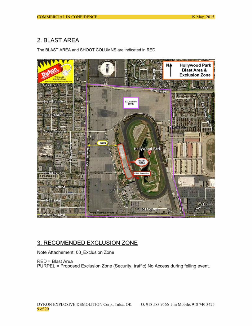
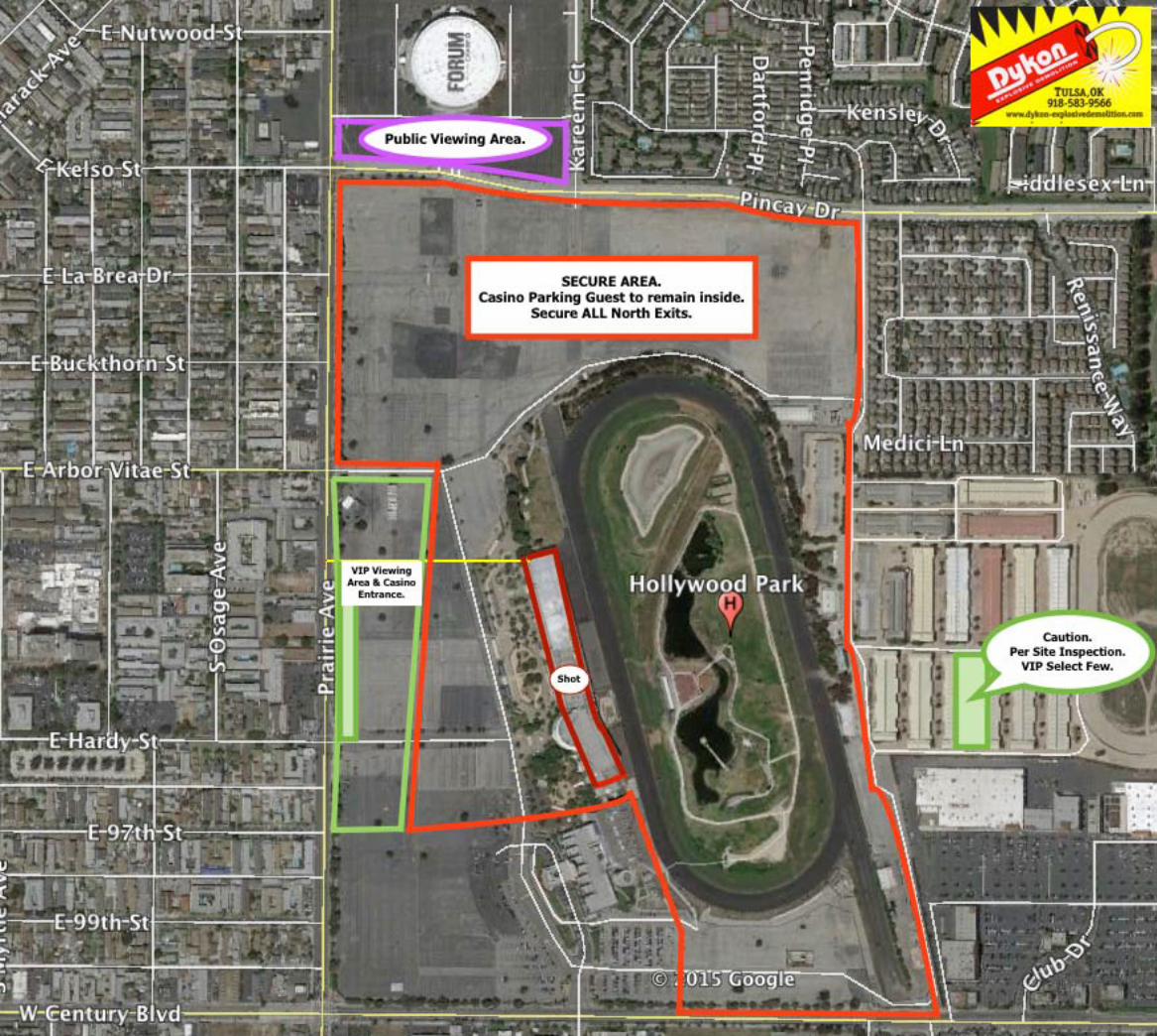
2. BLAST AREA The BLAST AREA and SHOOT COLUMNS are indicated in RED.
3. RECOMENDED EXCLUSION ZONE Note Attachement: 03_Exclusion Zone RED = Blast Area PURPEL = Proposed Exclusion Zone (Security, traffic) No Access during felling event.
DYKON EXPLOSIVE DEMOLITION Corp., Tulsa, OK O: 918 583 9566 Jim Mobile: 918 740 3425 ! of !9 20
COMMERCIAL IN CONFIDENCE. 19 May 2015
4. Type of Explosives used: Detonators. Shaped Charge. Kicker Charge.
Per: Explosive Manufactures & Demolition Industry Best Practices. Product Recommended Safe Practices.
Note Attachment: 4_Dynamite_Kicker Charge.
Dynamite kicker-charges 2_Dynamite_Kicker Charge defines the product used to explosively “Kick” the explosively severed steel, displacing it, so the structure will fail and react as in the designed felling plan. An Extra Gel 1/2 pound net explosive weight (N.E.W.) per 1.25”x8” cartridge will be used, according to proven Best Industry Practices, relative weights subject to the actual size of each individual steel structure column selected for explosive displacement.
LSC_Kicker_Example show the placement, attachment and direction of kick relative to the size and scope of the represented example. Severance and Kick direction are determined by column flange, web orientation and felling direction.
Respective to this project: Typical Kicker Charge N.E.W., per explosively severed steel structure column location, range from 1 pound to 3 pounds N.E.W. kick per explosive severance location. 4 severance locations per column shot.
DYKON EXPLOSIVE DEMOLITION Corp., Tulsa, OK O: 918 583 9566 Jim Mobile: 918 740 3425 ! of !10 20
Kick
COMMERCIAL IN CONFIDENCE. 19 May 2015
Shape Charge Note Attachments:
5_AES_LSC defines the industry leader in manufactured Linear Shaped Charges used to explosively sever steel structures. LSC are selected accordingly to the respective size and scope of the steel structures column to be explosively severed. Steel columns are prepared for shape charges secured at 45 degree severance angle with kicker charges “kicking” severed column away from the angel of severance. Kicker charges are placed on bottom and top severance locations, inside and securely against the columns web to be kicked out. This action allows for controlled, safe and optimal structural failure.
DETONATORS. Nonelectric delayed detonators: used to delay the structural impact between each column felled. 500ms delay between each column.Total event duration time is less than 20 seconds.
Electric Starter Detonator: used to “start” the explosive felling event. Tested and Connected to Column #1 to command and control start the safe felling event from an approved blasting machine.
DYKON EXPLOSIVE DEMOLITION Corp., Tulsa, OK O: 918 583 9566 Jim Mobile: 918 740 3425 ! of !11 20
COMMERCIAL IN CONFIDENCE. 19 May 2015
5.Quantity of Explosives Used for Column Kicker Charges. Note Attachement: 6_LSC Kicker Charge Table
6. Protective Measure Concepts. Column Preparation, Matting Charges. All California State and Federal Blasting regulations will be followed referencing explosive demolition structure felling to Industry Best Practices. 19 CCR 1568.3(a) & 8 CCR 5279(b). The construction of blast coverings capable of preventing fragments from being thrown will be implemented. Non-Conductive protecting matting, coverings and secured / anchored rigid barrier container walls will in-place prior to felling. Non-conductive Flying fragment curtains will be erected prior to felling.
Note Attachments: X_Previous Projects Examples Folder. Slides 8_ trough 14_
Industry proven Steel Column Box construction for LSC and frag protection. Metallic bands and fasteners will secure each box and rubber conveyor belting over explosive charges affixed to each shoot column. A Non-Conductive Geo-Textile Fabric curtain suspended between the Structure and Casino can reduce dust and flying debris.
DYKON EXPLOSIVE DEMOLITION Corp., Tulsa, OK O: 918 583 9566 Jim Mobile: 918 740 3425 ! of !12 20
LSC Dynamite Pound Pound
HollyWood Pk CA 2ft 1.25 x 8 LSC Kicker
0.7" 0.85" 1" 1.5" 1.7" 2" Cord .5# / stk Explosive Charge
Ct Column # Laminate Flange Width 600 900 1200 2000 3200 4000 LSC Pigtails Kickers Weight Weight
* note inches inches Length Inch ea. # Sticks per Column per Column
1 1 1.5 16.500 4 18 4 6 1.714 3
2 2 1.5 4 23 4 6 2.190 3
3 3 1.5 4 23 4 6 2.190 3
4 4 1.500 4 23 4 6 2.190 3
5 5 1.500 4 23 4 6 2.190 3
6 6 1.500 4 23 4 6 2.190 3
7 7 1.500 4 23 4 6 2.190 3
8 8 1.500 4 23 4 6 2.190 3
9 9 1.500 4 23 4 6 2.190 3
10 10 1.500 4 23 4 6 2.190 3
11 11 1.500 4 23 4 6 2.190 3
12 12 1.500 4 23 4 6 2.190 3
13 13 1.500 4 23 4 6 2.190 3
14 14 1.000 2 2 23 4 6 1.752 3
15 15 1 4 23 4 6 1.314 3
16 16 1.000 4 23 4 6 1.314 3
17 17 1.000 4 23 4 6 1.314 3
18 18 1.000 4 23 4 6 1.314 3
19 19 1.000 4 23 4 6 1.314 3
20 20 1.000 4 23 4 6 1.314 3
21
Totals 0 0 26 54 0 0 80 120 37.638 60.000
Total Charge NEW 98.000
COMMERCIAL IN CONFIDENCE. 19 May 2015
DYKON EXPLOSIVE DEMOLITION Corp., Tulsa, OK O: 918 583 9566 Jim Mobile: 918 740 3425 ! of !13 20
COMMERCIAL IN CONFIDENCE. 19 May 2015
8_Double_V_Cut1. Referencing each steel structure columns to be explosively severed, kicked and displaced for controlled felling. LSC angle of severance & Kicker Charge web side placement are designed to “kick” the explosively severed column section with respect to each columns Flange/ Web orientation to the fall side. Industry best practices prove this philosophy works safe.
DYKON EXPLOSIVE DEMOLITION Corp., Tulsa, OK O: 918 583 9566 Jim Mobile: 918 740 3425 ! of !14 20
Kicker Charge
Kicker Charge
Direction of Kick
COMMERCIAL IN CONFIDENCE. 19 May 2015
Note Attachment: 9_DYKON BOX
DYKON EXPLOSIVE DEMOLITION Corp., Tulsa, OK O: 918 583 9566 Jim Mobile: 918 740 3425 ! of !15 20
COMMERCIAL IN CONFIDENCE. 19 May 2015
DYKON EXPLOSIVE DEMOLITION Corp., Tulsa, OK O: 918 583 9566 Jim Mobile: 918 740 3425 ! of !16 20
COMMERCIAL IN CONFIDENCE. 19 May 2015
DYKON EXPLOSIVE DEMOLITION Corp., Tulsa, OK O: 918 583 9566 Jim Mobile: 918 740 3425 ! of !17 20
COMMERCIAL IN CONFIDENCE. 19 May 2015
DYKON EXPLOSIVE DEMOLITION Corp., Tulsa, OK O: 918 583 9566 Jim Mobile: 918 740 3425 ! of !18 20
COMMERCIAL IN CONFIDENCE. 19 May 2015
7. Vibration. Protec is a the third-party seismic surveying company charged with monitoring Ground and Air Vibrations per California Blasting Regulations. A preliminary Vibration Calculation Study may be advisable. Protect conducts a detailed Pre-Blast Survey on all close proximity assets, takes photos, video and issues a detailed final report.
Based on decades of similar explosive felling projects, the previous statements: “not exceeding 0.35in./sec. within 50’ and estimating less than 0.25in./sec. @ 500’ radius” hold true based on generic geology. Generally, ground PPV diminishes with distance form the event… Above ground, un-confined explosive structural demolition shots generate more Air Blast than Ground Vibration. The structures felling impact create ground vibrations. Our Philosophy of approach is to sequentially delay the felling, minimizing the structures impact as such, reducing transmitted ground vibration. Additional ground / grade elevation fall impact zone “padding” and cushioning berms constructed of sand, dirt will reduce transmitted ground vibrations at grade. Padding the impact area is advisable and considered to be used as necessary for planning the felling event.
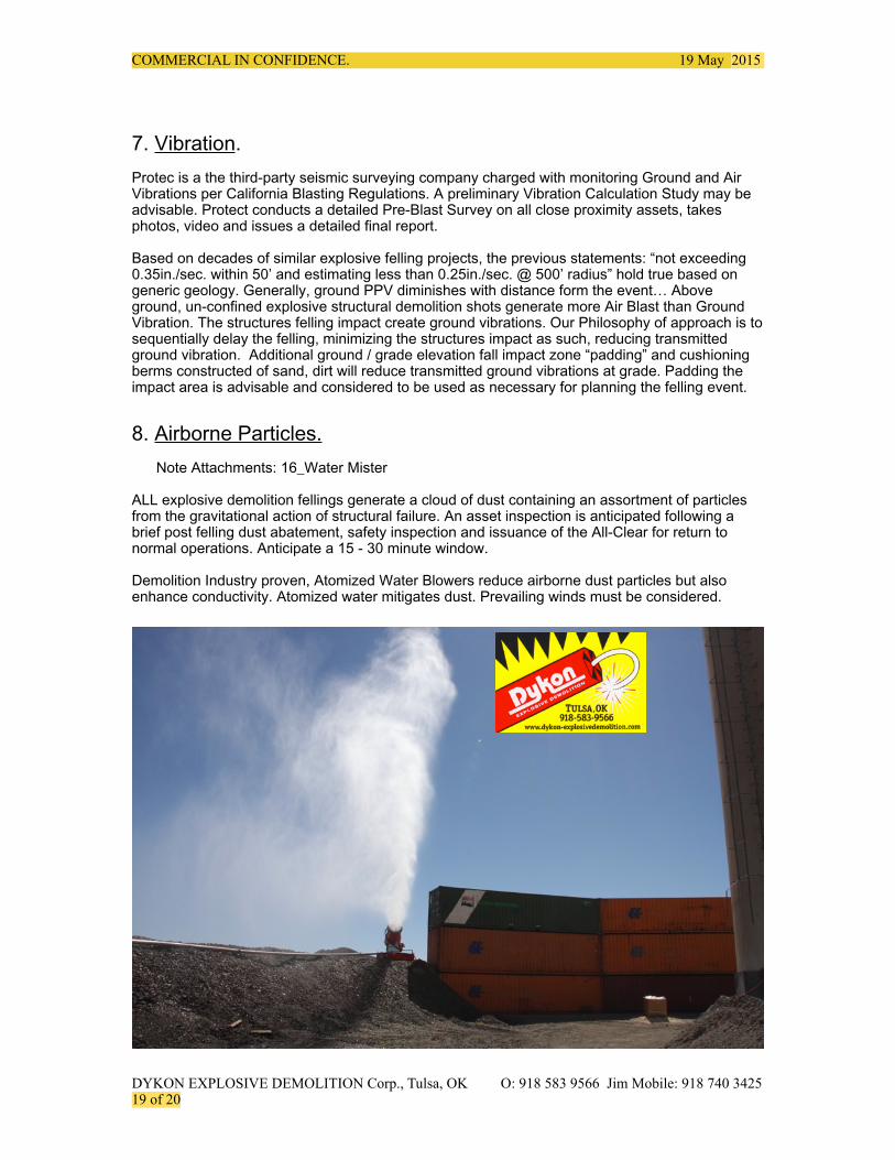
8. Airborne Particles. Note Attachments: 16_Water Mister
ALL explosive demolition fellings generate a cloud of dust containing an assortment of particles from the gravitational action of structural failure. An asset inspection is anticipated following a brief post felling dust abatement, safety inspection and issuance of the All-Clear for return to normal operations. Anticipate a 15 - 30 minute window.
Demolition Industry proven, Atomized Water Blowers reduce airborne dust particles but also enhance conductivity. Atomized water mitigates dust. Prevailing winds must be considered.
DYKON EXPLOSIVE DEMOLITION Corp., Tulsa, OK O: 918 583 9566 Jim Mobile: 918 740 3425 ! of !19 20
COMMERCIAL IN CONFIDENCE. 19 May 2015
It is Demolition Industry Best Practices to fell structures during early mornings hours as calm wind conditions and environmental conditions permit. We highly advise the monitoring of prevailing wind direction and wind speed during final preparations- just prior to the explosive felling event. Should adverse weather conditions exist (winds in access of 11mph blowing towards protected assets, high wind gusts in excess of 35mph or impending storm conditions warrant concern) at the prescribed felling event time; A Stand-Down order will be implemented until such conditions improve. Issuing a Stand-Down Order requires all to remain in-place until the structure is rendered safe by the Blaster in-charge. Preferred (improved, permit-able) weather conditions consist of calm winds at or below 10mph and winds greater than 10mph IF blowing away from protected assets. Local airport, real time weather report monitoring is recommended.
CLOSE Proximity: Electrically Energized Assets. Active Utilities. The safest objective is for any active utility, energized electrical asset, be de-energized during the explosive felling event. Ample time is needed for post airborne particles to dissipate and for post inspections to indicate all-clear for re-energization.
Identify ALL assets and implement protective measures accordingly.
Felling the structure using Explosives or using Conventional methods with electrical assets fully energized is considered NOT in the best interests of public safety and NOT best industry safe practices. Use of Conventional demolition methods also expose all assets to ultrahigh risk. We are open to any suggestions officials may choose to offer up.
9. Misfire Procedures Note Attached: 17_DYKON_Misfire Procedures
10. Insurance & Certificates. Note attachments: 18_Certificate of Insurance 19_Jim_California_Blaster Due to size and scope these documents require an additional file folder.
DYKON’s California Insurance agent can be approached directly for receiving “certified copies” of coverage and addressing content. Contact information is in attachment: 17_Certificate of Insurance.
As with ALL Demolition Industry Explosive fellings, the Blaster in Charge bares ALL blasting activity responsibilities. As such, is liable for same.
Do Not hesitate to contact us.
11. Assorted Photo Examples from previous events. Note Attachments: X_Previous Projects (folder)
DYKON EXPLOSIVE DEMOLITION Corp., Tulsa, OK O: 918 583 9566 Jim Mobile: 918 740 3425 ! of !20 20
Specialty Explosive Demolition Misfire procedures. January, 2015
! Explosive Demolition, Inc.
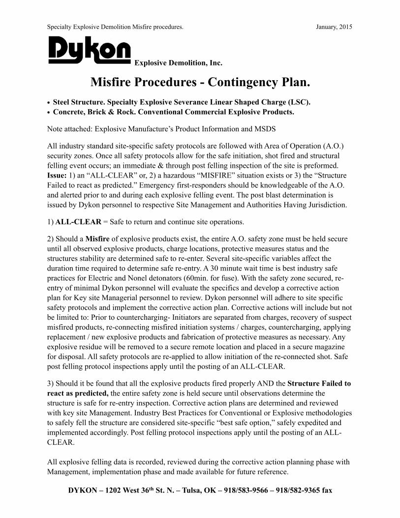
Misfire Procedures - Contingency Plan. • Steel Structure. Specialty Explosive Severance Linear Shaped Charge (LSC). • Concrete, Brick & Rock. Conventional Commercial Explosive Products.
Note attached: Explosive Manufacture’s Product Information and MSDS
All industry standard site-specific safety protocols are followed with Area of Operation (A.O.) security zones. Once all safety protocols allow for the safe initiation, shot fired and structural felling event occurs; an immediate & through post felling inspection of the site is preformed. Issue: 1) an “ALL-CLEAR” or, 2) a hazardous “MISFIRE” situation exists or 3) the “Structure Failed to react as predicted.” Emergency first-responders should be knowledgeable of the A.O. and alerted prior to and during each explosive felling event. The post blast determination is issued by Dykon personnel to respective Site Management and Authorities Having Jurisdiction.
1) ALL-CLEAR = Safe to return and continue site operations.
2) Should a Misfire of explosive products exist, the entire A.O. safety zone must be held secure until all observed explosive products, charge locations, protective measures status and the structures stability are determined safe to re-enter. Several site-specific variables affect the duration time required to determine safe re-entry. A 30 minute wait time is best industry safe practices for Electric and Nonel detonators (60min. for fuse). With the safety zone secured, re-entry of minimal Dykon personnel will evaluate the specifics and develop a corrective action plan for Key site Managerial personnel to review. Dykon personnel will adhere to site specific safety protocols and implement the corrective action plan. Corrective actions will include but not be limited to: Prior to countercharging- Initiators are separated from charges, recovery of suspect misfired products, re-connecting misfired initiation systems / charges, countercharging, applying replacement / new explosive products and fabrication of protective measures as necessary. Any explosive residue will be removed to a secure remote location and placed in a secure magazine for disposal. All safety protocols are re-applied to allow initiation of the re-connected shot. Safe post felling protocol inspections apply until the posting of an ALL-CLEAR.
3) Should it be found that all the explosive products fired properly AND the Structure Failed to react as predicted, the entire safety zone is held secure until observations determine the structure is safe for re-entry inspection. Corrective action plans are determined and reviewed with key site Management. Industry Best Practices for Conventional or Explosive methodologies to safely fell the structure are considered site-specific “best safe option,” safely expedited and implemented accordingly. Post felling protocol inspections apply until the posting of an ALL-CLEAR.
All explosive felling data is recorded, reviewed during the corrective action planning phase with Management, implementation phase and made available for future reference.
DYKON – 1202 West 36th St. N. – Tulsa, OK – 918/583-9566 – 918/582-9365 fax