Embed Size (px)
DESCRIPTION
brake squeal
Citation preview

CHAPTER 1
INTRODUCTION Brakes are one of the most important safety and performance components in
automobiles. Ever since the advent of the automobile, development of brakes has
focused on increasing braking power and reliability. However, the refinement of
vehicle acoustics and comfort through improvement in other aspects of vehicle design
has dramatically increased the relative contribution of brake noise to these aesthetic
and environmental concerns.
The word “Squeal” means loud noise. Disc brake squeal remains an elusive
problem in the automotive industry. A loud noise or high pitched squeal occurs when
the brakes are applied. The frequency ranges for the low-frequency squeal is 1000–
2000 Hz and for high frequency squeal is 2–15 kHz.
Brake noise is an irritant to consumers who may believe that it is symptomatic
of a defective brake and file a warranty claim, even though the brake is functioning
exactly as designed in all other aspects. Thus, noise generation and suppression have
become prominent considerations in brake part design and manufacture. Indeed, many
makers of materials for brake pads spend up to 50% of their engineering budgets on
noise, vibration and harshness.
1.1 DISC BRAKE MECHANICS
An automotive brake system can be divided into three main parts:
The rotor, as the name is indicating, is rotating with the wheel. It is the
first part in the friction couple.
The brake pad is the second, stationary part of the friction couple. During a
brake application the pad is pressed against the rotor with a hydraulic piston.
The friction forces between the stationary pad and the rotating disc will turn
the kinetic energy of the vehicle into heat. The hydraulic system transfers and
amplifies the brake force from the brake pedal to the hydraulic piston pressing the
linings against the rotor.
1

Figure 1.1 Disc Brake (courtesy www.howstuffworks.com)
The brake pads are the rough friction surface that is pressed against the rotor
to stop the wheel. The rotor is a round plate attached to the hub. The piston presses
one brake pad against the wheel, while the caliper presses the other. The caliper is
“floating” because it moves in a track that allows it to center itself over the rotor. As
the brake fluid fills the cylinder, it pushes the piston to the left; however, it also
pushes the caliper to the right. This allows both brake pads to press against the wheel
simultaneously.
1.2 FINITE ELEMENT MODELS
In recent years, the finite element method has become an indispensable tool
for modeling disc brake systems and providing new insights into the problem of brake
squeal. This method provides a natural and straightforward means for generating
finite dimensional approximations to the governing equations of motion for the
components of the brake system. This is accomplished by admitting polynomial
interpolations of the dependent variables (e.g., displacements, temperature) within
each element subdomain. However, contrary to traditional lumped parameter
techniques, the finite element method allows for accurate representation of complex
geometries and boundary/loading conditions. Also, spatially resolved kinematic and
kinetic quantities, such as strains and stresses, are readily computed as part of the
finite element solution. Furthermore, the accuracy of a finite element model is
typically controlled by the analyst, who may choose to refine the approximation in
order to simulate the response of the brake system with a higher degree of fidelity.
2

The finite element method has been employed by researchers in brake squeal studies
to several ends. One of its earlier uses was to investigate the modes and natural
frequencies of the brake rotor. The most common use is to compute the M and K
matrices in models of disc brakes. Subsequently, a linear eigenvalue analysis is
conducted to determine the system’s frequencies, modes, and stability.
1.3 REASONS FOR BRAKE SQUEAL
Most brake squeal is produced by vibration (resonance instability) of the
brake components, especially the pads and discs (known as force-coupled
excitation).
The callipers and brake pads, which squeeze the brake rotors to make the car
stop, can't get an even grip on a warped rotor hence, vibration.
Cold weather combined with high early-morning humidity (dew) often
worsens brake squeal. Dust on the brakes may also cause squeal.
1.4 PROBLEMS DUE TO SQUEAL
Overall brake squeal can be annoying to the vehicle passengers, passers-by,
pedestrians, etc. especially as vehicle designs become quieter.
Squeaky brakes can panic a driver.
Warranty claims by the customer.
1.5 METHODOLOGY OF WORK FLOW
Figure 1.2 Flowchart of Work flow
3
Literature Survey
Problem Identification
Disc Brake 3D model
Meshing of the
Assembled Drawing
Frequency Analysis

CHAPTER 2
LITERATURE SURVEY2.1 Analysis of brake squeal noise using the finite element method
Roberto Jordan, et al.,[1] This paper summarizes the application of complex
eigenvalue analysis in a finite element model of a commercial brake system. The
effect of the operational parameters (friction coefficient, braking pressure and brake
temperature) and wear on the dynamic stability of the brake system is examined. The
results show that the effect of brake temperature changes the coupling mechanisms
between rotor and pad, which in some cases can be useful in order to reduce the
instabilities and generated noise. Wear is an operational condition that has a strong
effect on the system instability, since stiffness properties of brake pads are influenced
by the changes on geometry and on the friction material, leading to high-frequency
noise generation.
2.2 Analysis of Disc Brake Noise at High and Low Frequency with the Effect of
the Friction
Ammar A. Yousif, et al., [2] This paper is a study on the stick-slip oscillation
of a discrete system with contact interaction as a friction curve. The stick-slip
oscillation with a single degree-of-freedom was examined by means of numerical
time integration , while that with two degrees was by using FEM method. Beam on
rotating disc was used to investigate the effect of friction at low velocity. The
response indicated that the friction ratio was responsible for the separation amplitude
value. The plate on disc was modelled and connected by using matrix27 to investigate
the effect of friction on a high frequency system. The results showed that friction
causes damping at low frequency while at high frequency, it may generate the squeal.
2.3 Linear eigenvalue analysis of the disc-brake squeal problem
Q. Cao1, H. Ouyang1 et al, [3] This paper presents a numerical method to
calculate the unstable frequencies of a car disc brake and suggests a suitable analysis
procedure. The stationary components of the disc brake are modelled using finite
elements and the disc as a thin plate. The separate treatments of the stationary
components and the rotating disc facilitate the modelling of the disc brake squeal as a
4

moving load problem. Some uncertain system parameters of the stationary
components and the disc are tuned to fit experimental results. A linear, complex-
valued, asymmetric eigenvalue formulation is derived for the friction-induced
vibration of the disc brake. Predicted unstable frequencies are compared with
experimentally established squeal frequencies of a real car disc brake.
2.4 Finite Element Analysis of Thermal elastic Instability of Disc Brakes
JW. S Chung et al [4] In this study, the thermoelastic instability (TEI) was
analyzed using the finite element analysis technique. The governing dynamic and heat
equations were described. Three dimensional thermo mechanical analysis model of
the disc brake system were created. An intermediate processor based on the staggered
approached was used to exchange result data: temperature, friction contact power,
nodal displacement and deformation. Disc thickness variation (DTV) and temperature
distribution of the disc were calculated, and the tendency and meaning of each result
were discussed.
2.5 Analysis of disc brake squeal using the Complex Eigenvalue method
P. Liu et al [5]. In this paper, a new functionality of ABAQUS/Standard,
which allows for a nonlinear analysis prior to a complex eigenvalue extraction in
order to study the stability of brake systems, is used to analyse disc brake squeal. An
attempt is made to investigate the effects of system parameters, such as the hydraulic
pressure, the rotational velocity of the disc, the friction coefficient of the contact
interactions between the pads and the disc, the stiffness of the disc, and the stiffness
of the back plates of the pads, on the disc squeal. The simulation results show that
significant pad bending vibration may be responsible for the disc brake squeal.
2.5 CONCLUSION FROM LITERATURE SURVEY
The effect of some operational parameters on the stability characteristics of a
disc brake such as High friction coefficients increases the degree of system instability.
Brake temperature had the effect of reducing the brake pad stiffness, altering the
coupling mechanisms between the rotor and pad. In some cases, this effect can be
useful. An increase in temperature led to an increase in the damping loss factor of the
brake pads. Wear is an operational condition that must be considered in numerical
models, since it has a strong effect on the stability characteristics The effect of a non-
5

conservative (as a friction force) tends to couple the two modes. These effects make
the system able to exchange energy in a way that causes the unstable behaviour of the
brake system to continue. It can be observed that the effects of friction coefficient
enforce the system to generate the squeal at lower frequency from the stable separate
modes. Complex eigenvalue analysis is more useful in finding the unstable frequency
which causes squeal.
2.6 OBJECTIVE
To perform Static analysis for the application of brake pressure.
Static analysis to impose a rotational velocity on the disc.
To extract the natural frequency of the system.
Complex eigenvalue analysis to extract unstable modes and identify the onset
of squeal frequency.
To vary the operational parameters such as friction coefficient, pressure,
contact stiffness and angular velocity and its effect on squeal frequency.
6

CHAPTER 3
BRAKE SQUEAL ANALYSIS
3.1 BRAKE NOISE GENERATION MECHANISM
Disc brake squeal occurs when a system experiences vibrations with a very
large mechanical amplitude. There are two theories that attempt to explain why this
phenomenon occurs. The first theory states that brake squeal is a result of a stick–slip
mechanism . An opposing theory states that high levels of vibration result from
geometric instabilities of the brake system assembly.
An example of stick-slip is a squeaky door hinge. During the stick phase, the
brake lining and cast iron move together, with no slippage at the interface. The stick
time period is variable, depending on speed, load, and system stiffness. When slip
begins, a noise burst occurs, this involves a half-cycle of motion at the rubbing
surface. The sudden energy burst often produces a more sustained audible oscillation.
Figure 3.1 Stick Slip effect
Both theories, however, attribute the brake system vibration and the
accompanying audible noise to variable friction forces at the pad–rotor interface.
According to the first hypothesis, the stick–slip theory, a variable friction coefficient
with respect to sliding velocity between pads and rotor, provides the energy source for
the brake squeal. Several studies based on this theory were conducted when disc
brakes were first used on automobiles. Squeal noise was found to be more likely when
the decreasing relationship between the friction coefficient and the sliding velocity
become pronounced. An increase in the negative slope did not always increase the
7

occurrence of squeal, however, the need for an alternative or accompanying theory
was revealed.
In the case of geometric instability, the second theory, the variable friction
forces are caused by variable normal forces. Even if the coefficient of friction is
constant, variable friction forces are still possible. In this case, two system modes that
are geometrically matched move closer in frequency as the friction coefficient
increases. These two modes eventually couple at the same frequency and become
unstable.
3.2 ANALYSIS OF BRAKE SQUEAL NOISE USING FEM
The stability of the system of equations, according to the geometric stability
hypothesis, reflects the likelihood of squeal for the brake system modelled. Several
techniques for evaluating the stability of a system are available. Approaches
considered were (a) a transient solution of the dynamic equations of motion, (b)
evaluation of the Routh criterion, and (c) an eigenvalue analysis of the system. A
divergent transient solution indicates that instabilities are present in the system.
Likewise, the Routh criterion demonstrates whether or not a system is stable. Such
solutions, however, provide no insight into how the structure could be altered to
remove the instability.
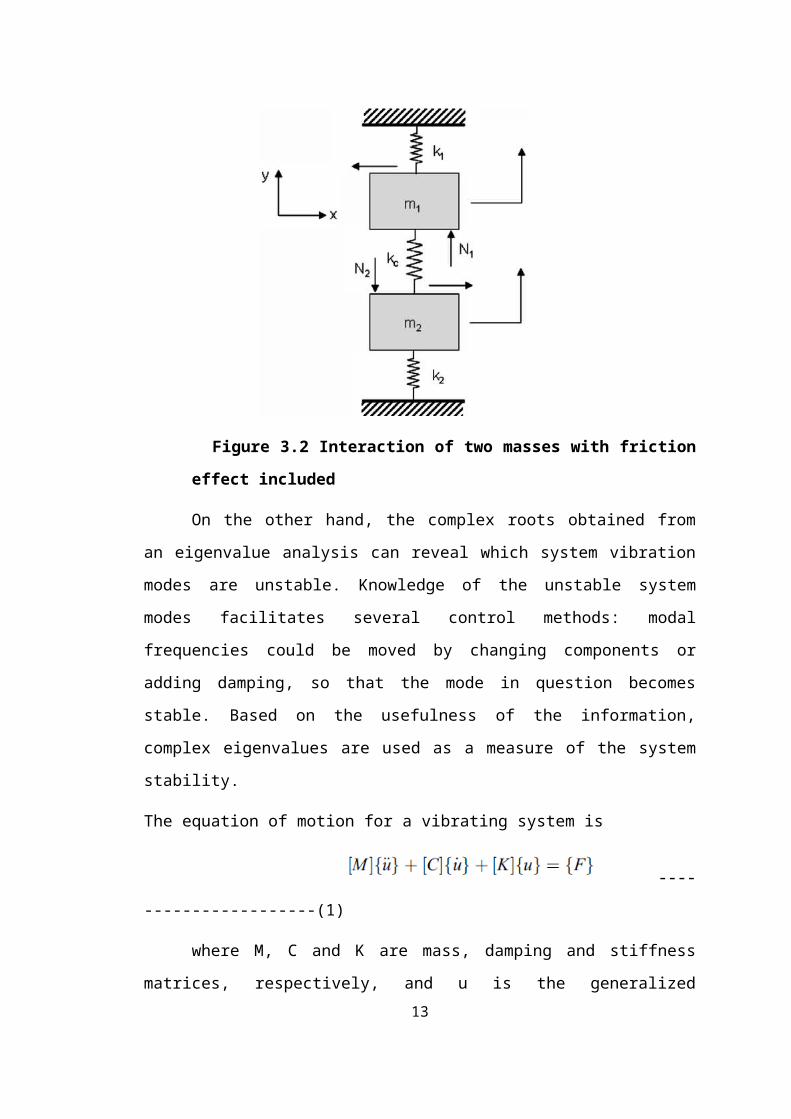
Figure 3.2 Interaction of two masses with friction effect included
8
On the other hand, the complex roots obtained from an eigenvalue analysis
can reveal which system vibration modes are unstable. Knowledge of the unstable
system modes facilitates several control methods: modal frequencies could be moved
by changing components or adding damping, so that the mode in question becomes
stable. Based on the usefulness of the information, complex eigenvalues are used as a
measure of the system stability.
The equation of motion for a vibrating system is
----------------------(1)
where M, C and K are mass, damping and stiffness matrices, respectively, and
u is the generalized displacement vector. For friction induced vibration, it is assumed
that the forcing function F is mainly contributed to by the variable friction force at the
pad–rotor interface. The friction interface is modeled as an array of friction springs as
shown in Fig. 3. With this simplified interface model, the force vector becomes linear.
----------------------(2)
where Kf is the friction stiffness matrix. A homogeneous equation is the
obtained by combining Eqs. (1) and (2) and by moving the friction term to the left-
hand side:
-----------------------(3)
3.3 COMPLEX EIGENVALUE ANALYSIS
The complementary solution to the homogenous, second order, matrix
differential equation above (3) is in the form of
------------------------(4)
Performing the appropriate differentiations and substituting into Eq. (3) yields
the complex eigenvalue problem:
-------------------------(5)
9

Non-trivial solutions for the displacement occur only where the matrix in
parenthesis is singular. This matrix is singular only for certain values of S, called
complex eigenvalues.
The arbitrary scaled solution vectors corresponding to each eigenvalue are the
eigenvectors. They may or may not be complex. These eigenvectors reveal the
relative shape of the oscillatory motion for each solution, or mode, including the
phase relationship between points in the system if they are complex. The eigenvalues
and the eigenvectors of Eq. (5) may be complex, consisting of both a real and
imaginary part. For underdamped systems the eigenvalues always occur in complex
conjugate pairs. For a particular mode the eigenvalue pair is
-------------------------(6)
where is the real part and is the imaginary part for the ith mode. The
motion for each mode can be described in terms of the complex conjugate eigenvalue
and eigenvector:
--------------------------(7)
Thus and are the damping coefficient and damped natural frequency
describing damped sinusoidal motion. If the damping coefficient is negative, decaying
oscillations typical of a stable system result. A positive damping coefficient, however,
causes the amplitude of oscillations to increase with time. Therefore the system is not
stable when the damping coefficient is positive. By examining the real part of the
system eigenvalues the modes that are unstable and likely to produce squeal are
revealed.Variable friction force with variable normal force (interface element) – The
contact stiffness element used in the model describes the interaction between adjacent
nodes of the disc and pads. This is probably the only work which shows, through a
clear and solid based explanation, all the procedures involved in the construction of an
FEM model to analyze disc brake squeal noise.
The friction element must be able to model:
The steady state friction force acting at the interface of the components the
steady state reaction force acting in the normal direction.
10

The varying part of the normal force which is proportional to the stiffness of
the element and the relative displacement of the adjacent nodes and the varying part
of the friction force which is related to the varying normal force according to
Amonton’s law
------------------------(8)
Figure 3.3 A pad coupled to the disc face model with friction elements
Figure 3.4 The effect of normal displacement on the variable normal force
Node 1 represents one of the nodes on the disc face and node 2 is the adjacent node on
the brake pad friction face as shown here in Fig4.3. When perturbed, nodes 1 and 2
move relative to each other, causing a variable force on node 2, which is a function of
11

the relative displacement between the two nodes and the contact stiffness. In the case
where both nodes move further apart.The equation of motion representing the
interaction of nodes 1 and 2 can therefore be used as the basis of the interface
element.
at node 1 (pad friction face):
Fx1 = µkc(y1-y2) …………………..(9)
Fy1 = kc(y1-y2) .…………………(10)
at node 2 (rotor friction face):
Fx2 = -Fx1 ………………….(11)
Fy2 = -Fy1 ………………….(12)
Thus arranging the nodal stiffness relationship in a matrix form:
2.1. COMPLEX EIGENVALUE EXTRACTION
For brake squeal analysis, the most important source of nonlinearity is the
frictional sliding contact between the disc and the pads. ABAQUS allows for a
convenient, but general definition of contact interfaces by specifying the contact
surface and the properties of the interfaces. ABAQUS version 6.10 has developed a
new approach of complex eigenvalue analysis to simulate the disc brake squeal.
Starting from preloading the brake, rotating the disc, and then extracting natural
frequencies and complex eigenvalues, this new approach combines all steps in one
seamless run. The complex eigen problem is solved using the subspace projection
method, thus a natural frequency extraction must be performed first in order to
determine the projection subspace. The governing equation of the system is
----------------------------(13)
12
Where M is the mass matrix, C is the damping matrix, which includes friction-
induced contributions, and K is the stiffness matrix, which is unsymmetric due to
friction. The governing equation can be rewritten as
------------------------------(14)
where μ is the eigenvalue and Φ is the corresponding eigenvector. Both eigenvalues
and eigenvectors may be complex. In order to solve the complex eigen problem, this
system is symmetrized by ignoring the damping matrix C and the unsymmetric
contributions to the stiffness matrix K. Then this symmetric eigenvalue problem is
solved to find the projection subspace. The N eigenvectors obtained from the
symmetric eigenvalue problem are expressed in a matrix as [Φ1, . . . ,ΦN]. Next, the
original matrices are projected onto the subspace of N eigenvectors
---------------(15)
and
-----------------(16)
Then the projected complex eigen problem becomes
------------------------(17)
Finally, the complex eigenvectors of the original system can be obtained by
-----------------------------(18)
If the damping ratio is negative, the system becomes unstable, and vice versa. The
main aim of this analysis is to reduce the damping ratio of the dominant unstable
modes.
13

CHAPTER-4
FINITE ELEMENT MODEL
4.1 SOLID WORK MODELING
The Solid Works Part Design application makes it possible to design precise
3D parts with an intuitive flexible user interface, from sketching in an assembly
context to iterative detailed design. Part Design application will enable you to
accommodate design requirements for parts of various complexities, from simple to
advance.
4.2 DIMENSIONS OF DISC
Figure 4.1 Illustrated disc brake dimensions (all the dimensions in mm)
14

Figure 4.2 3D model disc and pad
Figure 4.3 3D model of disc and pad
4.3 MESHINIG
Hypermesh software highly flexible finite element analysis software. Its important feature is its meshing capability and its flexibility to interact with other geometrical analysis software.
15

Figure 4.4 Meshed Model Disc brake pad
Figure 4.5 Meshed Model of Disc
16

CHAPTER-5
RESULTS AND DISCUSSION
The effects of the system parameters, such as the hydraulic pressure P, the
rotational velocity of the disc W, the friction coefficient of the contact interactions
between the pads and the disc u, the stiffness of the disc, and the stiffness of the back
plates of the pads, on the disc squeal are investigated by the simulation model. The
complex eigenvalue analysis is performed up to 9 kHz which is the range of squeal
occurrence for the present disc model. As mentioned previously, if the damping ratio
is negative, the system becomes unstable, and vice versa; when the disc system is
unstable, the squeal propensity increases with an increased value of the damping
ratio . For clarity, only damping ratio and frequency are plotted. The typical values for
the system parameters used in the simulation are: P = 0.5 MPa, W = 0.5rad/s, u = 0.3,
ED= 210GPa, TD = 5mm, and EP = 210 GPa. Analysis is carried out in Abaqus 6.10,
by changing the values of each parameter while retaining the respective typical values
for the others.
Mode number Real Part
Frequency in hertz
Damping Ratio
1 -5.06 1352 0.0544923082 10.23 1450 -0.102723313 -6.31 1750 0.05249924 -18.12 2256 0.1169446815 -22.98 2487 0.1345351036 0 2985 07 -10.09 2998 0.0490028028 -31.41 3158 0.1448162139 -2.31 3198 0.010517073
10 -1.83 3548 0.00750980811 -4.5 3874 0.01691275212 -0.9 4268 0.00307029113 -100.8 4396 0.33385987314 -3.25 4500 0.01051555615 -0.03 4987 8.75877E-0516 -0.98 5023 0.00284069317 80.37 5896 -0.1984713718 -33.46 6245 0.07801082519 -55.93 6350 0.12824264620 -75.9 6678 0.165484277
Table 5.1 Frequency output17

13521750
24872998
31983874
43964987
58966350
-0.3
-0.2
-0.1
0
0.1
0.2
0.3
0.4
friction=0.3
Figure 5.1 Damping ratio vs frequency
The unstable modes are figure 5.3 mode numbers 2,17 with frequency of
1450,5896Hz with negative damping ratio. These frequency causes squeal and
instability to the system.
Figure 5.2 Unstable mode shapes at mode number 2, 17 with frequency 1450,
5896Hz respectively.
5.1 EFFECT OF FRICTION COEFFICIENT
Disc squeal is believed to be caused mainly by friction-induced dynamic
instability. This section presents the effect of the friction coefficient of the contact
interactions between the pads and the disc on the disc squeal, in which the friction
coefficient u varies from 0.3 to 0.8. Fig. 5.2 shows results in the form of the damping
ratio as a function of frequency for different friction coefficients.
18
Frequency Hz
Dam
pin
g R
atio
Stable region
Unstable region

1405
1669
1983
2355
2798
3325
3950
4694
5576
6625
-0.6
-0.4
-0.2
0
0.2
0.4
0.6
friction=0.3friction=0.5friction=0.8
Figure 5.3 Frequency output vs damping ratio for varying friction
coefficient
Figure 5.4 Unstable mode shapes at mode number 6, 20 with frequency
12134,7131Hz respectively when friction coefficient is 0.5
Figure 5.5 Unstable mode shapes at mode number 3,18,19 with frequency 1669,
6078, 6625Hz respectively when friction coefficient is 0.8
19
Dam
pin
g R
atio
Frequency HzUnstable region

It is understandable that with an increase in the friction coefficient, there is an
accompanying increase in the instability of the system, thus an increase in the
damping ratios. This means that the most fundamental method of eliminating brake
squeal is to reduce the friction between the disc and pad. However, this obviously
reduces braking performance and is not a preferable method to employ. The unstable
modes are figure 5.3 mode 2,17 for friction coefficient 0.3, figure 5.4 mode 6,20 for
friction coefficient 0.5 and figure 5.5 mode 3,18,19 for friction coefficient 0.8.The
corresponding mode shapes represents how the disk brake vibration takes place
whether it is in plane or out bound and its frequency are onset of squeal.
5.2 EFFECT OF BRAKE PRESSURE
The effect of the hydraulic pressure P on the squeal propensity is studied by
varying P from 0.5MPa to 1.5MPa. Figure 5.6 shows the change of the damping ratio
with frequency for different hydraulic pressures. The major squeal frequency is
approximately 7 kHz. It can be seen from Figure 5.6 that with an increase in P, the
value of the damping ratio is increased, so the squeal propensity is increased. This is
due to a larger hydraulic pressure inducing more friction between the pads and the
disc. However, the simulation results also show that the effect of the hydraulic
pressure on the disc brake squeal is not significant because the value of the damping
ratio only changes from 0.11 to 0.23 when P increases from 0.5MPa to 1.5MPa.
1405
1689
2022
2420
2896
3466
4148
4965
5943
7113
-0.4
-0.3
-0.2
-0.1
0
0.1
0.2
0.3
0.4
0.5
0.6
pressure=0.5MPapressure=1.5MPapressure=1.5MPa
Figure 5.6 Frequency output vs damping ratio for varying Brake Pressure
20
Frequency Hz
Dam
ping
ra
tio
Unstable region

Figure 5.7 Unstable mode shapes at mode number 3, 5 with frequency 1632,
1789Hz respectively when brake pressure is 1Mpa.
Figure 5.8 Unstable mode shapes at mode number 1, 3, 18, 19 with frequency
1405, 1689, 6502, 7189Hz respectively when brake pressure is 1.5Mpa.
5.3 EFFECT OF ANGULAR VELOCITY
1419
1838
2379
3080
3988
5164
6688
-0.3
-0.2
-0.1
0
0.1
0.2
0.3
0.4
angular velocity=0.5angular velocity=3angular velocity=3
Figure 5.9 Frequency output vs damping ratio for varying angular
velocity
21
Dam
ping
ra
tio
Frequency Hz

Figure 5.9 presents the variation of the damping ratio with the frequency for different
disc angular velocities W (0.5–3.0 rad/s). The dominant squeal frequency is
approximately 6kHz. As the angular velocity increases, the value of the damping ratio
gradually decreases. However, as with the previous case, when changing the hydraulic
pressure, the effect of changing the angular velocity on the squeal propensity is also
not obvious: this can be seen from figure 5.10 which shows the value of the damping
ratio varies with an increase in the rotational velocity of the disc. Here the unstable
modes are mode number 3, 18 for 1.5rad/sec and mode number 3, 19 for 3rad/sec.
The squeal frequency is 1651, 6018 for 1.5ard/sec and 1686, 5689 for 3rad/sec.
5.4 EFFECT OF STIFFNESS OF THE BACK PLATES OF THE PAD
1501
1783
2118
2517
2991
3553
4222
5016
5959
7080
-0.6
-0.4
-0.2
0
0.2
0.4
0.6
back plate youngs modulus=150MPaback plate youngs modulus=180MPaback plate youngs modulus=210MPa
Figure 5.10 Frequency output vs damping ratio for varying back plate
youngs modulus
Brake pads consist of contact plates which are made of a friction material and back
plates. In this study, the effect of Young’s modulus EP the back plates of the pads on
the disc squeal is investigated, in which EP= 150 to 210Mpa the typical value of
Young’s modulus for the back plates of pads. Figure 5.10 shows results of the
damping ratio versus frequency for different Young’s moduli of back plate. It can be
seen that the dominant squeal occurs at a frequency of approximately 6-7kHz. As
Young’s modulus EP, is increased, corresponding to an increase in stiffness of the 22
Dam
ping
ratio
Frequency Hz
Unstable region

back plates of the pads, the value of the damping ratio increases significantly as
shown. This important observation implies that the stiffer back plates of pads cause a
higher squeal propensity. This is so since the friction material connected to the back
plates is very soft compared with the back plate material. Hence the higher the
stiffness of the back plates, the greater the uneven deformation and vibration
magnitude of the pad, and hence the higher the damping ratio. So an effective method
to reduce squeal propensity of disc brake system is to use a damping material for the
back plates of the pads. When youngs modulus of plate at 180GPa there are three
unstable modes at frequency 2376, 5629, 6136Hz and at 210GPa there are four
unstable modes at frequency 1686, 1783, 5016, 7717Hz.Here the damping ratio
increases from 0.10 to 0.42 as modulus increases, thereby increasing squeal
propensity.
Figure 5.11 Unstable mode shapes at mode number 2, 3 with frequency 1686,
1783, 5016, 7717Hz respectively when back plate modulus is 210GPa.
23

Figure 5.12 Unstable mode shapes at mode number 15, 20 with frequency 5016,
7717Hz respectively when back plate modulus is 210GPa.
5.5 UNSTABLE MODES OF DISC BRAKE SYSTEM
The simulation results show that for all the cases owe large damping ratios, the
unstable frequencies are approximately 5-7kHz. There is a significant pad bending
vibration for these cases. Figure 5.13 gives an example of the vibration mode of the
disc brake system at a frequency of 7kHz, where all the system parameters are the
typical values. It can be seen that the disc has only slight out-of-plane modes of
vibration as shown in Figure 5.13, but the pads have serious out-of-plane modes of
vibration which occur mainly at the bottom parts of the pads as shown in Figure 5.13.
This suggests that the brake pads may be the source of the disc brake squeal. So
methods which can reduce the pad bending vibration should be used to eliminate the
disc squeal. One of the methods reported is to use viscoelastic material (damping
material) on the back of the back plates of the pads and another effective method is to
modify the shape of the brake pads to change the coupling between the pads and the
disc . Except the unstable vibration modes which occur at frequency 5-7kHz and are
caused mainly by the pads vibration, the other unstable vibration modes are caused
mainly by the disc vibration. Figure 5.13 give an example of the unstable vibration
mode of the disc brake system at the frequency of 7717Hz, where all the system
parameters are the typical values. It can be seen that the disc has significant out-of-
plane vibration compared with the vibration of pads.
24

Figure 5.13 Vibration mode of the disc brake system at frequency
7717 Hz.
5.6 SQUEAL INDEX
From the eigenvalues analysis, the instability levels and the eigen frequencies
are calculated. The instability level (degree of instability) is defined as the real part of
the eigenvalue α =Re [λ] and the eigen frequency is defined as the imaginary part of
the eigen value ω =Im[λ] Hz. Some authors took the instability level as a squeal
propensity and others do not. In this work the squeal propensity (σ) that is the squeal
index will be taken as
σ = (α2+ ω2)1/2 .sin ( δ/ 2 ) -----------------()
The eigen frequencies will be taken as ω/2π Hz. Where δ is the phase angle.
δ = tan-1(Imaginary part/real part)----------------()
25

1000 2000 3000 4000 5000 6000 7000 8000
-1000
-800
-600
-400
-200
0
200
400
600
800
1000
friction=0.3
friction=0.5
friction=0.8
Figure 5.14. Effect of friction coefficient on brake squeal noise and frequency respectively
Figure 5.14 indicates the effect of friction coefficient on brake squeal noise and
degree of instability. As the friction coefficient increases from 0.3 to 0.8 the squeal
index also increases from 50 to 900. The highest squeal index for 912 for frequency of
7721Hz is obtained for friction coefficient 0.8. In figure 5.15 the modulus of elasticity
of the back plate is increased from 150 to 210GPa. It can be noted from the figure that
as the Young’s modulus back plate increases the squeal index decreases from 75 to
973. The lower value of squeal index of 85 and 89 occurred Young’s modulus of
150GP and 180GPa respectively. The squeal index can be reduced by decreasing the
friction coefficient and youngs modulus of back plate.
26
Sque
al In
dex
Frequency Hz

0 2000 4000 6000 8000 10000
-1500
-1000
-500
0
500
1000
1500
back plate youngs modulus=150GPaback plate youngs modulus=180GPaback plate youngs modulus=210GPa
Figure 5.14. Effect of back plate modulus on brake squeal noise and frequency respectively
The squeal index is more for frequency range of 5-7kHz and when the real part of eigen value is more.
CHAPTER-6
27
Sque
al In
dex
Frequency Hz

CONCLUSION
Friction-induced disc brake squeal is investigated using the new function of
ABAQUS version 6.10, which combines a static analysis and a complex eigenvalue
extraction method. The nonlinear effects can be taken into account in the preloading
steps in order to more accurately model a deformed configuration at which a complex
eigenvalue analysis is performed. The systematic analysis here shows that significant
pad bending vibration may be responsible for causing the disc brake squeal and the
major squeal frequency is approximately 5-7kHz for the present disc brake system.
The effects of the friction between the pads and the disc, the stiffness of the disc, and
the stiffness of the back plates of the pads, on disc squeal, are significant, but the
effects of the hydraulic pressure and the angular velocity of the disc on disc squeal are
not obvious. The squeal can be reduced by decreasing the friction coefficient,
increasing the stiffness of the disc, using damping material on the back of the pads,
and modifying the shape of the brake pads.
SCOPE FOR FUTURE WORK
To include the temperature effect between pad and rotor because an increase
in temperature can sometimes suppress squeal frequency.
To include the piston calliper assembly in finite model and do the frequency
analysis and change the area of contact between pad and disc.
Try to add damping material on back plate so that it can reduce the onset of
squeal frequency.
REFERENCES
28

[1] Analysis of brake squeal noise using the finite element method: A parametric
study Ma´rio Tricheˆs Ju´ nior, Samir N.Y. Gerges *, Roberto Jordan Federal Applied
Acoustics 69 (2008) 147–162.
[2] Automotive Drum Brake Squeal Analysis Using Complex Eigenvalue Methods
Ibrahim Ahmed 1, Essam Allam2, Mohamed Khalil2 and Shawki Abouel-
International Journal of Modern Engineering Research Vol.2, Issue.1, pp-179-199,
Jan-Feb 2012 ISSN: 2249-6645.
[3] Automotive disc brake squeal N.M. Kinkaid, O.M. O’Reilly, P. Papadopoulos
Journal of Sound and Vibration 267 (2003) 105–166.
[4] Analysis of Disc Brake Noise at High and Low Frequency with the Effect of the
Friction Ammar A. Yousif and Inzarulfaisham Abd Australian Journal of Basic and
Applied Sciences, 5(3): 209-218, 2011 ISSN 1991-8178.
[5] Analysis of Disc Brake squeal using complex eigen value method P. Liu, H.
Zheng journal on Applied Acoustics 68 (2007) 603–615.
29