Embed Size (px)
Citation preview
E 7
.700
.10
/10.
13
Filtration in Industrial Processing.
2
E 7
.700
.10
/10.
13
NoteThe information in this brochure relates to the operating conditions and applications described.
For applications and operating conditions not described, please contact the relevant technical department.
Subject to technical modifications.
Introduction Page
Your Partner in the Filtration of Process Media 3Industries and Applications 6
Filter Element TechnologyFilter Materials 7Filter Elements 9Special Features of Filter Element Technology 10
Product OverviewAutomatic Back-flushing Filters AutoFilt® 11Inline and Screen Basket Filters 12Gas Filters 14System Solutions 15Clogging Indicators 16
Know-howProcess Media 17
Selecting the Correct Process Filter 21
AppendixFilter Specification Questionnaire 22
ATEX Check List 23
Contents
3
E 7
.700
.10
/10.
13
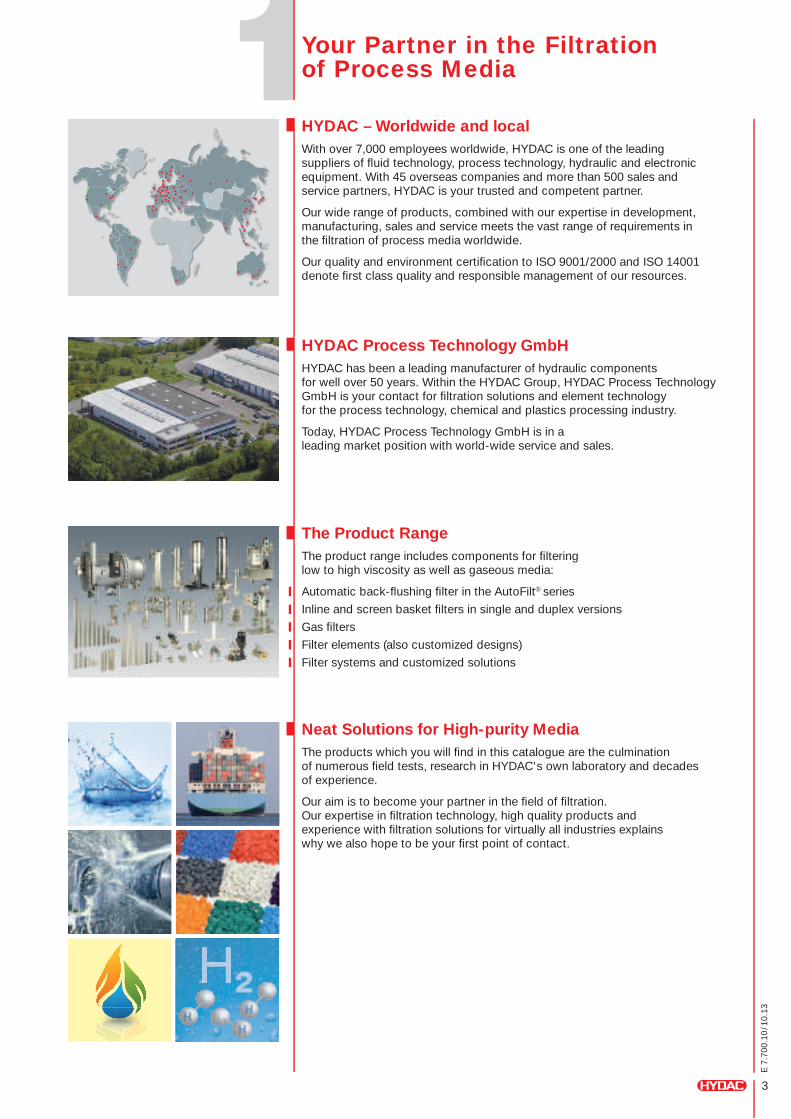
HYDAC – Worldwide and localWith over 7,000 employees worldwide, HYDAC is one of the leading suppliers of fluid technology, process technology, hydraulic and electronic equipment. With 45 overseas companies and more than 500 sales and service partners, HYDAC is your trusted and competent partner.
Our wide range of products, combined with our expertise in development, manufacturing, sales and service meets the vast range of requirements in the filtration of process media worldwide.
Our quality and environment certification to ISO 9001/2000 and ISO 14001 denote first class quality and responsible management of our resources.
HYDAC Process Technology GmbH HYDAC has been a leading manufacturer of hydraulic components for well over 50 years. Within the HYDAC Group, HYDAC Process Technology GmbH is your contact for filtration solutions and element technology for the process technology, chemical and plastics processing industry.
Today, HYDAC Process Technology GmbH is in a leading market position with world-wide service and sales.
The Product Range The product range includes components for filtering low to high viscosity as well as gaseous media:
Automatic back-flushing filter in the AutoFilt® series
Inline and screen basket filters in single and duplex versions
Gas filters
Filter elements (also customized designs)
Filter systems and customized solutions
Neat Solutions for High-purity MediaThe products which you will find in this catalogue are the culmination of numerous field tests, research in HYDAC's own laboratory and decades of experience.
Our aim is to become your partner in the field of filtration. Our expertise in filtration technology, high quality products and experience with filtration solutions for virtually all industries explains why we also hope to be your first point of contact.
Your Partner in the Filtration of Process Media
H
4
E 7
.700
.10
/10.
13
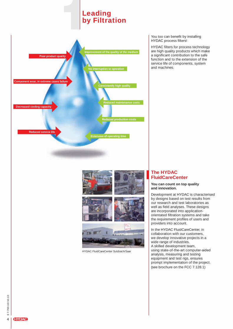
Poor product qualityImprovement of the quality of the medium
No interruption to operation
Consistently high quality
Reduced maintenance costs
Reduced production costs
Extension of operating time
Component wear, in extreme cases failure
Decreased cooling capacity
Reduced service life
You too can benefit by installing HYDAC process filters!
HYDAC filters for process technology are high quality products which make a significant contribution to the safe function and to the extension of the service life of components, system and machines.
HYDAC FluidCareCenter Sulzbach/Saar
The HYDAC FluidCareCenterYou can count on top quality and innovation.
Development at HYDAC is characterised by designs based on test results from our research and test laboratories as well as field analyses. These designs are incorporated into application-orientated filtration systems and take the requirement profiles of users and providers into account.
In the HYDAC FluidCareCenter, in collaboration with our customers, we develop innovative projects in a wide range of industries. A skilled development team, using state-of-the-art computer-aided analysis, measuring and testing equipment and test rigs, ensures prompt implementation of the project.(see brochure on the FCC 7.128.1)
Leading by Filtration
5
E 7
.700
.10
/10.
13
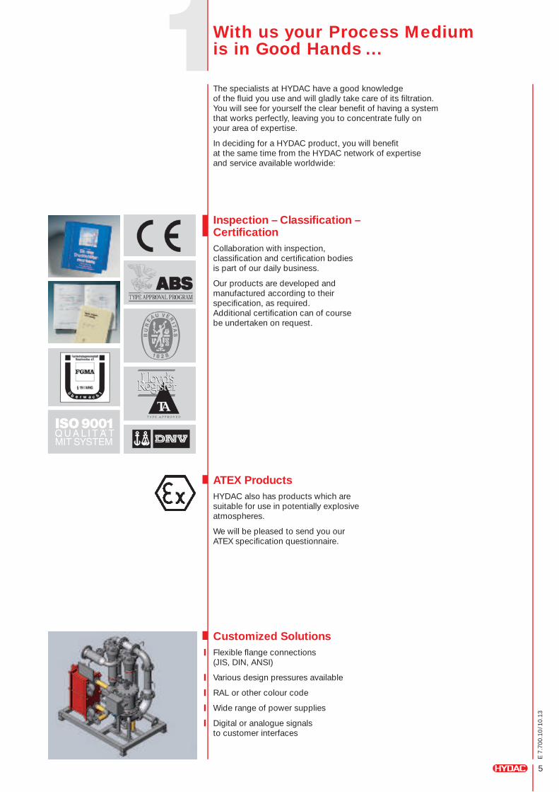
Inspection – Classification – CertificationCollaboration with inspection, classification and certification bodies is part of our daily business.
Our products are developed and manufactured according to their specification, as required. Additional certification can of course be undertaken on request.
ATEX ProductsHYDAC also has products which are suitable for use in potentially explosive atmospheres.
We will be pleased to send you our ATEX specification questionnaire.
Customized SolutionsFlexible flange connections (JIS, DIN, ANSI)
Various design pressures available
RAL or other colour code
Wide range of power supplies
Digital or analogue signals to customer interfaces
The specialists at HYDAC have a good knowledge of the fluid you use and will gladly take care of its filtration. You will see for yourself the clear benefit of having a system that works perfectly, leaving you to concentrate fully on your area of expertise.
In deciding for a HYDAC product, you will benefit at the same time from the HYDAC network of expertise and service available worldwide:
With us your Process Medium is in Good Hands ...
6
E 7
.700
.10
/10.
13
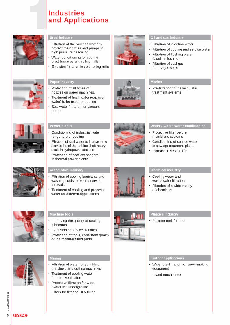
Steel industry
• Filtration of the process water to protect the nozzles and pumps in high pressure descaling
• Water conditioning for cooling blast furnaces and rolling mills
• Emulsion filtration in cold rolling mills
Paper industry
• Protection of all types of nozzles on paper machines.
• Treatment of fresh water (e.g. river water) to be used for cooling
• Seal water filtration for vacuum pumps
Power plants
• Conditioning of industrial water for generator cooling
• Filtration of seal water to increase the service life of the turbine shaft rotary seals in hydropower stations
• Protection of heat exchangers in thermal power plants
Automotive industry
• Filtration of cooling lubricants and washing fluids to extend service intervals
• Treatment of cooling and process water for different applications
Machine tools
• Improving the quality of cooling lubricants
• Extension of service lifetimes
• Protection of tools, consistent quality of the manufactured parts
Mining
• Filtration of water for sprinkling the shield and cutting machines
• Treatment of cooling water for mine ventilation
• Protective filtration for water hydraulics underground
• Filters for filtering HFA fluids
Oil and gas industry
• Filtration of injection water
• Filtration of cooling and service water
• Filtration of flushing water (pipeline flushing)
• Filtration of seal gas for dry gas seals
Marine
• Pre-filtration for ballast water treatment systems
Water / waste water conditioning
• Protective filter before membrane systems
• Conditioning of service water in sewage treatment plants
• Increase in service life
Chemical industry
• Cooling water and waste water filtration
• Filtration of a wide variety of chemicals
Plastics industry
• Polymer melt filtration
Further applications
• Water pre-filtration for snow-making equipment
... and much more
Industries and Applications
7
E 7
.700
.10
/10.
13
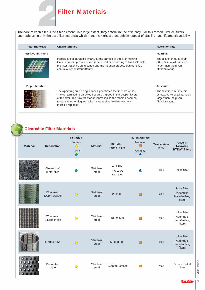
Cleanable Filter Materials
Material Description
Filtration
Surface
Depth
MaterialFiltration
rating in µm
Retention rate
Nominal
Absolute
Temperature in °C
Used in following
HYDAC filters
Chemicron®
metal fibreStainless
steel
1 to 100
0.5 to 25 for gases
400 Inline filter
Wire mesh (Dutch weave)
Stainless steel
25 to 60 400
Inline filter
Automatic back-flushing
filters
Wire mesh Square mesh
Stainless steel
100 to 500 400
Inline filter
Automatic back-flushing
filters
Slotted tubeStainless
steel50 to 3,000 400
Inline filter
Automatic back-flushing
filters
Perforated plate
Stainless steel
3,000 to 10,000 400Screen basket
filter
The core of each filter is the filter element. To a large extent, they determine the efficiency. For this reason, HYDAC filters are made using only the best filter materials which meet the highest standards in respect of stability, long life and cleanability.
Filter materials Characteristics Retention rate
Surface filtration: Nominal:
Particle are separated primarily at the surface of the filter material. Once a pre-set pressure drop is achieved or according to fixed intervals, the filter materials are cleaned and the filtration process can continue continuously or intermittently.
The test filter must retain 90 – 95 % of all particles larger than the given filtration rating.
Depth filtration: Absolute:
The operating fluid being cleaned penetrates the filter structure. The contaminating particles become trapped in the deeper layers of the filter. The flow resistance increases as the media becomes more and more clogged, which means that the filter element must be replaced.
The test filter must retain at least 99 % of all particles larger than the given filtration rating.
Filter Materials
8
E 7
.700
.10
/10.
13
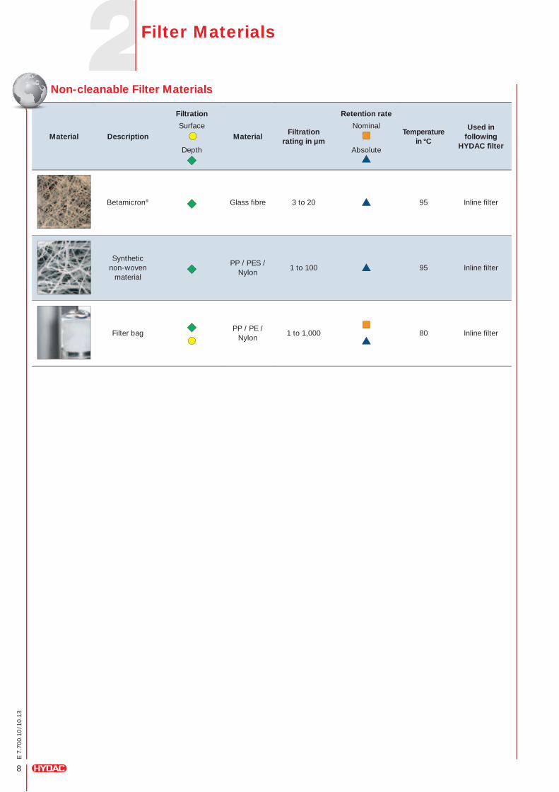
Filter Materials
Non-cleanable Filter Materials
Material Description
Filtration
Surface
Depth
MaterialFiltration
rating in µm
Retention rate
Nominal
Absolute
Temperature in °C
Used in following
HYDAC filter
Betamicron® Glass fibre 3 to 20 95 Inline filter
Synthetic non-woven
material
PP / PES / Nylon
1 to 100 95 Inline filter
Filter bagPP / PE /
Nylon1 to 1,000 80 Inline filter
9
E 7
.700
.10
/10.
13
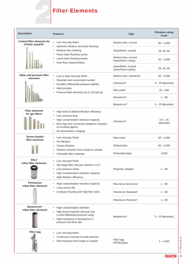
Description Features TypeFiltration rating
in µm
Conical filter elements for HYDAC AutoFilt®
• Low viscosity fluids
• Isokinetic filtration and back-flushing
• Residue-free cleaning
• Fewer back-flushing cycles
• Lower back-flushing losses
• Even flow characteristics
Slotted tube, conical 50 – 3,000
SuperMesh, conical 25, 40, 60
Slotted tube, conical, SuperFlush coating 50 – 3,000
SuperMesh, conical, SuperFlush coating 25, 40, 60
Inline and pressure filter elements
• Low to high viscosity fluids
• Standard and customised models
• Excellent differential pressure stability
• High porosity
• Pressure filter elements up to 210 bar ∆p
Slotted tube, cylindrical 50 – 3,000
Chemicron® 3 – 20 (absolute)
Wire mesh 25 – 500
Flexmicron® 1 – 90
Betamicron® 3 – 20 (absolute)
Filter elements for gas filters
• High level of defined filtration efficiency
• Low pressure drop
• High contamination retention capacity
• End caps and connection adaptors crimped – no bonding agents
• No electrostatic charging
Chemicron® 0.5 – 25 (absolute)
Screen basket filter elements
• Low viscosity fluids
• Pre-filtration
• Coarse filtration
• Filtration direction from inside to outside
• Cleanable filter materials
Wire mesh 25 – 1,000
Slotted tube 50 – 3,000
Perforated plate 3,000
PELF Inline filter elements
• Low viscosity fluids
• Very large filter area per element >5 m2
• Low pressure drops
• High contamination retention capacity
• High filtration efficiency
Polyester, pleated 1 – 90
Flexmicron Inline filter elements
• High contamination retention capacity
• Long service life
• Compact housing with high flow rates
Flexmicron Economy® 1 – 90
Flexmicron Standard® 1 – 90
Flexmicron Premium® 1 – 90
Betamicron® Inline filter elements
• High contamination retention
• High level of particle removal over a wide differential pressure range
• High resistance to fluctuations in pressure and flow rate
Betamicron® 3 – 20 (absolute)
Filter bag • Low viscosity fluids
• Continuous removal of solid particles
• Flow direction from inside to outside Filter bag PP/PE/Nylon
1 – 1,000
Filter Elements
10
E 7
.700
.10
/10.
13
Description Features
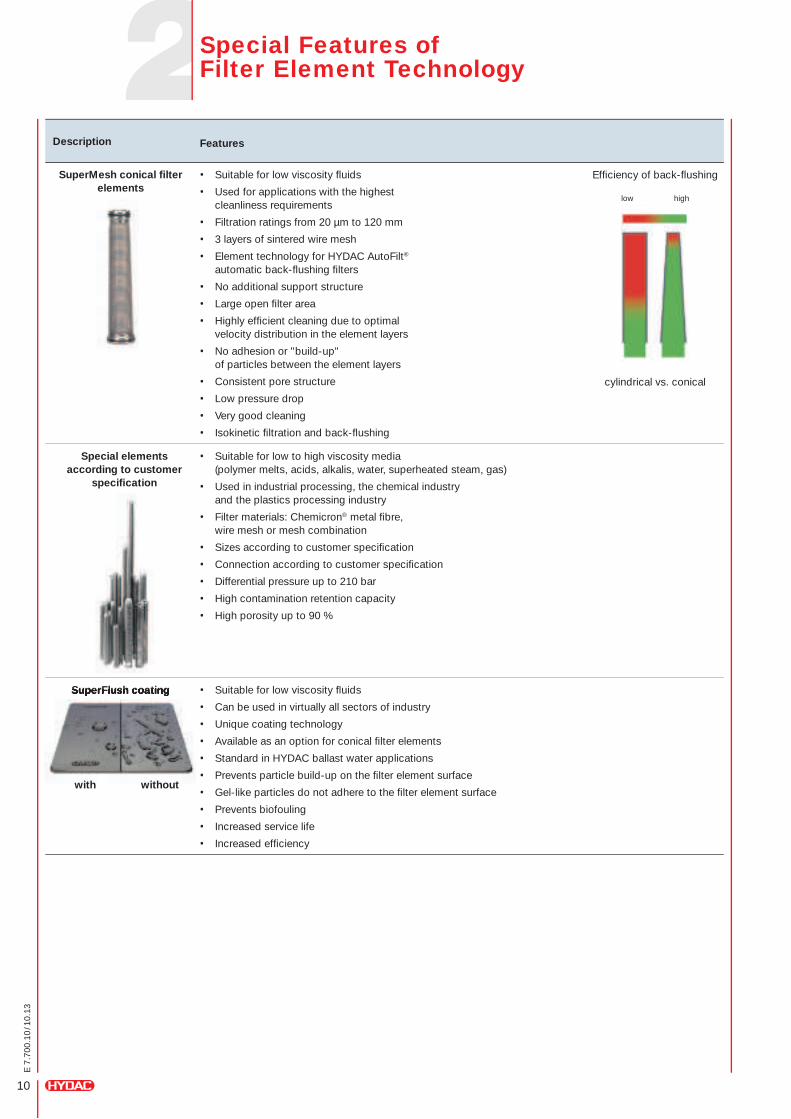
SuperMesh conical filter elements
• Suitable for low viscosity fluids
• Used for applications with the highest cleanliness requirements
• Filtration ratings from 20 µm to 120 mm
• 3 layers of sintered wire mesh
• Element technology for HYDAC AutoFilt® automatic back-flushing filters
• No additional support structure
• Large open filter area
• Highly efficient cleaning due to optimal velocity distribution in the element layers
• No adhesion or "build-up" of particles between the element layers
• Consistent pore structure
• Low pressure drop
• Very good cleaning
• Isokinetic filtration and back-flushing
Special elements according to customer
specification
• Suitable for low to high viscosity media (polymer melts, acids, alkalis, water, superheated steam, gas)
• Used in industrial processing, the chemical industry and the plastics processing industry
• Filter materials: Chemicron® metal fibre, wire mesh or mesh combination
• Sizes according to customer specification
• Connection according to customer specification
• Differential pressure up to 210 bar
• High contamination retention capacity
• High porosity up to 90 %
SuperFlush coatingSuperFlush coating
with without
• Suitable for low viscosity fluids
• Can be used in virtually all sectors of industry
• Unique coating technology
• Available as an option for conical filter elements
• Standard in HYDAC ballast water applications
• Prevents particle build-up on the filter element surface
• Gel-like particles do not adhere to the filter element surface
• Prevents biofouling
• Increased service life
• Increased efficiency
low high
Efficiency of back-flushing
cylindrical vs. conical
Special Features of Filter Element Technology

11
E 7
.700
.10
/10.
13
Flow rate Qmax
Operating pressure Pmax
Filtration ratings Filter element type
AutoFilt® RF3
10,000 m3/h 100 bar 25 to 3,000 µm
• Conical slotted tube• Wire mesh• SuperMesh• SuperFlush coating optional
AutoFilt® RF4
220 l/min 16 bar 25 to 1,000 µm
• Conical slotted tube• Wire mesh• SuperMesh• SuperFlush coating optional
AutoFilt® RF5
4,200 m3/h 10 bar 200 to 3,000 µm • Conical slotted tube
AutoFilt® RF7
7,500 m3/h 10 bar 25 to 3,000 µm
• Conical slotted tube• Wire mesh• SuperMesh• SuperFlush coating optional
AutoFilt® RF10
3,000 m3/h 6 bar 40 to 3,000 µm
• Conical slotted tube• Wire mesh• SuperMesh• SuperFlush coating optional /
Standard in ballast water applications
AutoFilt® ATF
400 m3/h 16 bar 200 to 3,000 µm• Conical slotted tube• SuperFlush coating optional
AutoFilt® RFH
800 l/min 350 bar 25 to 500 µm• Slotted tube• Wire mesh
HYDAC automatic back-flushing filters AutoFilt® are designed for continuous or intermittent filtration in all areas of industry and in water treatment. HYDAC AutoFilt® automatic back-flushing filters are self-cleaning systems for the removal of solid particles from fluids. They make a great contribution to operational reliability and reduce operating and maintenance costs.
• Temperatures up to 90 °C• Pressures up to 350 bar• Filtration ratings from 15 to 10,000 µm• Flow rates up to 10,000 m3/h
Automatic Back-flushing Filter AutoFilt®
12
E 7
.700
.10
/10.
13
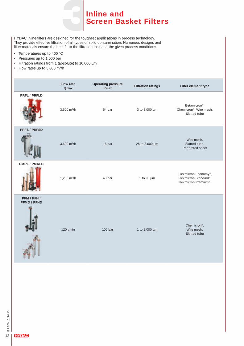
Flow rate Qmax
Operating pressure Pmax
Filtration ratings Filter element type
PRFL / PRFLD
3,600 m3/h 64 bar 3 to 3,000 µmBetamicron®,
Chemicron®, Wire mesh, Slotted tube
PRFS / PRFSD
3,600 m3/h 16 bar 25 to 3,000 µmWire mesh,
Slotted tube, Perforated sheet
PMRF / PMRFD
1,200 m3/h 40 bar 1 to 90 µmFlexmicron Economy®, Flexmicron Standard®, Flexmicron Premium®
PFM / PFH / PFMD / PFHD
120 l/min 100 bar 1 to 2,000 µmChemicron®, Wire mesh, Slotted tube
HYDAC inline filters are designed for the toughest applications in process technology. They provide effective filtration of all types of solid contamination. Numerous designs and filter materials ensure the best fit to the filtration task and the given process conditions.
• Temperatures up to 400 °C• Pressures up to 1,000 bar• Filtration ratings from 1 (absolute) to 10,000 µm• Flow rates up to 3,600 m3/h
Inline and Screen Basket Filters
13
E 7
.700
.10
/10.
13
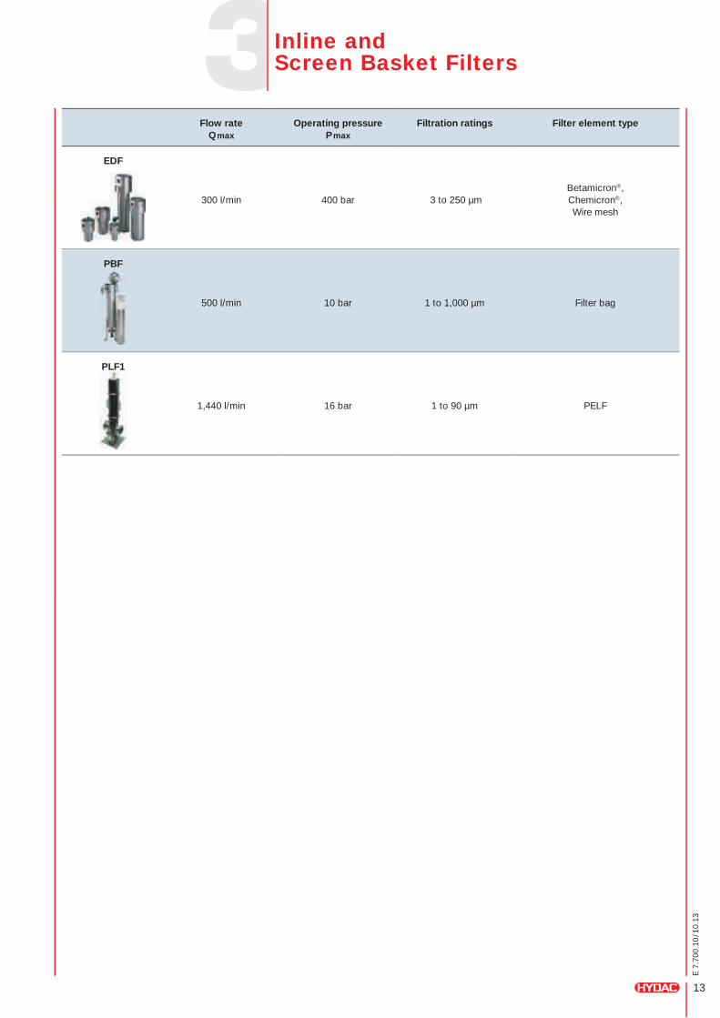
Flow rate Qmax
Operating pressure Pmax
Filtration ratings Filter element type
EDF
300 l/min 400 bar 3 to 250 µmBetamicron®, Chemicron®, Wire mesh
PBF
500 l/min 10 bar 1 to 1,000 µm Filter bag
PLF1
1,440 l/min 16 bar 1 to 90 µm PELF
Inline and Screen Basket Filters
14
E 7
.700
.10
/10.
13
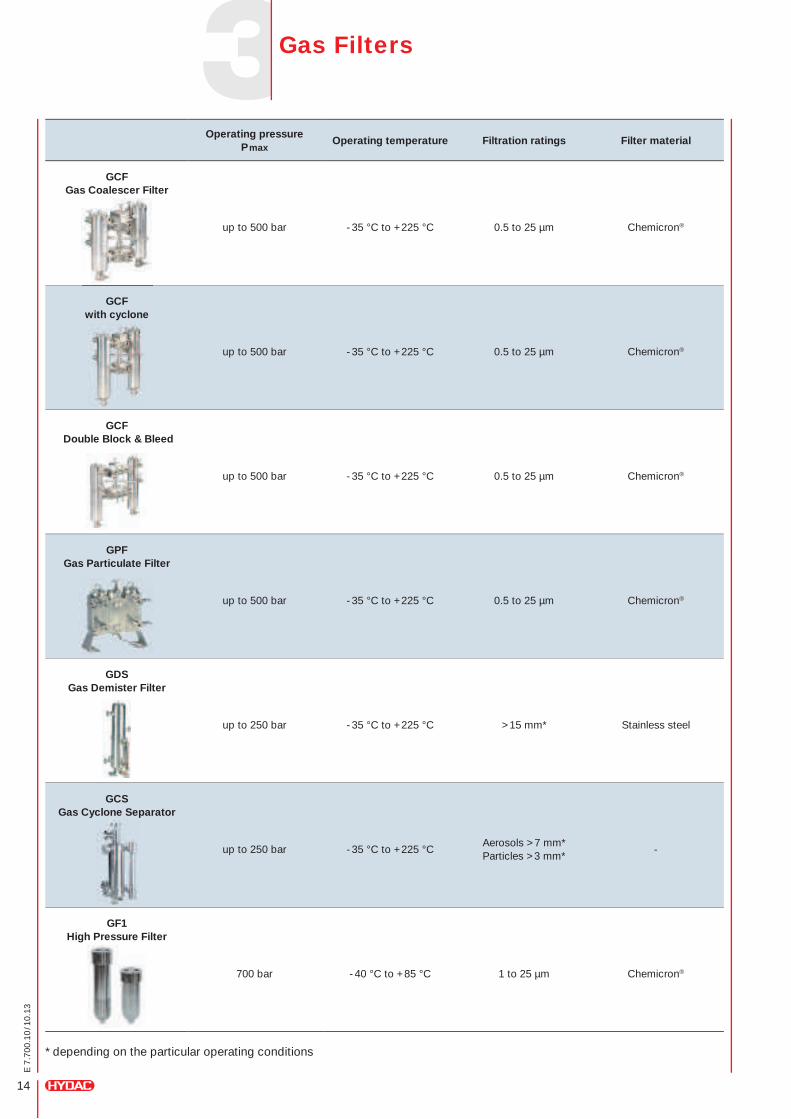
Operating pressure Pmax
Operating temperature Filtration ratings Filter material
GCF Gas Coalescer Filter
up to 500 bar -35 °C to +225 °C 0.5 to 25 µm Chemicron®
GCF with cyclone
up to 500 bar -35 °C to +225 °C 0.5 to 25 µm Chemicron®
GCF Double Block & Bleed
up to 500 bar -35 °C to +225 °C 0.5 to 25 µm Chemicron®
GPF Gas Particulate Filter
up to 500 bar -35 °C to +225 °C 0.5 to 25 µm Chemicron®
GDS Gas Demister Filter
up to 250 bar -35 °C to +225 °C > 15 mm* Stainless steel
GCS Gas Cyclone Separator
up to 250 bar -35 °C to +225 °CAerosols > 7 mm* Particles > 3 mm*
-
GF1 High Pressure Filter
700 bar -40 °C to +85 °C 1 to 25 µm Chemicron®
* depending on the particular operating conditions
Gas Filters
15
E 7
.700
.10
/10.
13
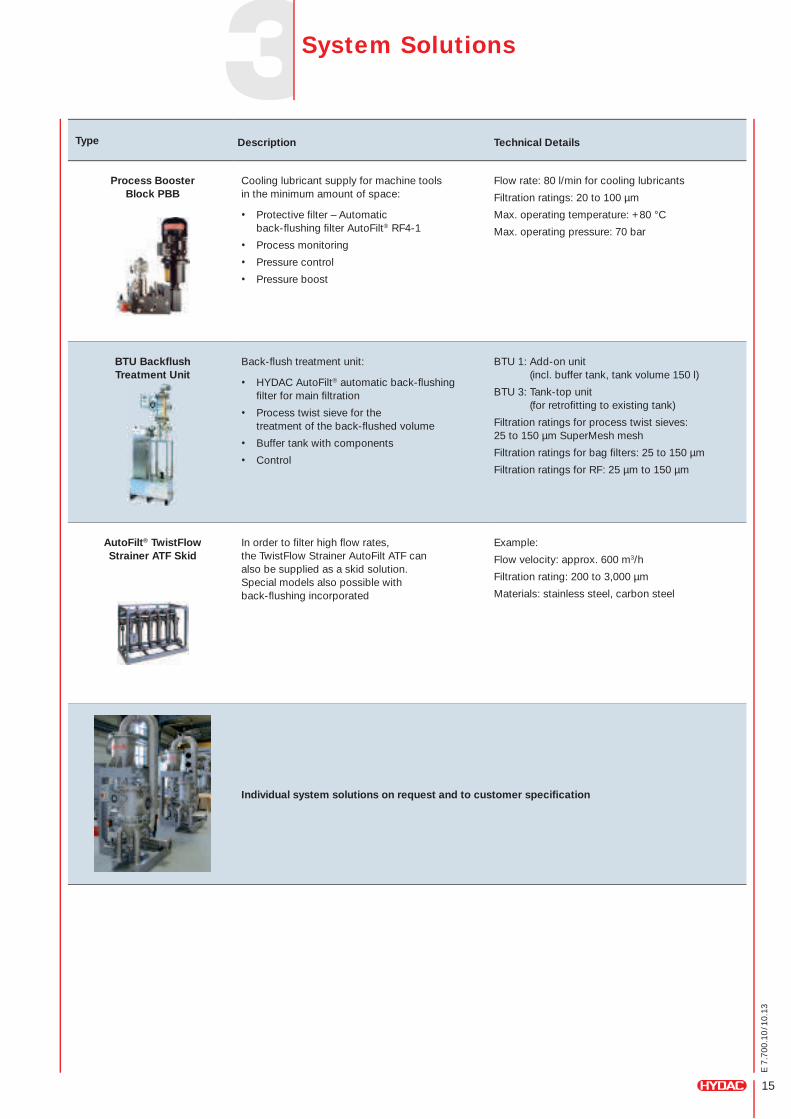
Type Description Technical Details
Process Booster Block PBB
Cooling lubricant supply for machine tools in the minimum amount of space:
• Protective filter – Automatic back-flushing filter AutoFilt® RF4-1
• Process monitoring
• Pressure control
• Pressure boost
Flow rate: 80 l/min for cooling lubricants
Filtration ratings: 20 to 100 µm
Max. operating temperature: +80 °C
Max. operating pressure: 70 bar
BTU Backflush Treatment Unit
Back-flush treatment unit:
• HYDAC AutoFilt® automatic back-flushing filter for main filtration
• Process twist sieve for the treatment of the back-flushed volume
• Buffer tank with components
• Control
BTU 1: Add-on unit (incl. buffer tank, tank volume 150 l)
BTU 3: Tank-top unit (for retrofitting to existing tank)
Filtration ratings for process twist sieves: 25 to 150 µm SuperMesh mesh
Filtration ratings for bag filters: 25 to 150 µm
Filtration ratings for RF: 25 µm to 150 µm
AutoFilt® TwistFlow Strainer ATF Skid
In order to filter high flow rates, the TwistFlow Strainer AutoFilt ATF can also be supplied as a skid solution. Special models also possible with back-flushing incorporated
Example:
Flow velocity: approx. 600 m3/h
Filtration rating: 200 to 3,000 µm
Materials: stainless steel, carbon steel
Individual system solutions on request and to customer specification
System Solutions
16
E 7
.700
.10
/10.
13
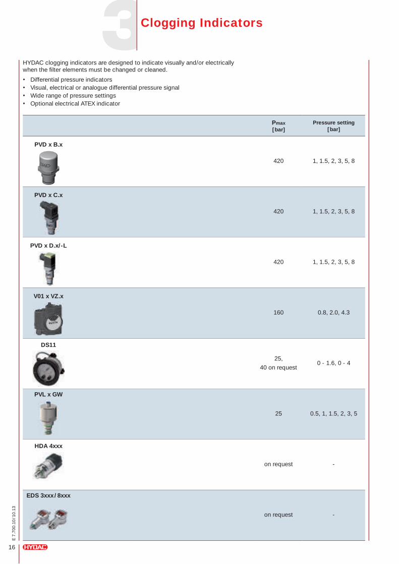
HYDAC clogging indicators are designed to indicate visually and/or electrically when the filter elements must be changed or cleaned.
• Differential pressure indicators• Visual, electrical or analogue differential pressure signal• Wide range of pressure settings• Optional electrical ATEX indicator
Pmax [bar]
Pressure setting [bar]
PVD x B.x
420 1, 1.5, 2, 3, 5, 8
PVD x C.x
420 1, 1.5, 2, 3, 5, 8
PVD x D.x/-L
420 1, 1.5, 2, 3, 5, 8
V01 x VZ.x
160 0.8, 2.0, 4.3
DS11
25,
40 on request0 - 1.6, 0 - 4
PVL x GW
25 0.5, 1, 1.5, 2, 3, 5
HDA 4xxx
on request -
EDS 3xxx / 8xxx
on request -
Clogging Indicators
17
E 7
.700
.10
/10.
13
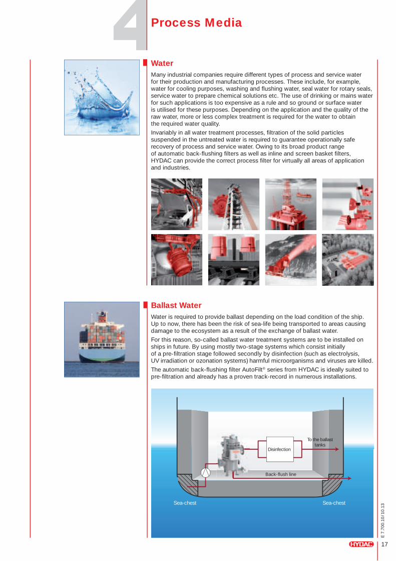
WaterMany industrial companies require different types of process and service water for their production and manufacturing processes. These include, for example, water for cooling purposes, washing and flushing water, seal water for rotary seals, service water to prepare chemical solutions etc. The use of drinking or mains water for such applications is too expensive as a rule and so ground or surface water is utilised for these purposes. Depending on the application and the quality of the raw water, more or less complex treatment is required for the water to obtain the required water quality.
Invariably in all water treatment processes, filtration of the solid particles suspended in the untreated water is required to guarantee operationally safe recovery of process and service water. Owing to its broad product range of automatic back-flushing filters as well as inline and screen basket filters, HYDAC can provide the correct process filter for virtually all areas of application and industries.
Ballast WaterWater is required to provide ballast depending on the load condition of the ship. Up to now, there has been the risk of sea-life being transported to areas causing damage to the ecosystem as a result of the exchange of ballast water.
For this reason, so-called ballast water treatment systems are to be installed on ships in future. By using mostly two-stage systems which consist initially of a pre-filtration stage followed secondly by disinfection (such as electrolysis, UV irradiation or ozonation systems) harmful microorganisms and viruses are killed.
The automatic back-flushing filter AutoFilt® series from HYDAC is ideally suited to pre-filtration and already has a proven track-record in numerous installations.
Disinfection
Back-flush line
Sea-chestSea-chest
To the ballast tanks
Process Media
18
E 7
.700
.10
/10.
13
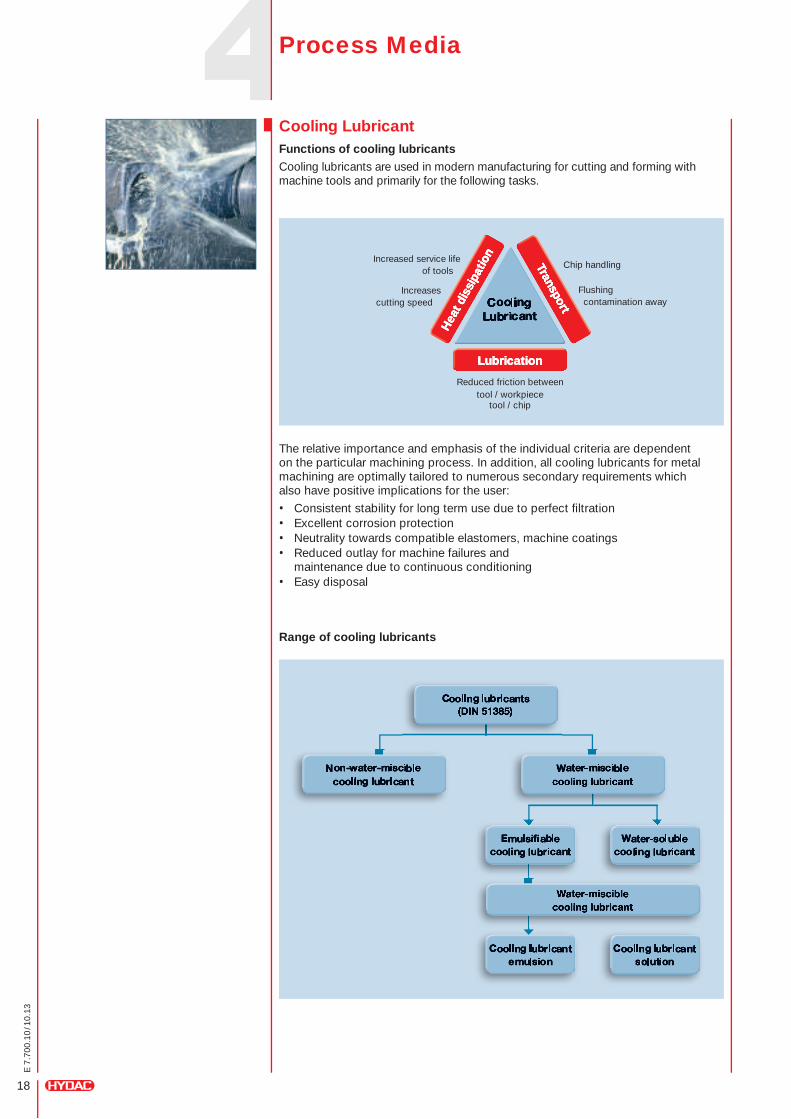
Cooling Lubricant Functions of cooling lubricantsCooling lubricants are used in modern manufacturing for cutting and forming with machine tools and primarily for the following tasks.
LubricationLubricationLubrication
Transport
Transport
Transport
Hea
t dis
sipa
tion
Hea
t dis
sipa
tion
Hea
t dis
sipa
tion
The relative importance and emphasis of the individual criteria are dependent on the particular machining process. In addition, all cooling lubricants for metal machining are optimally tailored to numerous secondary requirements which also have positive implications for the user:
• Consistent stability for long term use due to perfect filtration• Excellent corrosion protection• Neutrality towards compatible elastomers, machine coatings• Reduced outlay for machine failures and
maintenance due to continuous conditioning• Easy disposal
Increased service life of tools
Flushing contamination away
Reduced friction betweentool / workpiece
tool / chip
Chip handling
Increases cutting speed
Range of cooling lubricants
Process Media
19
E 7
.700
.10
/10.
13
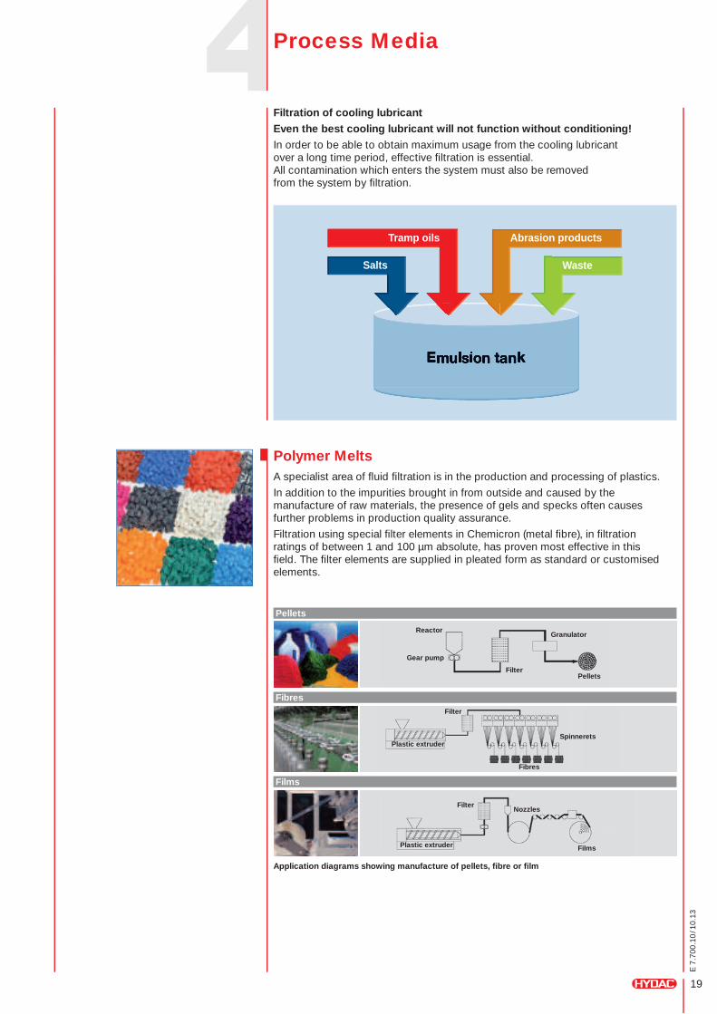
Filtration of cooling lubricantEven the best cooling lubricant will not function without conditioning!In order to be able to obtain maximum usage from the cooling lubricant over a long time period, effective filtration is essential. All contamination which enters the system must also be removed from the system by filtration.
Tramp oils Abrasion products
WasteSalts
Polymer MeltsA specialist area of fluid filtration is in the production and processing of plastics.
In addition to the impurities brought in from outside and caused by the manufacture of raw materials, the presence of gels and specks often causes further problems in production quality assurance.
Filtration using special filter elements in Chemicron (metal fibre), in filtration ratings of between 1 and 100 µm absolute, has proven most effective in this field. The filter elements are supplied in pleated form as standard or customised elements.
Application diagrams showing manufacture of pellets, fibre or film
Pellets
Fibres
Films
Gear pump
Plastic extruder
Plastic extruder
Spinnerets
Nozzles
Films
Fibres
Pellets
ReactorGranulator
Filter
Filter
Filter
Process Media
20
E 7
.700
.10
/10.
13
HydrogenThe European Union has committed itself to converting its transport and energy systems, by 2050, into low-carbon systems and to decoupling economic growth from resource and energy consumption. In combination with a fuel cell, hydrogen can provide a safe energy source which is flexible, decentralized and without emissions. It therefore represents a key technology to achieve these objectives.
Particularly in the automotive industry, hydrogen is gaining increasing importance as an alternative fuel. The cleanliness of the hydrogen is vitally important here for the lifetime of the fuel cell powered vehicles.
Following the launch of the PSA-H70 (HYDAC Accessories), which is a measuring cell for monitoring the H2 cleanl iness on 700 bar hydrogen fuel pumps, remarkably high levels of particle contamination could be detected irrespective of the compressor design or fuel pump manufacturer.
With the gas filter GF1, specially developed by HYDAC Process Technology for hydrogen fuel pumps up to 1,000 bar , it has been possible to draw on the knowledge and experience gained in the dry gas seal filtration sector. All filter elements consist of pleated filter materials which define the filtration rating and the contamination retention capacity and thus fulfil the requirements of hydrogen fuel pumps for the first time.
H2
Process Media
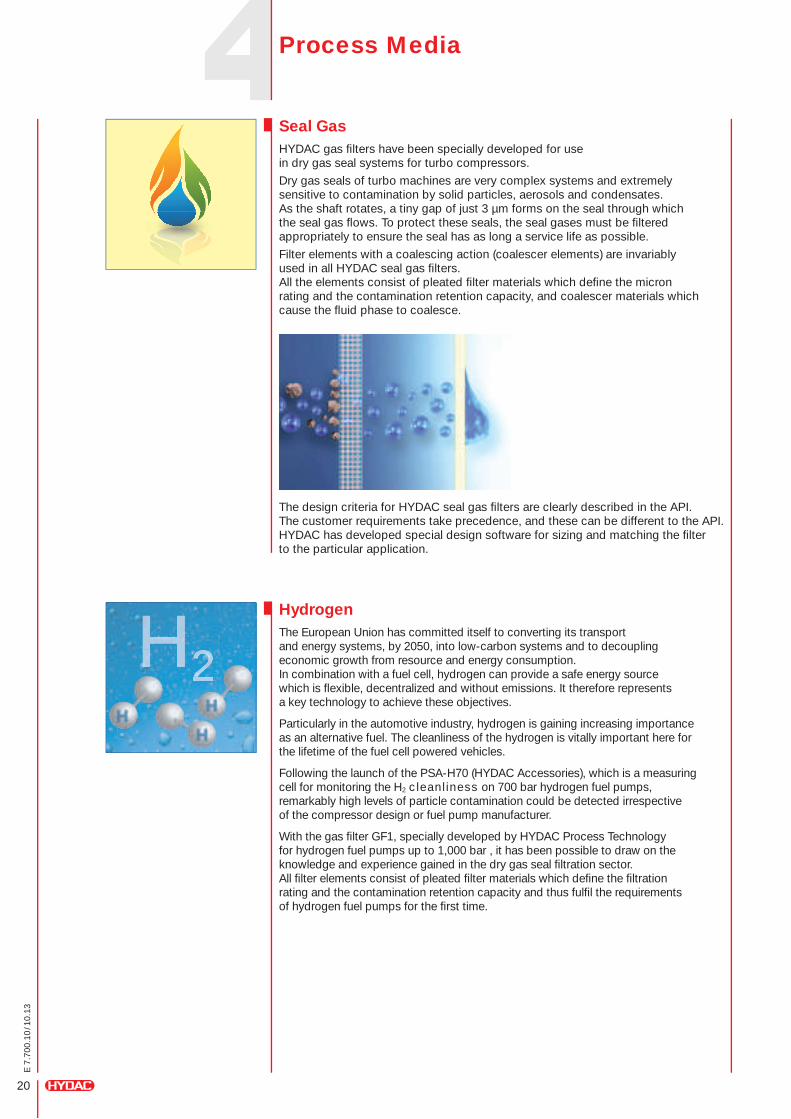
Seal GasHYDAC gas filters have been specially developed for use in dry gas seal systems for turbo compressors.
Dry gas seals of turbo machines are very complex systems and extremely sensitive to contamination by solid particles, aerosols and condensates. As the shaft rotates, a tiny gap of just 3 µm forms on the seal through which the seal gas flows. To protect these seals, the seal gases must be filtered appropriately to ensure the seal has as long a service life as possible.
Filter elements with a coalescing action (coalescer elements) are invariably used in all HYDAC seal gas filters. All the elements consist of pleated filter materials which define the micron rating and the contamination retention capacity, and coalescer materials which cause the fluid phase to coalesce.
The design criteria for HYDAC seal gas filters are clearly described in the API. The customer requirements take precedence, and these can be different to the API. HYDAC has developed special design software for sizing and matching the filter to the particular application.
21
E 7
.700
.10
/10.
13
Type of contamination
Chemicron®
Slotted tube
Medium
Filter material
Particle size [µm]
Wire mesh (Dutch weave)
Fluid group (PED 97/23/EC)
non hazardous/hazardous
Synthetic non- woven material
Wire mesh -–Square mesh
Contamination load (mg/l)
Betamicron®
Particle distribution
Filter bag
Viscosity (cSt.)
Perforated plate
✓✓✓✗✗✗✗✗✗
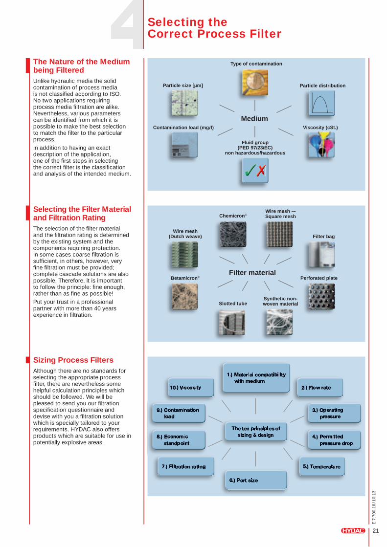
The Nature of the Medium being FilteredUnlike hydraulic media the solid contamination of process media is not classified according to ISO. No two applications requiring process media filtration are alike. Nevertheless, various parameters can be identified from which it is possible to make the best selection to match the filter to the particular process. In addition to having an exact description of the application, one of the first steps in selecting the correct filter is the classification and analysis of the intended medium.
Selecting the Filter Material and Filtration RatingThe selection of the filter material and the filtration rating is determined by the existing system and the components requiring protection. In some cases coarse filtration is sufficient, in others, however, very fine filtration must be provided; complete cascade solutions are also possible. Therefore, it is important to follow the principle: fine enough, rather than as fine as possible!Put your trust in a professional partner with more than 40 years experience in filtration.
Sizing Process FiltersAlthough there are no standards for selecting the appropriate process filter, there are nevertheless some helpful calculation principles which should be followed. We will be pleased to send you our filtration specification questionnaire and devise with you a filtration solution which is specially tailored to your requirements. HYDAC also offers products which are suitable for use in potentially explosive areas.
Selecting the Correct Process Filter
22
E 7
.700
.10
/10.
13
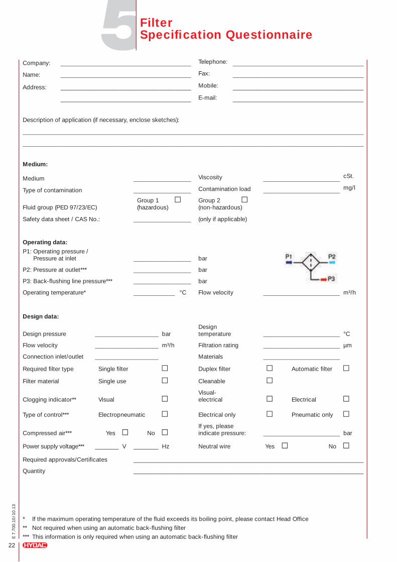
Filter Specification Questionnaire
* If the maximum operating temperature of the fluid exceeds its boiling point, please contact Head Office
** Not required when using an automatic back-flushing filter
*** This information is only required when using an automatic back-flushing filter
Company: Telephone:
Name: Fax:
Address: Mobile:
E-mail:
Description of application (if necessary, enclose sketches):
Medium:
Medium Viscosity cSt.
Type of contamination Contamination load mg/l
Fluid group (PED 97/23/EC)Group 1 (hazardous)
Group 2 (non-hazardous)
Safety data sheet / CAS No.: (only if applicable)
Operating data:
P1: Operating pressure / Pressure at inlet bar
P2: Pressure at outlet*** bar
P3: Back-flushing line pressure*** bar
Operating temperature* °C Flow velocity m³/h
Design data:
Design pressure barDesign temperature °C
Flow velocity m³/h Filtration rating µm
Connection inlet/outlet Materials
Required filter type Single filter Duplex filter Automatic filter
Filter material Single use Cleanable
Clogging indicator** VisualVisual- electrical Electrical
Type of control*** Electropneumatic Electrical only Pneumatic only
Compressed air*** Yes NoIf yes, please indicate pressure: bar
Power supply voltage*** V Hz Neutral wire Yes No
Required approvals/Certificates
Quantity
23
E 7
.700
.10
/10.
13
Customer:
Project:
Which product is to be used?
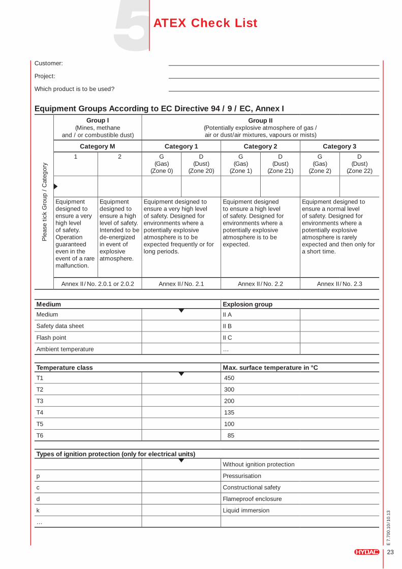
Equipment Groups According to EC Directive 94 / 9 / EC, Annex I
ATEX Check List
Medium Explosion group
Medium II A
Safety data sheet II B
Flash point II C
Ambient temperature …
Temperature class Max. surface temperature in °C
T1 450
T2 300
T3 200
T4 135
T5 100
T6 85
Types of ignition protection (only for electrical units)
Without ignition protection
p Pressurisation
c Constructional safety
d Flameproof enclosure
k Liquid immersion
…
Ple
ase
tick
Gro
up /
Cat
egor
y
Group I(Mines, methane
and / or combustible dust)
Group II(Potentially explosive atmosphere of gas / air or dust/air mixtures, vapours or mists)
Category M Category 1 Category 2 Category 3
1 2 G (Gas)
(Zone 0)
D (Dust)
(Zone 20)
G (Gas)
(Zone 1)
D (Dust)
(Zone 21)
G (Gas)
(Zone 2)
D (Dust)
(Zone 22)
Equipment designed to ensure a very high level of safety. Operation guaranteed even in the event of a rare malfunction.
Equipment designed to ensure a high level of safety. Intended to be de-energized in event of explosive atmosphere.
Equipment designed to ensure a very high level of safety. Designed for environments where a potentially explosive atmosphere is to be expected frequently or for long periods.
Equipment designed to ensure a high level of safety. Designed for environments where a potentially explosive atmosphere is to be expected.
Equipment designed to ensure a normal level of safety. Designed for environments where a potentially explosive atmosphere is rarely expected and then only for a short time.
Annex II / No. 2.0.1 or 2.0.2 Annex II / No. 2.1 Annex II / No. 2.2 Annex II / No. 2.3
Coo
ling
Sys
tem
s 5.
700
Ele
ctro
nics
180
.000
Acc
esso
ries
61.0
00C
omp
act
Hyd
raul
ics
53.0
00Fi
lter
Sys
tem
s 79
.000
Pro
cess
Tec
hnol
ogy
77.0
00Fi
lter
Tech
nolo
gy 7
0.00
0S
pei
cher
tech
nik
30.0
00
E 7
.700
.10
/10.
13
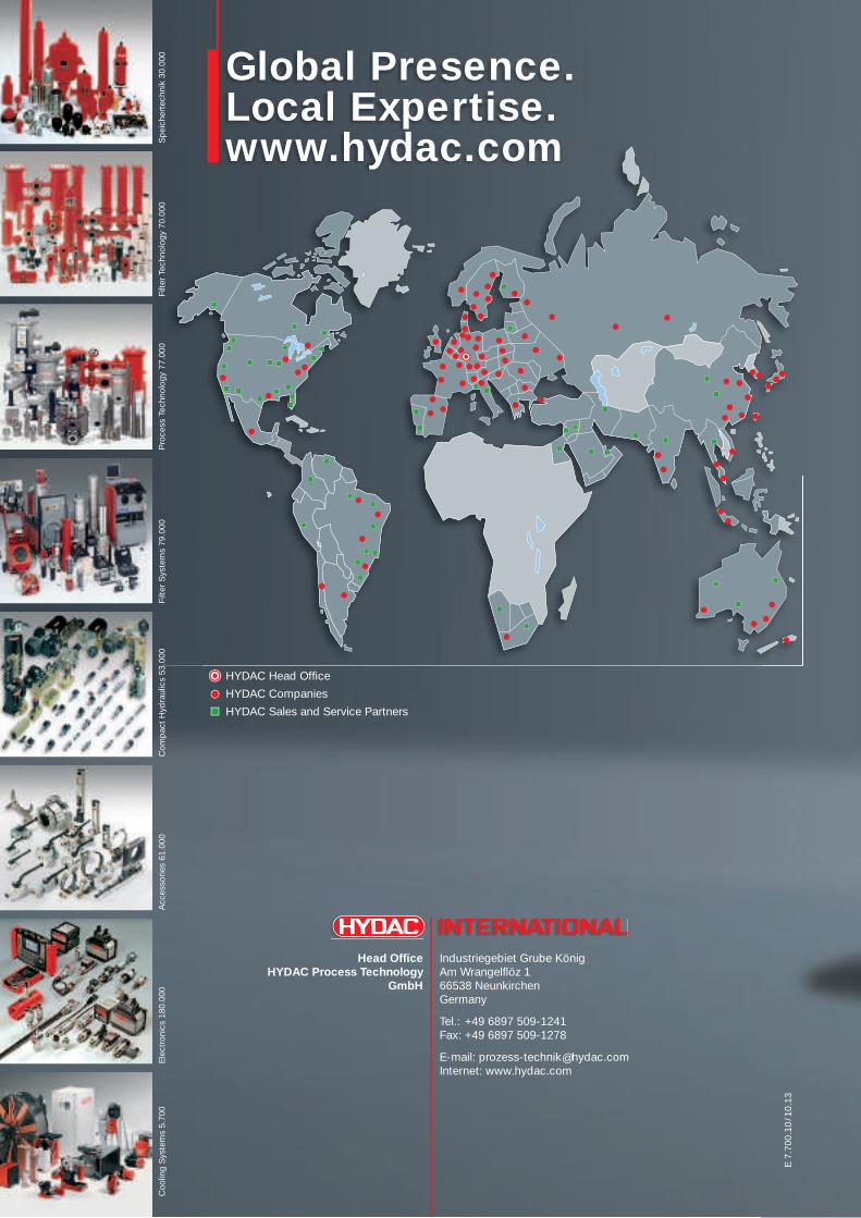
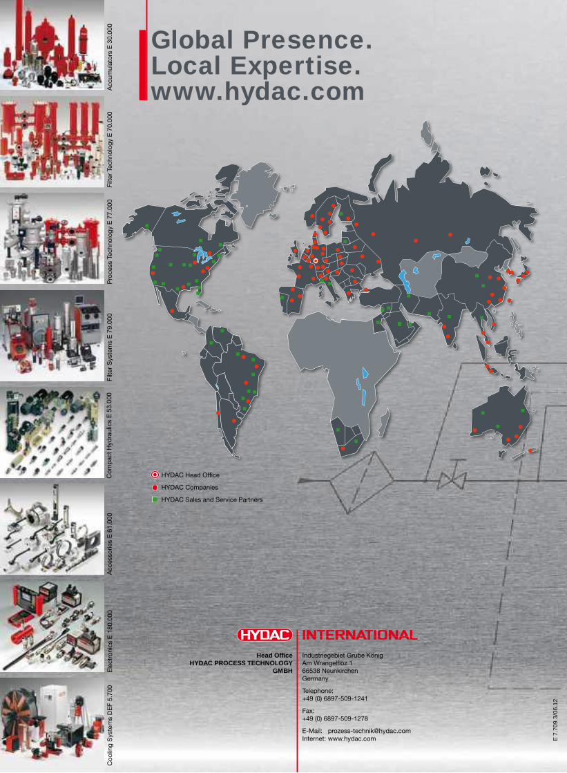
Global Presence.Local Expertise.www.hydac.com
Head Office Industriegebiet Grube König HYDAC Process Technology Am Wrangelflöz 1 GmbH 66538 Neunkirchen Germany
Tel.: +49 6897 509-1241 Fax: +49 6897 509-1278
E-mail: [email protected] Internet: www.hydac.com
HYDAC Head Office
HYDAC Companies
HYDAC Sales and Service Partners

Inline filtersfor process technology.
E 7
.710
.1/0
6.11
2
E 7
.710
.1/0
6.11
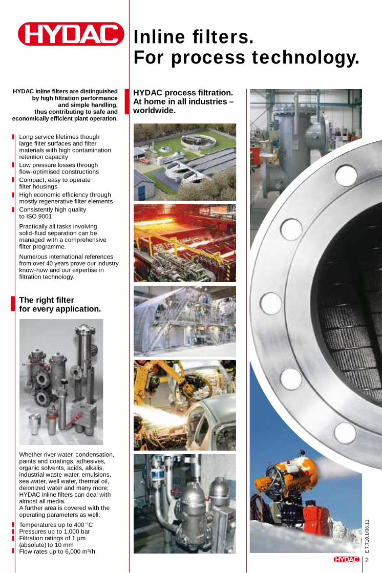
HYDAC process filtration.At home in all industries – worldwide.
Long service lifetimes though large filter surfaces and filter materials with high contamination retention capacityLow pressure losses through flow-optimised constructionsCompact, easy to operate filter housingsHigh economic efficiency through mostly regenerative filter elementsConsistently high quality to ISO 9001
Practically all tasks involving solid-fluid separation can be managed with a comprehensive filter programme.
Numerous international references from over 40 years prove our industry know-how and our expertise in filtration technology.
The right filter for every application.
Whether river water, condensation, paints and coatings, adhesives, organic solvents, acids, alkalis, industrial waste water, emulsions, sea water, well water, thermal oil, deionized water and many more; HYDAC inline filters can deal with almost all media. A further area is covered with the operating parameters as well:
Temperatures up to 400 °CPressures up to 1,000 barFiltration ratings of 1 µm (absolute) to 10 mmFlow rates up to 6,000 m3/h
Inline filters. For process technology.
HYDAC inline filters are distinguished by high filtration performance
and simple handling, thus contributing to safe and
economically efficient plant operation.
3
E 7
.710
.1/0
6.11
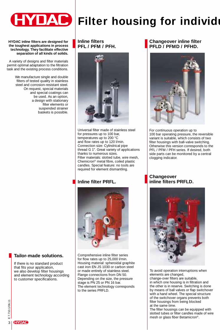
Filter housing for individual requirements.
Inline filters PFL / PFM / PFH.
Universal filter made of stainless steel for pressures up to 100 bar, temperatures up to 200 °C and flow rates up to 120 l/min.Connection size: Cylindrical pipe thread G 1''. Great variety of applications thanks to numerous sizes. Filter materials: slotted tube, wire mesh, Chemicron® metal fibre, coiled plastic candles. Special feature: no tools are required for element dismantling.
Inline filter PRFL.
Comprehensive inline filter series for flow rates up to 25,000 l/min. Housing material: spheroidal graphite cast iron EN JS 1030 or carbon steel or made entirely of stainless steel. Flange connections from DN 50. Depending on the size, the pressure stage is PN 25 or PN 16 bar. The element technology corresponds to the series PRFLD.
Changeover inline filter PFLD / PFMD / PFHD.
For continuous operation up to 100 bar operating pressure, the reversible variant is suitable, which consists of two filter housings with ball-valve switching. Otherwise this version corresponds to the PFL / PFM / PFH series. If desired, both side parts can be monitored by a central clogging indicator.
Changeoverinline filters PRFLD.
To avoid operation interruptions when elements are changed, change-over filters are suitable, in which one housing is in filtration and the other is in reserve. Switching is done by means of ball valves or flap switchover with a hand wheel. The special structure of the switchover organs prevents both filter housings from being blocked at the same time. The filter housings can be equipped with slotted tubes or filter candles made of wire mesh or glass fiber Betamicron®.
Tailor-made solutions.
If there is no standard product that fits your application, we also develop filter housings and element technology according to customer specifications.
HYDAC inline filters are designed for the toughest applications in process technology. They facilitate effective
separation of all kinds of solids.
A variety of designs and filter materials permit optimal adaptation to the filtration task and the existing process conditions.
We manufacture single and double filters of tested quality in stainless
steel and corrosion-resistant steel. On request, special materials
and special coatings can be used. As an option,
a design with stationary filter elements or
suspended strainer baskets is possible.
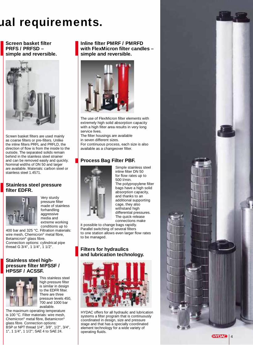
Stainless steel pressure filter EDFR.
Very sturdy pressure filter made of stainless forhandling aggressive media and extreme working conditions up to
400 bar and 325 °C. Filtration materials: wire mesh, Chemicron® metal fibre, Betamicron® glass fibre.Connection options: cylindrical pipe thread G 3/4", 1 1/4", 1 1/2".
Stainless steel high-pressure filter MPSSF / HPSSF / ACSSF.
This stainless steel high pressure filter is similar in design to the EDFR filter. There are three pressure levels 450, 700 and 1000 bar available.
The maximum operating temperature is 100 °C. Filter materials: wire mesh, Chemicron® metal fibre, Betamicron®
glass fibre. Connection options: BSP or NPT thread 1/4", 3/8", 1/2", 3/4", 1", 1 1/4", 1 1/2"; SAE 4 to SAE 24.
Filter housing for individual requirements.
Inline filter PMRF / PMRFD with FlexMicron filter candles – simple and reversible.
The use of FlexMicron filter elements with extremely high solid absorption capacity with a high filter area results in very long service lives. The filter housings are available in seven different sizes. For continuous process, each size is also available as a changeover filter.
Process Bag Filter PBF.Simple stainless steel inline filter DN 50 for flow rates up to 500 l/min. The polypropylene filter bags have a high solid absorption capacity, and thanks to an additional supporting cage, they also withstand high differential pressures. The quick-release connections make
it possible to change bags rapidly. Parallel switching of several filters to one station allows even larger flow rates to be managed.
Filters for hydraulics and lubrication technology.
HYDAC offers for all hydraulic and lubrication systems a filter program that is continuously coordinated in design, size and pressure stage and that has a specially coordinated element technology for a wide variety of operating fluids.
Screen basket filter PRFS / PRFSD – simple and reversible.
Screen basket filters are used mainly as coarse filters or pre-filters. Unlike the inline filters PRFL and PRFLD, the direction of flow is from the inside to the outside. The separated solids remain behind in the stainless steel strainer and can be removed easily and quickly. Nominal widths of DN 50 and larger are available. Materials: carbon steel or stainless steel 1.4571.
4
Filter elements. Elementary and individual.
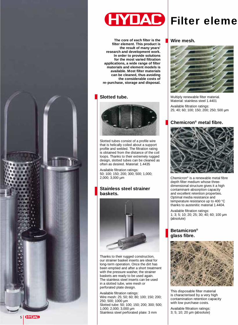
Slotted tube.
Slotted tubes consist of a profile wire that is helically coiled about a support profile and welded. The filtration rating is obtained from the distance of the coil loops. Thanks to their extremely rugged design, slotted tubes can be cleaned as often as desired. Material: 1.4435
Available filtration ratings:50; 100; 150; 200; 300; 500; 1,000; 2,000; 3,000 µm
Stainless steel strainer baskets.
Thanks to their rugged construction, our strainer basket inserts are ideal for long-term operation. Once the dirt has been emptied and after a short treatment with the pressure washer, the strainer baskets are ready to be used again. The stainless steel inserts can be used in a slotted tube, wire mesh or perforated plate design.
Available filtration ratings: Wire mesh: 25; 50; 60; 80; 100; 150; 200; 250; 500; 1000 µm Slotted tube: 50; 100; 150; 200; 300; 500; 1,000; 2,000; 3,000 µm Stainless steel perforated plate: 3 mm
5
The core of each filter is the filter element. This product is
the result of many years' research and development work.
In order to provide solutions for the most varied filtration
applications, a wide range of filter materials and element models is
available. Most filter materials can be cleaned, thus avoiding
the considerable costs of re-purchase, storage and disposal.
Wire mesh.
Betamicron®
glass fibre.
Chemicron® metal fibre.
Multiply renewable filter material. Material: stainless steel 1.4401
Available filtration ratings:25; 40; 60; 100; 150; 200; 250; 500 µm
This disposable filter material is characterised by a very high contamination retention capacity with low purchase costs.
Available filtration ratings: 3; 5; 10; 20 µm (absolute)
Chemicron® is a renewable metal fibre depth filter medium whose three-dimensional structure gives it a high contaminant-absorption capacity and excellent retention properties. Optimal media resistance and temperature resistance up to 400 °C thanks to austenitic material 1.4404.
Available filtration ratings: 1; 3; 5; 10; 20; 25; 30; 40; 60; 100 µm (absolute)
Characterisation of the filtration performance.
In order to compare the different filter materials, the degree of separation ßx was defined in the filter technology. This value describes the quantitative proportion of particles above a certain grain size, before and after the filter element.
ßx =
X = Particle size in µm
Absolute filtration rating – for Betamicron® glass fibre, coiled candles and Chemicron® metal fibre
A ßx value of 100 (ßx = 100) corresponds to a degree of separation of 99%. A test filter must retain at least 99% of the particles above the specified filtration rating, up to the specified differential pressure. This is referred to as absolute filtration.
The values specified in the brochure are determined by the multi-pass test (for the determination and proof of the filtration performance, extended to finest filtration) carried out on the HYDAC test rig, based on ISO 4572.
Nominal filtration rating– for wire mesh and slotted tubes
No ßx values are set for this. The mesh or gap width of the corresponding filter material are specified as the filtration rating.
Number of particles > x µm in the inflowNumber of particles > x µm in the filtrate
Filter elements. Elementary and individual.
6
E 7
.710
.1/0
6.11
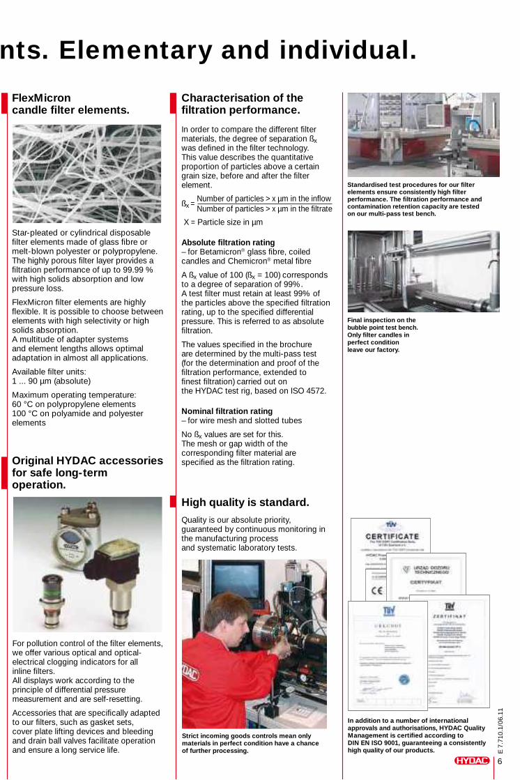
FlexMicron candle filter elements.
Original HYDAC accessoriesfor safe long-term operation.
Star-pleated or cylindrical disposable filter elements made of glass fibre or melt-blown polyester or polypropylene. The highly porous filter layer provides a filtration performance of up to 99.99 % with high solids absorption and low pressure loss.
FlexMicron filter elements are highly flexible. It is possible to choose between elements with high selectivity or high solids absorption. A multitude of adapter systems and element lengths allows optimal adaptation in almost all applications.
Available filter units:1 ... 90 µm (absolute)
Maximum operating temperature:60 °C on polypropylene elements 100 °C on polyamide and polyester elements
For pollution control of the filter elements, we offer various optical and optical-electrical clogging indicators for all inline filters. All displays work according to the principle of differential pressure measurement and are self-resetting.
Accessories that are specifically adapted to our filters, such as gasket sets, cover plate lifting devices and bleeding and drain ball valves facilitate operation and ensure a long service life.
Strict incoming goods controls mean only materials in perfect condition have a chance of further processing.
In addition to a number of international approvals and authorisations, HYDAC Quality Management is certified according to DIN EN ISO 9001, guaranteeing a consistently high quality of our products.
Final inspection on the bubble point test bench. Only filter candles in perfect condition leave our factory.
Standardised test procedures for our filter elements ensure consistently high filter performance. The filtration performance and contamination retention capacity are tested on our multi-pass test bench.
High quality is standard.
Quality is our absolute priority, guaranteed by continuous monitoring in the manufacturing process and systematic laboratory tests.
7
E 7
.710
.1/0
6.11
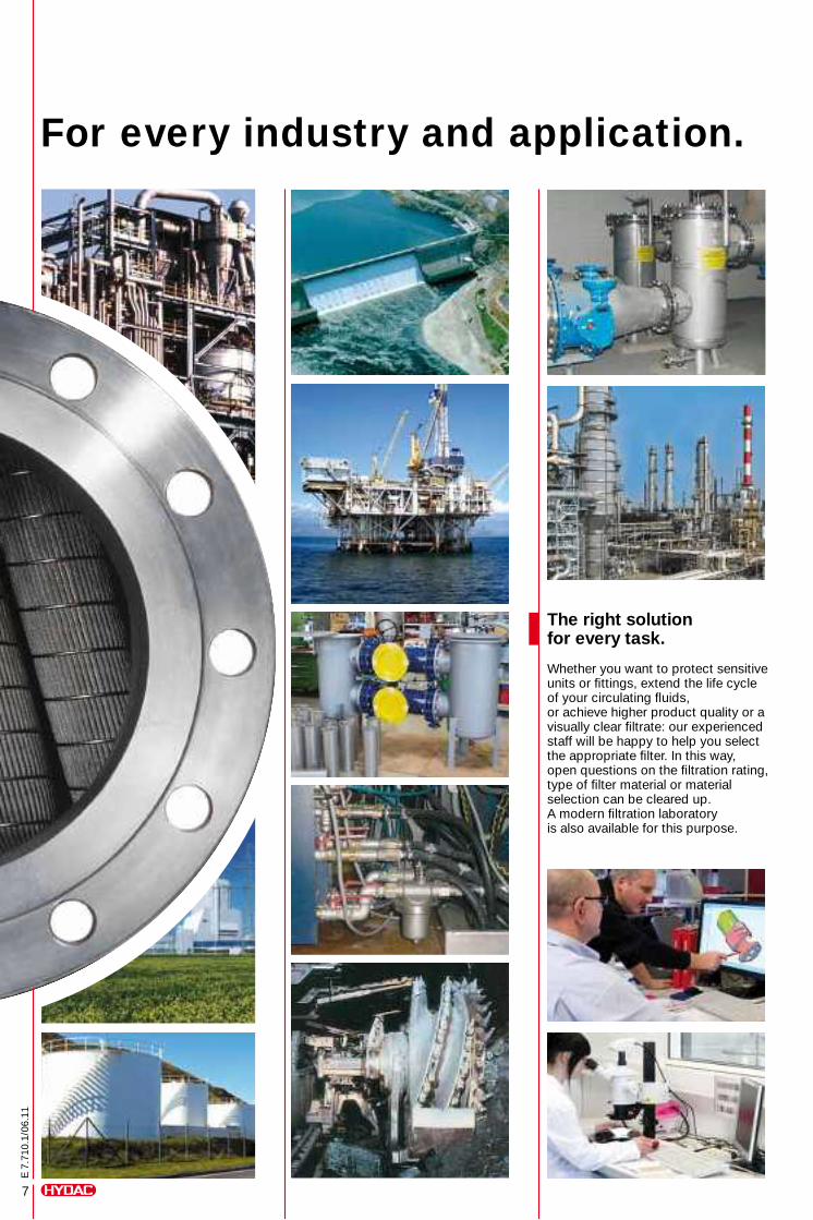
For every industry and application.
The right solution for every task.
Whether you want to protect sensitive units or fittings, extend the life cycle of your circulating fluids, or achieve higher product quality or a visually clear filtrate: our experienced staff will be happy to help you select the appropriate filter. In this way, open questions on the filtration rating, type of filter material or material selection can be cleared up. A modern filtration laboratory is also available for this purpose.

E 7
.710
.1/0
6.11

Automatic Back-Flushing Filter for Process Technology AutoFilt® RF3.
E 7
.709
.3/0
6.12
AutoFilt® RF3: So automatic,
2
E 7
.709
.3/0
6.12
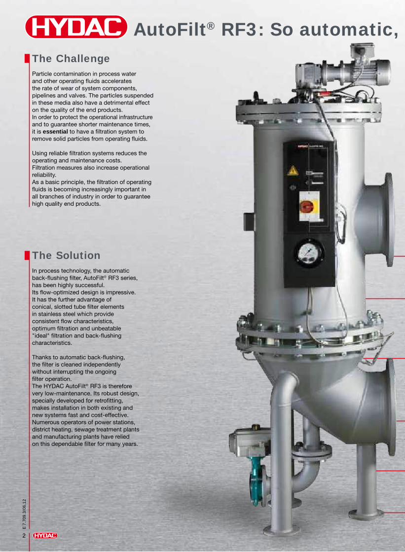
The ChallengeParticle contamination in process water and other operating fluids accelerates the rate of wear of system components, pipelines and valves. The particles suspended in these media also have a detrimental effect on the quality of the end products. In order to protect the operational infrastructure and to guarantee shorter maintenance times, it is essential to have a filtration system to remove solid particles from operating fluids. Using reliable filtration systems reduces the operating and maintenance costs. Filtration measures also increase operational reliability. As a basic principle, the filtration of operating fluids is becoming increasingly important in all branches of industry in order to guarantee high quality end products.
The SolutionIn process technology, the automatic back-flushing filter, AutoFilt® RF3 series, has been highly successful. Its flow-optimized design is impressive. It has the further advantage of conical, slotted tube filter elements in stainless steel which provide consistent flow characteristics, optimum filtration and unbeatable "ideal" filtration and back-flushing characteristics. Thanks to automatic back-flushing, the filter is cleaned independently without interrupting the ongoing filter operation. The HYDAC AutoFilt® RF3 is therefore very low-maintenance. Its robust design, specially developed for retrofitting, makes installation in both existing and new systems fast and cost-effective. Numerous operators of power stations, district heating, sewage treatment plants and manufacturing plants have relied on this dependable filter for many years.

7
E 7
.709
.3/0
6.12
Isokinetic filtration and back-flushing• Maximum utilization of the filter area• Full filtration performance after back-flushing• Complete cleaning of the conical filter elements
Variable housing configuration• Reduced costs due to simple and space-saving installation• Simple to install
Easy to service• Low maintenance requirement• Low operating costs
Fully automatic operation• Highly reliable• User intervention not required• Low operating costs• Individually adjustable control parameters
Ready-to-operate unit• All components (control, differential pressure gauge, back-flushing valve, gear motor) are already installed on the filter, ready to use• Once the pipework has been connected, all that is required is for the auxiliary power supply to be applied
Applications• Removal of solid particles from low-viscosity fluids
• Can be used in almost all sectors of industry
Industries and ApplicationsThe diverse range of applications makes the HYDAC AutoFilt® RF3 ideal for use in numerous sectors of industry:
you might forget it's there.
Power industry
• Conditioning of industrial water used to cool generators
• Filtration of sealing water to increase the service life of the turbine shaft floating ring seals in hydroelectric power stations
Mining
• Filtration of water for shield spraying
• Filtration of water for coal-cutting machinery
• Treatment of cooling water for mine ventilation
Automotive industry• Filtration of coolant lubricants
• Filtration of washing fluids
• Protection of machine tools
Water / waste water conditioning
• Protective filter before membrane systems
• Conditioning of service water in sewage treatment plants
Steel industry• Filtration of process water to protect nozzles and pumps in high pressure descaling
• Water conditioning for cooling blast furnaces and rolling mills
• Emulsion filtration in hot and cold rolling mills
• Filtration of rolling emulsions
Chemical industry • Cooling water filtration
• Waste water filtration
• Filtration of chemicals
Oil and gas industry • Filtration of injection water
• Filtration of cooling water
• Filtration of service water
• Filtration of flushing water (pipeline flushing)
• Filtration solution for the subsea sector
Paper industry
• Protection of all types of nozzles on paper machines
• Treatment of fresh water (e.g. river water) to be used for cooling
Marine
• Pre-filtration for ballast water conditioning systems

SuperMesh wire mesh
Slotted tube
3
E 7
.709
.3/0
6.12
Isokinetic filtration and back-flushingThe special conical shape and configuration of the filter elements allow consistent flow, resulting in a low pressure drop and complete cleaning of the elements.
Advantages:Fewer back-flushing cyclesLower back-flushing losses
Efficiency of back-flushingFilter elements:Cylindrical vs. Conical
Choice of filter materials
Function model
Performance enhanced by Isokinetics.
Material: stainless steel
Filtration rating: 25 µm – ≤ 60 µm
Material: stainless steel
Filtration rating: 50 µm – 3 mm
low high
Back-flushingFiltration
5
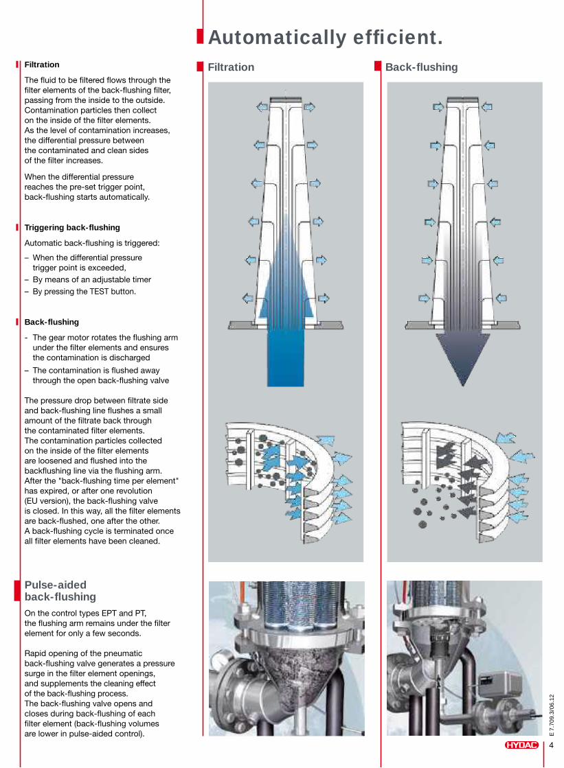
Filtration
The fluid to be filtered flows through the filter elements of the back-flushing filter, passing from the inside to the outside. Contamination particles then collect on the inside of the filter elements. As the level of contamination increases, the differential pressure between the contaminated and clean sides of the filter increases.
When the differential pressure reaches the pre-set trigger point, back-flushing starts automatically.
Triggering back-flushing
Automatic back-flushing is triggered:
– When the differential pressure trigger point is exceeded,– By means of an adjustable timer– By pressing the TEST button.
Back-flushing
- The gear motor rotates the flushing arm under the filter elements and ensures the contamination is discharged
– The contamination is flushed away through the open back-flushing valve
The pressure drop between filtrate side and back-flushing line flushes a small amount of the filtrate back through the contaminated filter elements. The contamination particles collected on the inside of the filter elements are loosened and flushed into the backflushing line via the flushing arm. After the "back-flushing time per element" has expired, or after one revolution (EU version), the back-flushing valve is closed. In this way, all the filter elements are back-flushed, one after the other. A back-flushing cycle is terminated once all filter elements have been cleaned.
Pulse-aided back-flushingOn the control types EPT and PT, the flushing arm remains under the filter element for only a few seconds.
Rapid opening of the pneumatic back-flushing valve generates a pressure surge in the filter element openings, and supplements the cleaning effect of the back-flushing process. The back-flushing valve opens and closes during back-flushing of each filter element (back-flushing volumes are lower in pulse-aided control).
Back-flushingFiltration
Automatically efficient.
4
E 7
.709
.3/0
6.12
Performance enhanced by Isokinetics.
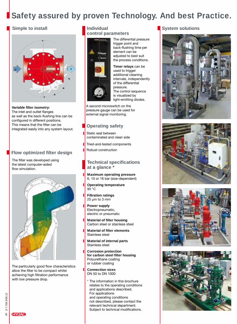
Technical specifications at a glance *
Maximum operating pressure6, 10 or 16 bar (size-dependent)
Operating temperature 90 °C
Filtration ratings 25 µm to 3 mm
Power supply Electropneumatic, electric or pneumatic
Material of filter housing Carbon steel or stainless steel
Material of filter elementsStainless steel
Material of internal parts Stainless steel
Corrosion protectionfor carbon steel filter housing Polyurethane coating or rubber coating
Connection sizes DN 50 to DN 1000
* The information in this brochure relates to the operating conditions and applications described. For applications and operating conditions not described, please contact the relevant technical department. Subject to technical modifications.
The differential pressure trigger point and back-flushing time per element can be adjusted to best suit the process conditions.
Timer relays can be used to trigger additional cleaning intervals, independently of the differential pressure. The control sequence is visualized by light-emitting diodes.
A second microswitch on the pressure gauge can be used for external signal monitoring.
Individual control parameters
5
E 7
.709
.3/0
6.12
System solutionsSimple to install
Flow optimized filter design
Variable filter isometry: The inlet and outlet flanges as well as the back-flushing line can be configured in different positions. This means that the filter can be integrated easily into any system layout.
The particularly good flow characteristics allow the filter to be compact whilst achieving high filtration performance with low pressure drop.
The filter was developed using the latest computer-aided flow simulation.
4
Safety assured by proven Technology. And best Practice.
Operating safety
Static seal between contaminated and clean side
Tried-and-tested components
Robust construction
6
E 7
.709
.3/0
6.12
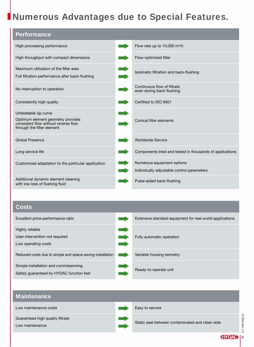
Performance
High processing performance Flow rate up to 10,000 m3/h
High throughput with compact dimensions Flow-optimized filter
Maximum utilization of the filter area
Full filtration performance after back-flushingIsokinetic filtration and back-flushing
No interruption to operationContinuous flow of filtrate even during back-flushing
Consistently high quality Certified to ISO 9001
Unbeatable ∆p curve
Optimum element geometry provides consistent flow without reverse flow through the filter element
Conical filter elements
Global Presence Worldwide Service
Long service life Components tried and tested in thousands of applications
Customized adaptation to the particular application Numerous equipment options
Individually adjustable control parameters
Additional dynamic element cleaning with low loss of flushing fluid
Pulse-aided back-flushing
Costs
Excellent price-performance ratio Extensive standard equipment for real-world applications
Highly reliable
User intervention not required
Low operating costs
Fully automatic operation
Reduced costs due to simple and space-saving installation Variable housing isometry
Simple installation and commissioning
Safety guaranteed by HYDAC function testReady-to-operate unit
Numerous Advantages due to Special Features.
Maintenance
Low maintenance costs Easy to service
Guaranteed high quality filtrate
Low maintenanceStatic seal between contaminated and clean side
Industriegebiet Grube KönigAm Wrangelflöz 166538 NeunkirchenGermany
Telephone: +49 (0) 6897-509-1241
Fax:+49 (0) 6897-509-1278
E-Mail: [email protected] Internet: www.hydac.com
Head OfficeHYDAC PROCESS TECHNOLOGY
GMBH
E 7
.709
.3/0
6.12
Global Presence. Local Expertise. www.hydac.com
HYDAC Head Office
HYDAC Companies
HYDAC Sales and Service Partners
Pro
cess
Tec
hnol
ogy
E 7
7.00
0Fi
lter
Sys
tem
s E
79.
000
Com
pac
t H
ydra
ulic
s E
53.
000
Acc
esso
ries
E 6
1.00
0E
lect
roni
cs E
180
.000
Coo
ling
Sys
tem
s D
EF
5.70
0Fi
lter
Tech
nolo
gy E
70.
000
Acc
umul
ator
s E
30.
000
E 7
.711
.2/0
6.12
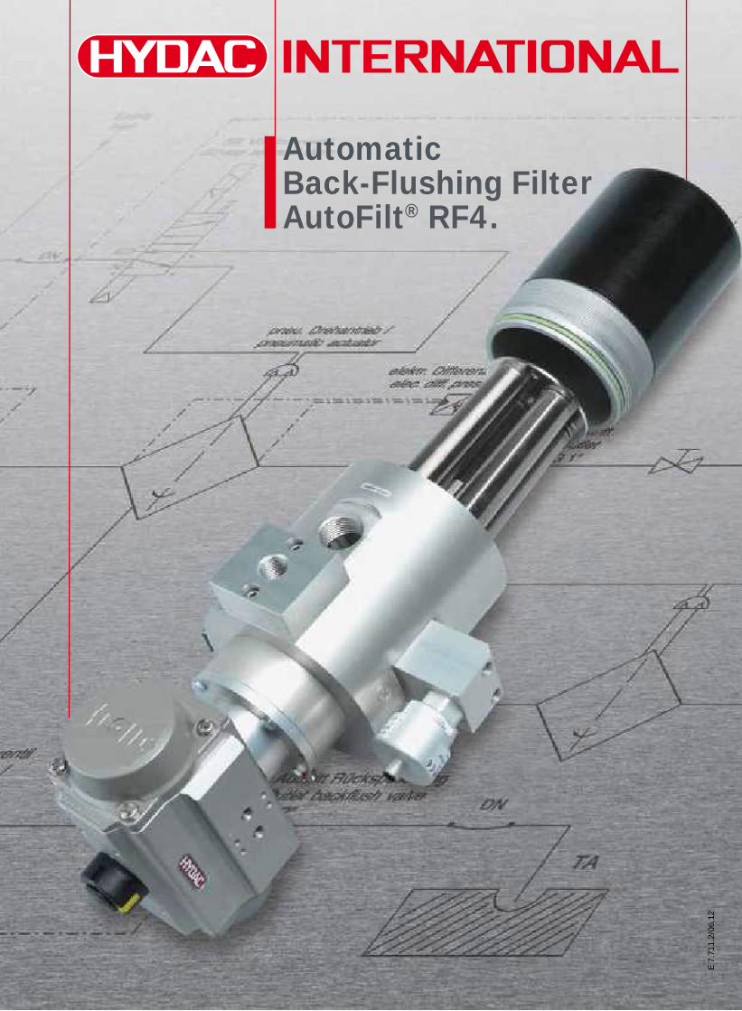
AutomaticBack-Flushing Filter AutoFilt® RF4.
2
E 7
.711
.2/0
6.12
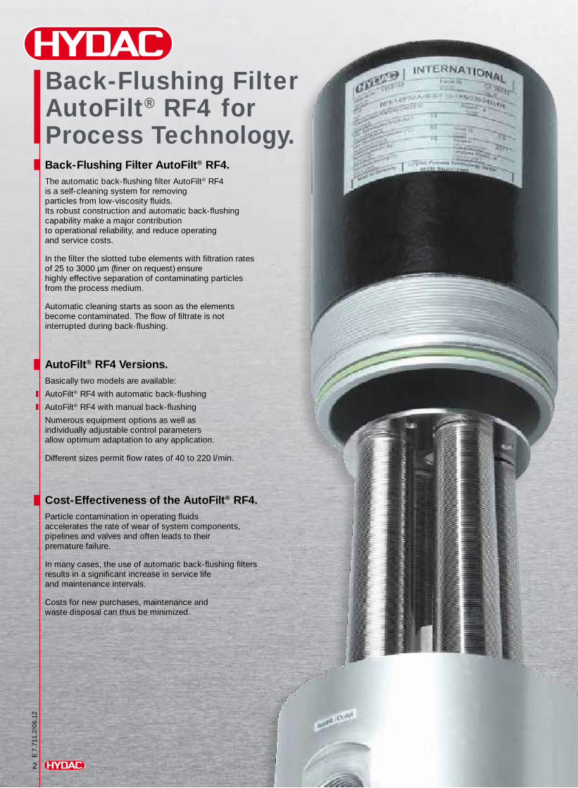
Back-Flushing Filter AutoFilt® RF4. The automatic back-flushing filter AutoFilt® RF4 is a self-cleaning system for removing particles from low-viscosity fluids. Its robust construction and automatic back-flushing capability make a major contribution to operational reliability, and reduce operating and service costs.
In the filter the slotted tube elements with filtration rates of 25 to 3000 μm (finer on request) ensure highly effective separation of contaminating particles from the process medium.
Automatic cleaning starts as soon as the elements become contaminated. The flow of filtrate is not interrupted during back-flushing.
AutoFilt® RF4 Versions.Basically two models are available:
AutoFilt® RF4 with automatic back-flushing
AutoFilt® RF4 with manual back-flushing
Numerous equipment options as well as individually adjustable control parameters allow optimum adaptation to any application.
Different sizes permit flow rates of 40 to 220 l/min.
Cost-Effectiveness of the AutoFilt® RF4.Particle contamination in operating fluids accelerates the rate of wear of system components, pipelines and valves and often leads to their premature failure.
In many cases, the use of automatic back-flushing filters results in a significant increase in service life and maintenance intervals.
Costs for new purchases, maintenance and waste disposal can thus be minimized.
Back-Flushing FilterAutoFilt® RF4 for Process Technology.
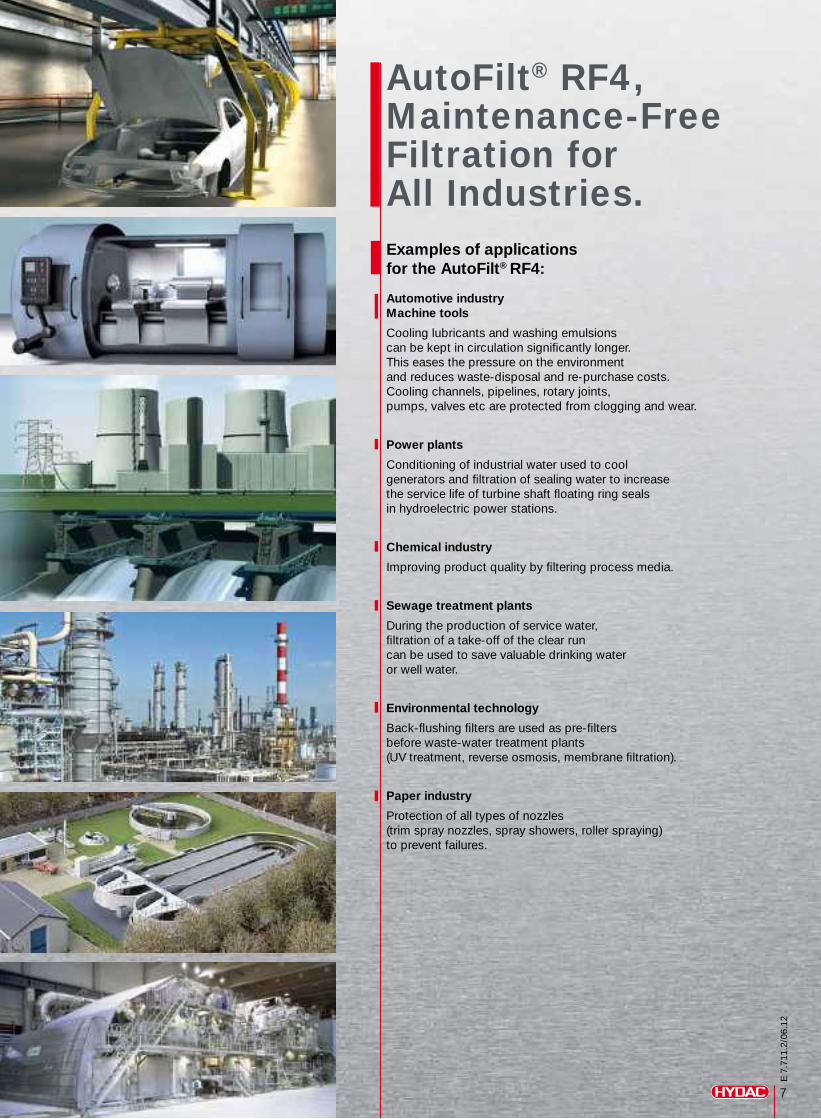
Examples of applications for the AutoFilt® RF4: Automotive industryMachine tools
Cooling lubricants and washing emulsions can be kept in circulation significantly longer.This eases the pressure on the environment and reduces waste-disposal and re-purchase costs. Cooling channels, pipelines, rotary joints, pumps, valves etc are protected from clogging and wear.
Power plants
Conditioning of industrial water used to cool generators and filtration of sealing water to increase the service life of turbine shaft floating ring seals in hydroelectric power stations.
Chemical industry
Improving product quality by filtering process media.
Sewage treatment plants
During the production of service water, filtration of a take-off of the clear run can be used to save valuable drinking water or well water.
Environmental technology
Back-flushing filters are used as pre-filters before waste-water treatment plants (UV treatment, reverse osmosis, membrane filtration).
Paper industry
Protection of all types of nozzles (trim spray nozzles, spray showers, roller spraying) to prevent failures.
7
E 7
.711
.2/0
6.12
AutoFilt® RF4, Maintenance-Free Filtration for All Industries.
3
E 7
.711
.2/0
6.12
Back-Flushing AutoFilt® RF4 for Continuous Filtration. Special Features of the AutoFilt® RF4.
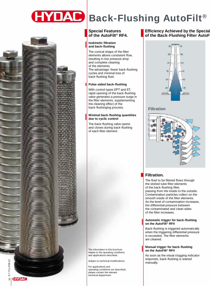
Isokinetic filtration and back-flushing
The conical shape of the filter elements allows consistent flow, resulting in low pressure drop and complete cleaning of the elements. The advantage: fewer back-flushing cycles and minimal loss of back-flushing fluid.
Pulse-aided back-flushing
With control types EPT and ET, rapid opening of the back-flushing valve generates a pressure surge in the filter elements, supplementing the cleaning effect of the back-flushinging process.
Minimal back-flushing quantities due to cyclic control
The back-flushing valve opens and closes during back-flushing of each filter element.
Filtration.The fluid to be filtered flows through the slotted tube filter elements of the back-flushing filter, passing from the inside to the outside.Contamination particles collect on the smooth inside of the filter elements.As the level of contamination increases, the differential pressure between the contaminated and clean sides of the filter increases.
Automatic trigger for back-flushing on the AutoFilt® RF4
Back-flushing is triggered automatically when the triggering differential pressure is exceeded. The filter elements are cleaned.
Manual trigger for back-flushing on the AutoFilt® RF4
As soon as the visual clogging indicator responds, back-flushing is started manually.
The information in this brochure relates to the operating conditions and applications described.
Subject to technical modifications.
For applications and operating conditions not described, please contact the relevant technical department.
Efficiency Achieved by the Special Flow-Enhancing Design of the Back-Flushing Filter AutoFilt® RF4.
Filtration
4
Back-Flushing AutoFilt® RF4 for Continuous Filtration.
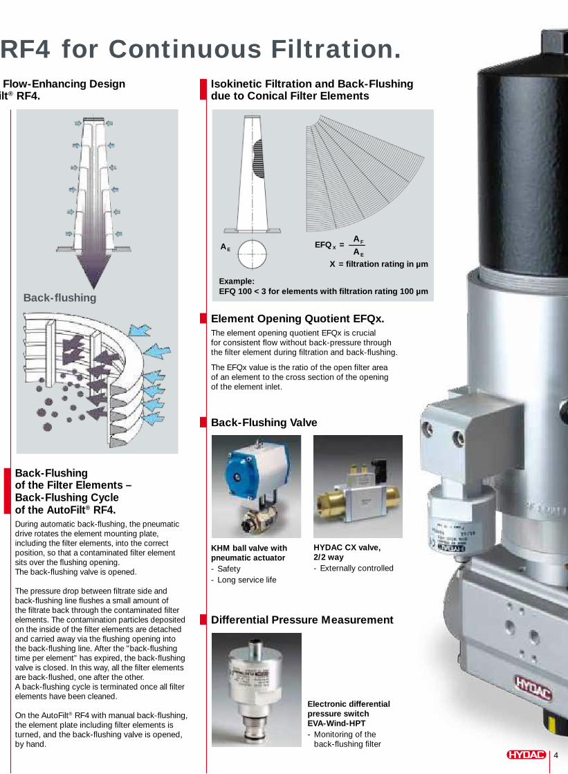
Back-Flushing of the Filter Elements – Back-Flushing Cycle of the AutoFilt® RF4.During automatic back-flushing, the pneumatic drive rotates the element mounting plate, including the filter elements, into the correct position, so that a contaminated filter element sits over the flushing opening. The back-flushing valve is opened.
The pressure drop between filtrate side and back-flushing line flushes a small amount of the filtrate back through the contaminated filter elements. The contamination particles deposited on the inside of the filter elements are detached and carried away via the flushing opening into the back-flushing line. After the "back-flushing time per element" has expired, the back-flushing valve is closed. In this way, all the filter elements are back-flushed, one after the other. A back-flushing cycle is terminated once all filter elements have been cleaned.
On the AutoFilt® RF4 with manual back-flushing, the element plate including filter elements is turned, and the back-flushing valve is opened, by hand.
Element Opening Quotient EFQx.The element opening quotient EFQx is crucial for consistent flow without back-pressure through the filter element during filtration and back-flushing.
The EFQx value is the ratio of the open filter area of an element to the cross section of the opening of the element inlet.
Back-Flushing Valve
KHM ball valve with pneumatic actuator- Safety- Long service life
Differential Pressure Measurement
Electronic differential pressure switch EVA-Wind-HPT- Monitoring of the back-flushing filter
HYDAC CX valve, 2/2 way- Externally controlled
Efficiency Achieved by the Special Flow-Enhancing Design of the Back-Flushing Filter AutoFilt® RF4.
Isokinetic Filtration and Back-Flushing due to Conical Filter Elements
Back-flushing
A EA FA E
EFQ X = –
X = filtration rating in µm
Example:EFQ 100 < 3 for elements with filtration rating 100 µm
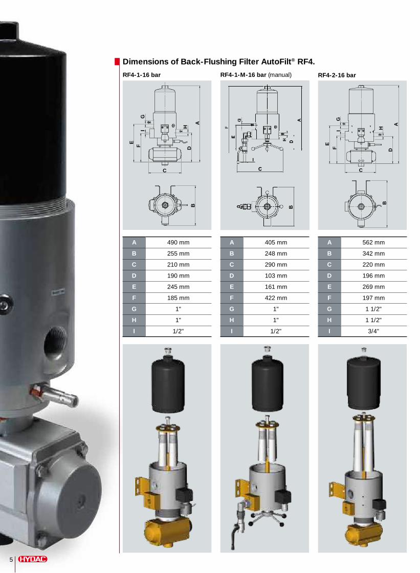
Dimensions of Back-Flushing Filter AutoFilt® RF4.
RF4-1-16 bar RF4-1-M-16 bar (manual) RF4-2-16 bar
A 490 mm
B 255 mm
C 210 mm
D 190 mm
E 245 mm
F 185 mm
G 1"
H 1"
I 1/2"
A 405 mm
B 248 mm
C 290 mm
D 103 mm
E 161 mm
F 422 mm
G 1"
H 1"
I 1/2"
A 562 mm
B 342 mm
C 220 mm
D 196 mm
E 269 mm
F 197 mm
G 1 1/2"
H 1 1/2"
I 3/4"
5
B
G
A
D
C
E
H
FI
B
G
AD
C
E
H
FI
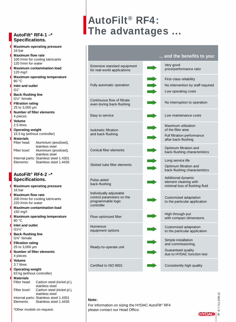
Extensive standard equipment for real-world applications
Very goodprice/performance ratio
Fully automatic operation
First-class reliability
No intervention by staff required
Low operating costs
Continuous flow of filtrate even during back-flushing No interruption to operation
Easy to service Low maintenance costs
Isokinetic filtration and back-flushing
Maximum utilization of the filter area
Full filtration performanceafter back-flushing
Conical filter elementsOptimum filtration and back-flushing characteristics
Slotted tube filter elementsLong service life
Optimum filtration and back-flushing characteristics
Pulse-aided back-flushing
Additional dynamicelement cleaning with minimal loss of flushing fluid
Individually adjustable control parameters on theprogrammable logic controller
Customized adaptation to the particular application
Flow-optimized filterHigh through-put with compact dimensions
Numerousequipment options
Customized adaptationto the particular application
Ready-to-operate unit
Simple installation and commissioning,
Guaranteed quality due to HYDAC function test
Certified to ISO 9001 Consistently high quality
AutoFilt® RF4: The advantages ...
6
E 7
.711
.2/0
6.12
AutoFilt® RF4-1 –* Specifications.Maximum operating pressure16 barMaximum flow rate100 l/min for cooling lubricants120 l/min for waterMaximum contamination load120 mg/lMaximum operating temperature80 °CInlet and outletG1"Back-flushing lineG½" femaleFiltration rating25 to 3,000 μmNumber of filter elements4 piecesVolume2.5 litres Operating weight15.5 kg (without controller)MaterialsFilter head: Aluminium (anodized), stainless steelFilter bowl: Aluminium (anodized), stainless steelInternal parts: Stainless steel 1.4301Elements: Stainless steel 1.4435
AutoFilt® RF4-2 –* Specifications.Maximum operating pressure16 barMaximum flow rate200 l/min for cooling lubricants220 l/min for waterMaximum contamination load150 mg/lMaximum operating temperature80 °CInlet and outletG1½"Back-flushing lineG¾" femaleFiltration rating25 to 3,000 μmNumber of filter elements4 piecesVolume3.7 litres Operating weight63 kg (without controller)MaterialsFilter head: Carbon steel (nickel pl.), stainless steelFilter bowl: Carbon steel (nickel pl.), stainless steelInternal parts: Stainless steel 1.4301Elements: Stainless steel 1.4435
*Other models on request.
Note:For information on sizing the HYDAC AutoFilt® RF4 please contact our Head Office.
... and the benefits to you:
E 7
.711
.2/0
6.12
Global Presence.Local Expertise.www.hydac.com
HYDAC Headquarters
HYDAC Companies
HYDAC Sales and Service Partners
Industriegebiet Grube KönigAm Wrangelflöz 166538 NeunkirchenGermany
Telephone: +49 6897 509-1241
Fax: +49 6897 509-1278
Internet: www.hydac.comE-Mail: [email protected]
HYDAC PROCESS TECHNOLOGY GMBH
Pro
cess
Tec
hnol
ogy
E 7
7.00
0Fi
lter
Sys
tem
s E
79.
000
Com
pac
t H
ydra
ulic
s E
53.
000
Acc
esso
ries
E 6
1.00
0E
lect
roni
cs E
180
.000
Coo
ling
Sys
tem
s D
EF
5.70
0Fi
lter
Tech
nolo
gy E
70.
000
Acc
umul
ator
s E
30.
000
E 7
.810
.0/0
6.12
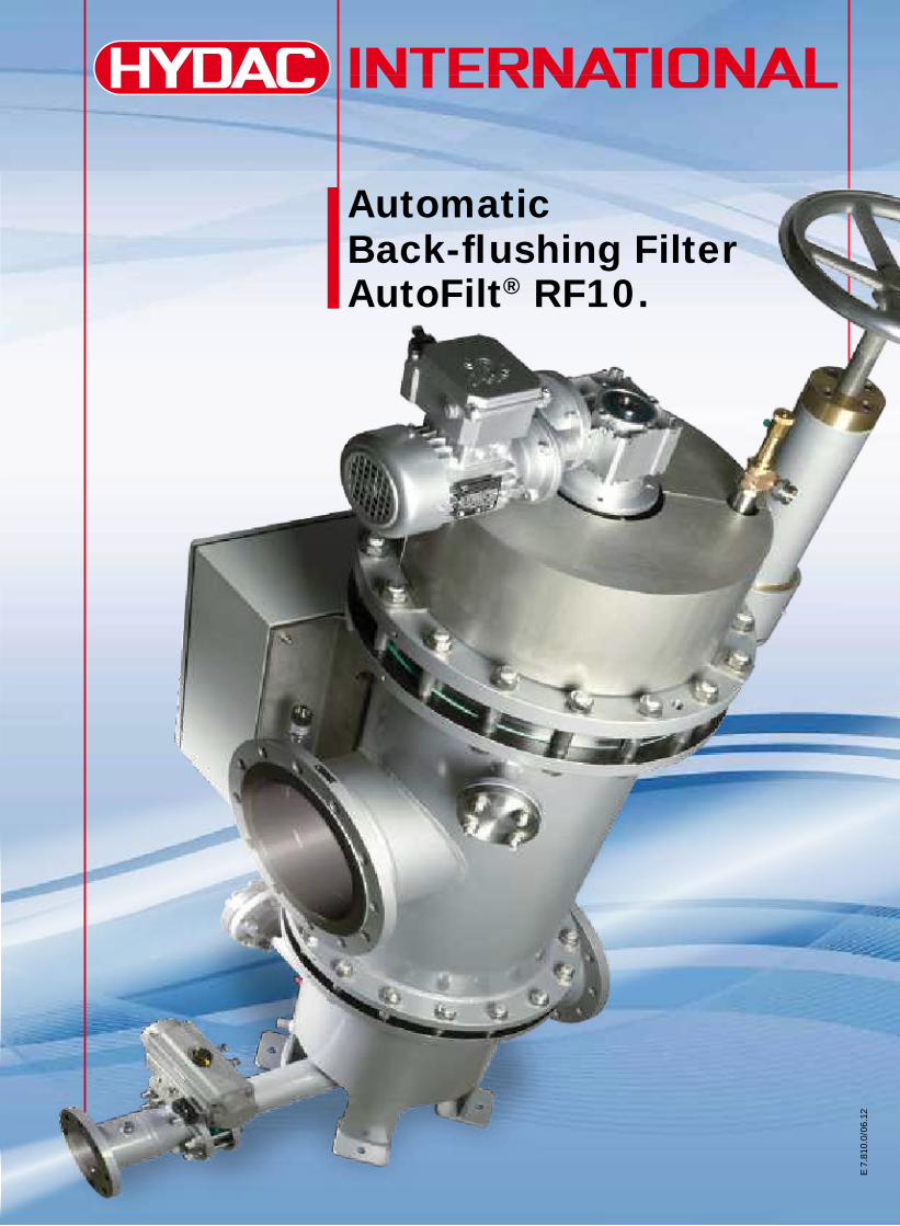
Automatic Back-flushing FilterAutoFilt® RF10.
New paths in filtration – AutoFilt® RF10.
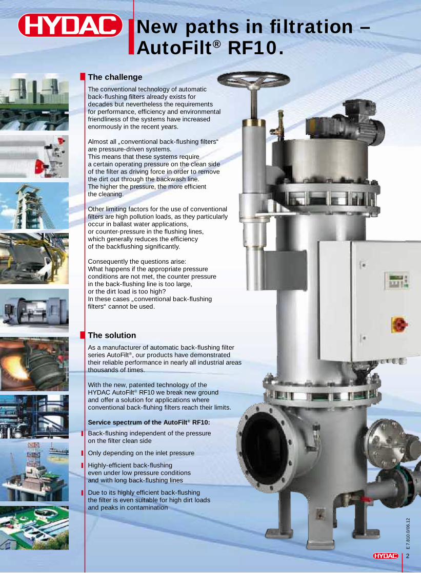
The challengeThe conventional technology of automatic back-flushing filters already exists for decades but nevertheless the requirements for performance, efficiency and environmental friendliness of the systems have increased enormously in the recent years.
Almost all „conventional back-flushing filters“ are pressure-driven systems.This means that these systems require a certain operating pressure on the clean sideof the filter as driving force in order to remove the dirt out through the backwash line. The higher the pressure, the more efficient the cleaning.
Other limiting factors for the use of conventional filters are high pollution loads, as they particularly occur in ballast water applications, or counter-pressure in the flushing lines,which generally reduces the efficiency of the backflushing significantly.
Consequently the questions arise: What happens if the appropriate pressure conditions are not met, the counter pressure in the back-flushing line is too large, or the dirt load is too high? In these cases „conventional back-flushing filters“ cannot be used.
The solution As a manufacturer of automatic back-flushing filter series AutoFilt®, our products have demonstrated their reliable performance in nearly all industrial areas thousands of times.
With the new, patented technology of the HYDAC AutoFilt® RF10 we break new ground and offer a solution for applications where conventional back-fluhing filters reach their limits.
Service spectrum of the AutoFilt® RF10:
Back-flushing independent of the pressure on the filter clean side
Only depending on the inlet pressure
Highly-efficient back-flushing even under low pressure conditions and with long back-flushing lines
Due to its highly efficient back-flushing the filter is even suitable for high dirt loadsand peaks in contamination
2
E 7
.810
.0/0
6.12
AutoFilt® RF10 – element technology at the highest level.
3
E 7
.810
.0/0
6.12
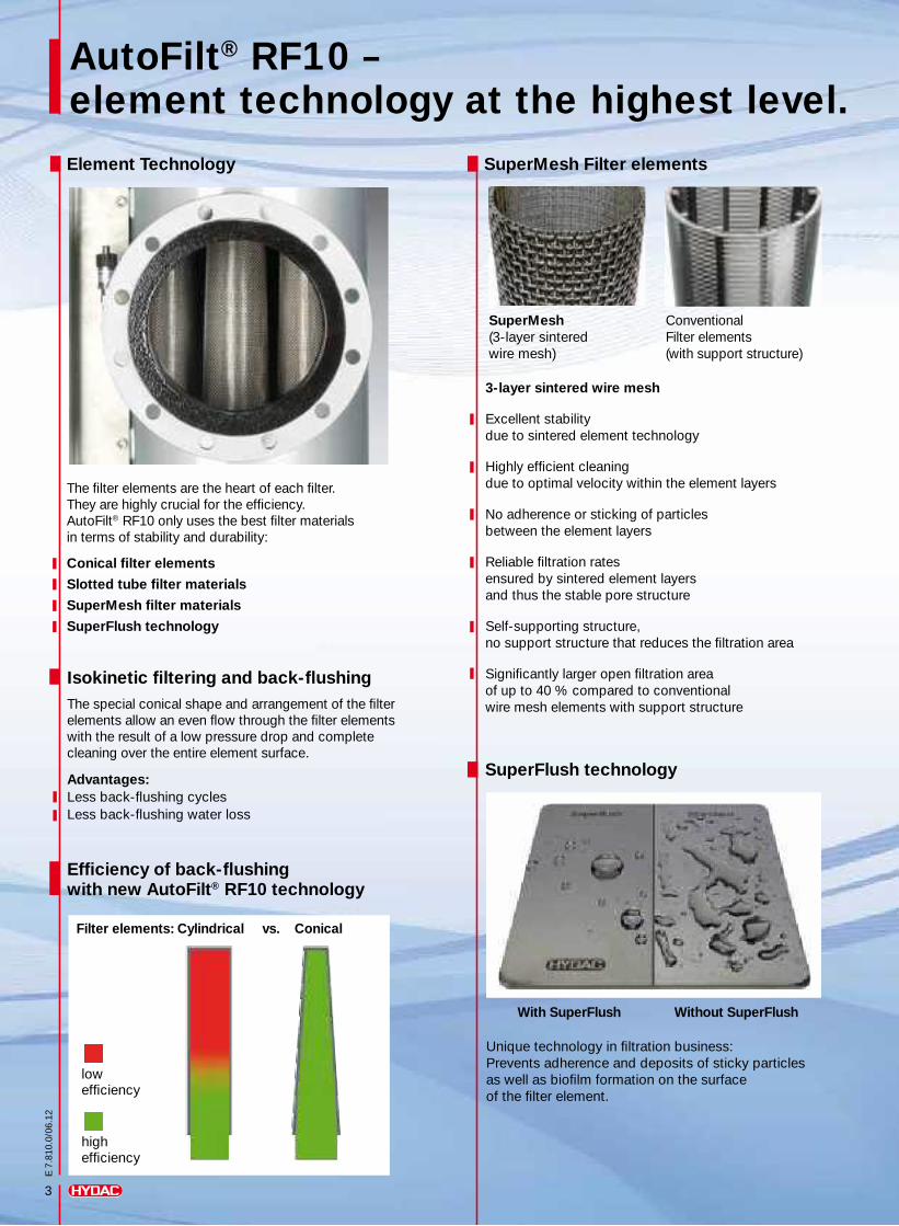
Element Technology SuperMesh Filter elements
The filter elements are the heart of each filter. They are highly crucial for the efficiency. AutoFilt® RF10 only uses the best filter materials in terms of stability and durability:
Conical filter elements
Slotted tube filter materials
SuperMesh filter materials
SuperFlush technology
3-layer sintered wire mesh
Excellent stability due to sintered element technology
Highly efficient cleaning due to optimal velocity within the element layers
No adherence or sticking of particles between the element layers
Reliable filtration rates ensured by sintered element layers and thus the stable pore structure
Self-supporting structure, no support structure that reduces the filtration area
Significantly larger open filtration area of up to 40 % compared to conventional wire mesh elements with support structure
Conventional Filter elements (with support structure)
SuperFlush technology
Unique technology in filtration business: Prevents adherence and deposits of sticky particles as well as biofilm formation on the surface of the filter element.
With SuperFlush Without SuperFlush
SuperMesh (3-layer sintered wire mesh)
lowefficiency
highefficiency
Efficiency of back-flushing with new AutoFilt® RF10 technology
Isokinetic filtering and back-flushingThe special conical shape and arrangement of the filter elements allow an even flow through the filter elements with the result of a low pressure drop and complete cleaning over the entire element surface.
Advantages: Less back-flushing cyclesLess back-flushing water loss
Filter elements: Cylindrical vs. Conical
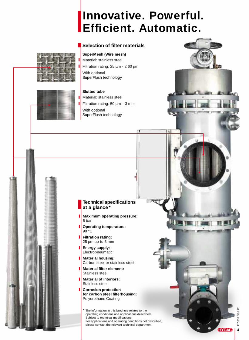
Innovative. Powerful. Efficient. Automatic. Selection of filter materials
SuperMesh (Wire mesh) Material: stainless steel
Filtration rating: 25 µm - ≤ 60 µm
With optional SuperFlush technology
Slotted tube Material: stainless steel
Filtration rating: 50 µm – 3 mm
With optional SuperFlush technology
Technical specifications at a glance *
Maximum operating pressure: 6 bar
Operating temperature: 90 °C
Filtration rating: 25 µm up to 3 mm
Energy supply: Electropneumatic
Material housing: Carbon steel or stainless steel
Material filter element: Stainless steel
Material of interiors: Stainless steel
Corrosion protection for carbon steel filterhousing: Polyurethane Coating
* The information in this brochure relates to the operating conditions and applications described. Subject to technical modifications. For applications and operating conditions not described, please contact the relevant technical department.
4
E 7
.810
.0/0
6.12
5
E 7
.810
.0/0
6.12
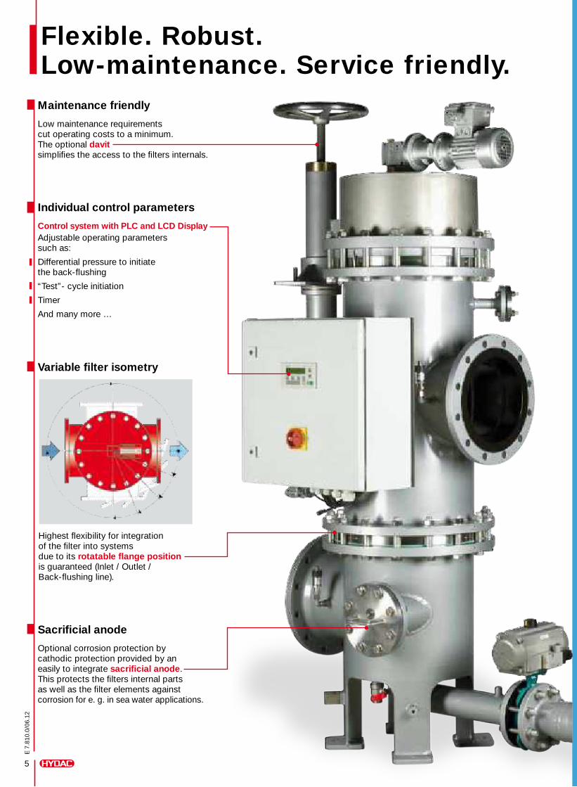
Flexible. Robust. Low-maintenance. Service friendly.
Maintenance friendly Low maintenance requirements cut operating costs to a minimum. The optional davit simplifies the access to the filters internals.
Sacrificial anode Optional corrosion protection by cathodic protection provided by an easily to integrate sacrificial anode. This protects the filters internal parts as well as the filter elements against corrosion for e. g. in sea water applications.
Variable filter isometry
Highest flexibility for integration of the filter into systems due to its rotatable flange position is guaranteed (Inlet / Outlet / Back-flushing line).
Individual control parameters Control system with PLC and LCD Display Adjustable operating parameters such as:
Differential pressure to initiate the back-flushing
“Test”- cycle initiation
Timer
And many more …
Industriegebiet Grube KönigAm Wrangelflöz 166538 NeunkirchenGermany
Telephone: +49 6897 509-1241
Fax: +49 6897 509-1278
E-Mail: [email protected] Internet: www.hydac.com
Head OfficeHYDAC PROCESS TECHNOLOGY
GMBH
E 7
.810
.0/0
6.12
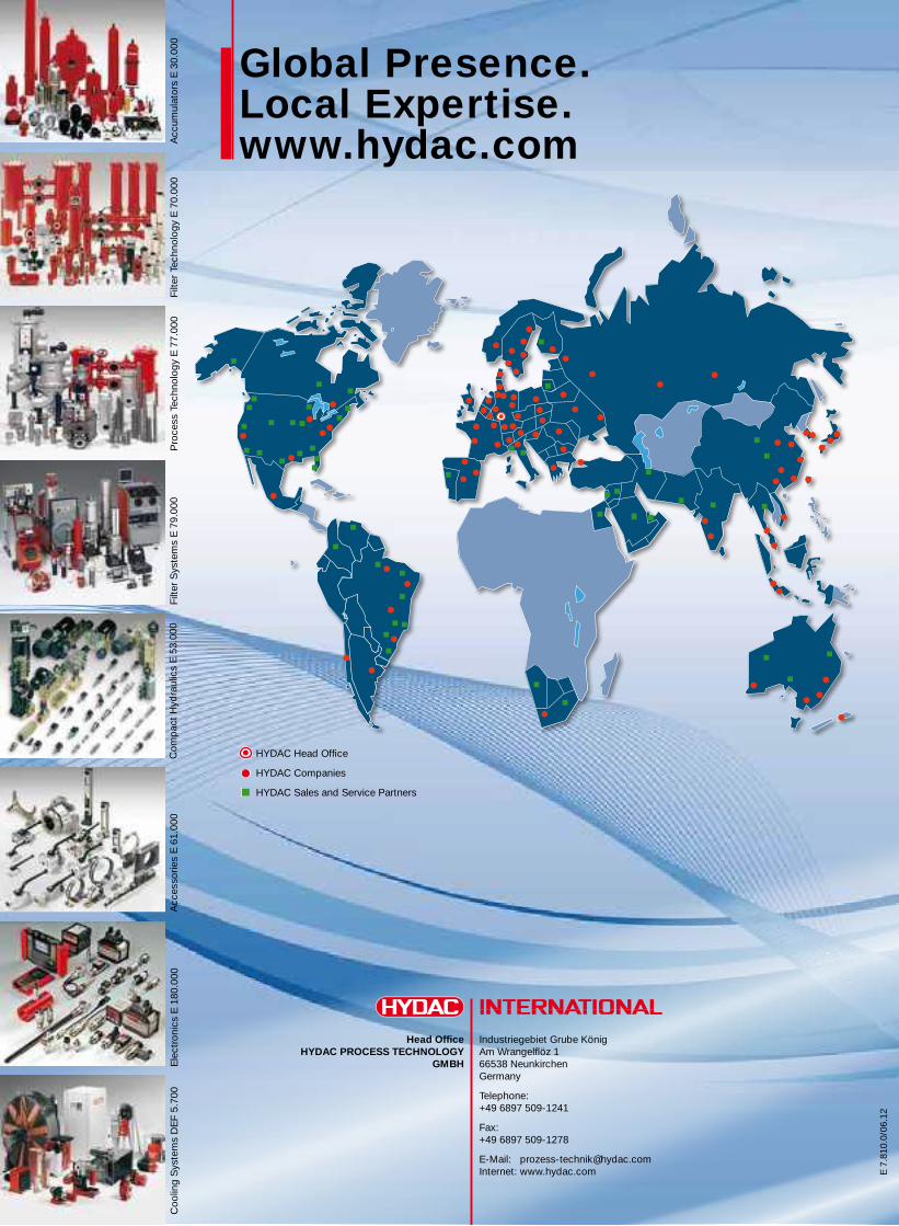
Global Presence. Local Expertise. www.hydac.com
HYDAC Head Office
HYDAC Companies
HYDAC Sales and Service Partners
Pro
cess
Tec
hnol
ogy
E 7
7.00
0Fi
lter
Sys
tem
s E
79.
000
Com
pac
t H
ydra
ulic
s E
53.
000
Acc
esso
ries
E 6
1.00
0E
lect
roni
cs E
180
.000
Coo
ling
Sys
tem
s D
EF
5.70
0Fi
lter
Tech
nolo
gy E
70.
000
Acc
umul
ator
s E
30.
000
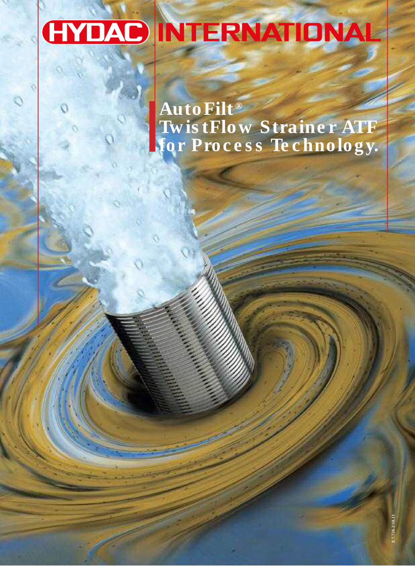
AutoFilt®TwistFlow Strainer ATFfor Process Technology.
E7.
726.
2/10
.11
E7.
726.
2/10
.11
2
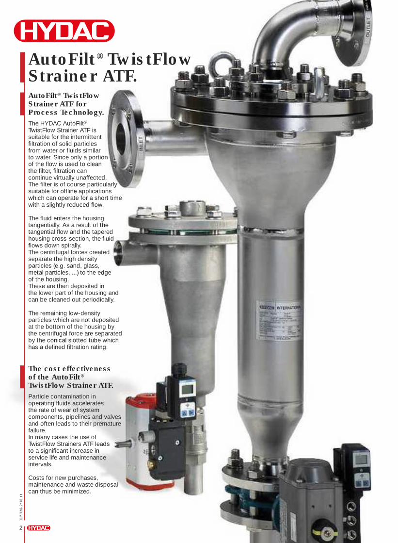
AutoFilt® TwistFlowStrainer ATF.AutoFilt® TwistFlowStrainer ATF forProcess Technology.The HYDAC AutoFilt®TwistFlow Strainer ATF issuitable for the intermittentfiltration of solid particlesfrom water or fluids similarto water. Since only a portionof the flow is used to cleanthe filter, filtration cancontinue virtually unaffected.The filter is of course particularlysuitable for offline applicationswhich can operate for a short timewith a slightly reduced flow.
The fluid enters the housingtangentially. As a result of thetangential flow and the taperedhousing cross-section, the fluidflows down spirally.The centrifugal forces createdseparate the high densityparticles (e.g. sand, glass,metal particles, ...) to the edgeof the housing.These are then deposited inthe lower part of the housing andcan be cleaned out periodically.
The remaining low-densityparticles which are not depositedat the bottom of the housing bythe centrifugal force are separatedby the conical slotted tube whichhas a defined filtration rating.
The cost effectivenessof the AutoFilt®TwistFlow Strainer ATF.Particle contamination inoperating fluids acceleratesthe rate of wear of systemcomponents, pipelines and valvesand often leads to their prematurefailure.In many cases the use ofTwistFlow Strainers ATF leadsto a significant increase inservice life and maintenanceintervals.
Costs for new purchases,maintenance and waste disposalcan thus be minimized.
E7.
726.
2/10
.11
7
Application examples fromautomotive industry to environmental technology.
TwistFlow Strainers ATF are usedas pre-filters before wastetreatment plants (UV treatment,reverse osmosis, membranefiltration ...).
Hydroelectric power plants
Treatment of industrial waterfor cooling generators and filtrationof sealing water to increasethe service life of the turbineshaft floating ring sealsin hydroelectric power stations.
Automotive industry
Filtering the cooling and servicewater protects cooling channelsand pipelines from clogging.
Alpine technology
Filtration of water for protectionof snow cannons and snow lancesto ensure the snow quality.
Chemical industry
Environmental technology
Improving product qualityby filtering process media.
Steel industry
Paper industry
Protection of nozzles and pumpsduring high-pressure descaling,water treatment for cooling blastfurnaces and rolling mills
For example: the protectionof spray nozzles for the screensof paper machines. This resultsin fewer failures causedby clogging and wear.
Sewage treatment plants
During the production of servicewater, filtration of a take-offof the clear run can be usedto save valuable drinking wateror well water.
Special featuresof the AutoFilt®TwistFlow Strainer ATF.In order to ensure that processand service water is producedreliably from surface water,the separation process usedto treat the water must copewith vigorous fluctuations inthe quality of the untreated water.
For conventional filters,these surges in concentrationoften cause a considerablereduction in performance,and even system downtime,and as a result a reductionin their cost-effectivenessor operating reliability as well.
This problem has led to thedevelopment of a new, patentedfilter for solid-liquid separationto cope with these vigorousfluctuations in concentration,a filter which at the same timealways guarantees consistentquality of the filtrate – irrespectiveof fluctuations in the operatingpressure or flow rate.
With filtration ratings ofbetween 200 and 3,000 µm,the AutoFilt® TwistFlowStrainer ATF is particularlysuited to the separation ofsolid particles in suspensionup to several grams per litrefrom preferably water-basedor low-viscosity fluids.
Areas of applicationof the AutoFilt®TwistFlow Strainer ATF.The TwistFlow Strainer ATFis suitable for separating solidparticles from low-viscosity fluidsand is used, for example, as a:
Pre-filterbefore AutoFilt® RF3 / RF4
Pre-filterto relieve sand filters
Pre-filterbefore membrane systems
Surface water filter
Seawater filter
Process water filter
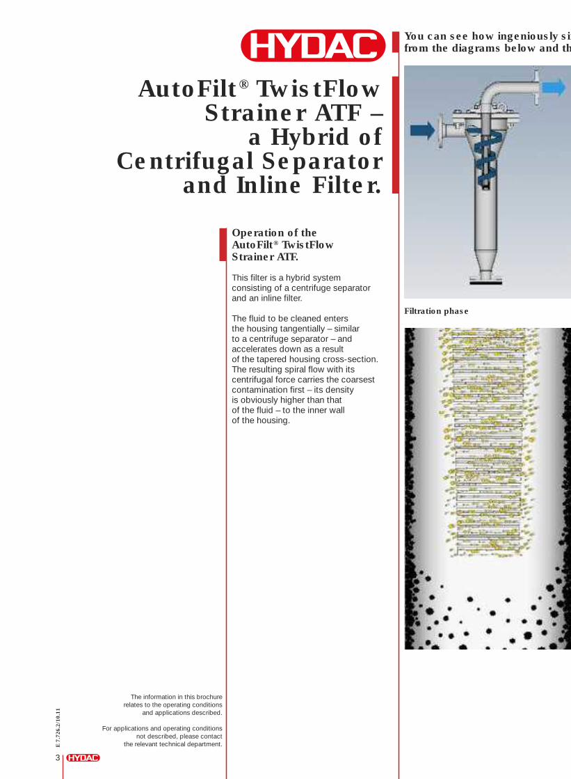
Operation of theAutoFilt® TwistFlowStrainer ATF.
This filter is a hybrid systemconsisting of a centrifuge separatorand an inline filter.
The fluid to be cleaned entersthe housing tangentially – similarto a centrifuge separator – andaccelerates down as a resultof the tapered housing cross-section.The resulting spiral flow with itscentrifugal force carries the coarsestcontamination first – its densityis obviously higher than thatof the fluid – to the inner wallof the housing.
Filtration phase
AutoFilt® TwistFlowStrainer ATF –
a Hybrid ofCentrifugal Separator
and Inline Filter.
The information in this brochurerelates to the operating conditions
and applications described.
For applications and operating conditionsnot described, please contact
the relevant technical department.
You can see how ingeniously simfrom the diagrams below and th
E7.
726.
2/10
.11
3
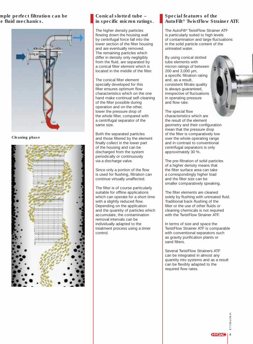
Conical slotted tube –in specific micron ratings.
The higher density particlesflowing down the housing wallby centrifugal force fall into thelower section of the filter housingand are eventually removed.The remaining particles whichdiffer in density only negligiblyfrom the fluid, are separated bya conical filter element which islocated in the middle of the filter.
The conical filter elementspecially developed for thisfilter ensures optimum flowcharacteristics which on the onehand make continual self-cleaningof the filter possible duringoperation and on the other,lower the pressure drop ofthe whole filter, compared witha centrifugal separator of thesame size.
Both the separated particlesand those filtered by the elementfinally collect in the lower partof the housing and can bedischarged from the systemperiodically or continuouslyvia a discharge valve.
Since only a portion of the flowis used for flushing, filtration cancontinue virtually unaffected.
The filter is of course particularlysuitable for offline applicationswhich can operate for a short timewith a slightly reduced flow.Depending on the applicationand the quantity of particles whichaccumulate, the contaminationremoval intervals can beindividually adapted to thetreatment process using a timercontrol.
Cleaning phase
E7.
726.
2/10
.11
4
Special features of theAutoFilt® TwistFlow Strainer ATF.
The AutoFilt® TwistFlow Strainer ATFis particularly suited to high levelsof contamination and large fluctuationsin the solid particle content of theuntreated water.
By using conical slottedtube elements withmicron ratings of between200 and 3,000 µm,a specific filtration ratingand, as a result,consistent filtrate qualityis always guaranteed,irrespective of fluctuationsin operating pressureand flow rate.
The special flowcharacteristics which arethe result of the elementgeometry and their configurationmean that the pressure dropof the filter is comparatively lowover the whole operating rangeand in contrast to conventionalcentrifugal separators is onlyapproximately 30 %.
The pre-filtration of solid particlesof a higher density means thatthe filter surface area can takea correspondingly higher loadand the filter size can besmaller comparatively speaking.
The filter elements are cleanedsolely by flushing with untreated fluid.Traditional back-flushing of thefilter or the use of other fluids orcleaning chemicals is not requiredwith the TwistFlow Strainer ATF.
In terms of size and space theTwistFlow Strainer ATF is comparablewith conventional separators suchas gravity purification plants orsand filters.
Several TwistFlow Strainers ATFcan be integrated in almost anyquantity into systems and as a resultcan be flexibly adapted to therequired flow rates.
mple perfect filtration can behe fluid mechanics.
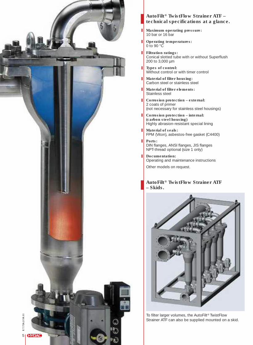
E7.
726.
2/10
.11
5
AutoFilt® TwistFlow Strainer ATF– Skids.
To filter larger volumes, the AutoFilt® TwistFlowStrainer ATF can also be supplied mounted on a skid.
AutoFilt® TwistFlow Strainer ATF –technical specifications at a glance.
Maximum operating pressure:10 bar or 16 bar
Operating temperatures:0 to 90 °C
Filtration ratings:Conical slotted tube with or without Superflush200 to 3,000 µm
Types of control:Without control or with timer control
Material of filter housing:Carbon steel or stainless steel
Material of filter elements:Stainless steel
Corrosion protection – external:2 coats of primer(not necessary for stainless steel housings)
Corrosion protection – internal:(carbon steel housing)Highly abrasion-resistant special lining
Material of seals:FPM (Viton), asbestos-free gasket (C4400)
Ports:DIN flanges, ANSI flanges, JIS flangesNPT-thread optional (size 1 only)
Documentation:Operating and maintenance instructions
Other models on request.
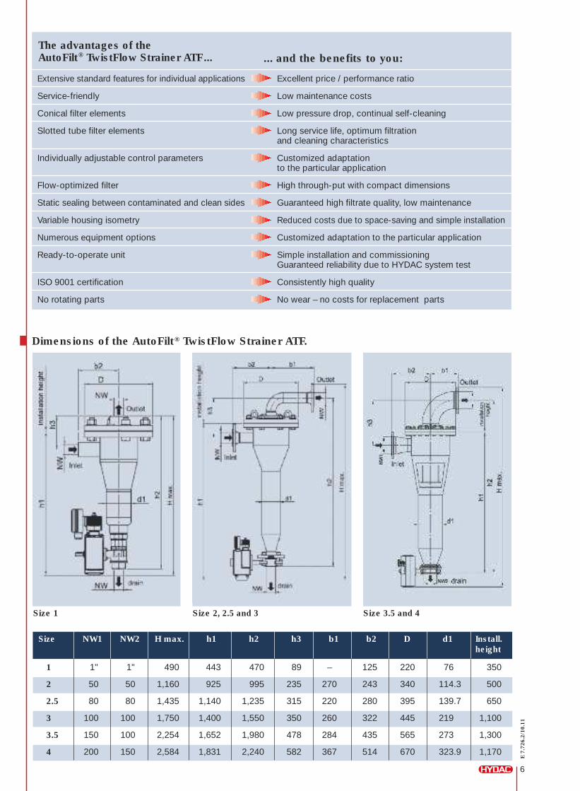
... and the benefits to you:
Extensive standard features for individual applications Excellent price / performance ratio
Service-friendly Low maintenance costs
Conical filter elements Low pressure drop, continual self-cleaning
Slotted tube filter elements Long service life, optimum filtrationand cleaning characteristics
Individually adjustable control parameters Customized adaptationto the particular application
Flow-optimized filter High through-put with compact dimensions
Static sealing between contaminated and clean sides Guaranteed high filtrate quality, low maintenance
Variable housing isometry Reduced costs due to space-saving and simple installation
Numerous equipment options Customized adaptation to the particular application
Ready-to-operate unit Simple installation and commissioningGuaranteed reliability due to HYDAC system test
ISO 9001 certification Consistently high quality
No rotating parts No wear – no costs for replacement parts
The advantages of theAutoFilt® TwistFlow Strainer ATF...
E7.
726.
2/10
.11
6
Dimensions of the AutoFilt® TwistFlow Strainer ATF.
Size 3.5 and 4Size 1 Size 2, 2.5 and 3
Size NW1 NW2 H max. h1 h2 h3 b1 b2 D d1 Install.height
1
2
2.5
3
3.5
4
1"
50
80
100
150
200
1"
50
80
100
100
150
490
1,160
1,435
1,750
2,254
2,584
443
925
1,140
1,400
1,652
1,831
470
995
1,235
1,550
1,980
2,240
89
235
315
350
478
582
125
243
280
322
435
514
220
340
395
445
565
670
76
114.3
139.7
219
273
323.9
350
500
650
1,100
1,300
1,170
–
270
220
260
284
367
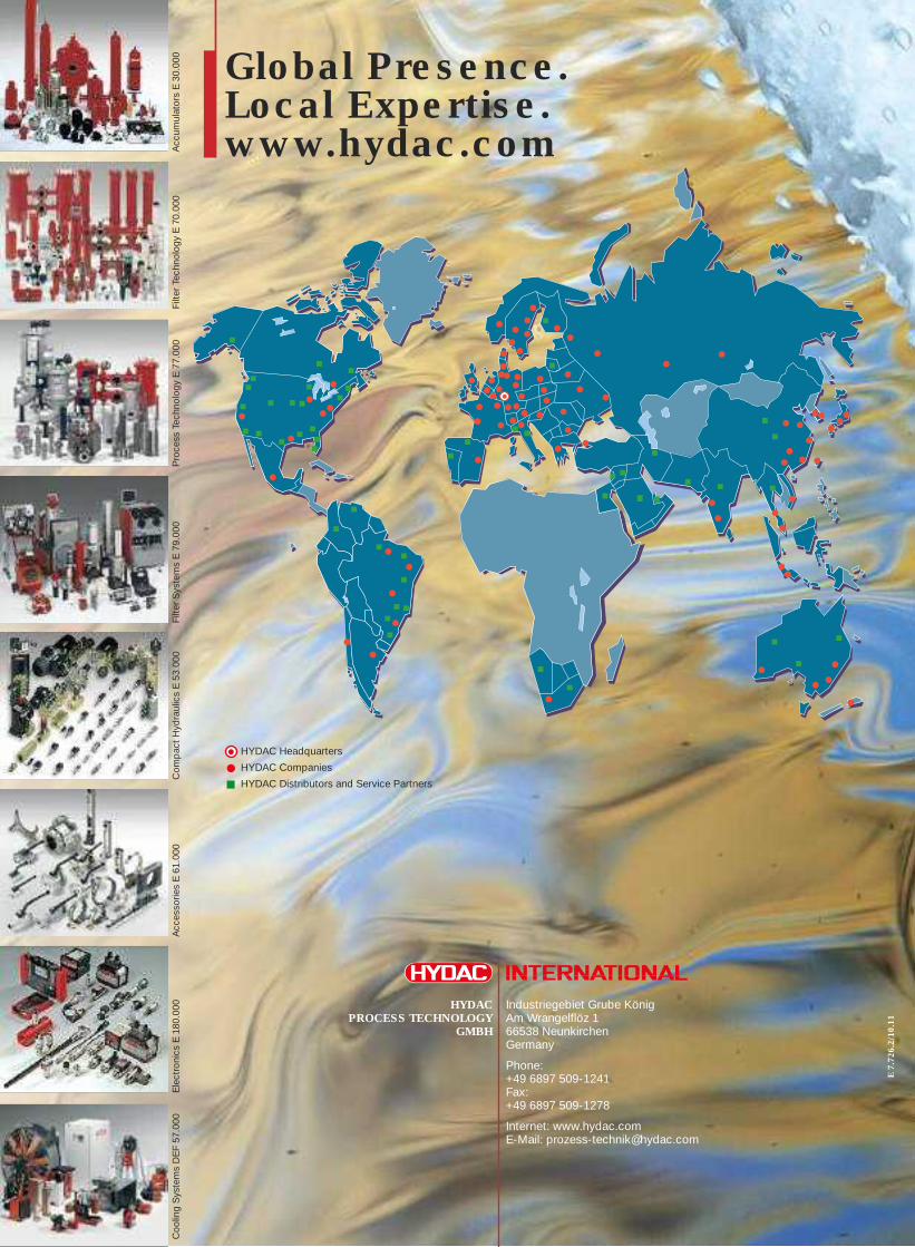
Global Presence.Local Expertise.www.hydac.com
HYDACPROCESS TECHNOLOGY
GMBH
Industriegebiet Grube KönigAm Wrangelflöz 166538 NeunkirchenGermany
Phone:+49 6897 509-1241Fax:+49 6897 509-1278
Internet: www.hydac.comE-Mail: [email protected]
E7.
726.
2/10
.11
Coo
lingSystemsDEF57
.000
Acc
esso
riesE61
.000
Com
pac
tHyd
raulicsE53
.000
Filte
rSystemsE79
.000
Filte
rTech
nology
E70
.000
Acc
umulatorsE30
.000
Electronics
E18
0.00
0Proce
ssTech
nology
E77
.000
HYDAC Headquarters
HYDAC Companies
HYDAC Distributors and Service Partners
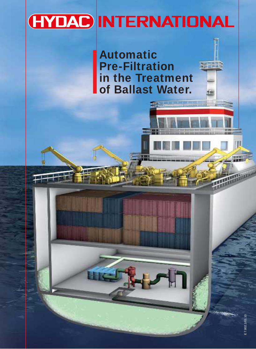
E 7
.802
.1/0
1.10
Automatic Pre-Filtration in the Treatment of Ballast Water.
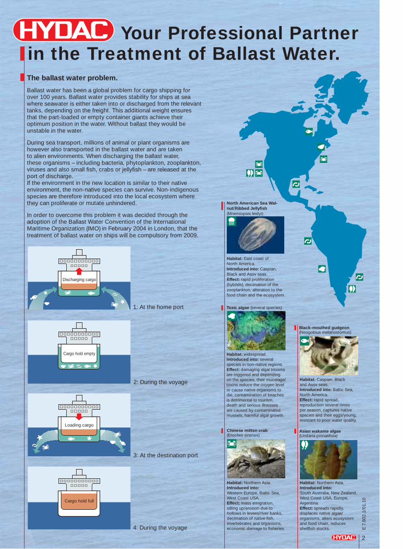
Your Professional Partnerin the Treatment of Ballast Water.
Toxic algae (several species)
Habitat: widespread.Introduced into: several species in non-native regions.Effect: damaging algal blooms are triggered and depending on the species, their mucelage/toxins reduce the oxygen level or cause native organisms to die, contamination of beaches is detrimental to tourism, death and serious illnesses are caused by contaminated mussels, harmful algal growth.
Chinese mitten crab(Eriocheir sinensis)
Habitat: Northern Asia.Introduced into: Western Europe, Baltic Sea, West Coast USA.Effect: mass emigration, silting up/erosion due to hollows in levees/river banks, decimation of native fi sh, invertebrates and organisms, economic damage to fi sheries.
Habitat: Caspian, Black and Asov seas. Introduced into: Baltic Sea, North America.Effect: rapid spread, reproduction several times per season, captures native species and their eggs/young, resistant to poor water quality.
Black-mouthed gudgeon (Neogobius melanostomus)
Habitat: Northern Asia.Introduced into: South Australia, New Zealand, West Coast USA, Europe, Argentina.Effect: spreads rapidly, displaces native algae/organisms, alters ecosystem and food chain, reduces shellfi sh stocks.
Asian wakame algae(Undaria pinnatifi da)
Habitat: East coast of North America.Introduced into: Caspian, Black and Asov seas.Effect: rapid proliferation (hybrids), decimation of the zooplankton, alteration to the food chain and the ecosystem.
North American Sea Wal-nut/Ribbed Jellyfi sh(Mnemiopsis leidyi)
2
E 7
.802
.1/0
1.10
The ballast water problem.
Ballast water has been a global problem for cargo shipping for over 100 years. Ballast water provides stability for ships at sea where seawater is either taken into or discharged from the relevant tanks, depending on the freight. This additional weight ensures that the part-loaded or empty container giants achieve their optimum position in the water. Without ballast they would be unstable in the water.
During sea transport, millions of animal or plant organisms are however also transported in the ballast water and are taken to alien environments. When discharging the ballast water, these organisms – including bacteria, phytoplankton, zooplankton, viruses and also small fi sh, crabs or jellyfi sh – are released at the port of discharge. If the environment in the new location is similar to their native environment, the non-native species can survive. Non-indigenous species are therefore introduced into the local ecosystem wherethey can proliferate or mutate unhindered.
In order to overcome this problem it was decided through the adoption of the Ballast Water Convention of the International Maritime Organization (IMO) in February 2004 in London, that the treatment of ballast water on ships will be compulsory from 2009.
1: At the home port
2: During the voyage
4: During the voyage
3: At the destination port
Discharging cargo
Cargo hold empty
Cargo hold full
Loading cargo
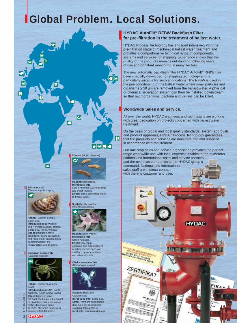
Global Problem. Local Solutions.HYDAC AutoFilt® RFBW Backfl ush Filter for pre-fi ltration in the treatment of ballast water.
HYDAC Process Technology has engaged intensively with the pre-fi ltration stage of mechanical ballast water treatment and provides a comprehensive technical range of components, systems and services for shipping. Experience shows that the quality of the products remains outstanding following years of use and constant monitoring in many sectors.
The new automatic backfl ush fi lter HYDAC AutoFilt® RFBW has been specially developed for shipping technology and is particularly suitable for such applications. The RFBW is used in the pre-conditioning of the ballast water where small particles and organisms ≥ 50 µm are removed from the ballast water. A physical or chemical separation system can then be installed downstream so that microorganisms, bacteria and viruses can be killed.
Worldwide Sales and Service.
All over the world, HYDAC engineers and technicians are working with great dedication on projects concerned with ballast water treatment.
On the basis of global and local quality standards, system approvals and product approvals, HYDAC Process Technology guarantees that the products and services are manufactured and supplied in accordance with requirement.
Our one-stop sales and service organisation provides the perfect range worldwide and with local expertise, thanks to the numerous national and international sales and service partners and the overseas companies at the HYDAC group’s command. National and international sales staff are in direct contact with the end customer and user.
European green crab (Carcinus maenas)
Habitat: European Atlantic coast.Introduced into: USA, South Australia, South Africa, Japan.Effect: highly invasive, the hard shell makes it resistant to predators, displaces native crabs, decimates many species, alters the ecosystem in rocky intertidal areas.
Cladocera water fl ea(Cercopagis pengoi)
Habitat: Black Sea, Caspian Sea.Introduced into: Baltic Sea.Effect: rampant populations dominate the zooplankton, clogging fi shing nets or trawl nets, economic damage.
Zebra mussel(Dreissena polymorpha)
Habitat: Eastern Europe, Black Sea.Introduced into: Western and Northern Europe, Ireland, Baltic Sea, North America.Effect: displaces native organisms, alters ecosystem and food chain, causes heavy contamination in the infrastructure and to ships.
Habitat: widespread.Introduced into: South America, Gulf of Mexico and other regions.Effect: some epidemics linked to ballast water.
Cholera (Vibrio cholerae)
Habitat: North Pacifi c.Introduced into: South Australia.Effect: very rapid, epidemic-like displacement of other species, feeds on shellfi sh, oysters, scallops and other mussels.
North Pacifi c starfi sh(Asterias amurensis)
3
E 7
.802
.1/0
1.10
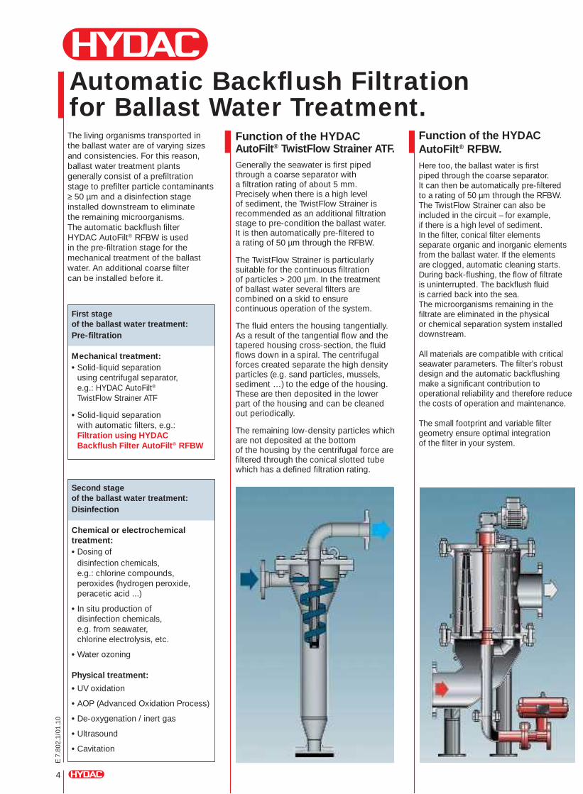
Automatic Backfl ush Filtration for Ballast Water Treatment.
4
E 7
.802
.1/0
1.10
The living organisms transported in the ballast water are of varying sizes and consistencies. For this reason, ballast water treatment plants generally consist of a prefi ltration stage to prefi lter particle contaminants ≥ 50 µm and a disinfection stage installed downstream to eliminate the remaining microorganisms. The automatic backfl ush fi lter HYDAC AutoFilt® RFBW is used in the pre-fi ltration stage for the mechanical treatment of the ballast water. An additional coarse fi lter can be installed before it.
Function of the HYDAC AutoFilt® TwistFlow Strainer ATF. Generally the seawater is fi rst piped through a coarse separator with a fi ltration rating of about 5 mm. Precisely when there is a high level of sediment, the TwistFlow Strainer is recommended as an additional fi ltration stage to pre-condition the ballast water. It is then automatically pre-fi ltered to a rating of 50 µm through the RFBW.
The TwistFlow Strainer is particularly suitable for the continuous fi ltration of particles > 200 µm. In the treatment of ballast water several fi lters are combined on a skid to ensure continuous operation of the system.
The fl uid enters the housing tangentially. As a result of the tangential fl ow and the tapered housing cross-section, the fl uid fl ows down in a spiral. The centrifugal forces created separate the high density particles (e.g. sand particles, mussels, sediment …) to the edge of the housing. These are then deposited in the lower part of the housing and can be cleaned out periodically.
The remaining low-density particles which are not deposited at the bottom of the housing by the centrifugal force are fi ltered through the conical slotted tube which has a defi ned fi ltration rating.
Function of the HYDAC AutoFilt® RFBW.Here too, the ballast water is fi rst piped through the coarse separator. It can then be automatically pre-fi ltered to a rating of 50 µm through the RFBW. The TwistFlow Strainer can also be included in the circuit – for example, if there is a high level of sediment. In the fi lter, conical fi lter elements separate organic and inorganic elements from the ballast water. If the elements are clogged, automatic cleaning starts. During back-fl ushing, the fl ow of fi ltrate is uninterrupted. The backfl ush fl uid is carried back into the sea. The microorganisms remaining in the fi ltrate are eliminated in the physical or chemical separation system installed downstream.
All materials are compatible with critical seawater parameters. The fi lter’s robust design and the automatic backfl ushing make a signifi cant contribution to operational reliability and therefore reduce the costs of operation and maintenance.
The small footprint and variable fi lter geometry ensure optimal integration of the fi lter in your system.
First stage of the ballast water treatment:Pre-fi ltration
Mechanical treatment:• Solid-liquid separation using centrifugal separator, e.g.: HYDAC AutoFilt®
TwistFlow Strainer ATF
• Solid-liquid separation with automatic fi lters, e.g.: Filtration using HYDAC Backfl ush Filter AutoFilt® RFBW
Second stage of the ballast water treatment:Disinfection
Chemical or electrochemical treatment:• Dosing of disinfection chemicals, e.g.: chlorine compounds, peroxides (hydrogen peroxide, peracetic acid ...)
• In situ production of disinfection chemicals, e.g. from seawater, chlorine electrolysis, etc.
• Water ozoning
Physical treatment:
• UV oxidation
• AOP (Advanced Oxidation Process)
• De-oxygenation / inert gas
• Ultrasound
• Cavitation
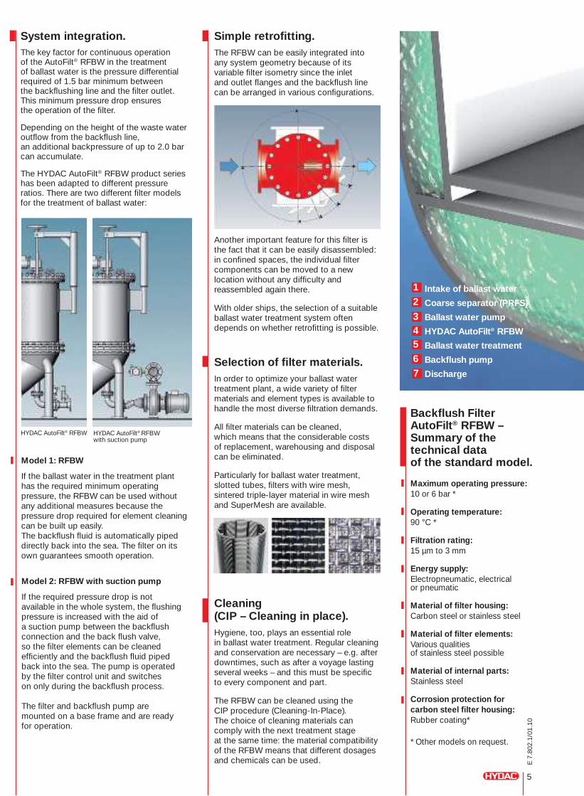
System integration.The key factor for continuous operation of the AutoFilt® RFBW in the treatment of ballast water is the pressure differential required of 1.5 bar minimum between the backfl ushing line and the fi lter outlet. This minimum pressure drop ensures the operation of the fi lter.
Depending on the height of the waste water outfl ow from the backfl ush line, an additional backpressure of up to 2.0 bar can accumulate.
The HYDAC AutoFilt® RFBW product series has been adapted to different pressure ratios. There are two different fi lter models for the treatment of ballast water:
Model 1: RFBW
If the ballast water in the treatment plant has the required minimum operating pressure, the RFBW can be used without any additional measures because the pressure drop required for element cleaning can be built up easily. The backfl ush fl uid is automatically piped directly back into the sea. The fi lter on its own guarantees smooth operation.
Model 2: RFBW with suction pump
If the required pressure drop is not available in the whole system, the fl ushing pressure is increased with the aid of a suction pump between the backfl ush connection and the back fl ush valve, so the fi lter elements can be cleaned effi ciently and the backfl ush fl uid piped back into the sea. The pump is operated by the fi lter control unit and switches on only during the backfl ush process.
The fi lter and backfl ush pump are mounted on a base frame and are ready for operation.
Simple retrofi tting.The RFBW can be easily integrated into any system geometry because of its variable fi lter isometry since the inlet and outlet fl anges and the backfl ush line can be arranged in various confi gurations.
Another important feature for this fi lter is the fact that it can be easily disassembled: in confi ned spaces, the individual fi lter components can be moved to a new location without any diffi culty and reassembled again there.
With older ships, the selection of a suitable ballast water treatment system often depends on whether retrofi tting is possible.
Selection of fi lter materials.In order to optimize your ballast water treatment plant, a wide variety of fi lter materials and element types is available to handle the most diverse fi ltration demands.
All fi lter materials can be cleaned, which means that the considerable costs of replacement, warehousing and disposal can be eliminated.
Particularly for ballast water treatment, slotted tubes, fi lters with wire mesh, sintered triple-layer material in wire mesh and SuperMesh are available.
Cleaning (CIP – Cleaning in place).Hygiene, too, plays an essential role in ballast water treatment. Regular cleaning and conservation are necessary – e.g. after downtimes, such as after a voyage lasting several weeks – and this must be specifi c to every component and part.
The RFBW can be cleaned using the CIP procedure (Cleaning-In-Place). The choice of cleaning materials can comply with the next treatment stage at the same time: the material compatibility of the RFBW means that different dosages and chemicals can be used.
HYDAC AutoFilt® RFBW HYDAC AutoFilt® RFBW with suction pump
5
E 7
.802
.1/0
1.10
Backfl ush Filter AutoFilt® RFBW – Summary of the technical dataof the standard model.
Maximum operating pressure:10 or 6 bar *
Operating temperature:90 °C *
Filtration rating:15 µm to 3 mm
Energy supply:Electropneumatic, electrical or pneumatic
Material of fi lter housing:Carbon steel or stainless steel
Material of fi lter elements:Various qualities of stainless steel possible
Material of internal parts:Stainless steel
Corrosion protection for carbon steel fi lter housing:Rubber coating*
* Other models on request.
12
34567
Intake of ballast water
Coarse separator (PRFS)
Ballast water pump
HYDAC AutoFilt® RFBW
Ballast water treatment
Backfl ush pump
Discharge

6
E 7
.802
.1/0
1.10
HYDAC AutoFilt® RFBW in operation.An accredited Institute has defi ned the separation rates of the RFBW during operation in a ballast water treatment plant.The graph shows the separation rate of living plankton before and after the fi lter.
The results of this test are convincing: For a fi ltration rating of 50 µm the zooplankton (multicell) is almost completely fi ltered out. 90 % of all living plankton is eliminated at a fi ltration rating of 50 µm.
1
3
245
6
7
Organisms Sizes IMO Requirement Average concentration in seawater
Predominantly ≥ 50 µm < 10 living organisms/m3 103 to 105/m3
zooplankton (multicell)
Zooplankton(single cell) 10 to 50 µm < 10 living organisms/ml 102 to 104/ml
Phytoplankton
Vibrio cholerae 0.1 to 1 µm < 1 CFU*/100 ml or Occasionally present < 1 CFU*/g zooplankton mass
Escherichia coli 0.1 to 1 µm < 250 CFU*/100 ml Occasionally present
Enterococci 0.1 to 1 µm < 100 CFU*/100 ml Occasionally present
CFU* = Colony forming unit
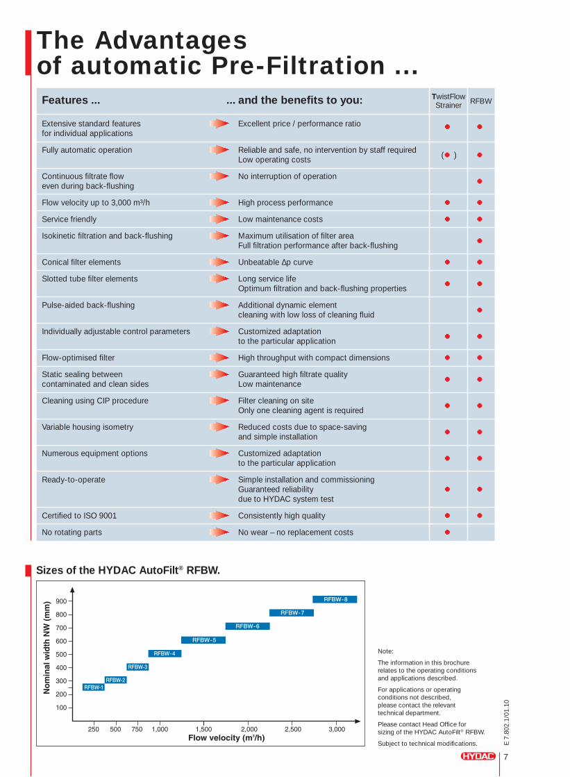
7
E 7
.802
.1/0
1.10
Sizes of the HYDAC AutoFilt® RFBW.
The Advantages of automatic Pre-Filtration ...
Note:
The information in this brochure relates to the operating conditionsand applications described.
For applications or operating conditions not described, please contact the relevant technical department.
Please contact Head Offi ce for sizing of the HYDAC AutoFilt® RFBW.
Subject to technical modifi cations.
Features ... ... and the benefi ts to you: TwistFlow RFBW
Strainer
Extensive standard features Excellent price / performance ratio for individual applications
●
●
Fully automatic operation Reliable and safe, no intervention by staff required Low operating costs (● ) ●
Continuous fi ltrate fl ow No interruption of operation even during back-fl ushing ●
Flow velocity up to 3,000 m³/h High process performance ● ●
Service friendly Low maintenance costs ● ●
Isokinetic fi ltration and back-fl ushing Maximum utilisation of fi lter area Full fi ltration performance after back-fl ushing ●
Conical fi lter elements Unbeatable Δp curve ● ●
Slotted tube fi lter elements Long service life Optimum fi ltration and back-fl ushing properties ● ●
Pulse-aided back-fl ushing Additional dynamic element cleaning with low loss of cleaning fl uid ●
Individually adjustable control parameters Customized adaptation to the particular application ● ●
Flow-optimised fi lter High throughput with compact dimensions ● ●
Static sealing between Guaranteed high fi ltrate quality contaminated and clean sides Low maintenance ● ●
Cleaning using CIP procedure Filter cleaning on site Only one cleaning agent is required ● ●
Variable housing isometry Reduced costs due to space-saving and simple installation ● ●
Numerous equipment options Customized adaptation to the particular application ● ●
Ready-to-operate Simple installation and commissioning Guaranteed reliability ● ● due to HYDAC system test
Certifi ed to ISO 9001 Consistently high quality ● ●
No rotating parts No wear – no replacement costs ●
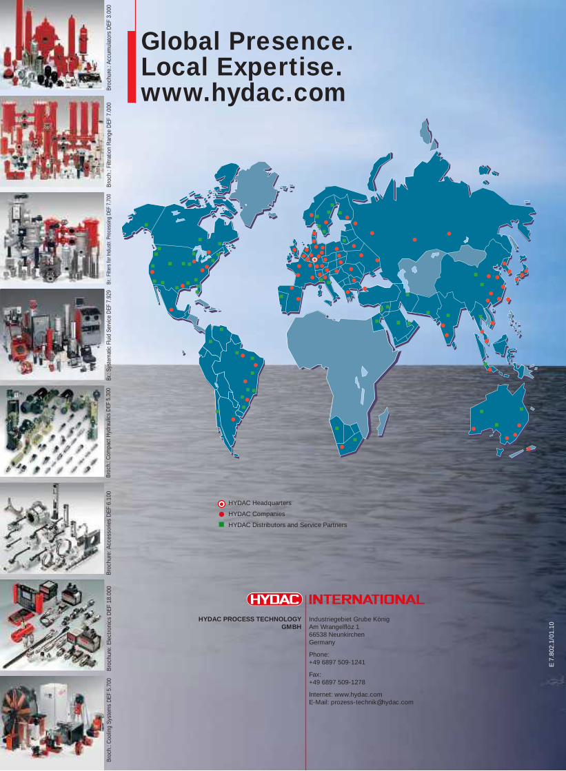
E 7
.802
.1/0
1.10
Industriegebiet Grube KönigAm Wrangelfl öz 166538 NeunkirchenGermany
Phone:+49 6897 509-1241
Fax:+49 6897 509-1278
Internet: www.hydac.comE-Mail: [email protected]
HYDAC PROCESS TECHNOLOGYGMBH
Global Presence.Local Expertise.www.hydac.com
HYDAC Headquarters
HYDAC Companies
HYDAC Distributors and Service Partners
Br.:
Filte
rs fo
r Ind
ustr.
Pro
cess
ing
DEF
7.70
0 Br
.: Sy
stem
atic
Flu
id S
ervi
ce D
EF 7
.929
Bro
ch.:
Com
pact
Hyd
raul
ics
DEF
5.3
00 B
roch
ure:
Acc
esso
ries
DEF
6.1
00 B
roch
ure:
Ele
ctro
nics
DEF
18.
000
Bro
ch.:
Coo
ling
Syst
ems
DEF
5.7
00 B
roch
.: Fi
ltrat
ion
Ran
ge D
EF 7
.000
Bro
chur
e.: A
ccum
ulat
ors
DEF
3.0
00
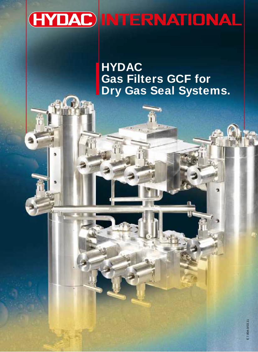
E 7
.804
.0/0
3.11
HYDAC Gas Filters GCF for Dry Gas Seal Systems.
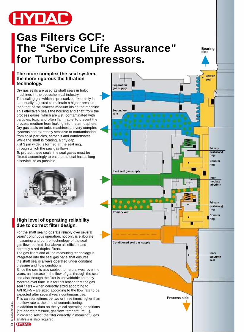
2
E 7
.804
.0/0
3.11
Gas Filters GCF: The "Service Life Assurance" for Turbo Compressors.The more complex the seal system, the more rigorous the filtration technology.Dry gas seals are used as shaft seals in turbo machines in the petrochemical industry. The sealing gas which is pressurized externally is continually adjusted to maintain a higher pressure than that of the process medium inside the machine. This effectively seals the housing and shaft from the process gases (which are wet, contaminated with particles, toxic and often flammable) to prevent the process medium from leaking into the atmosphere.Dry gas seals on turbo machines are very complex systems and extremely sensitive to contamination from solid particles, aerosols and condensates. While the shaft is rotating, a tiny gap, just 3 μm wide, is formed at the seal ring, through which the seal gas flows.To protect these seals, the seal gases must be filtered accordingly to ensure the seal has as long a service life as possible.
High level of operating reliabilitydue to correct filter design. For the shaft seal to operate reliably over several years’ continuous operation, not only is elaborate measuring and control technology of the seal gas flow required, but above all, efficient and correctly sized duplex filters. The gas filters and all the measuring technology is integrated into the seal gas panel that ensures the shaft seal is always operated under constant pressure and flow conditions.Since the seal is also subject to natural wear over the years, an increase in the flow of gas through the seal and also through the filter is unavoidable on many systems over time. It is for this reason that the gas seal filters – when correctly sized according to API 614-5 – are sized according to the flow rate to be expected after several years continuous use. This can sometimes be two or three times higher than the flow rate at the time of commissioning.In addition to data on the typical operating conditions (pre-charge pressure, gas flow, temperature …), in order to select the filter correctly, a meaningful gas analysis is also required.
Bearing side
Separationgas supply
Conditioned seal gas supply
Primary vent
Inert seal gas supply
Secondary vent
Primary(stationary)ring
Primary(stationary)ring
Counter ring
Barrierseal
Inter-mediatelabyrinth
Counter ring
Innerlabyrinthseal
Process side
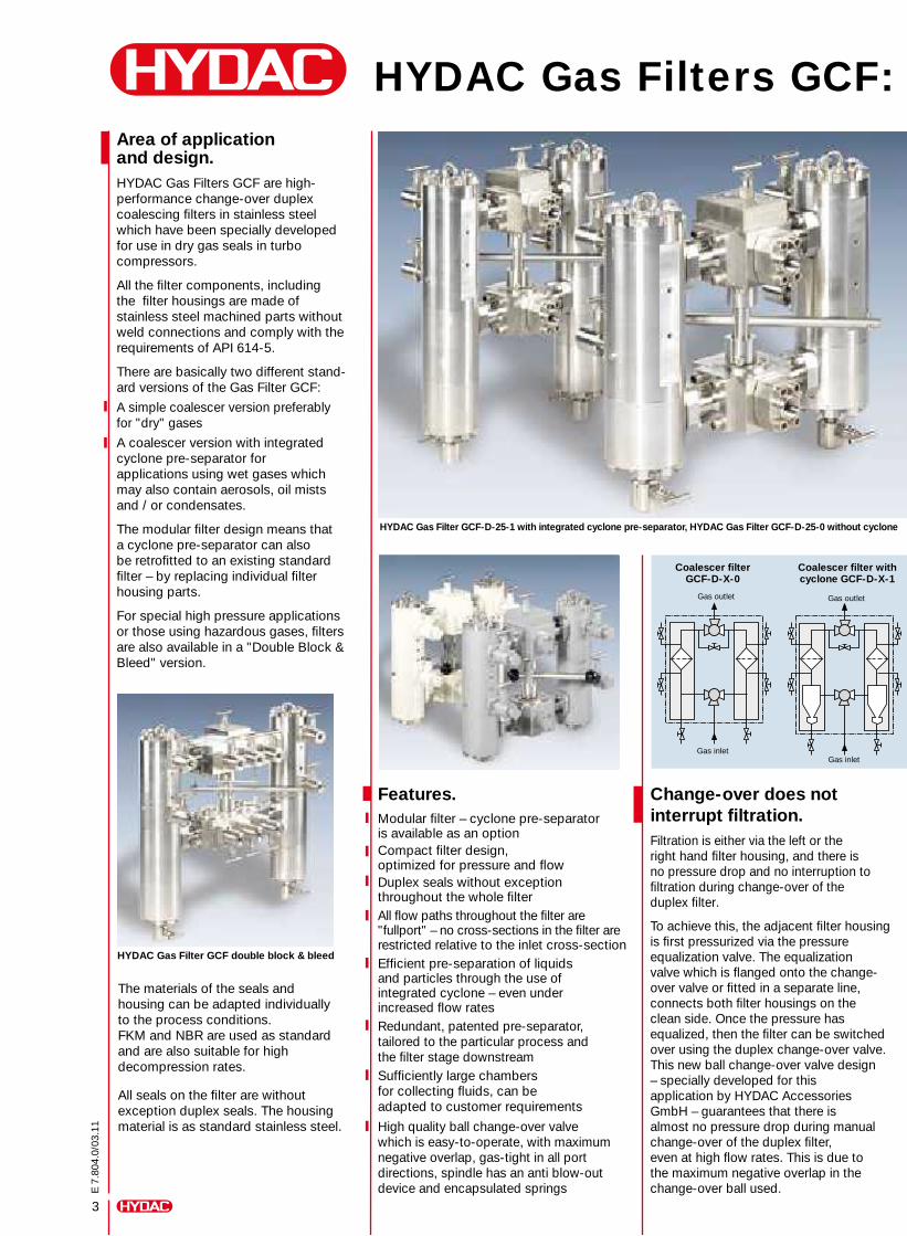
Area of application and design.HYDAC Gas Filters GCF are high- performance change-over duplex coalescing filters in stainless steel which have been specially developed for use in dry gas seals in turbo compressors.
All the filter components, including the filter housings are made of stainless steel machined parts without weld connections and comply with the requirements of API 614-5.
There are basically two different stand-ard versions of the Gas Filter GCF:
A simple coalescer version preferably for "dry" gases
A coalescer version with integrated cyclone pre-separator for applications using wet gases which may also contain aerosols, oil mists and / or condensates.
The modular filter design means that a cyclone pre-separator can also be retrofitted to an existing standard filter – by replacing individual filter housing parts.
For special high pressure applications or those using hazardous gases, filters are also available in a "Double Block & Bleed" version.
3
E 7
.804
.0/0
3.11
The materials of the seals and housing can be adapted individually to the process conditions. FKM and NBR are used as standard and are also suitable for high decompression rates. All seals on the filter are without exception duplex seals. The housing material is as standard stainless steel.
Change-over does not interrupt filtration.Filtration is either via the left or the right hand filter housing, and there is no pressure drop and no interruption to filtration during change-over of the duplex filter.
To achieve this, the adjacent filter housing is first pressurized via the pressure equalization valve. The equalization valve which is flanged onto the change-over valve or fitted in a separate line, connects both filter housings on the clean side. Once the pressure has equalized, then the filter can be switched over using the duplex change-over valve. This new ball change-over valve design – specially developed for this application by HYDAC Accessories GmbH – guarantees that there is almost no pressure drop during manual change-over of the duplex filter, even at high flow rates. This is due to the maximum negative overlap in the change-over ball used.
HYDAC Gas Filter GCF-D-25-1 with integrated cyclone pre-separator, HYDAC Gas Filter GCF-D-25-0 without cyclone
HYDAC Gas Filter GCF double block & bleed
Features.Modular filter – cyclone pre-separator is available as an option Compact filter design, optimized for pressure and flowDuplex seals without exception throughout the whole filterAll flow paths throughout the filter are "fullport" – no cross-sections in the filter are restricted relative to the inlet cross-sectionEfficient pre-separation of liquids and particles through the use of integrated cyclone – even under increased flow ratesRedundant, patented pre-separator, tailored to the particular process and the filter stage downstreamSufficiently large chambers for collecting fluids, can be adapted to customer requirements
High quality ball change-over valve which is easy-to-operate, with maximum negative overlap, gas-tight in all port directions, spindle has an anti blow-out device and encapsulated springs
Gas outlet Gas outlet
Gas inletGas inlet
Coalescer filter GCF-D-X-0
Coalescer filter withcyclone GCF-D-X-1
HYDAC Gas Filters GCF: Optimum fluid pre-separation, highly efficient element technology, reliable over extended operating periods.
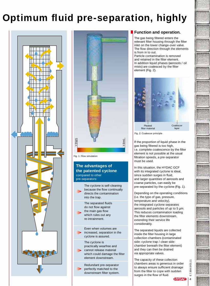
Fig. 1: Flow simulation
HYDAC Gas Filter GCF-D-25-1 with integrated cyclone pre-separator, HYDAC Gas Filter GCF-D-25-0 without cyclone
If the proportion of liquid phase in the gas being filtered is too high, i.e. complete coalescence by the filter element is not possible at the usual filtration speeds, a pre-separator must be used.
In this situation, the HYDAC GCF with its integrated cyclone is ideal, since sudden surges in fluid, and larger quantities of aerosols and coarse particles, can easily be pre-separated by the cyclone (Fig. 1).
Depending on the operating conditions (i.e. the type of gas, pressure, temperature and velocity), the integrated cyclone separates aerosols and particles of up to 5 μm. This reduces contamination loading the filter elements downstream, extending their service life considerably.
The separated liquids are collected inside the filter housing in large collection chambers (contaminated side: cyclone trap / clean side: chamber beneath the filter element) and they can then be drained via appropriate valves.
The capacity of these collection chambers areas is generous in order to always ensure sufficient drainage from the filter to cope with sudden surges in the flow of fluid.
Function and operation.The gas being filtered enters the relevant filter housing through the filter inlet on the lower change-over valve. The flow direction through the elements is from in to out. Particle contamination is removed and retained in the filter element. In addition liquid phases (aerosols / oil mists) are coalesced by the filter element (Fig. 2).
Fig. 2: Coalescer principle
Coalescer layer
Pleated filter material
E 7
.804
.0/0
3.11
4
HYDAC Gas Filters GCF: Optimum fluid pre-separation, highly efficient element technology, reliable over extended operating periods.
The advantages of the patented cyclonecompared to other pre-separators:
The cyclone is self-cleaning because the flow continually directs the contamination into the trap.
The separated fluids do not flow against the main gas flow which rules out any re-intrainment.
Even when volumes are increased, separation in the cyclone is assured.
The cyclone is practically wearfree and cannot release material which could damage the filter element downstream.
Redundant pre-separator perfectly matched to the downstream filter system.
V (h
igh)
V (l
ow)
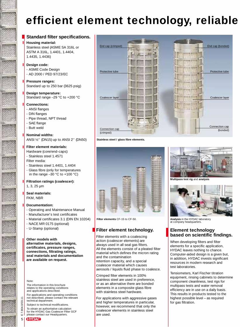
Standard filter specifications.Housing material:Stainless steel (ASME SA 316L or ASTM A 316L, 1.4401, 1.4404, 1.4435, 1.4436)
Design code:- ASME Code Design - AD 2000 / PED 97/23/EC
Pressure ranges:Standard up to 250 bar (3625 psig)
Design temperature:Standard range –29 °C to +200 °C
Connections:- ANSI flanges - DIN flanges- Pipe thread, NPT thread- SAE flange - Butt weld
Nominal widths:ANSI ½'' (DN15) up to ANSI 2'' (DN50)
Filter element materials:Hardware (core/end-caps):- Stainless steel 1.4571 Filter media:- Stainless steel 1.4401, 1.4404- Glass fibre (only for temperatures in the range –30 °C to +100 °C)
Filtration ratings (coalescer):1, 3, 25 μm
Seal materials:FKM, NBR
Documentation:- Operating and Maintenance Manual- Manufacturer's test certificates- Material certificates 3.1 (DIN EN 10204) - NACE MR 0175 (optional) - U-Stamp (optional)
Other models with alternative materials, designs, certificates, pressure ranges, connections, filtrating ratings, seal materials and documentation are available on request.
Note:
The information in this brochure relates to the operating conditions and applications described.
For applications and operating conditions not described, please contact the relevant technical department.
Subject to technical modifications.
To obtain an authoritative calculation for the HYDAC Gas Coalescer Filter GCF please contact our Headquarters.
Filter elements CF-15 to CF-50.
Filter element technology.Filter elements with a coalescing action (coalescer elements) are always used in all seal gas filters. All the elements consist of a pleated filter material which defines the micron rating and the contamination retention capacity, and a special coalescer material which causes aerosols / liquids fluid phase to coalesce.
Crimped filter elements in 100% stainless steel are used in preference, or as an alternative there are bonded elements in a composite glass fibre with stainless steel hardware.
For applications with aggressive gases and higher temperatures in particular, however, we recommend that only the coalescer elements in stainless steel are used.
Stainless steel / glass fibre elements.
End cap (bonded)
Connection cap (bonded)
Protective tube
Coalescer layer
End cap (crimped)
Connection cap (crimped)
Protective tube
Coalescer layer
Element technology based on scientific findings.When developing filters and filter elements for a specific application, HYDAC leaves nothing to chance. Computer-aided design is a given but, in addition, HYDAC invests significant resources in modern research and test laboratories.
Tensiometers, Karl Fischer titration equipment, rinsing cabinets to determine component cleanliness, test rigs for multipass tests and water removal efficiency are in use on a daily basis. This results in products tested to the highest possible level – as required for gas filtration.
Multipass test rig and analysis
Analysis in the HYDAC laboratory at company headquarters.
5
E 7
.804
.0/0
3.11
HYDAC Gas Filters GCF: Optimum fluid pre-separation, highly efficient element technology, reliable over extended operating periods.
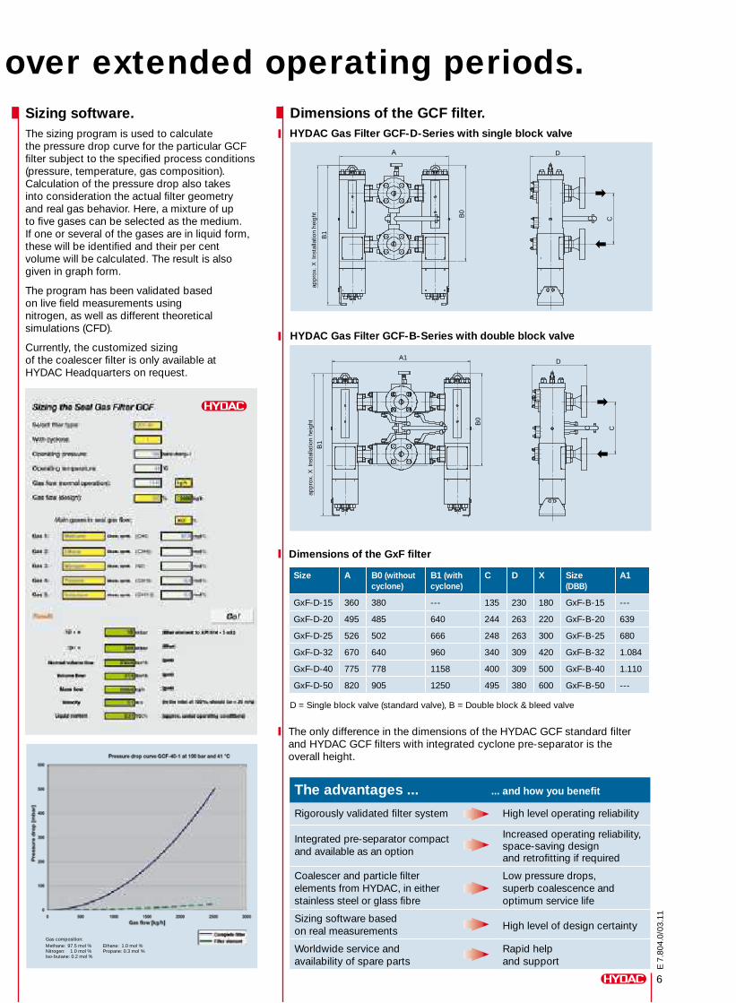
HYDAC Gas Filter GCF-D-Series with single block valve
6
E 7
.804
.0/0
3.11
Sizing software.The sizing program is used to calculate the pressure drop curve for the particular GCF filter subject to the specified process conditions (pressure, temperature, gas composition). Calculation of the pressure drop also takes into consideration the actual filter geometry and real gas behavior. Here, a mixture of up to five gases can be selected as the medium. If one or several of the gases are in liquid form, these will be identified and their per cent volume will be calculated. The result is also given in graph form.
The program has been validated based on live field measurements using nitrogen, as well as different theoretical simulations (CFD).
Currently, the customized sizing of the coalescer filter is only available at HYDAC Headquarters on request.
Gas composition: Methane: 97.5 mol % Ethane: 1.0 mol %Nitrogen: 1.0 mol % Propane: 0.3 mol %Iso-butane: 0.2 mol %
Multipass test rig and analysis
Dimensions of the GCF filter.
The only difference in the dimensions of the HYDAC GCF standard filter and HYDAC GCF filters with integrated cyclone pre-separator is the overall height.
HYDAC Gas Filter GCF-B-Series with double block valve
Dimensions of the GxF filter
Size A B0 (without cyclone)
B1 (with cyclone)
C D X Size (DBB)
A1
GxF-D-15 360 380 --- 135 230 180 GxF-B-15 ---
GxF-D-20 495 485 640 244 263 220 GxF-B-20 639
GxF-D-25 526 502 666 248 263 300 GxF-B-25 680
GxF-D-32 670 640 960 340 309 420 GxF-B-32 1.084
GxF-D-40 775 778 1158 400 309 500 GxF-B-40 1.110
GxF-D-50 820 905 1250 495 380 600 GxF-B-50 ---
D = Single block valve (standard valve), B = Double block & bleed valve
The advantages ... ... and how you benefit
Rigorously validated filter system High level operating reliability
Integrated pre-separator compact and available as an option
Increased operating reliability, space-saving designand retrofitting if required
Coalescer and particle filter elements from HYDAC, in eitherstainless steel or glass fibre
Low pressure drops, superb coalescence and optimum service life
Sizing software based on real measurements High level of design certainty
Worldwide service andavailability of spare parts
Rapid help and support
B1
B0
A1
C
D
B1
B0 C
D
C
HYDAC Gas Filters GCF: Optimum fluid pre-separation, highly efficient element technology, reliable over extended operating periods.
app
rox.
X I
nsta
llatio
n he
ight
app
rox.
X I
nsta
llatio
n he
ight
C
A
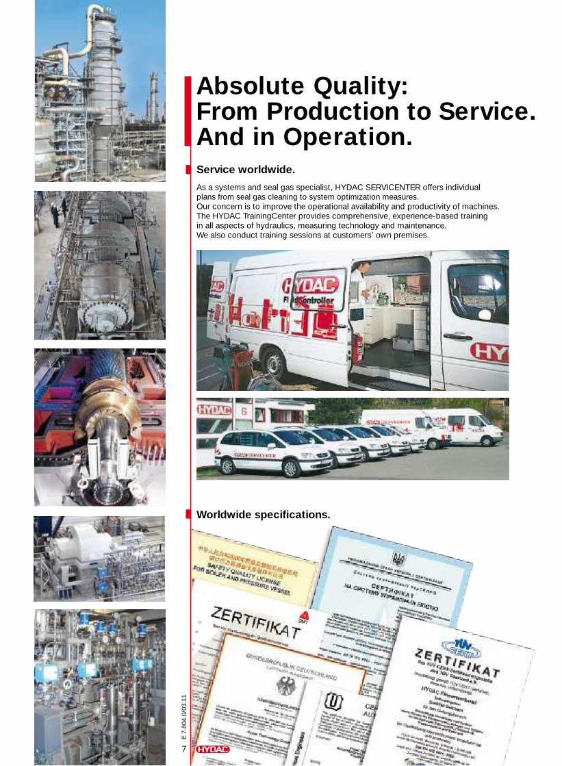
7
E 7
.804
.0/0
3.11
Absolute Quality: From Production to Service. And in Operation.
Worldwide specifications.
Service worldwide.
As a systems and seal gas specialist, HYDAC SERVICENTER offers individual plans from seal gas cleaning to system optimization measures.Our concern is to improve the operational availability and productivity of machines.The HYDAC TrainingCenter provides comprehensive, experience-based training in all aspects of hydraulics, measuring technology and maintenance. We also conduct training sessions at customers’ own premises.
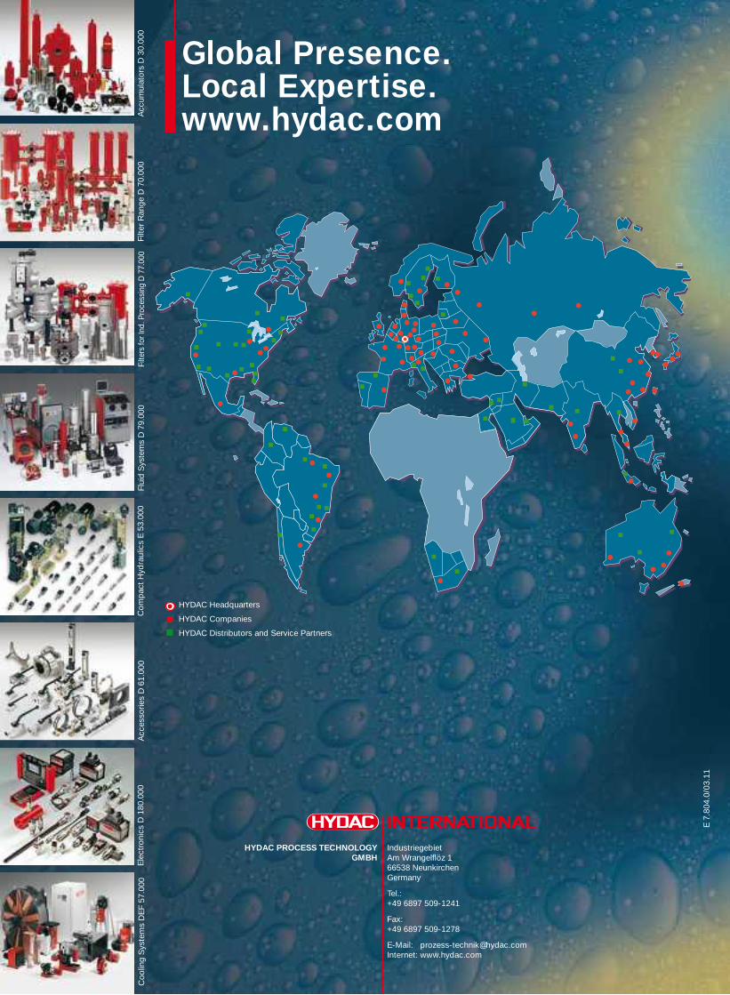
E 7
.804
.0/0
3.11
Global Presence.Local Expertise.www.hydac.com
HYDAC Headquarters
HYDAC Companies
HYDAC Distributors and Service Partners
IndustriegebietAm Wrangelflöz 166538 NeunkirchenGermany
Tel.: +49 6897 509-1241
Fax: +49 6897 509-1278
E-Mail: [email protected] Internet: www.hydac.com
HYDAC PROCESS TECHNOLOGY GMBH
Filte
rs fo
r Ind
. Pro
cess
ing
D 7
7.00
0Fl
uid
Sys
tem
s D
79.
000
Com
pac
t H
ydra
ulic
s E
53.
000
Acc
esso
ries
D 6
1.00
0E
lect
roni
cs D
180
.000
Coo
ling
Sys
tem
s D
EF
57.0
00Fi
lter
Ran
ge D
70.
000
Acc
umul
ator
s D
30.
000
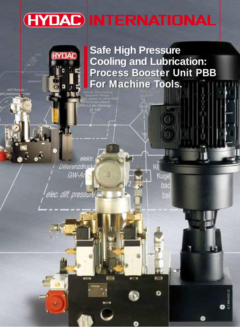
E 7
.809
.0/0
2.12
Safe High PressureCooling and Lubrication:Process Booster Unit PBBFor Machine Tools.
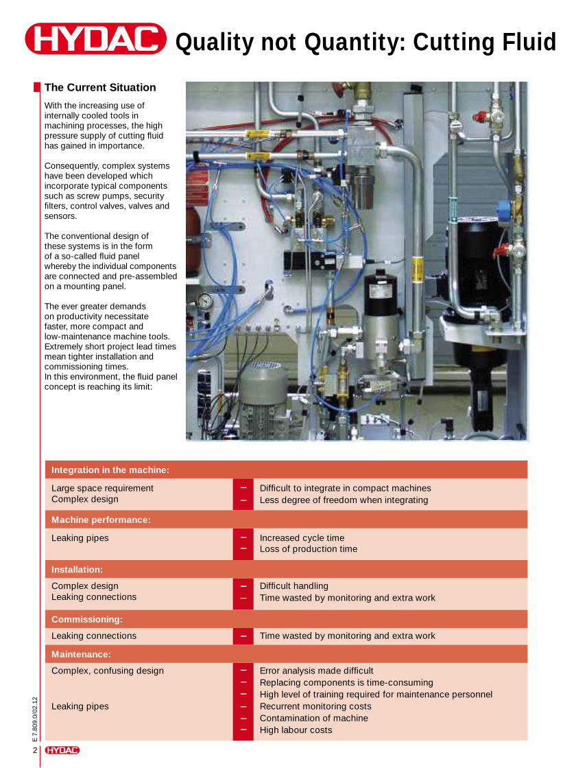
2
E 7
.809
.0/0
2.12
Quality not Quantity: Cutting Fluid
The Current Situation
With the increasing use of internally cooled tools in machining processes, the high pressure supply of cutting fluid has gained in importance.
Consequently, complex systems have been developed which incorporate typical components such as screw pumps, security filters, control valves, valves and sensors.
The conventional design of these systems is in the form of a so-called fluid panel whereby the individual components are connected and pre-assembled on a mounting panel.
The ever greater demands on productivity necessitate faster, more compact and low-maintenance machine tools. Extremely short project lead times mean tighter installation and commissioning times.In this environment, the fluid panel concept is reaching its limit:
Integration in the machine:
Large space requirement Complex design
––
Difficult to integrate in compact machines Less degree of freedom when integrating
Machine performance:
Leaking pipes ––
Increased cycle time Loss of production time
Installation:
Complex design Leaking connections
––
Difficult handling Time wasted by monitoring and extra work
Commissioning:
Leaking connections – Time wasted by monitoring and extra work
Maintenance:
Complex, confusing design
Leaking pipes
––––––
Error analysis made difficult Replacing components is time-consuming High level of training required for maintenance personnel Recurrent monitoring costs Contamination of machine High labour costs
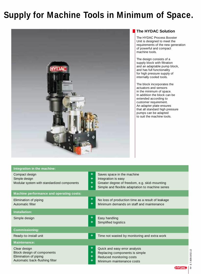
Supply for Machine Tools in Minimum of Space.
The HYDAC Solution
The HYDAC Process Booster Unit is designed to meet the requirements of the new generation of powerful and compact machine tools.
The design consists of a supply block with filtration and an adaptable pump block, and has full functionality for high pressure supply of internally cooled tools.
The block incorporates the actuators and sensors in the minimum of space.In addition the block can be extended according to customer requirement.An adapter plate ensures that all standard high pressure pumps can be adapted to suit the machine tools.
Integration in the machine:
Compact designSimple designModular system with standardized components
++++
Saves space in the machineIntegration is easy Greater degree of freedom, e.g. skid-mountingSimple and flexible adaptation to machine series
Machine performance and operating costs:
Elimination of pipingAutomatic filter
++
No loss of production time as a result of leakageMinimum demands on staff and maintenance
Installation:
Simple design ++
Easy handlingSimplified logistics
Commissioning:
Ready-to-install unit + Time not wasted by monitoring and extra work
Maintenance:
Clear designBlock design of componentsElimination of pipingAutomatic back-flushing filter
++++
Quick and easy error analysis Replacing components is simple Reduced monitoring costs Minimum maintenance costs
3
E 7
.809
.0/0
2.12
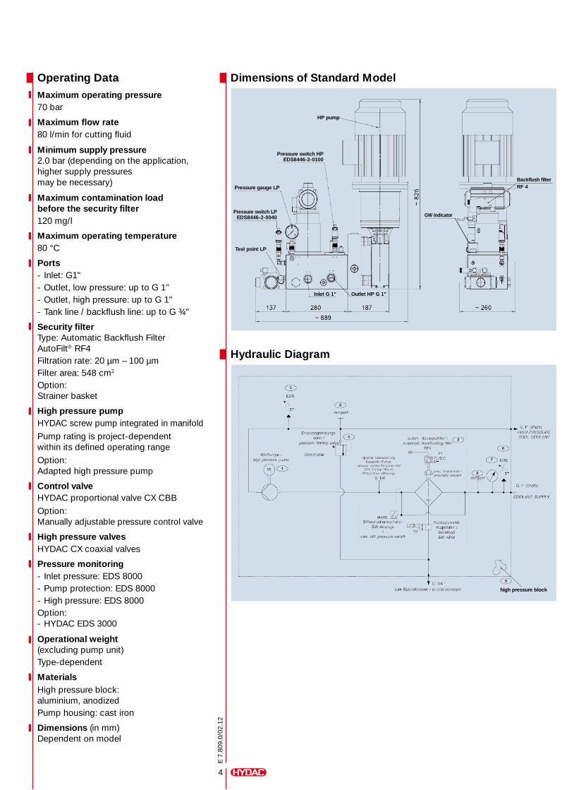
4
E 7
.809
.0/0
2.12
Operating DataMaximum operating pressure70 bar
Maximum flow rate80 l/min for cutting fluid
Minimum supply pressure2.0 bar (depending on the application, higher supply pressures may be necessary)
Maximum contamination load before the security filter120 mg/l
Maximum operating temperature80 °C
Ports- Inlet: G1"- Outlet, low pressure: up to G 1"- Outlet, high pressure: up to G 1"- Tank line / backflush line: up to G ¾"
Security filterType: Automatic Backflush Filter AutoFilt® RF4Filtration rate: 20 μm – 100 μmFilter area: 548 cm2
Option:Strainer basket
High pressure pumpHYDAC screw pump integrated in manifold
Pump rating is project-dependentwithin its defined operating range
Option:Adapted high pressure pump
Control valveHYDAC proportional valve CX CBB
Option:Manually adjustable pressure control valve
High pressure valvesHYDAC CX coaxial valves
Pressure monitoring- Inlet pressure: EDS 8000- Pump protection: EDS 8000- High pressure: EDS 8000Option:- HYDAC EDS 3000
Operational weight (excluding pump unit)Type-dependent
MaterialsHigh pressure block: aluminium, anodizedPump housing: cast iron
Dimensions (in mm)Dependent on model
Dimensions of Standard Model
Hydraulic Diagram
HP pump
Test point LP
GW Indicator
Backflush filter RF 4
Inlet G 1"
high pressure block
Outlet HP G 1"
Pressure switch HPEDS8446-2-0100
Pressure switch LPEDS8446-2-0040
Pressure gauge LP
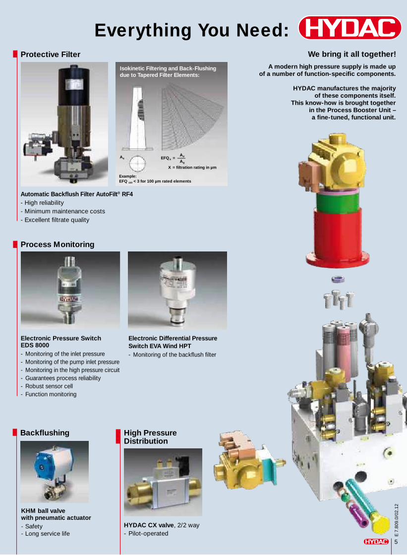
5
E 7
.809
.0/0
2.12
Everything You Need:We bring it all together!
A modern high pressure supply is made up of a number of function-specific components.
HYDAC manufactures the majority of these components itself.
This know-how is brought together in the Process Booster Unit – a fine-tuned, functional unit.
Protective Filter
Automatic Backflush Filter AutoFilt® RF4 - High reliability- Minimum maintenance costs- Excellent filtrate quality
A EA FA E
EFQ X = –
X = filtration rating in μm
Example: EFQ 100 < 3 for 100 μm rated elements
Isokinetic Filtering and Back-Flushing due to Tapered Filter Elements:
Process Monitoring
Electronic Pressure SwitchEDS 8000- Monitoring of the inlet pressure- Monitoring of the pump inlet pressure- Monitoring in the high pressure circuit- Guarantees process reliability- Robust sensor cell- Function monitoring
Electronic Differential Pressure Switch EVA Wind HPT- Monitoring of the backflush filter
Backflushing
KHM ball valve with pneumatic actuator- Safety- Long service life
High Pressure Distribution
HYDAC CX valve, 2/2 way- Pilot-operated
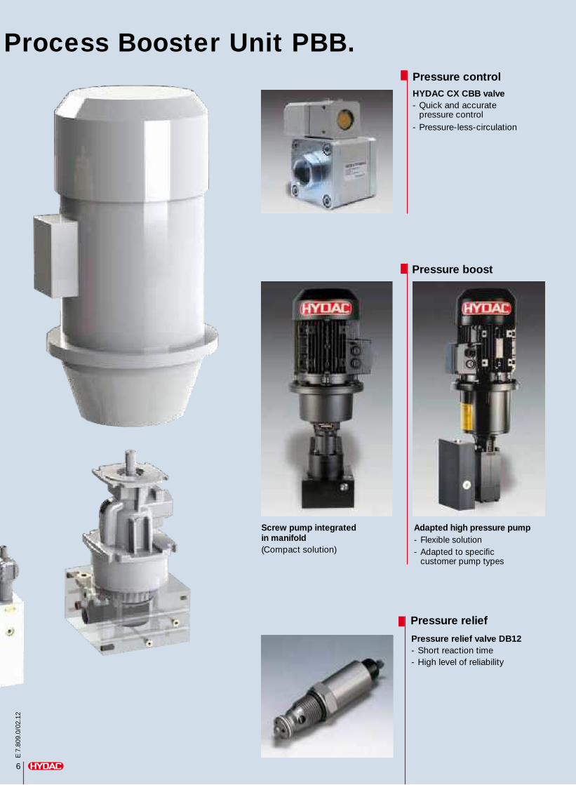
6
E 7
.809
.0/0
2.12
Process Booster Unit PBB.Pressure control
Pressure relief
HYDAC CX CBB valve - Quick and accurate pressure control- Pressure-less-circulation
Pressure relief valve DB12- Short reaction time- High level of reliability
Pressure boost
Screw pump integrated in manifold (Compact solution)
Adapted high pressure pump - Flexible solution- Adapted to specific customer pump types
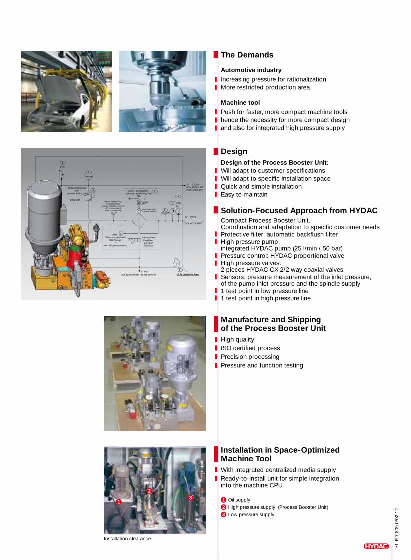
7
E 7
.809
.0/0
2.12
The Demands
Automotive industryIncreasing pressure for rationalizationMore restricted production area
Machine toolPush for faster, more compact machine toolshence the necessity for more compact designand also for integrated high pressure supply
DesignDesign of the Process Booster Unit:Will adapt to customer specificationsWill adapt to specific installation spaceQuick and simple installationEasy to maintain
Solution-Focused Approach from HYDACCompact Process Booster Unit.Coordination and adaptation to specific customer needsProtective filter: automatic backflush filterHigh pressure pump: integrated HYDAC pump (25 l/min / 50 bar)Pressure control: HYDAC proportional valveHigh pressure valves: 2 pieces HYDAC CX 2/2 way coaxial valvesSensors: pressure measurement of the inlet pressure, of the pump inlet pressure and the spindle supply1 test point in low pressure line1 test point in high pressure line
Manufacture and Shipping of the Process Booster UnitHigh qualityISO certified processPrecision processingPressure and function testing
32
1
Installation in Space-Optimized Machine ToolWith integrated centralized media supplyReady-to-install unit for simple integration into the machine CPU
1 Oil supply
2 High pressure supply (Process Booster Unit)
3 Low pressure supply
Installation clearance
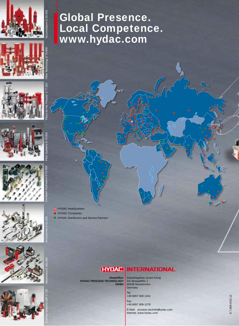
Industriegebiet Grube KönigAm Wrangelflöz 166538 NeunkirchenGermany
Tel: +49 6897 509-1241
Fax: +49 6897 509-1278
E-Mail: [email protected] Internet: www.hydac.com
HeadofficeHYDAC PROCESS TECHNOLOGY
GMBH
E 7
.809
.0/0
2.12
Global Presence.Local Competence.www.hydac.com
HYDAC Headquarters
HYDAC Companies
HYDAC Distributors and Service Partners
Filte
rs fo
r Ind
. Pro
cess
E 7
7.00
0Fi
lter
Sys
tem
s E
79.
000
Com
pac
t H
ydra
ulic
s E
53.
000
Acc
esso
ries
E 6
1.00
0E
lect
roni
cs E
180
.000
Coo
ling
Sys
tem
s D
EF
5.70
0Fi
lter
Tech
nolo
gy E
70.
000
Acc
umul
ator
s E
30.
000