Embed Size (px)
Citation preview

Fluid Filtration
• Equipment
• Methods
• Measurements
www.GEKEngineering.com 1
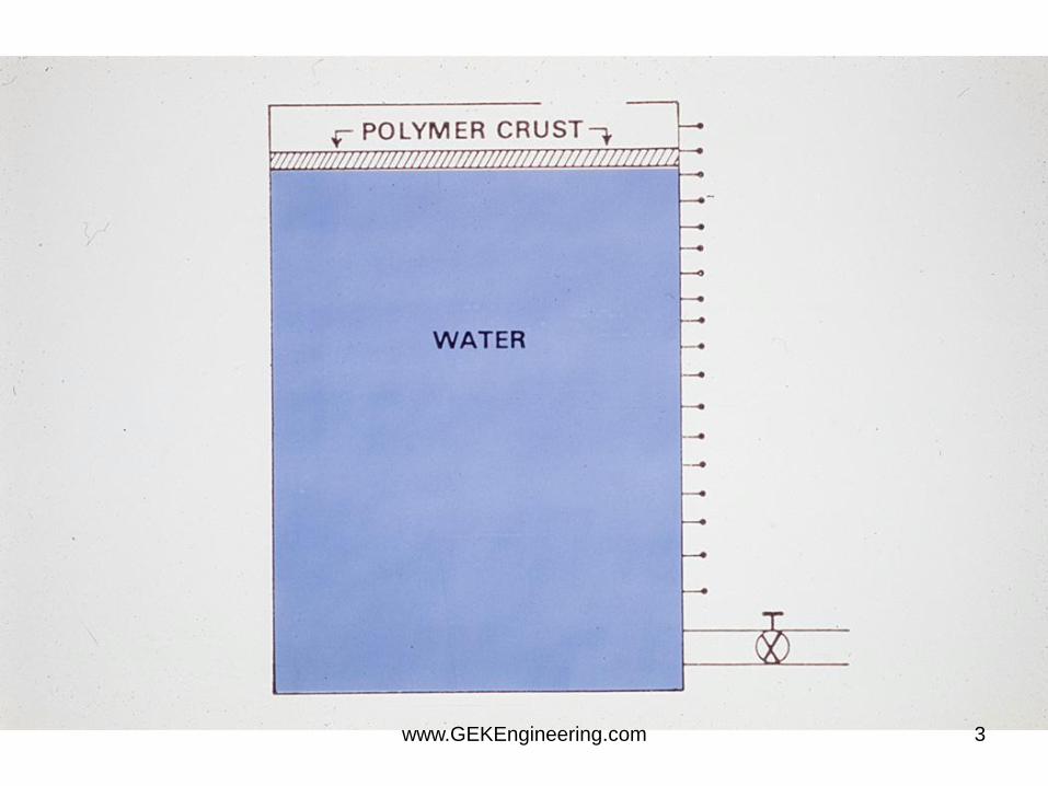
Polymer Damage
• From: muds, pills, frac, carriers
• Stable? - for years
• location - depends on form polymer was in
– dispersed properly - surface to deep in
formation
– in pills and mass - right in perfs
www.GEKEngineering.com 2
www.GEKEngineering.com 3
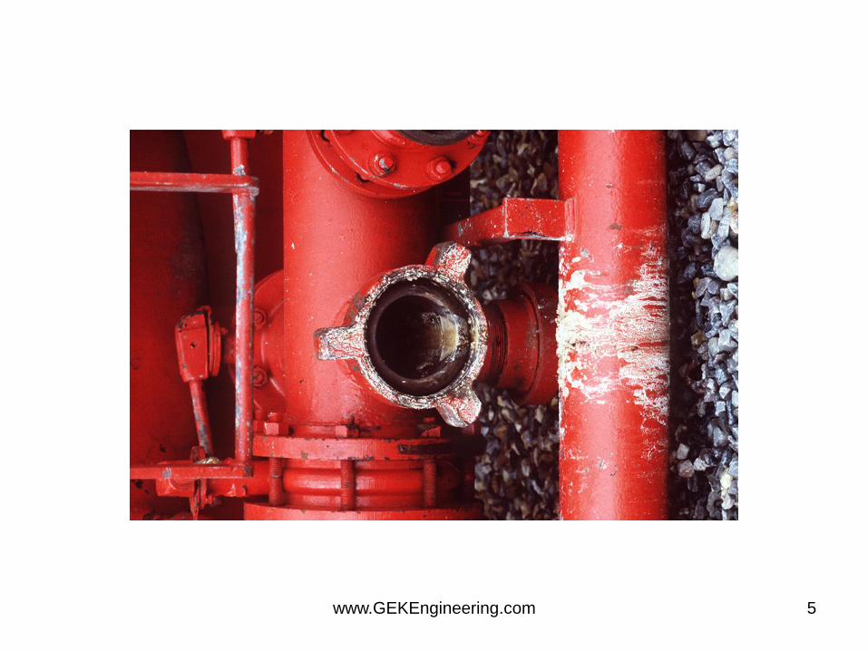
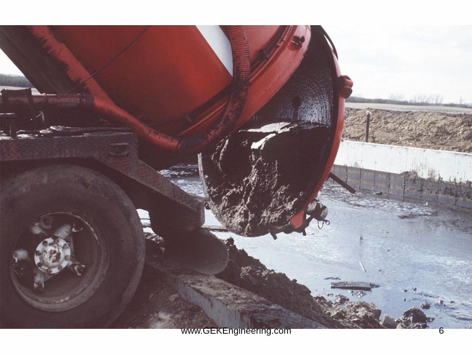
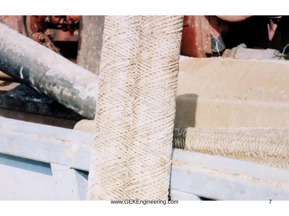
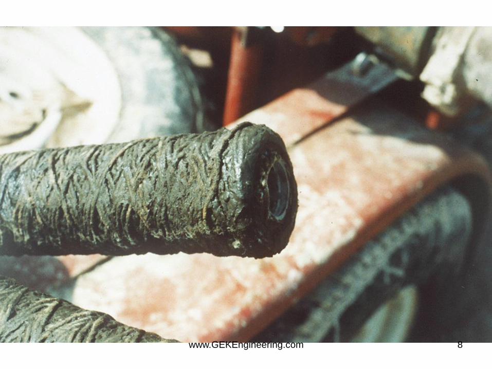
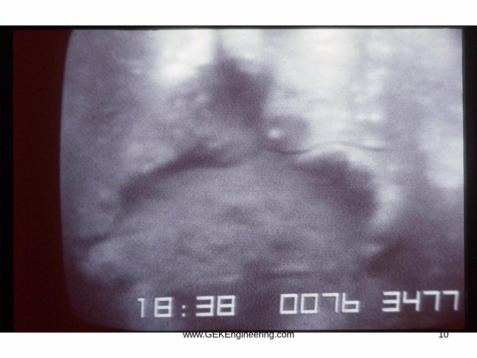
Particles in the Fluid
• Solids from tanks, lines and fluids
• Severe problem, but often ignored
www.GEKEngineering.com 4
www.GEKEngineering.com 5
www.GEKEngineering.com 6
www.GEKEngineering.com 7
www.GEKEngineering.com 8

www.GEKEngineering.com 9
www.GEKEngineering.com 10
Particulate Damage
• Unintended particulates - “dirty fluids”
– filter fluids to 5 microns at Beta of 1000
– maximum NTU of 30, preferable is 20
– clean tanks, lines - how about tubulars?
• Particles in fluid loss pills
– mixed in proper range for perm encountered?
– Will it come off formation? Can it come back
thru pack? Thru screen? What about
removal? www.GEKEngineering.com 11
www.GEKEngineering.com 12
www.GEKEngineering.com 13
www.GEKEngineering.com 14
www.GEKEngineering.com 15
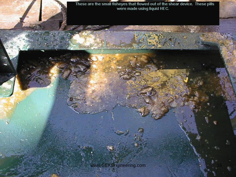
www.GEKEngineering.com 16
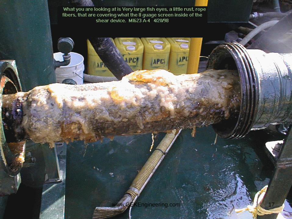
www.GEKEngineering.com 17
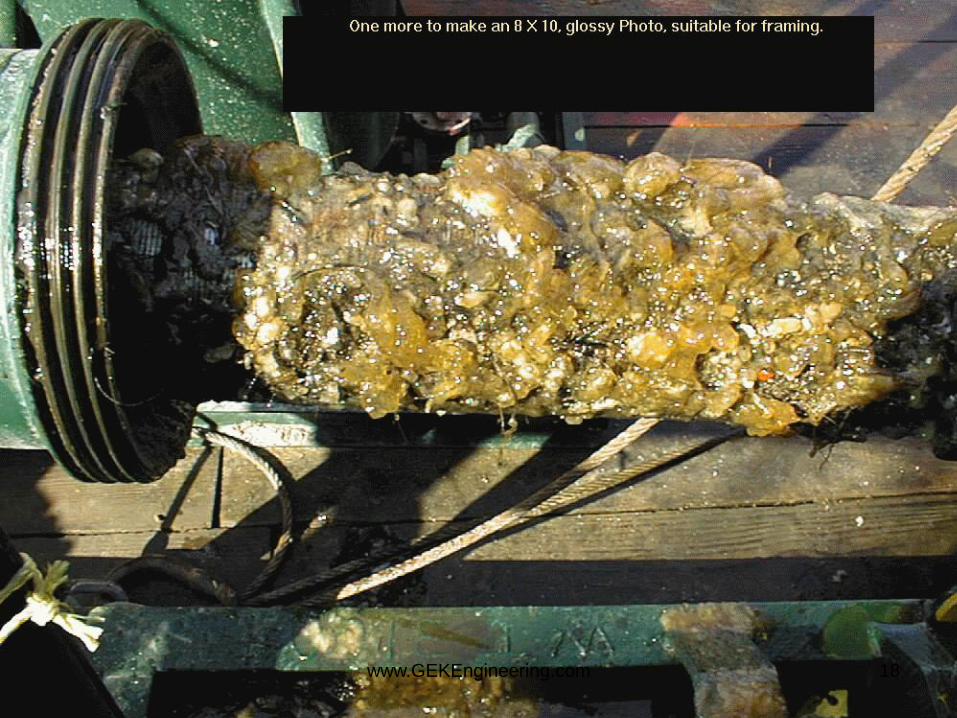
www.GEKEngineering.com 18

Beta Rating
• Beta = number of filter rating and larger
size particles in dirty fluid divided by
number of those particles in clean fluid.
• Beta = 1000/1 = 1000 or 99.99% clean
www.GEKEngineering.com 19
Filters - Operational
• Filters work better at removing solids as
they collect solids – bed filtration is very
effective.
• The filtration efficiency (both size and
quantity removed) improve with use.
• Pressure drop increases with use and is a
measure of filter life.
www.GEKEngineering.com 20

Cartridge Filter Pods
• Have two sets of cartridge filter pods – operate on one while changing filters in the other.
• Set a pressure drop standard to change the filter – depends on cartridge type and pod type.
• Watch dirty fluid discharge – not into the well.
www.GEKEngineering.com 21
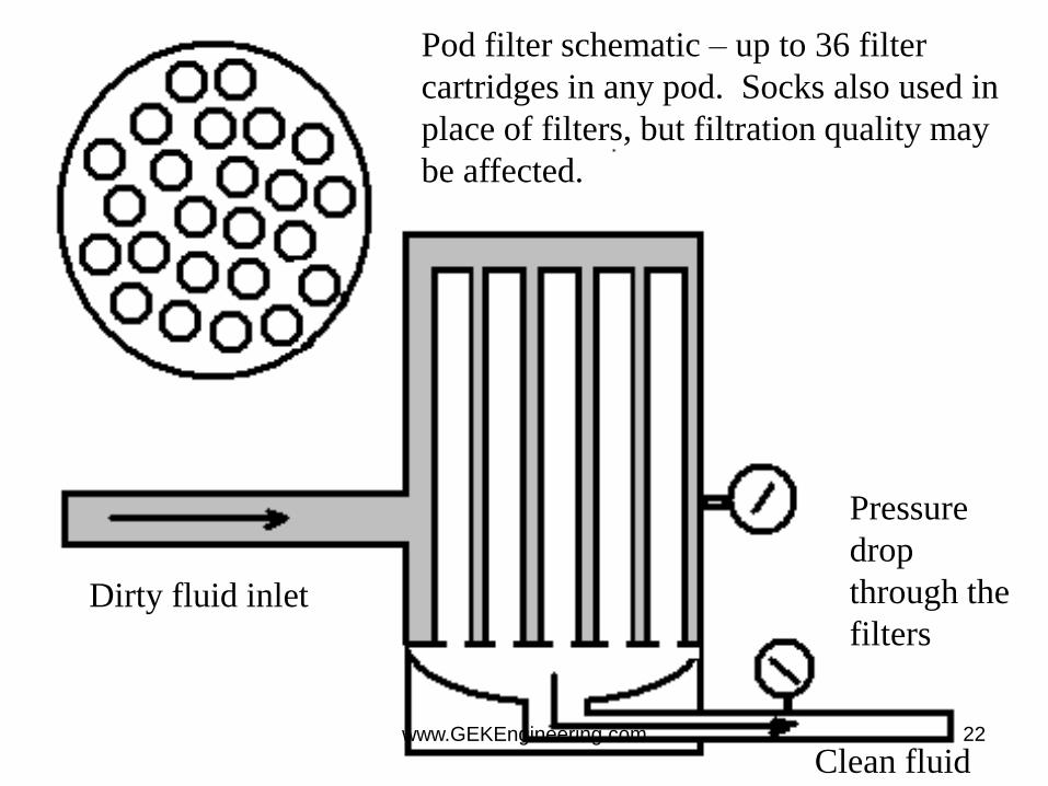
Pressure
drop
through the
filters Dirty fluid inlet
Clean fluid
Pod filter schematic – up to 36 filter
cartridges in any pod. Socks also used in
place of filters, but filtration quality may
be affected.
www.GEKEngineering.com 22
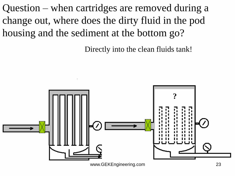
Question – when cartridges are removed during a
change out, where does the dirty fluid in the pod
housing and the sediment at the bottom go?
?
Directly into the clean fluids tank!
www.GEKEngineering.com 23
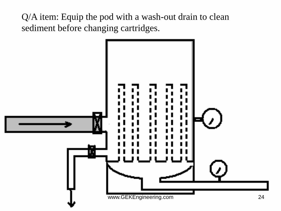
Q/A item: Equip the pod with a wash-out drain to clean
sediment before changing cartridges.
www.GEKEngineering.com 24
Filtration
• Filtration removes solids to prevent build
up of solids and helps prevent plugging in
the formation.
• Two basic filtration systems are employed:
– cartridges (nominal or absolute)
– filter presses (Plate and Frame or Pressure
Leaf)
www.GEKEngineering.com 25
Particulate Damage
• Unintended particulates - “dirty fluids”
– filter fluids to 5 microns at Beta of 1000
– maximum NTU of 30, preferable is 20
– clean tanks, lines - how about tubulars?
• Particles in fluid loss pills
– mixed in proper range for perm encountered?
– Will it come off formation? Can it come back thru pack? Thru screen? What about removal?
www.GEKEngineering.com 26
Filtration and Fluids
• NTU - a turbidity indicator - can be mislead by
natural color of water.
• Nominal filter rating - estimate of the size of
particle removed - don’t trust it.
• Absolute filter rating - size of the holes in the
filter - will change with bed buildup
• Beta rating - a ratio of particles before filtration to
after. A good measure of filter efficiency.
www.GEKEngineering.com 27
Risks and Issues
• Filtration can impact pump rate of completion fluids
• Filtration may be unnecessary cost in some wells, but should be assessed on a well-by-well basis (from potential damage mechanisms
• Filter presses have the advantage of high solids tolerance and throughput - units are large but cheap to operate.
• Cartridges used for small volumes of relatively clean material - smaller throughputs and less tolerance to dirty fluids, generally cartridges are more expensive
• Can be health and environmental risks associated with operating and disposing of filtration medium.
www.GEKEngineering.com 28
Risks and Issues
• NTU (a light transmission test) measurements rely solely on the “cloudiness” of the fluids, corrosion products in return fluids give high values, NTU and solids content are not directly related. Solids content will only assess materials collected at the bottom of the test tube during centrifuging.
• Coloured water will give higher NTU values.
• Using sample sizes of a few mls, it is difficult to draw conclusions about a well with an annular volume of 500 bbl, 0.1% vol/vol solids equates to +/- 1 cuft of solids
deposited for tubing contents of 200 bbl.
www.GEKEngineering.com 29
Determination of Well
Cleanliness • The determination of how clean the well is usually
based on the cleanliness of fluids returning from the wellbore. The most common measures are normal turbidity units (NTU) and solids content, neither relate to what is left in the well.
• Junk baskets, gauge rings and the SPS WellPatroller do give some positive indication of solids removal.
• Other indicators of a clean well are torque and drag (related to the friction coefficient of fluid coating the casing walls) and cleanliness of the clean up string when pulled.
www.GEKEngineering.com 30

Determination of Well
Cleanliness • The determination of how clean the well is usually based on the
cleanliness of fluids returning from the wellbore. The most
common measures are normal turbidity units (NTU) and solids
content, neither relate to what is left in the well.
• Junk baskets, gauge rings and the SPS WellPatroller do give
some positive indication of solids removal.
• Other indicators of a clean well are torque and drag (related to
the friction coefficient of fluid coating the casing walls) and
cleanliness of the clean up string when pulled.
www.GEKEngineering.com 31
Learnings
1. Cartridge units are not usually appropriate for dirty or viscosified fluids
2. DE press materials require good HSE control
3. Tendency is to over-specify filtration requirements.
4. Don’t filter oil with a DE press.
5. Filtration less required when underbalance perforating(?)
6. Kill pills are usually not filtered
7. Absolute cartridge filters are 2-5 times cost of nominal
www.GEKEngineering.com 32

Best Practices
• For general applications, coarse filtration to 80 microns
is all that should be considered when fluids do not
penetrate the formation
• When a fluid penetrates the formation, filtration is more
likely to be required. Filtration should be tailored to the
pore throat size of the formation. A simple guide to
setting a specification is 14% (1/7th) of the average pore
throat diameter
• Filtration below 2 microns is usually impractical
• Always use a guard filter downstream of a DE press
• For a DE press filtration, rate is approximately 1 bpm per
100 sqft for sea water and 0.5 bpm per 100 sqft for a
brine
www.GEKEngineering.com 33

Best Practices, Pt 2
• A solids content of about 0.05% determined by an electric centrifuge
is acceptable for most operations. For gravel packing this should be
reduced to 0.02%.
• To determine solids content the standard tubes for sand content for
the centrifuge are not usually appropriate, centrifuge tubes with
more accurate calibrations should be obtained.
• NTU values should be used to track clean up with regular samples
taken for analysis of solids content at a later date.
• A target value of 50 NTU above surface pits should be used.
• For critical wells e.g. high angle wells/where milling has
occurred/previous problems with debris, a circulating junk basket
(e.g., the SPS WellPatroller is recommended).
www.GEKEngineering.com 34
Best Practices, Pt 3
• Where the string is rotated during clean up the increase in torque can be used as an indicator, the coefficient of friction in sea water/brine is more than twice that of OBM.
• Visual inspection of the clean up string, if it is mud free and water wet mud displacement has been successful, if the string is mud coated run a gauge ring/junk basket or SPS WellPatroller.
• For critical application (e.g. gravel pack) use particle size analysers on location, laser particle size systems are recommended.
www.GEKEngineering.com 35

Measurement Learnings
• To deal with rust color (or precipitation)
interference with NTU readings, add a
small amount of HCl after the first reading
and re-measure.
• If the junk basket is full, rerun.
www.GEKEngineering.com 36
Filtration Considerations
• Very clean fluids have high leakoff rates
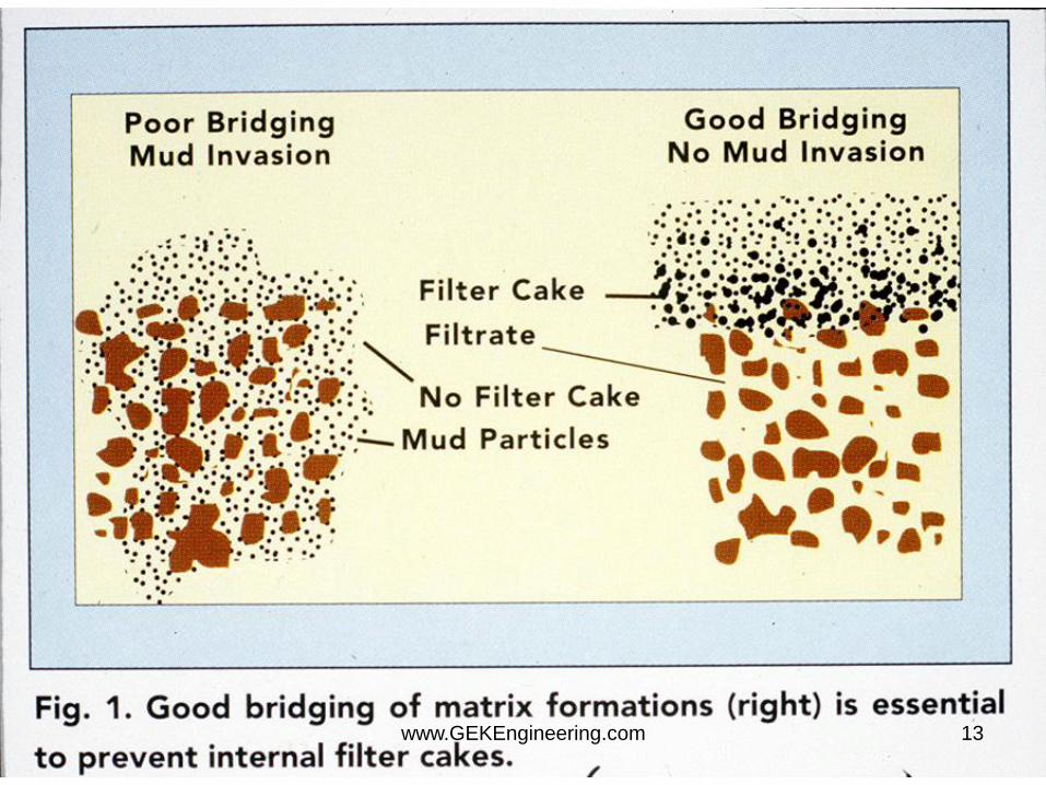
• Fluids with properly blended fluid loss control materials added after filtration have a better chance of cleanup than with the initial particles in the fluid. Particles must be sized to stop at the face of the formation.
• All gelled fluids should be sheared and filtered – even the liquid polymer fluids.
www.GEKEngineering.com 37
Sizing of Filters
• Methods to determine size of pore throats: – Kozeny
– Coberly
– Scanning Electron Microscope
Comments from Ken Troupe of Baker
www.GEKEngineering.com 38

Pore Throat Size- Kozeny
• d= ( D50 )/ (3(1- )) 0.128 (k/)1/2
• where:
d = avg pore throat diam (m)
D50 = avg formation grain diameter (m)
= porosity (fraction)
k = absolute permeability (md)
www.GEKEngineering.com 39

Pore Throat Size - Coberly
• d = D50 / 6.5
• where:
d = average pore throat diameter (m)
D50 = avg formation grain diameter (m)
www.GEKEngineering.com 40
SEM – Pore Throats
• In addition to other methods, pore size
openings can be physically measured by
looking at a formation sample with a
scanning electron microscope.
• Avg pore size determined statistically.
www.GEKEngineering.com 41
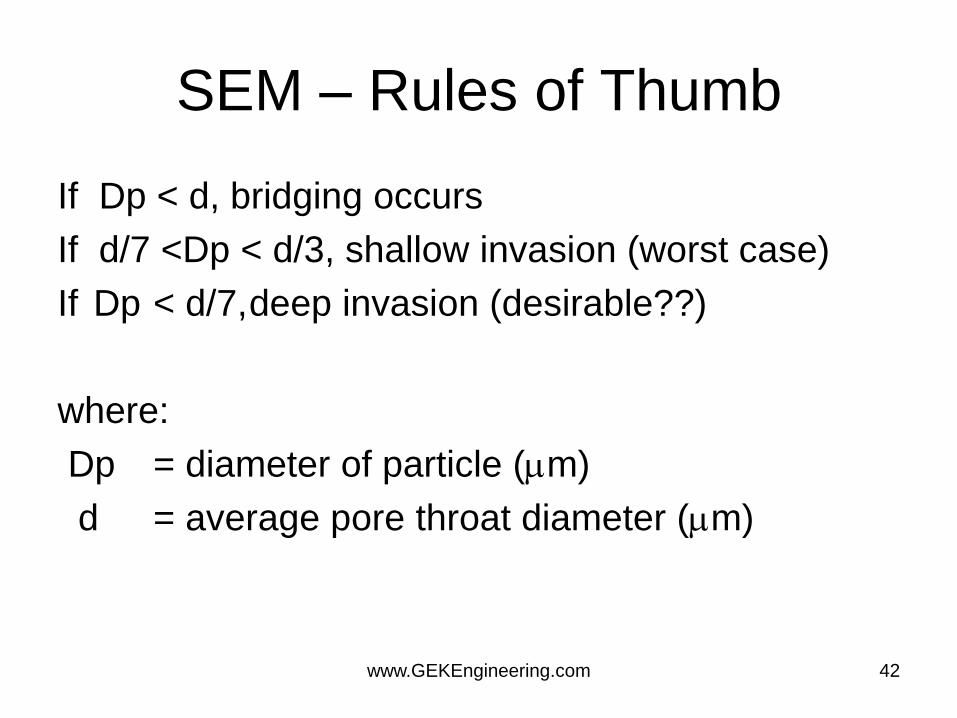
SEM – Rules of Thumb
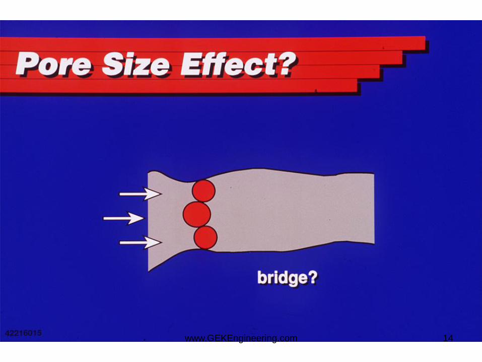
If Dp < d, bridging occurs
If d/7 <Dp < d/3, shallow invasion (worst case)
If Dp < d/7, deep invasion (desirable??)
where:
Dp = diameter of particle (m)
d = average pore throat diameter (m)
www.GEKEngineering.com 42

Particles in the Fluid
• Solids from tanks, lines and fluids
• Severe problem, but often ignored
www.GEKEngineering.com 43
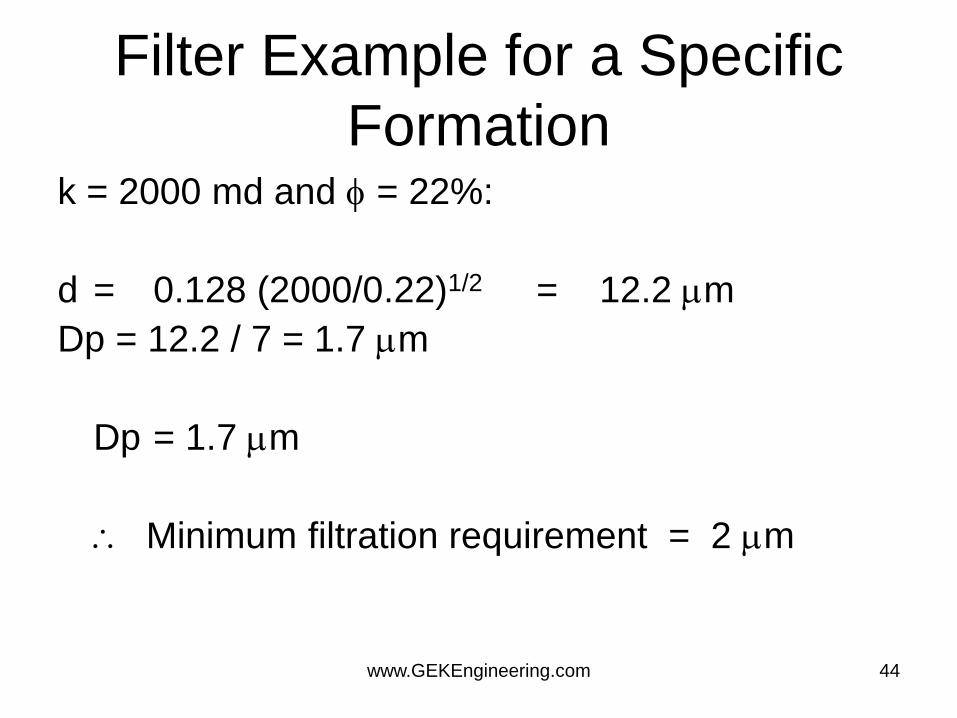
Filter Example for a Specific
Formation k = 2000 md and = 22%:
d = 0.128 (2000/0.22)1/2 = 12.2 m
Dp = 12.2 / 7 = 1.7 m
Dp = 1.7 m
Minimum filtration requirement = 2 m
www.GEKEngineering.com 44
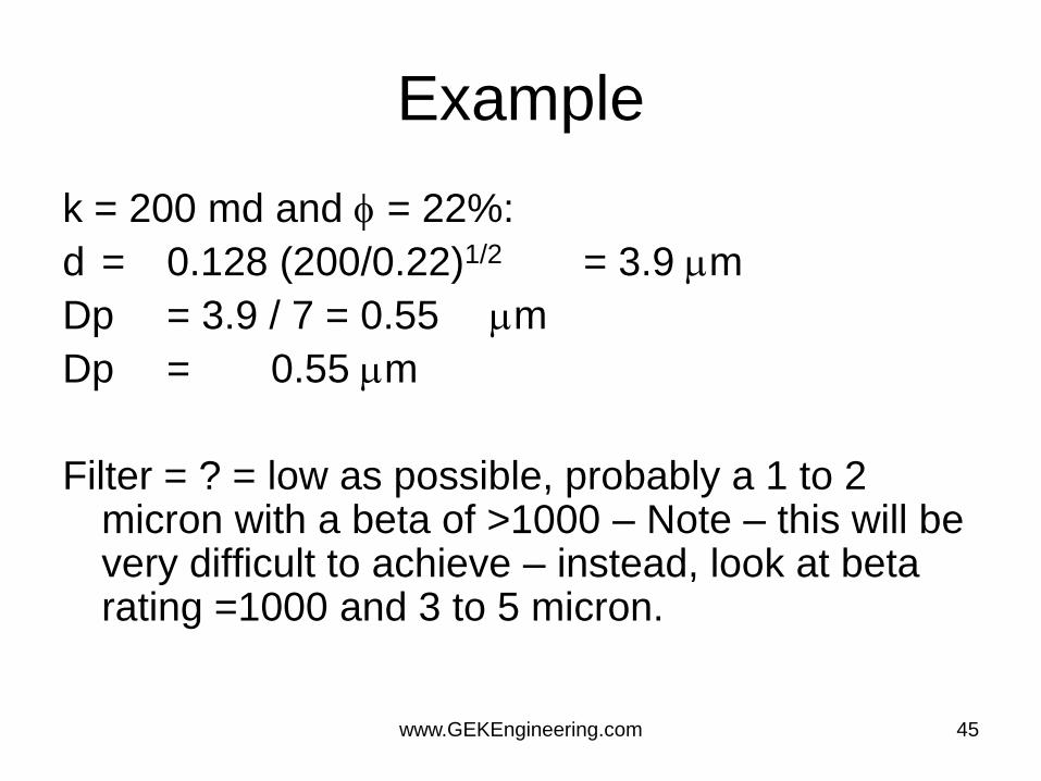
Example
k = 200 md and = 22%:
d = 0.128 (200/0.22)1/2 = 3.9 m
Dp = 3.9 / 7 = 0.55 m
Dp = 0.55 m
Filter = ? = low as possible, probably a 1 to 2 micron with a beta of >1000 – Note – this will be very difficult to achieve – instead, look at beta rating =1000 and 3 to 5 micron.
www.GEKEngineering.com 45
Beta Rating
• Beta = number of filter rating and larger
size particles in dirty fluid divided by
number of those particles in clean fluid.
• Beta = 1000/1 = 1000 or 99.99% clean
www.GEKEngineering.com 46
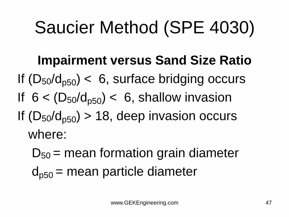
Saucier Method (SPE 4030)
Impairment versus Sand Size Ratio
If (D50/dp50) < 6, surface bridging occurs
If 6 < (D50/dp50) < 6, shallow invasion
If (D50/dp50) > 18, deep invasion occurs
where:
D50 = mean formation grain diameter
dp50 = mean particle diameter
www.GEKEngineering.com 47
Saucier
• Based on Saucier, the largest particle size
in our completion fluid should be less than
D50/18,
• This correlation indicates a much less
stringent filtration requirement than
Kozeny's or Coberly's method.
www.GEKEngineering.com 48

Saucier Formation Example
D50 = 105 micron (control w/ 20/40 Mesh gravel)
Dp = 105/18 = 5.8 m
Minimum filtration requirement = 6 m
www.GEKEngineering.com 49
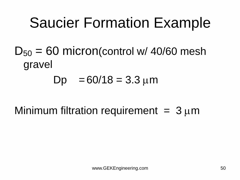
Saucier Formation Example
D50 = 60 micron(control w/ 40/60 mesh
gravel
Dp = 60/18 = 3.3 m
Minimum filtration requirement = 3 m
www.GEKEngineering.com 50

Polymer Damage
• From: muds, pills, frac, carriers
• Stable? - for years
• location - depends on form polymer was in
– dispersed properly - surface to deep in
formation
– in pills and mass - right in perfs
www.GEKEngineering.com 51
Tank/Pit Cleaning
• Use pit washing tools to speed up pit cleaning, reduce pit entry and waste volumes.
• Draft plan including pumping schedules and pit requirements, discuss at toolbox talk with all relevant parties
• Check pit isolation valves to reduce risk of U-tube contamination
www.GEKEngineering.com 52
Areas to Clean:
1. Tanks used for clean fluid and pumping
2. Blender or cement unit and piping to rig floor
3. Kill line
4. Choke and rig floor manifolds
5. Pump bleed over line to pits
6. Shaker area (header box) and sample point
7. Stand pipe and back pressure manifold
8. Degasser tank and unit
9. Reverse lines
10.Flowline where accessible
11.Mixing system
12.Trip Tank
13.Drain lines and drip pans
www.GEKEngineering.com 53
Performance Best Practices
• A brine returns with an NTU < 30 above
value of fluid in pits is excellent
performance
• Clean returns after circulating < 150% of
hole volume is good performance
• Interface volumes between pills of <20 bbl
is excellent performance
www.GEKEngineering.com 54
Risks and Issues
• Filter presses use beds of diatomaceous earth (DE) or
perlite,
– they have the advantage of high solids tolerance and throughput,
units are large but cheap to operate.
– Cartridges should be used where small low volumes of relatively
clean material have to be processed. They have smaller
throughputs than and less tolerance to dirty fluids. Cartridges are
typically more expensive
• There may be HSE risks associated with operating and
disposing of filtration medium (dust, chemical residue,
etc.).
www.GEKEngineering.com 55

Learnings
• Single stage cartridges not appropriate for very dirty or some viscosified fluids
• DE presses present HSE issues.
• Tendency is to over specify filtration specs.
• Do not filter oil with DE.
• If underbalanced perforation is planned, is filtration required?
• Filter kill pills? (solids range more important).
• Absolute cartridges are 2 to 5 x Nominal cost
www.GEKEngineering.com 56
Best Practices
• For general applications, coarse filtration to 80
microns is all that should be considered when
fluids do not penetrate the formation
• When a fluid penetrates the formation filtration is
more likely to be required, it should be tailored to
the pore throat size of the formation.
– A simple guide to setting a specification is 14% (1/7th)
of the average pore throat diameter
www.GEKEngineering.com 57

Best Practices
• Filtration below 2 microns is usually impractical in well operations
• Always use a guard filter downstream of a DE press
• For a DE press filtration rate is approximately 1 bpm per 100 sqft for sea water and 0.5 bpm per 100 sqft for a brine
www.GEKEngineering.com 58
How Clean?
• The determination of how clean the well is usually based on the cleanliness of fluids returning from the wellbore.
• The most common measures are normal turbidity units (NTU) and solids content, neither relate to what is left in the well.
• Also: – junk baskets, gauge rings and recovery systems give some
indication of solids removal.
– torque and drag (related to the friction coefficient of fluid coating the casing walls) and
– cleanliness of the clean up string when pulled.
www.GEKEngineering.com 59
Filter Level
• Minimum filtration criteria
– particles passing through the filter need to be
small enough to freely flow through the
formation without plugging up the critical near
wellbore area.
– filtering should achieve a maximum particle
size in the completion fluid which is less than
the pore diameter divided by 7.
www.GEKEngineering.com 60
Risks and Issues
• Measurement systems:
– NTU: (a light transmission test) measurements rely solely on the “cloudiness” of the fluids. NTU and solids content are not directly related. NTU is affected by color of water, stains, and surfactants. Common limits are 20 to 30 NTU.
– Centrifuging (grindouts/shakeouts) Solids content will only assess materials collected at the bottom of the test tube during centrifuging. These tests use the sample sizes of a few mls and it is difficult to draw conclusions about a well with an annular volume of 500 bbl, 0.1% vol/vol solids equates to +/- 1 cuft of solids deposited for tubing contents of 200 bbl.
www.GEKEngineering.com 61
Learning
• To deal with the problem of free rust (oxidation
of free iron in water) impacting turbidity
readings, a little acid (HCl) should be added
after the initial reading.
• Oxidized fluids (at surface) will precipitate
disolved ferrous iron.
• If the junk basket is pulled full it should be re-
run.
www.GEKEngineering.com 62
Best Practices
• A solids content of >0.05% determined by an
electric centrifuge is acceptable for most
operations. For gravel packing this should be
reduced to 0.02%
• To determine solids content the standard tubes
for sand content for the centrifuge are not
usually appropriate, centrifuge tubes with more
accurate calibrations should be obtained
www.GEKEngineering.com 63

Best Practices
• NTU can be used to track clean up by regular
sampling and later analysis of solids content.
• NTU from the well should be no more than 50
above the source.
• For critical wells e.g. high angle wells/where
milling has occurred/previous problems with
debris, baskets and debris recovery systems are
needed.
www.GEKEngineering.com 64
Best Practices
• Where the string is rotated during clean up the increase in torque can be used as an indicator, the coefficient of friction in sea water/brine is more than twice that of OBM.
• Visual inspection of the clean up string, if it is mud free and water wet mud displacement has been successful, if the string is mud coated run a gauge ring/junk basket
• For critical application (e.g. gravel pack) particle size analysers on location may be useful.
www.GEKEngineering.com 65
Completion Fluid - Checklist
• Is the formation liquid sensitive to liquid relative permeability effects?
• Compatability with formation? (clay and minerals)
• Compatability with formation fluid? (emulsion, sludge, foam, froth)
• Tanks and surface equipment clean?(pumps, lines, hoses, blenders)
• Are polymers breakable? How is breaker added?
• Polymers, hydrated, sheared and filtered? Filter level? Beta rating?
• Minimize the pipe dope?
• Corrosion reactions understood?
• Erosion potential understood?
www.GEKEngineering.com 66

Unwanted Foams
• Foam is an emulsion where gas is the internal phase (mist is an emulsion with gas as external phase).
• Foaming conditions – some oils (ppm conc. of C6-C9organic acids and
alcohols)
– diesel - (particularly bad and varies from lot to lot)
– some acid additives (emulsifiers, salts, inhibitors)
– XCD polymers (and others)
• Look for and destroy the stabilizer to break the foam.
www.GEKEngineering.com 67
Filtration and Cleaning
• Brine and ? (tanks, lines, pumps, etc.)
• Pickle the tubulars?
• NTU or particle count as a measure? How clean is clean? = Avg pore throat x 0.2?
• Beta rating and micron rating important
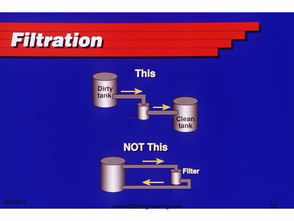
• Tank arrangement when filtering (from dirty tank to clean, not in a loop)
• Filter type – DE or Cartridge (no resin coated cartridges)
www.GEKEngineering.com 68
Filtration Ratings
• NTU - a turbidity indicator - can be mislead by natural color of water. An NTU of 20 to 30 is generally clean.
• Nominal filter rating - estimate of the size of particle removed - don’t trust it. Filtration efficiency improves with bed build-up
• Absolute filter rating - size of the holes in the filter. Filtration efficiency improves with bed build-up
• Beta rating - a ratio of particles before filtration to after. A good measure of filter efficiency.
• Suggestion – use a 5 to 10 micron rating with a beta rating of 1000 for most clear brine applications.
www.GEKEngineering.com 69
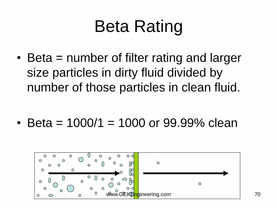
Beta Rating
• Beta = number of filter rating and larger
size particles in dirty fluid divided by
number of those particles in clean fluid.
• Beta = 1000/1 = 1000 or 99.99% clean
www.GEKEngineering.com 70
Equipment Risks and Issues
• Equipment failure may result in additional junk or a stuck clean up string, (not a common problem.
• There have been instances with casing scrapers and brushes where the clean out tool has introduced junk to the hole when these are not of a single piece construction or have retaining mechanisms for blocks.
• Circulating subs (particularly hydraulically operated) carry some risk associated with failing to close thus losing the ability to circulate to the bottom of the well.
• Some of the equipment is only available from niche / specialist suppliers which carries risks around QA/QC and tool availability.
• There is concern with running well clean up tools with minimum by pass area pushing large pieces of junk ahead and into CIV/FIV tools
www.GEKEngineering.com 71
Equipment Learnings
• Conventional casing scrapers with spring actuated
blocks have failed leaving junk in the hole or even a
stuck tool.
• Conventional scrapers are not built for extended
rotation or drilling. Scrapers work in reciprocation.
• Failure rate of multifunction ball opening circulating
subs has been high in some regions.
www.GEKEngineering.com 72

Equipment Learnings
• Weight actuated tools rely on maintaining weight set down on the tool to maintain the circulation path (all circulation is at one point). These tools should be run with the clutch option allowing drillpipe to be rotated independently of the pipe inside the liner. (Rotation assists cleanout)
• Recent experience with the SPS WellPatroller highlighted it is very effective at removing gunk and solids debris, this tool provides a level of assurance not available with any of the other tools (including conventional junk subs).
www.GEKEngineering.com 73
Best Practices and Design
• Casing scrapers should create maximum contact with ID of casing, be a one piece design with full drill pipe strength and no weak internal connections.
• Casing scrapers should enable rotation at rates up to 50 rpm, these should be of a design so that blocks are either retained in the body of the scraper. (UWG/Global) or are an integral design (SPS Razorback).
• The preferred circulating sub should be of the type utilising weight set down to function, with a clutch mechanism. If a reliable hydraulic tool is developed this may become preferable as it allows reciprocation with circulation.
• For clean out strings in high angle cased well a WellPatroller should be run (or if concern about debris or junk in the well).
• Casing brushes are not considered necessary if an effective scraper is selected. If a brush is used it should be redressed after each application.
www.GEKEngineering.com 74
Surface Learnings
• Use pit washing tools to speed up pit cleaning,
reduce pit entry and waste volumes.
• Plan pumping schedules and pit requirements,
• Check pit isolation valves to reduce risk of U-
tube contamination
• Focus clean up work from flow line/shakers
through to the pits.
www.GEKEngineering.com 75

Surface Learnings – Check
Areas • 1. All pits to be used for clean fluid and pumping
• 2. Cement unit to rig floor
• 3. Kill line
• 4. Choke and rig floor manifolds
• 5. Pump bleed over line to pits
• 6. Shaker area (header box) and sample point
• 7. Stand pipe and back pressure manifold
• 8. Degasser tank and unit
• 9. Reverse lines
• 10. Flowline where accessible
• 11. Mixing system
• 12. Trip Tank
• 13. Drain lines and drip pans
www.GEKEngineering.com 76