Embed Size (px)
Citation preview

International Research Journal of Engineering and Technology (IRJET) e-ISSN: 2395-0056
Volume: 07 Issue: 08 | Aug 2020 www.irjet.net p-ISSN: 2395-0072
© 2020, IRJET | Impact Factor value: 7.529 | ISO 9001:2008 Certified Journal | Page 3755
Filtration and Calculation of Current Harmonics in Power Grid with
Simulation Results
Mr.Harshal Yashwant Thakur1
(Student at SRK University Bhopal)
Mr.Vivek Kumar Yadav2
(Professor at SRK University Bhopal)
-----------------------------------------------------------------------***--------------------------------------------------------------------Abstract— Now-a-days because of the advance technology, the demand for wattage is increasing chop-chop in currently. All equipment within the grid would like power constant and endlessly for his or her higher operation and performance. The ability quality depends on various factors like frequency variations, voltage variation, faults and line outages within the system. The performance of the all instrumentation is totally depends on the standard of power that provides to that. The poor power quality reduces the life and potency of the instrumentation of the ability system. To extend the potency of the general system these issues ought to be reduced. Harmonics square measure the most consequence of the ability quality issues. Once these harmonics travel through the system, it results in the heating of the instrumentation, insulation failure and vibrations of motor shaft and thence to scale back these issues harmonics square measure to be filtered. Several filter technologies were developed for this purpose. During this project a shunt active filter is studied. This project additionally presents the fast Power Theory and Adaline based mostly current decomposition to regulate the filter. And also the mentioned management ways were sculptured and simulated in MATLAB. Key words — Pulse Width Modulation (PWM), Switched Mode Power Supply (SMPS), Total Harmonic Distortion (THD), Active Power Filter (APF), Point of Common Coupling (PCC), Voltage Source Converter (VSC), Static Synchronous Compensator (STATCOM), Proportional Integral (PI), Insulated Gate Bipolar Transistor (IGBT) and Proportional Integral Differential (PID). I. INTRODUCTION
Now daily Harmonics within the installation system causes major issue at intervals the instrumental operation of power grid. Power quality of provide is one in each of the large issues at intervals the facility grid. With the increase at intervals the employment of power instrumentality the flexibility quality decreases. Due to the non-linear characteristics they need an inclination to draw harmonics, thus inducement harmonics into the system. If these harmonics travel in line towards the availability they cause over-heating of line, equipment, noise or vibrations. The harmonics as a result of varied problems at intervals
the system like current and voltage distortion, poor power issue, and high order harmonics can cause interference at intervals the close to communication networks. Thus on decrease these problems in installation, whole completely different devices unit of measurement wish to compensate the harmonics. The introduction of non-linear tons of has shown importance to examine regarding the results on the instrumentation at intervals the system. Harmonic have unit of measurement distortion of the provision load current or voltage undulation. The introduction of non-linear load has shown importance to check regarding the results on the instrumentality within the system. The present or voltage will have a non-sinusoidal distorted wave type referable toward the harmonics. Harmonics unit of measurement components of wave type that unit of measurement integral multiple of the basic frequency. The most provide of harmonics in power grid is Power electronic converters like high voltage ac-dc converters, traction drives, wind and star high-powered dc to ac converters and non-linear tons of like SMPS, rectifiers, high efficiency lighting, process instrumentation. Whole completely different techniques were developed to chop back the harmonics. Passive filters were used earlier that unit of measurement replaced by the active filters due to their accountable solid ground and dynamic response.
II. Harmonic Mitigation Techniques
The harmonic mitigation techniques square measure principally line acquisition techniques. These techniques square measure principally used for the development of performance of the system. The most objectives square measure to enhance the P.F., reduction of harmonics and reactive power compensation. Different type of filters measure avails on the market for this purpose. The various filters that square measure on the market square measure divided into 3 sorts. They’re passive filters, active filters and hybrid filters. Every style of filter is once more classified into differing types supported the configuration and operation.
A. Passive filter
It has combination of parallel or series passive parts like resistors, capacitor and reactors. They supply a coffee resistive path for the harmonic carry current which flow

International Research Journal of Engineering and Technology (IRJET) e-ISSN: 2395-0056
Volume: 07 Issue: 08 | Aug 2020 www.irjet.net p-ISSN: 2395-0072
© 2020, IRJET | Impact Factor value: 7.529 | ISO 9001:2008 Certified Journal | Page 3756
through ringing at that individual harmonic current frequency. And passive filters are usually connected in parallel with the connected load for current harmonic mitigation. This passive filter performance is chiefly depends on the ohmic resistance of the system. And passive filters are once more divided into 2 varieties.
1. High Pass Filter
The high pass filter may be a combination of passive
components like electrical device and reactor. It provides a coffee electrical phenomenon path to all or any the harmonic carry currents on top of an explicit frequency. By this the harmonic carry currents on top of this frequency are filtered. The filter order is depends on the quantity of non-active components employed in this filter. Counting on the quantity of components connected they're divided into second order, third order etc. The high pass filter is shown within the Fig.1
Fig.1.High Pass Filter
2. Low Pass Filter
The low pass filter could be a LC circuit. it's tuned to a definite frequency to supply an occasional electrical resistance path thereto harmonic frequency current. These ar typically accustomed filter low order harmonic currents like fifth and seventh order harmonics. These also are accustomed give reactive power issue improvement. The low pass filter is shown within the Fig .
Fig.2.Low Pass Filter
Even though the passive filters square measure easier to style and low initial value there measure some disadvantages. The passive filters measure designed to get rid of sure harmonics, if any extra harmonics square measure introduced the filter has got to be redesigned. At sure hundreds passive filters could cause resonance that results in voltage fluctuations. In passive filters unbalanced load conditions and neutral shifting cannot be resolved. Due to the drawbacks, the passive filers cannot offer economical operation in improvement of power quality of the system. Active filters were developed to beat the drawbacks of the passive filters. B. Active Filters
Due to the dynamic response of the active filters they
will be want to eliminate current harmonics quicker than passive filter. They will even be used for reactive power compensation and voltage distortions. PWM techniques are often wont to take away unbalanced load and neutral shifting issues. Active filters area unit combination of active and passive components. Active filter could be a voltage supply device that provides compensating currents or voltages supported its configuration. Active filters encompass a device with energy storage component usually a passive component. The device converts the ability from the storage component to provide necessary harmonic current to load whereas charging and discharging of the component. And support the operation and configuration of the active filters area unit classified into 3 sorts.
1. Series active filter
Series APFs are connected nonparallel with the line
through an electrical device i.e. transformer. It acts as a voltage supply injecting voltage nonparallel with the provision voltage. It’s wont to compensate the ability quality issues like voltage swag and voltage swell. The circuit diagram of the series APF is shown within the Fig.3
Fig.3.Series Active Filter Circuit Diagram
2. Shunt active filter The VSI primarily based shunt Active Filter is
generally used. It’s connected in parallel to the load. Shunt active filter is employed to current harmonics mitigation,

International Research Journal of Engineering and Technology (IRJET) e-ISSN: 2395-0056
Volume: 07 Issue: 08 | Aug 2020 www.irjet.net p-ISSN: 2395-0072
© 2020, IRJET | Impact Factor value: 7.529 | ISO 9001:2008 Certified Journal | Page 3757
reactive power compensation and power factor correction. It acts as a current supply injecting current harmonics with opposite phase into the line. The circuit diagram is shown within the Fig.4.
Fig.4.Shunt Active Filter Circuit Diagram
The active filters have several benefits over passive filters. Single active filter may be accustomed eliminate totally different harmonics at a time. They will even be used for reactive power compensation. Performance of the filter changes with the load variations and thanks to such benefits active filters area unit most preferred. III. SHUNT ACTIVE FILTER AND its CONTROL STRATEGIES.
The harmonics square measure quenched by
mistreatment completely different filters like passive filters, active filters and hybrid filters. The Shunt Active Filter is employed for the harmonic currents and therefore the reactive power compensation. Shunt APF consists of a 3 phase VSI with a capacitance that acts as a voltage controlled current supply. For the APF to compensate harmonics, reference currents need to be extracted from the load currents. That reference currents measure given to the controller for generation of pulses for the switches within the electrical converter. Completely different theories square measure out there to extract the reference currents. During this project solely fast power theory and Adaline primarily based decomposer that could be a neural network square measure used for the extraction of reference current. Within the adaline primarily based decomposer the load current is rotten into basic positive sequence part, basic negative sequence part and harmonic parts. The harmonic currents square measure used for harmonic compensation. Reactive current and negative sequence parts square measure used for reactive power compensation and unbalanced load. And within the fast power theory the load voltages and currents square measure regenerate into 2 phase quantities and therefore the power square measure calculated. The periodic parts of the active power, reactive power square measure taken for the reference current generation in 2 phase. Then the 2 phase measure regenerate into 3 phases and therefore the pulses square measure generated for the switches within the electrical converter.
1. Shunt Active Filter The shunt APF is connected in parallel with the non-linear load to note the harmonics and inject the compensating currents into the system. The compensating currents contain negative harmonic currents and can be reactive
current half looking forward to the compensation. Shunt active filters are used for every and each harmonic and reactive power compensation. Shunt APF consists of a DC link static power converter Associate in nursing energy storage half acts as current offer to produce the compensating currents. The compensation principle for the shunt APF is that the VSI is controlled to inject the compensation currents into the system. The management is based on the reference currents calculated by management ways enforced. Usually this can be often done by estimating the harmonics and thus the shunt APF acts as a current offer injecting harmonics of same magnitude but phase shifted by 180 degree. The filter is operated in such the approach that the availability provides exclusively the fundamental current and thus the filter provides the harmonic currents to the system.
a. DC Side Capacitor Because of the charging and discharging of the electrical condenser ripple voltage can occur on the DC aspect of the electrical converter. Thanks to the charging and discharging of the electrical condenser ripple voltage can occur on the DC aspect of the electrical converter. Variations in load or disturbances in system causes imbalance of real power within the system, so as to take care of the balance the electrical condenser provides the additional power required by the system. The height current drawn from the supply for charging of electrical condenser is adjusted in proportional to the active power.
b. Converter of shunt active filter
Generally an electrical condenser used as Associate in nursing energy memory device that acts a voltage supply. During this topology, dc voltage from the electrical condenser is born-again into Associate in Nursing AC voltage by fittingly gating the facility semiconductor switches.
Fig.5. Voltage Source Converter for Active Power Filters
VSCs square measure most popular over CSCs attributable to their higher potency and lower initial value. The most advantage of VSCs is that they are connected in parallel.

International Research Journal of Engineering and Technology (IRJET) e-ISSN: 2395-0056
Volume: 07 Issue: 08 | Aug 2020 www.irjet.net p-ISSN: 2395-0072
© 2020, IRJET | Impact Factor value: 7.529 | ISO 9001:2008 Certified Journal | Page 3758
c. Control Strategies The different theories for estimation square measure p-q theory, changed p-q theory, id-iq theory, and SRF theory, ripple remodel etc. By the id-iq technique each harmonic current and also the basic negative sequence current square measure paid. Because of the load unbalanced condition the negative sequence part is obtained. Therefore, the system may be used as a harmonic and unbalanced current compensator. In p-q theory 3 phase load voltages and currents of 3 phase arrangement square measure remodeled into 2 phase quantities of orthogonal arrangement. The compensating currents square measure calculated from the fast powers. The fast active and reactive power is calculated from the orthogonal elements. By this technique reactive power compensation may be done even while not sensing the facility absorbed by the load. The reactive current part may be used for reactive power compensation. And Fuzzy logic system relies on formal logic, a system that is additional natural than the foremost systems. It has several benefits than the opposite controllers. It may be used for non-linearity applications and general inputs.
2. Instantaneous Reactive Power Theory Instantaneous Power Theory could be a time domain technique to analyses energy flow. This theory may be used each in steady state and transient state. This theory may be applied to three-phase system three wire and four wire systems. The essential principle of p-q theory is to rework 3 phase load voltages and currents into 2 phase quantities then the fast powers are calculated from the 2 phase quantities. The reference currents are calculated victimization these fast powers. The 3 part load voltages and currents of 3 phase rotating arrangement are reworked into 2 phase elements of orthogonal arrangement by Clarke’s transformation as below.
[
] [
] [
] ….……. (1)
[
] [
] [
] ………… (2)
Where Va, Vb, Vc and Ia, Ib, Ic represent the phase voltages and currents respectively. The total three phase power can be calculated as 𝑃3∅ = . = + + = + + ….. (3)
𝑃3∅ = 𝑝 + 𝑝 …. (4)
Where p is real power in the α–axis & β-axis and po is the zero sequence power. The reactive power can be calculated as 𝑞 = − ……… (5)
Instantaneous real power p, provides the entire power that's being equipped from supply to load at any instant. The fast reactive power is taken as zero, as a result of it's shared between the phases. The zero sequence elements may be used for unbalanced load conditions.
By separating the active and reactive components of current,
[
]
{[
] [𝑝 ] [
] [ 𝑝] }
[
] [
] …… (6)
The real power p is rotten is rotten into 𝑝 that is norm associate degreed an alternating part.
𝑝 = 𝑝 + 𝑝 and 𝑞 = 𝑞 + 𝑞
The alternating element of the important power is especially thanks to voltage and current harmonics gift within the line that should be remunerated. For the reactive power compensation total reactive power q that is calculated should be remunerated.
a. Compensation Strategy
The periodical element of the important power is calculated by filtering the dc element by a filter and subtracting it from the full power or it will acquire directly filtering the important power signal by a high pass filter.
Fig.6. Compensation Strategy of Instantaneous Power
Theory
The compensating currents in three phases are calculated from the two phase reference currents using inverse Clarke transformation.
[
] √
[
]
[
] …….. (7)
3. Adaline Network
This network was unreal by Claude Bernard Widrow and the guy Ted Hoff in 1960. The name Adaline comes from accommodative linear nerve cell. Adaline could be a single layer network with multiple inputs and one output. The
International Research Journal of Engineering and Technology (IRJET) e-ISSN: 2395-0056
Volume: 07 Issue: 08 | Aug 2020 www.irjet.net p-ISSN: 2395-0072
© 2020, IRJET | Impact Factor value: 7.529 | ISO 9001:2008 Certified Journal | Page 3759
output obtained is more established gone through an activation operate typically a linear activation operate.
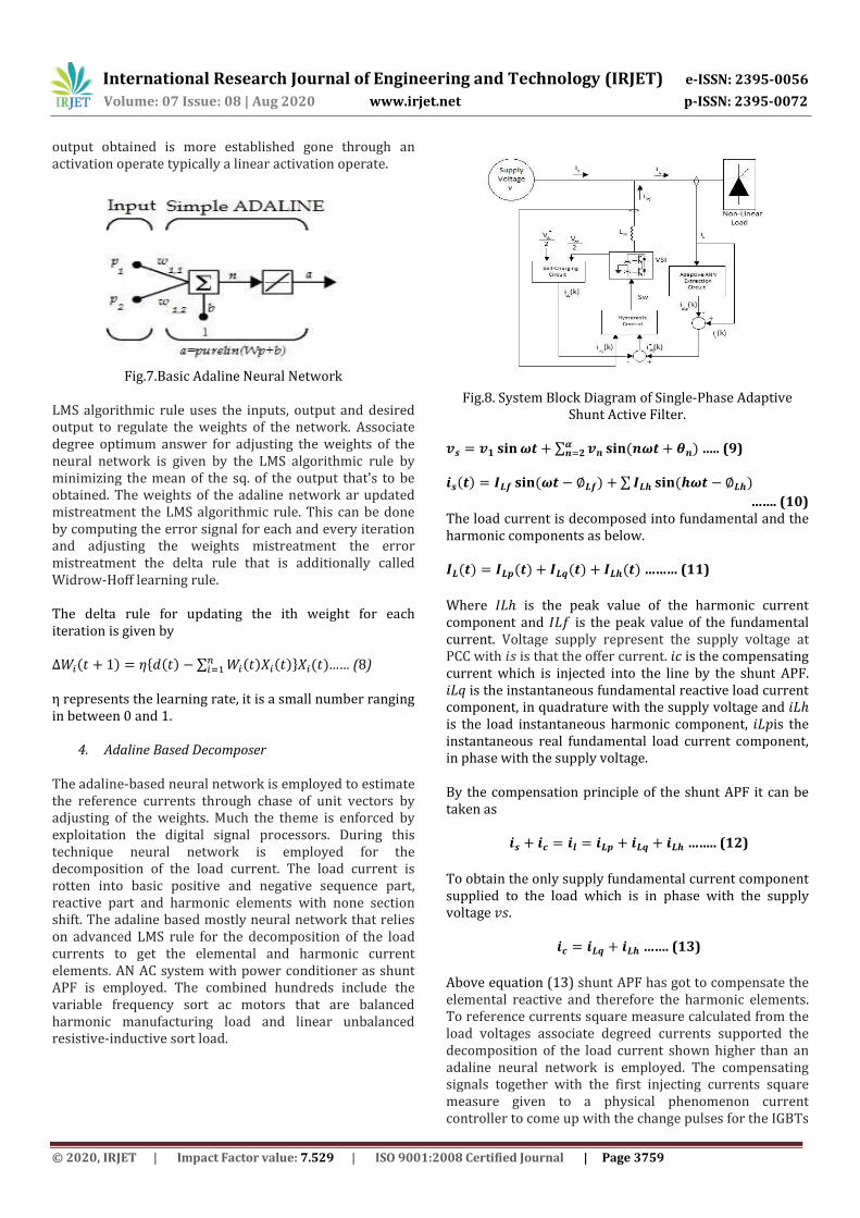
Fig.7.Basic Adaline Neural Network
LMS algorithmic rule uses the inputs, output and desired output to regulate the weights of the network. Associate degree optimum answer for adjusting the weights of the neural network is given by the LMS algorithmic rule by minimizing the mean of the sq. of the output that's to be obtained. The weights of the adaline network ar updated mistreatment the LMS algorithmic rule. This can be done by computing the error signal for each and every iteration and adjusting the weights mistreatment the error mistreatment the delta rule that is additionally called Widrow-Hoff learning rule. The delta rule for updating the ith weight for each iteration is given by { ∑
} …… (8)
η represents the learning rate, it is a small number ranging in between 0 and 1.
4. Adaline Based Decomposer The adaline-based neural network is employed to estimate the reference currents through chase of unit vectors by adjusting of the weights. Much the theme is enforced by exploitation the digital signal processors. During this technique neural network is employed for the decomposition of the load current. The load current is rotten into basic positive and negative sequence part, reactive part and harmonic elements with none section shift. The adaline based mostly neural network that relies on advanced LMS rule for the decomposition of the load currents to get the elemental and harmonic current elements. AN AC system with power conditioner as shunt APF is employed. The combined hundreds include the variable frequency sort ac motors that are balanced harmonic manufacturing load and linear unbalanced resistive-inductive sort load.
Fig.8. System Block Diagram of Single-Phase Adaptive
Shunt Active Filter.
∑ ….. (9)
∑
……. (10) The load current is decomposed into fundamental and the harmonic components as below. ……… (11)
Where 𝐿ℎ is the peak value of the harmonic current component and 𝐿𝑓 is the peak value of the fundamental current. Voltage supply represent the supply voltage at PCC with 𝑖𝑠 is that the offer current. 𝑖 is the compensating current which is injected into the line by the shunt APF. 𝑖𝐿𝑞 is the instantaneous fundamental reactive load current component, in quadrature with the supply voltage and 𝑖𝐿ℎ is the load instantaneous harmonic component, 𝑖𝐿𝑝is the instantaneous real fundamental load current component, in phase with the supply voltage. By the compensation principle of the shunt APF it can be taken as
…….. (12)
To obtain the only supply fundamental current component supplied to the load which is in phase with the supply voltage 𝑣𝑠.
……. (13)
Above equation (13) shunt APF has got to compensate the elemental reactive and therefore the harmonic elements. To reference currents square measure calculated from the load voltages associate degreed currents supported the decomposition of the load current shown higher than an adaline neural network is employed. The compensating signals together with the first injecting currents square measure given to a physical phenomenon current controller to come up with the change pulses for the IGBTs

International Research Journal of Engineering and Technology (IRJET) e-ISSN: 2395-0056
Volume: 07 Issue: 08 | Aug 2020 www.irjet.net p-ISSN: 2395-0072
© 2020, IRJET | Impact Factor value: 7.529 | ISO 9001:2008 Certified Journal | Page 3760
or switches within the electrical converter to supply the specified currents.
5. Hysteresis Current Control The pulses are generated by passing the present error signal to the hysteric phenomenon band. The pulses generated are given to the active filter to provide needed compensating currents that follow the reference currents that are calculated. Hysteric phenomenon current management produces gating pulses to the switches within the electrical converter. This methodology offers associate asynchronous management of the electrical converter switches. The most blessings of this methodology are its lustiness and dynamic action.
Fig.11. Hysteresis Controller Control Logic
There square measure 2 limits within the hysteresis band, the higher band and therefore the lower band. The higher and lower band constitutes the full information measure of the hysteresis management. Once the error current tends to exceed the higher band the higher switch is turned off and therefore the lower switch is turned on within the several branch. By this the present once more tracks back to the hysteresis band. Once the current tend to exceed the lower band limit the higher switch is turned on and therefore the lower switch is turned off. By this switch the present tends to put inside the hysteresis band and compensating current follows the reference current. And that we get result that smaller the bandwidth, higher the accuracy. The voltage wave successively depends on the current error signal of hysteresis management by that the pulses square measure made. Variable frequency is obtained from the physical phenomenon current controller. By dynamical the hysteresis phenomenon band the frequency will be modified. Switching frequency will be obtained from the voltage wave of the electrical converter. IV. SIMULATION RESULTS
As we discussed by using MATLAB we simulate three-phase Non-Linear Load and Combination of Non-Linear Load and Linear Load and simulation results are presented for both the load conditions and the performance of the filter by the two control strategies is compared.
1. Simulation Results with Combination of Non-Linear Load and Unbalanced Linear Load
The performance of the system with Combination of Non-Linear Load and Unbalanced Linear Load is analyzed by simulating the shunt APF filtering using both the control strategies. The system data with 220 V. voltage, 50 Hz frequency, Ls is 4.3 mH. The discussed control strategies are simulated and the circuit diagrams with Combination of Non-Linear Load and Unbalanced Linear Load is shown in fig.12.
Fig.12. Shunt Active Filter Simulation Circuit Diagram
Here the phase-a source current before
compensation is shown in the Fig.13 and the harmonic analysis is shown in the Fig. 14.
Fig.13. current before compensation
Fig.14. Harmonic analysis before compensation
The THD of source current before compensation for the combination of loads is high i.e. 14.23%. After doing simulation by using compensation strategies i.e. p-q theory source current shows in Fig.15. And harmonic analysis of phase current shows in Fig.16

International Research Journal of Engineering and Technology (IRJET) e-ISSN: 2395-0056
Volume: 07 Issue: 08 | Aug 2020 www.irjet.net p-ISSN: 2395-0072
© 2020, IRJET | Impact Factor value: 7.529 | ISO 9001:2008 Certified Journal | Page 3761
Fig.15. current after compensation
Fig.16. Harmonic analysis after compensation By using p-q theory control strategy the THD of the source current for the combination of load is reduced to 3.22% as shown in Fig.16. The simulation is also done using the Adaline based decomposer and the phase a source current after compensation is shown in the Fig.17 and the harmonic analysis is shown in the Fig.18.
Fig.17 current after compensation using Adaline theory
Fig.18 Harmonic analysis after compensation using Adaline theory.
The THD of phase-a source current for the combination of non-linear and linear load is further reduced to 2.63% which is better than the p-q theory. And THD values for all phase current is compare by using p-q theory and Adaline base theory for non linear load is as follows.
Table .1.Comparison of THD values for combination of Non-Linear Load and unbalance linear load.
Phase Without compensation
(%)
Compensation using Adaline
Based Decomposer
(%)
Compensation using
p-q theory
(%) a 18.23
2.48 3.37
b 18.23 2.49 3.35
c 18.23 2.47 3.34
.And when simulate only nonlinear load with this control
strategies the we get different THD values for only nonlinear load as shown in table number 2.
Table .2.Comparison of THD values for Non-Linear Load.
Phase
Without compensat
ion (%)
Compensation using Adaline Based
Decomposer (%)
Compensation using
p-q theory (%)
a 21.13
2.69 3.37
b 21.13 2.66 3.35
c 21.13 2.67 3.34
The results show that the Adaline based current decomposer is better at compensating the harmonics than the traditional p-q theory. V. Conclusion
The power quality downside became the foremost
vital issue within the facility. By reduction of harmonics and power factor improvement the ability quality issues are often reduced. During this project reduction of harmonics by exploitation APF is mentioned. And that we get conclusion that because of the harmonics created by the non-linear load the voltage at the PCC that is additionally non-linear affects the opposite load connected at the PCC. The load current harmonics are paid by injecting negative compensating currents into the line by a filter. The APF is managementled supported 2 control methods; p-q theory and Adaline based mostly decomposer to compensate the load current harmonics. The simulation is additionally allotted with combination of non-linear load and unbalanced linear load and located that APF filters the harmonics and improve the system performance. Results show that Adaline based mostly decomposer management strategy is effective in compensating the harmonics than the normal p-q theory even with unbalanced load. It’s finished that the APF with

International Research Journal of Engineering and Technology (IRJET) e-ISSN: 2395-0056
Volume: 07 Issue: 08 | Aug 2020 www.irjet.net p-ISSN: 2395-0072
© 2020, IRJET | Impact Factor value: 7.529 | ISO 9001:2008 Certified Journal | Page 3762
Adaline based decomposer is healthier than the p-q theory that could be a possible resolution for compensating current harmonics in distribution system. References
[1]. María Isabel Milanés Montero, Enrique Romero
Cadaval, and Fermín Barrero González, “Comparison of Control Strategies for Shunt Active Power Filters in Three-Phase Four-Wire Systems”, IEEE Transactions
on Power Electronics, Vol. 22, No.1, January 2007. [2]. Neethu Sathyan, Fossy Mary Chacko, “DSTATCO
Mmplemented on a 3-Phase 4 Wire Distribution System for Harmonic Elemination and System Balance”, IJAREEIE, Vol.3, Special Issue 5, Dec 2014.
[3]. K. Poongothai, A. Snethil Kumar, Dr. P Ajay-D-Vimal Raj, “Improvement of Power Quality Using Shunt Active Filterby Neural Network Learning Algorithm Technique”, IJRASET, Vol.3, Issue-II, Feb 2015.
[4]. S. Janpony, K. L. Areerak, and K. N. Areerak, “A Literature Survey on Neural Network Applications for Shunt Active Power Filters”, World Academy of Science, Engineering and Technology, Vol.5, 2011-12-21.
[5]. Zenfeng Xiao, Yilong Chen, Qin Li, Xiofend Dao, “Learning and Adaptive Linear Neural Network for enhancing harmonics Compensation”, Proceedings of the 2013 International Conference on Appllied Mathematics and Computational Methods in Engineering.
[6]. D.Gowthami, S.Ravindra, A.Mallikarjuna Prasad, and G, Kishore, “A Novel MATLAB Model of ANN Based Controllers to Improve the Dynamic Response of Shunt Active Power Filter”, IJEEE, ISSN (Print): 2231-5284, Vol.2, Iss 2,3,4, 2012.
[7]. L. H. Tey, P. L. So, Y.C. Chu, “Improvement of Power Quality Using Adaptive Shunt Active Filter”, IEEE Transactions on Industrial Electronics, Vol. 20, No.2, April 2005.
[8]. Sushil Karvekar, Aditi Kumbhojkar, “Comparison of Different Methods of Reference Current Generation for Shunt Active Power Filter under Balanced and Unbalanced Load Conditions”, International Conference on Circuits, Power and Computing Technologies (ICCPCT), 2013.
[9]. Mauricio Aredes and Edson H. Watanabel, “New Control Algorithms for Series and Shunt Three-phase four-wire Active Power Filters”, IEEE Transactions on Power Delivery, Vol. 10, No. 3, July 1995.