Embed Size (px)
Citation preview
Eng. Mohammed Hammouda Electric Circuits II LAB (EELE2111) Eng. Haya Ashraf Swedan
1 | P a g e
Experiment 8
Filters
Objectives: - To study the filter concept and its functions
- To know and study types of Active Filters
- To be able to design and dealing with Active filters
Theory :
Filters are an electric circuit that can control the input signals depending on its frequencies the
circuit can allow it to pass or block it. That means any filter has two cases (frequency regions),
case for allowing to pass wanted signals and the other for blocking unwanted signals.
Filters can be divided into two distinct types: active filters and passive filters. Active filters
contain amplifying devices to increase signal strength while passive do not contain amplifying
devices to strengthen the signal. As there are two passive components within a passive filter
design the output signal has a smaller amplitude than its corresponding input signal, therefore
passive RC filters attenuate the signal and have a gain of less than one, (unity).
Passive filters are made up of passive components such as resistors, capacitors and inductors and
have no amplifying elements (transistors, op-amps, etc) so have no signal gain, therefore their
output level is always less than the input.
Filters are so named according to the frequency range of signals that they allow to pass through
them, while blocking or “attenuating” the rest. The most commonly used filter designs are the:
Low Pass Filter : the low pass filter only allows low frequency signals from 0Hz to its
cut-off frequency, ƒc point to pass while blocking those any higher.
High Pass Filter : the high pass filter only allows high frequency signals from its cut-off
frequency, ƒc point and higher to infinity to pass through while blocking those any lower.
Band Pass Filter : the band pass filter allows signals falling within a certain frequency
band setup between two points to pass through while blocking both the lower and higher
frequencies either side of this frequency band.
Band Reject(Stop) Filter: the band reject filter blocking signals falling within a certain
frequency band setup between two points to pass through while allow both the lower and
higher frequencies either side of this frequency band.
Eng. Mohammed Hammouda Electric Circuits II LAB (EELE2111) Eng. Haya Ashraf Swedan
2 | P a g e
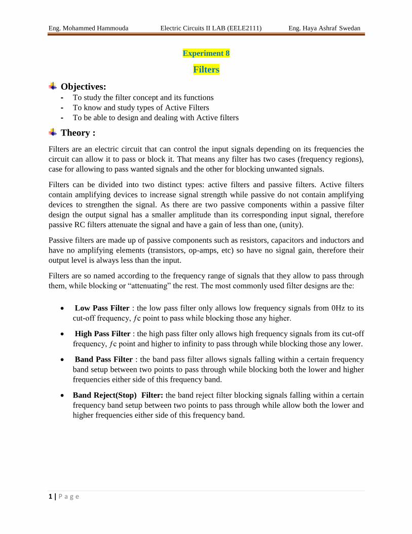
As the function of any filter is to allow signals of a given band of frequencies to pass unaltered
while attenuating or weakening all others that are not wanted, we can define the amplitude
response characteristics of an ideal filter by using an ideal frequency response curve of the four
basic filter types as shown.
Figure 1 Ideal Filter Response Curves
The Low Pass Filter
A Low Pass Filter is a circuit that can be designed to modify, reshape or reject all unwanted high
frequencies of an electrical signal and accept or pass only those signals wanted by the circuits
designer.
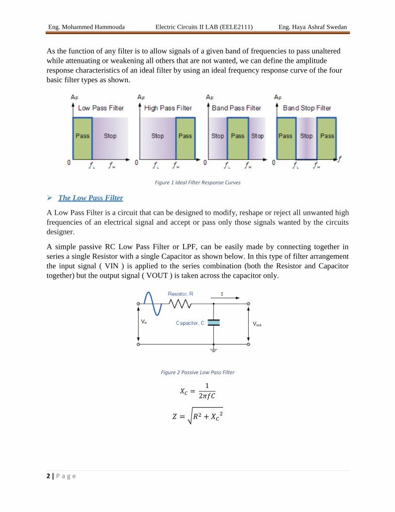
A simple passive RC Low Pass Filter or LPF, can be easily made by connecting together in
series a single Resistor with a single Capacitor as shown below. In this type of filter arrangement
the input signal ( VIN ) is applied to the series combination (both the Resistor and Capacitor
together) but the output signal ( VOUT ) is taken across the capacitor only.
Figure 2 Passive Low Pass Filter
√
Eng. Mohammed Hammouda Electric Circuits II LAB (EELE2111) Eng. Haya Ashraf Swedan
3 | P a g e
√ =
=
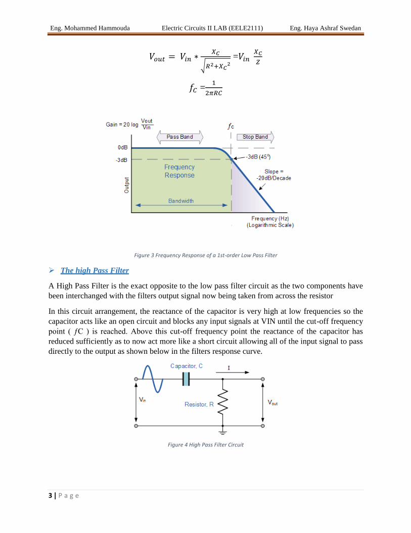
Figure 3 Frequency Response of a 1st-order Low Pass Filter
The high Pass Filter
A High Pass Filter is the exact opposite to the low pass filter circuit as the two components have
been interchanged with the filters output signal now being taken from across the resistor
In this circuit arrangement, the reactance of the capacitor is very high at low frequencies so the
capacitor acts like an open circuit and blocks any input signals at VIN until the cut-off frequency
point ( ƒC ) is reached. Above this cut-off frequency point the reactance of the capacitor has
reduced sufficiently as to now act more like a short circuit allowing all of the input signal to pass
directly to the output as shown below in the filters response curve.
Figure 4 High Pass Filter Circuit

Eng. Mohammed Hammouda Electric Circuits II LAB (EELE2111) Eng. Haya Ashraf Swedan
4 | P a g e
√
At Low :
At High :
Figure 5 Frequency Response of a 1st Order High Pass Filter
Passive Band Pass Filter
Band Pass Filters can be used to isolate or filter out certain frequencies that lie within a particular
band or range of frequencies. The cut-off frequency or ƒc point in a simple RC passive filter can
be accurately controlled using just a single resistor in series with a non-polarized capacitor, and
depending upon which way around they are connected, we have seen that either a Low Pass or a
High Pass filter is obtained.
One simple use for these types of passive filters is in audio amplifier applications or circuits such
as in loudspeaker crossover filters or pre-amplifier tone controls. Sometimes it is necessary to
only pass a certain range of frequencies that do not begin at 0Hz, (DC) or end at some upper high
frequency point but are within a certain range or band of frequencies, either narrow or wide.
Figure 6 Passive Band Pass Filter

Eng. Mohammed Hammouda Electric Circuits II LAB (EELE2111) Eng. Haya Ashraf Swedan
5 | P a g e
( ) ( )
( ) =
*( ) (
)
+
=
*(
) (
) +
,
Hence if the frequency is zero (i.e. D.C.) the impedance of the inductor is zero (i.e. a short
circuit) and the impedance of the capacitor is infinite (i.e. an open circuit), this is shown in the
circuit below.
Figure 7 When inductor is short and capacitor is open
Now if the frequency is infinite, the impedance of the inductor is infinite (i.e. an open circuit)
and the impedance of the capacitor is zero (i.e. a short circuit), this is shown in the circuit below:
Figure 8 When capacitor is short and inductor is open

Eng. Mohammed Hammouda Electric Circuits II LAB (EELE2111) Eng. Haya Ashraf Swedan
6 | P a g e
Center Frequency ( )
This is the frequency at which the transfer function is at a maximum:
=√
Cut off frequency ( , )
This is the frequency at which the transfer function equals (0.707) of the maximum value:
= -
+ √(
)
(
)
=
+ √(
)
(
)
Bandwidth (β)
This variable is the width of the pass band. (see graph below):
-
= [
√(
)
(
)] - [
√(
)
(
)] =
Quality factor ( )
This parameter is the ratio of the center frequency to the bandwidth. This gives a measure of the
pass band and can be used to describe the shape of the transfer function graph.
= √
= √
Eng. Mohammed Hammouda Electric Circuits II LAB (EELE2111) Eng. Haya Ashraf Swedan
7 | P a g e
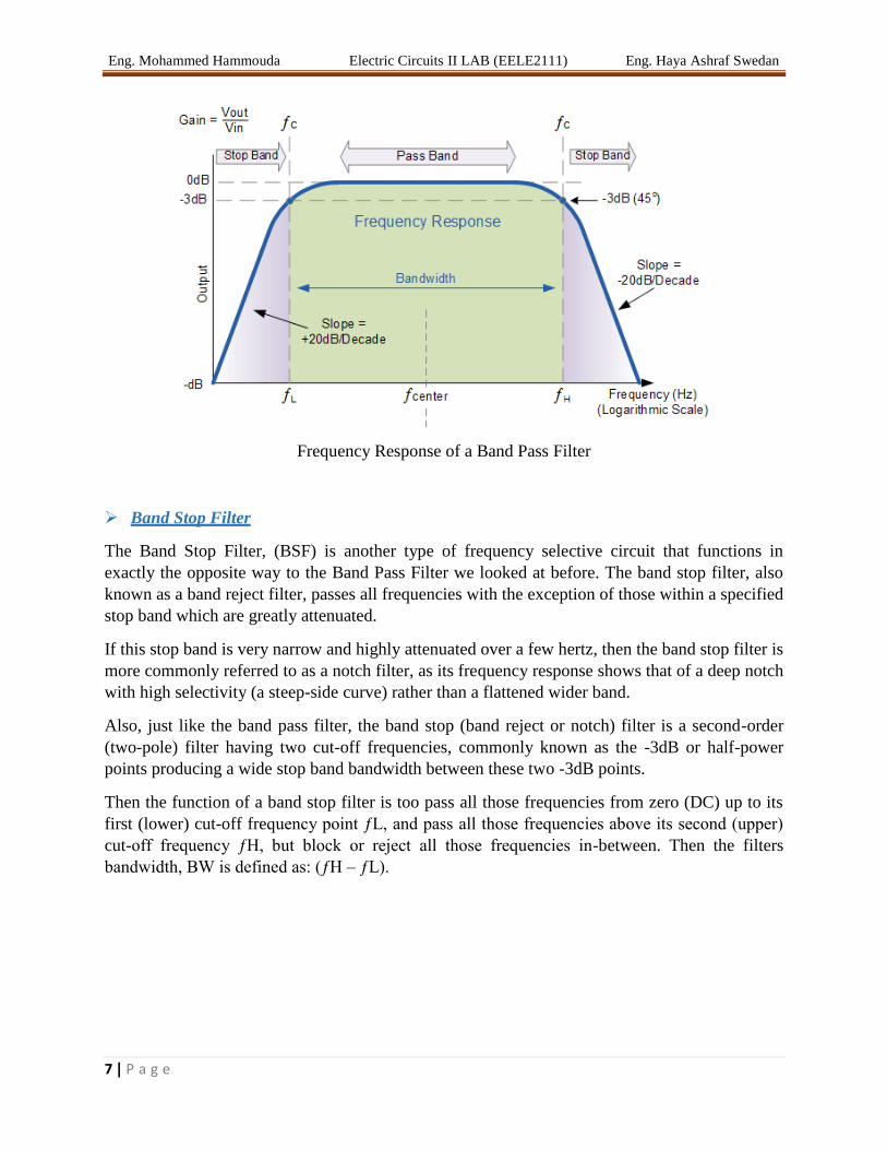
Frequency Response of a Band Pass Filter
Band Stop Filter
The Band Stop Filter, (BSF) is another type of frequency selective circuit that functions in
exactly the opposite way to the Band Pass Filter we looked at before. The band stop filter, also
known as a band reject filter, passes all frequencies with the exception of those within a specified
stop band which are greatly attenuated.
If this stop band is very narrow and highly attenuated over a few hertz, then the band stop filter is
more commonly referred to as a notch filter, as its frequency response shows that of a deep notch
with high selectivity (a steep-side curve) rather than a flattened wider band.
Also, just like the band pass filter, the band stop (band reject or notch) filter is a second-order
(two-pole) filter having two cut-off frequencies, commonly known as the -3dB or half-power
points producing a wide stop band bandwidth between these two -3dB points.
Then the function of a band stop filter is too pass all those frequencies from zero (DC) up to its
first (lower) cut-off frequency point ƒL, and pass all those frequencies above its second (upper)
cut-off frequency ƒH, but block or reject all those frequencies in-between. Then the filters
bandwidth, BW is defined as: (ƒH – ƒL).
Eng. Mohammed Hammouda Electric Circuits II LAB (EELE2111) Eng. Haya Ashraf Swedan
8 | P a g e
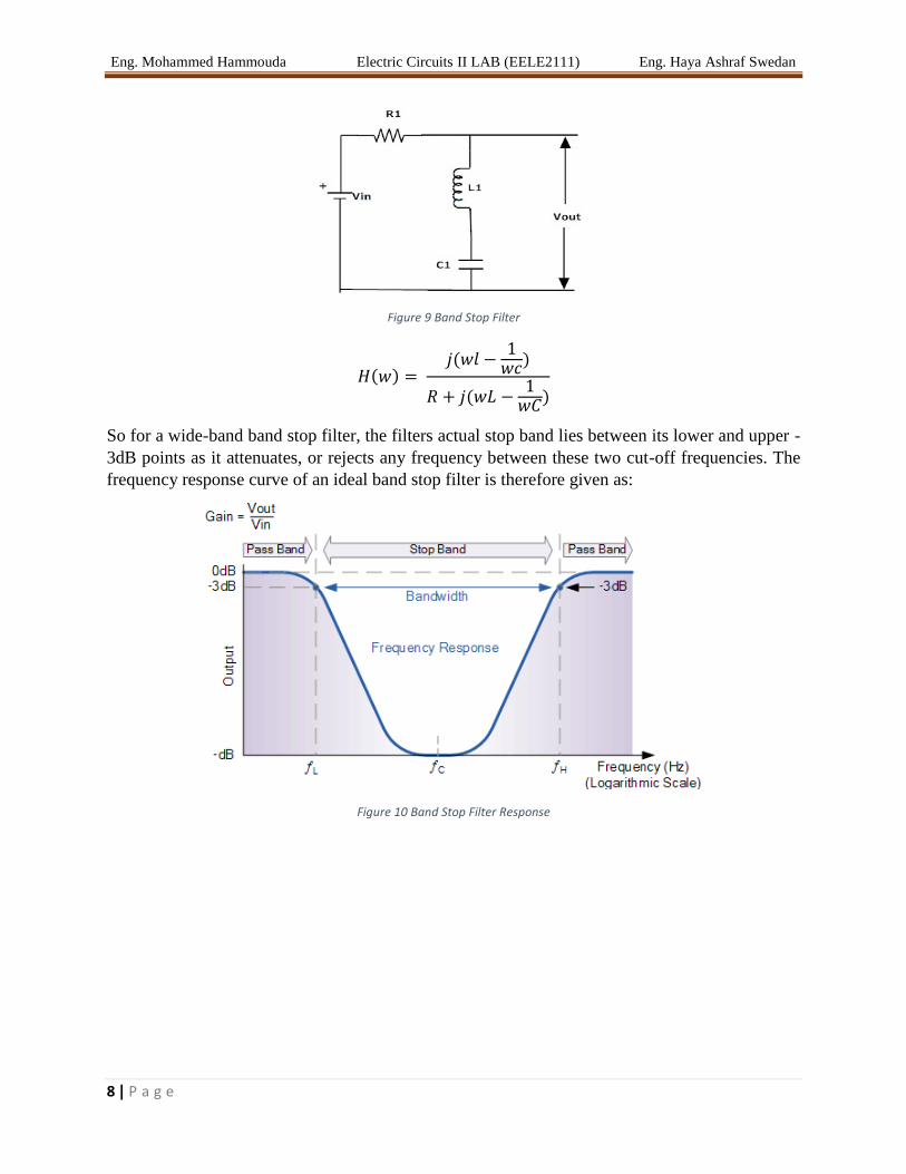
Figure 9 Band Stop Filter
( ) (
)
( )
So for a wide-band band stop filter, the filters actual stop band lies between its lower and upper -
3dB points as it attenuates, or rejects any frequency between these two cut-off frequencies. The
frequency response curve of an ideal band stop filter is therefore given as:
Figure 10 Band Stop Filter Response
Eng. Mohammed Hammouda Electric Circuits II LAB (EELE2111) Eng. Haya Ashraf Swedan
9 | P a g e
Practical Part: To Draw frequency response for each type of filter
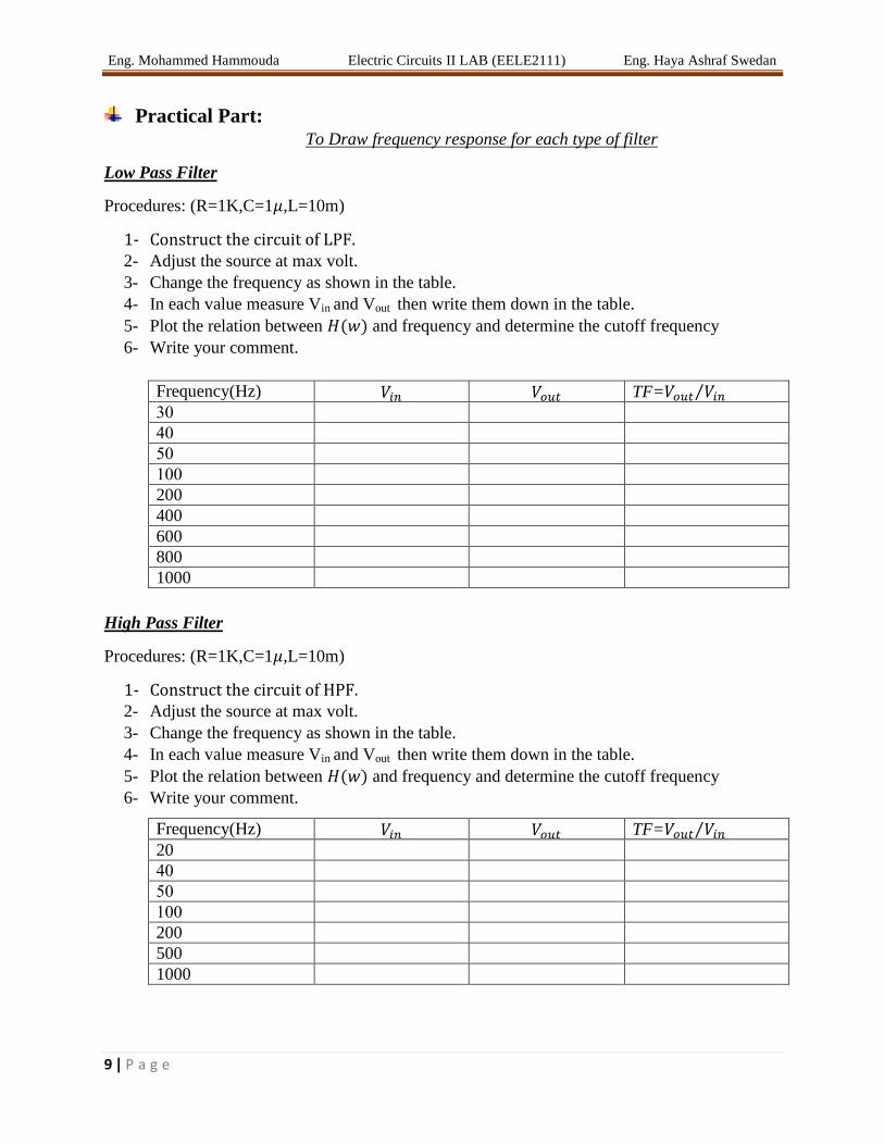
Low Pass Filter
Procedures: (R=1K,C=1 ,L=10m)
1- 2- Adjust the source at max volt.
3- Change the frequency as shown in the table.
4- In each value measure Vin and Vout then write them down in the table.
5- Plot the relation between ( ) and frequency and determine the cutoff frequency
6- Write your comment.
Frequency(Hz) TF= ⁄ 03
03
03
033
200
400
600
800
1000
High Pass Filter
Procedures: (R=1K,C=1 ,L=10m)
1- 2- Adjust the source at max volt.
3- Change the frequency as shown in the table.
4- In each value measure Vin and Vout then write them down in the table.
5- Plot the relation between ( ) and frequency and determine the cutoff frequency
6- Write your comment.
Frequency(Hz) TF= ⁄ 20
03
03
033
200
500
1000
Eng. Mohammed Hammouda Electric Circuits II LAB (EELE2111) Eng. Haya Ashraf Swedan
10 | P a g e
Band Pass Filter
Procedures: (R=1K,C=1 ,L=10m)
1- 2- Adjust the source at max volt.
3- Change the frequency as shown in the table.
4- In each value measure Vin and Vout then write them down in the table.
5- Plot the relation between ( ) and frequency and determine the cutoff frequency
6- Write your comment.
Frequency(Hz) TF= ⁄ 0
500
1000
0500
2500
3000
40k
Band Reject Filter
Procedures: (R=1K,C=1 ,L=10m)
1- 2- Adjust the source at max volt.
3- Change the frequency as shown in the table.
4- In each value measure Vin and Vout then write them down in the table.
5- Plot the relation between ( ) and frequency and determine the cutoff frequency
6- Write your comment.
Frequency(Hz) TF= ⁄ 0
500
1000
0500
2000
2500
3000
40k
![Fast Local Laplacian Filters: Theory and Applications · Fast Local Laplacian Filters: Theory and Applications • 3 Local Laplacian filtering. Paris et al. [2011] introduced local](https://img.pdfslide.us/doc/110x75/5c8ca33b09d3f236358c3284/fast-local-laplacian-filters-theory-and-applications-fast-local-laplacian-filters.jpg)