Embed Size (px)
Citation preview
Reulke 41
Film-based and Digital Sensors – Augmentation or Change in Paradigm?
RALF REULKE, Institute for Photogrammetry (ifp), Stuttgart
ABSTRACT Recent technology developments provide new solutions for high-resolution image acquisition for photogrammetric applications. These cameras are based on large CCD-matrices as well as CCD-line sensors and fulfill both: large field of view and high spatial resolution. Single- or multi-line cameras have been designed for spaceborne, airborne and terrestrial scanners to provide high-resolution wide angle or even panoramic imagery. Such cameras allow new approaches of 3D scene visualization and reconstruction as well as new applications in airborne and close range photogrammetry. This has impacts on camera design and development, calibration, image acquisition and data processing, but also on business and market.
1. INTRODUCTION
Recent technology developments have influenced photogrammetric technology, workflow and the self-understanding of the photogrammetric community. This has often been explained in various papers in the last few years (see e.g. Ackermann; 1995, Kraus; 2001, Heipke; 2003). Most of these papers refer to a special development in photogrammetry and speak about a science revolution or paradigm shift in the sense of Thomas S. Kuhn (Kuhn; 1996). New trends and developments are:
- Digital imaging, which is able to replace classical photo images for photogrammetric purposes
- Active systems (laser scanner and SAR) which are able to collect wide area digital surface models (DSM) especially in regions where data evaluation with classical cameras is complicated (city, forests)
- Direct geo-referencing with accurate camera location and line-of-sight (LOS) determination - Digital signal processing combined with available algorithms and computer power for fast
and unsupervised data processing Each of these developments simplifies the classical photogrammetric workflow, makes results more accurate and reliable, but opens photogrammetry also for new opportunities and has a lot of challenges. This paper analyses some of these technological developments and will focus on digital camera technologies as an initial point for this development and investigates the implications for photogrammetry. Modern camera systems, combined with geographic information system technologies, provide information about current and future resource potentials. The most extensive user of high-resolution camera technologies is aerial and close range photogrammetry General products are, for example, orthophotos and DSM, derived from stereo images. For photogrammetric application, film-based cameras with traditional techniques have normally been used up to now. The digital workflow starts after film development with film scanning and image processing including stereo visualization. By using different films these cameras also can be used for remote sensing tasks to some extent (e.g. land use or land cover classification).
Photogrammetric Week '03 Dieter Fritsch (Ed.) Wichmann Verlag, Heidelberg, 2003
42 Reulke
Extensive research and industrial developments within the last 10 years in CCD technology and position determination with GPS / INS as well as increasing computer performance and data storage capacity offer the opportunity to replace the film-based aerial camera for many applications and also to improve the quality of the photogrammetric and remote sensing products The paper introduces image geometries and possible detector arrays for high-resolution sensors. In the following chapters new developments for terrestrial, airborne and space borne sensors will be explained.
2. IMAGING PRINCIPLES FOR TERRESTRIAL, AIRBORNE AND SPACEBORNE DIGITAL SENSORS
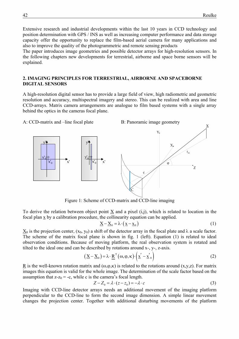
A high-resolution digital sensor has to provide a large field of view, high radiometric and geometric resolution and accuracy, multispectral imagery and stereo. This can be realized with area and line CCD-arrays. Matrix camera arrangements are analogue to film based systems with a single array behind the optics in the cameras focal plane. A: CCD-matrix and –line focal plate B: Panoramic image geometry
x'
y'
y'0x'0x'
y'
y'0x'0
Figure 1: Scheme of CCD-matrix and CCD-line imaging
To derive the relation between object point X and a pixel (i,j), which is related to location in the focal plan x by a calibration procedure, the collinearity equation can be applied. ( )0 0X X x x− = λ ⋅ − (1) X0 is the projection center, (x0, y0) a shift of the detector array in the focal plate and λ a scale factor. The scheme of the matrix focal plane is shown in fig. 1 (left). Equation (1) is related to ideal observation conditions. Because of moving platform, the real observation system is rotated and tilted to the ideal one and can be described by rotations around x-, y-, z-axis.
( ) ( ) ( )T0 0X X R , , x x′ ′− = λ ⋅ ω ϕ κ ⋅ − (2)
R is the well-known rotation matrix and (ω,ϕ,κ) is related to the rotations around (x,y,z). For matrix images this equation is valid for the whole image. The determination of the scale factor based on the assumption that z-z0 = -c, while c is the camera’s focal length. 0 0( )− = ⋅ − = − ⋅Z Z z z cλ λ (3) Imaging with CCD-line detector arrays needs an additional movement of the imaging platform perpendicular to the CCD-line to form the second image dimension. A simple linear movement changes the projection center. Together with additional disturbing movements of the platform
Reulke 43
(which can be expressed in e.g. roll, pitch and yaw for an airplane) the image formation is time dependent or related to the measured column j, while the row direction i is defined by the rigid CCD-line geometry.
( ) ( ) ( ) [ ]Tj T j j j0 0 0 0 0X X R , , x x with x x x , y y , c′ ′ ′ ′ ′ ′ ′− = λ ⋅ ω ϕ κ ⋅ − − = − − − (4)
In this model the scale factor is equivalent to equation (3). Panoramic imaging occurs with the rotation of the CCD-line camera perpendicular to the CCD-line and around the Y-axis. The column j is related to the rotation angle ϕj around y-axis. The unknown scale factor can be calculated from the square of the x-z components of this equation:
( ) ( )2 2XZXZ 0 0
r r X X Z Zc
λ = = − + − (5)
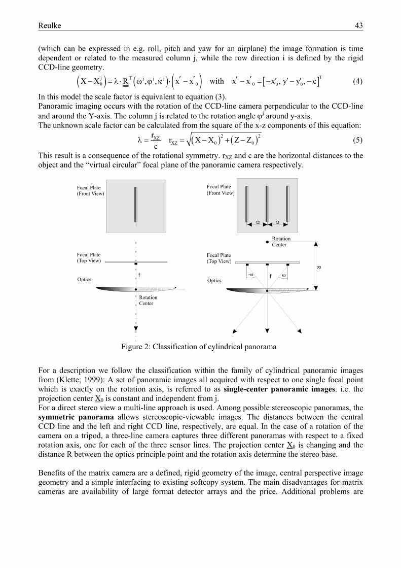
This result is a consequence of the rotational symmetry. rXZ and c are the horizontal distances to the object and the “virtual circular” focal plane of the panoramic camera respectively.
For a description we follow the classification within the family of cylindrical panoramic images from (Klette; 1999): A set of panoramic images all acquired with respect to one single focal point which is exactly on the rotation axis, is referred to as single-center panoramic images. i.e. the projection center X0 is constant and independent from j. For a direct stereo view a multi-line approach is used. Among possible stereoscopic panoramas, the symmetric panorama allows stereoscopic-viewable images. The distances between the central CCD line and the left and right CCD line, respectively, are equal. In the case of a rotation of the camera on a tripod, a three-line camera captures three different panoramas with respect to a fixed rotation axis, one for each of the three sensor lines. The projection center X0 is changing and the distance R between the optics principle point and the rotation axis determine the stereo base. Benefits of the matrix camera are a defined, rigid geometry of the image, central perspective image geometry and a simple interfacing to existing softcopy system. The main disadvantages for matrix cameras are availability of large format detector arrays and the price. Additional problems are
Focal Plate(Top View)
Optics
Focal Plate(Front View)
Rotation Center
f
Focal Plate(Top View)
Optics
Focal Plate(Front View)
Rotation Center
R
-ω ωf
a a
Figure 2: Classification of cylindrical panorama
44 Reulke
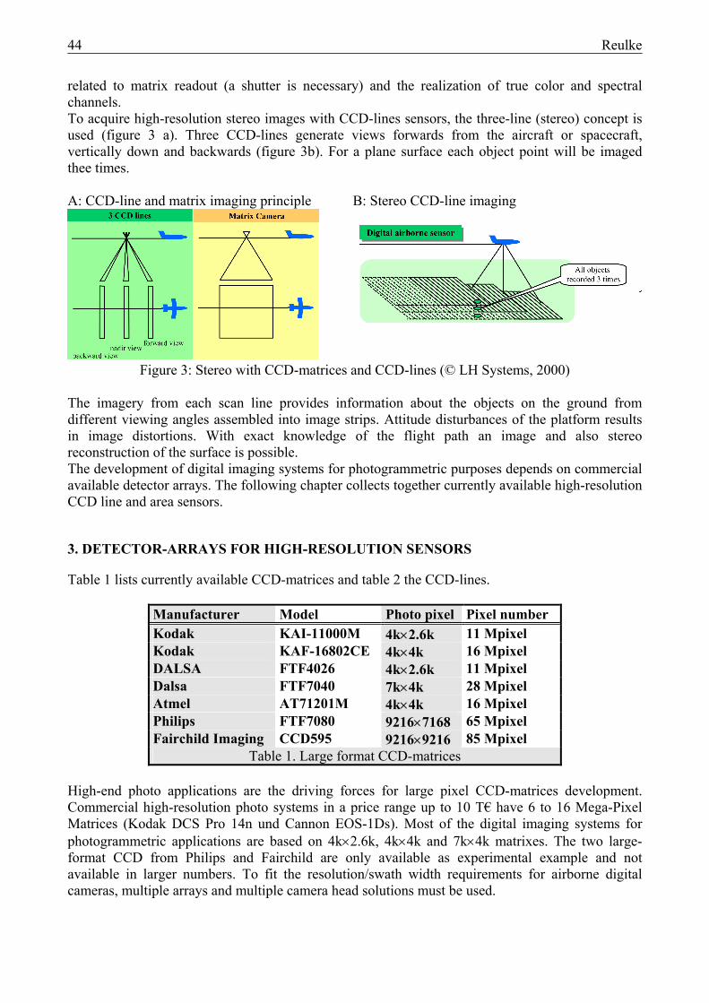
related to matrix readout (a shutter is necessary) and the realization of true color and spectral channels. To acquire high-resolution stereo images with CCD-lines sensors, the three-line (stereo) concept is used (figure 3 a). Three CCD-lines generate views forwards from the aircraft or spacecraft, vertically down and backwards (figure 3b). For a plane surface each object point will be imaged thee times. A: CCD-line and matrix imaging principle B: Stereo CCD-line imaging
Figure 3: Stereo with CCD-matrices and CCD-lines (© LH Systems, 2000)
The imagery from each scan line provides information about the objects on the ground from different viewing angles assembled into image strips. Attitude disturbances of the platform results in image distortions. With exact knowledge of the flight path an image and also stereo reconstruction of the surface is possible. The development of digital imaging systems for photogrammetric purposes depends on commercial available detector arrays. The following chapter collects together currently available high-resolution CCD line and area sensors.
3. DETECTOR-ARRAYS FOR HIGH-RESOLUTION SENSORS
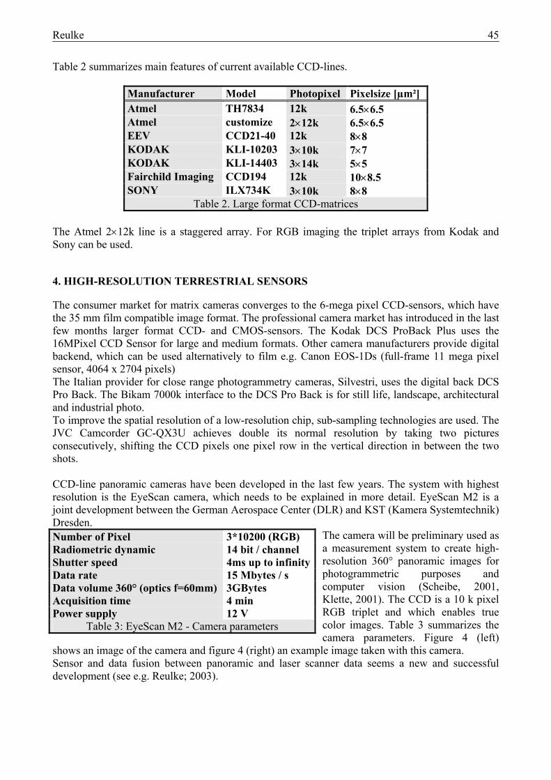
Table 1 lists currently available CCD-matrices and table 2 the CCD-lines.
Manufacturer Model Photo pixel Pixel number Kodak KAI-11000M 4k×2.6k 11 Mpixel Kodak KAF-16802CE 4k×4k 16 Mpixel DALSA FTF4026 4k×2.6k 11 Mpixel Dalsa FTF7040 7k×4k 28 Mpixel Atmel AT71201M 4k×4k 16 Mpixel Philips FTF7080 9216×7168 65 Mpixel Fairchild Imaging CCD595 9216×9216 85 Mpixel
Table 1. Large format CCD-matrices High-end photo applications are the driving forces for large pixel CCD-matrices development. Commercial high-resolution photo systems in a price range up to 10 T€ have 6 to 16 Mega-Pixel Matrices (Kodak DCS Pro 14n und Cannon EOS-1Ds). Most of the digital imaging systems for photogrammetric applications are based on 4k×2.6k, 4k×4k and 7k×4k matrixes. The two large-format CCD from Philips and Fairchild are only available as experimental example and not available in larger numbers. To fit the resolution/swath width requirements for airborne digital cameras, multiple arrays and multiple camera head solutions must be used.
Reulke 45
Table 2 summarizes main features of current available CCD-lines.
Manufacturer Model Photopixel Pixelsize [µm²] Atmel TH7834 12k 6.5×6.5 Atmel customize 2×12k 6.5×6.5 EEV CCD21-40 12k 8×8 KODAK KLI-10203 3×10k 7×7 KODAK KLI-14403 3×14k 5×5 Fairchild Imaging CCD194 12k 10×8.5 SONY ILX734K 3×10k 8×8
Table 2. Large format CCD-matrices The Atmel 2×12k line is a staggered array. For RGB imaging the triplet arrays from Kodak and Sony can be used.
4. HIGH-RESOLUTION TERRESTRIAL SENSORS
The consumer market for matrix cameras converges to the 6-mega pixel CCD-sensors, which have the 35 mm film compatible image format. The professional camera market has introduced in the last few months larger format CCD- and CMOS-sensors. The Kodak DCS ProBack Plus uses the 16MPixel CCD Sensor for large and medium formats. Other camera manufacturers provide digital backend, which can be used alternatively to film e.g. Canon EOS-1Ds (full-frame 11 mega pixel sensor, 4064 x 2704 pixels) The Italian provider for close range photogrammetry cameras, Silvestri, uses the digital back DCS Pro Back. The Bikam 7000k interface to the DCS Pro Back is for still life, landscape, architectural and industrial photo. To improve the spatial resolution of a low-resolution chip, sub-sampling technologies are used. The JVC Camcorder GC-QX3U achieves double its normal resolution by taking two pictures consecutively, shifting the CCD pixels one pixel row in the vertical direction in between the two shots. CCD-line panoramic cameras have been developed in the last few years. The system with highest resolution is the EyeScan camera, which needs to be explained in more detail. EyeScan M2 is a joint development between the German Aerospace Center (DLR) and KST (Kamera Systemtechnik) Dresden.
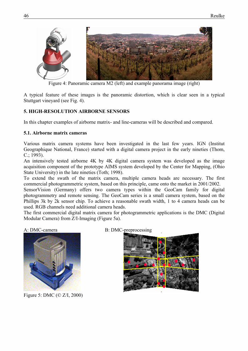
The camera will be preliminary used as a measurement system to create high-resolution 360° panoramic images for photogrammetric purposes and computer vision (Scheibe, 2001, Klette, 2001). The CCD is a 10 k pixel RGB triplet and which enables true color images. Table 3 summarizes the camera parameters. Figure 4 (left)
shows an image of the camera and figure 4 (right) an example image taken with this camera. Sensor and data fusion between panoramic and laser scanner data seems a new and successful development (see e.g. Reulke; 2003).
Number of Pixel 3*10200 (RGB) Radiometric dynamic 14 bit / channel Shutter speed 4ms up to infinity Data rate 15 Mbytes / s Data volume 360° (optics f=60mm) 3GBytes Acquisition time 4 min Power supply 12 V
Table 3: EyeScan M2 - Camera parameters
46 Reulke
Figure 4: Panoramic camera M2 (left) and example panorama image (right)
A typical feature of these images is the panoramic distortion, which is clear seen in a typical Stuttgart vineyard (see Fig. 4).
5. HIGH-RESOLUTION AIRBORNE SENSORS
In this chapter examples of airborne matrix- and line-cameras will be described and compared.
5.1. Airborne matrix cameras
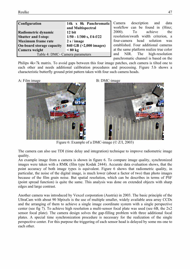
Various matrix camera systems have been investigated in the last few years. IGN (Institut Geographique National, France) started with a digital camera project in the early nineties (Thom, C.; 1993). An intensively tested airborne 4K by 4K digital camera system was developed as the image acquisition component of the prototype AIMS system developed by the Center for Mapping, (Ohio State University) in the late nineties (Toth; 1998). To extend the swath of the matrix camera, multiple camera heads are necessary. The first commercial photogrammetric system, based on this principle, came onto the market in 2001/2002. SensorVision (Germany) offers two camera types within the GeoCam family for digital photogrammetry and remote sensing. The GeoCam series is a small camera system, based on the Phillips 3k by 2k sensor chip. To achieve a reasonable swath width, 1 to 4 camera heads can be used. RGB channels need additional camera heads. The first commercial digital matrix camera for photogrammetric applications is the DMC (Digital Modular Camera) from Z/I-Imaging (Figure 5a). A: DMC-camera B: DMC-preprocessing
Figure 5: DMC (© Z/I, 2000)
Reulke 47
Camera description and data workflow can be found in (Hinz; 2000). To achieve the resolution/swath width criterion, a four-camera head solution was established. Four additional cameras at the same platform realize true color and NIR. The high-resolution panchromatic channel is based on the
Philips 4k×7k matrix. To avoid gaps between this four image patches, each camera is tilted one to each other and needs additional calibration procedures and processing. Figure 5.b shows a characteristic butterfly ground print pattern taken with four such camera heads. A: Film image B: DMC-image
Figure 6: Example of a DMC-image (© Z/I, 2003)
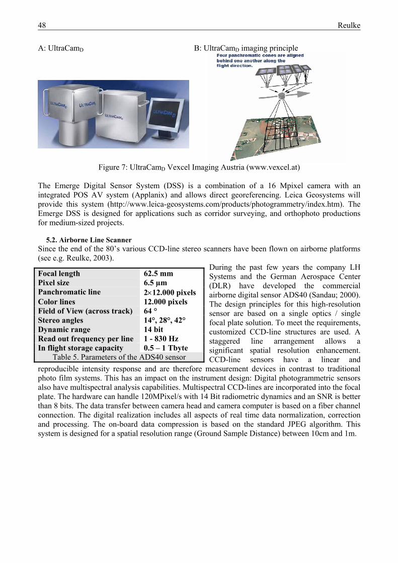
The camera can also use TDI (time delay and integration) technique to improve radiometric image quality. An example image from a camera is shown in figure 6. To compare image quality, synchronized images were taken with a RMK (film type Kodak 2444). Accurate data evaluation shows, that the point accuracy of both image types is equivalent. Figure 6 shows that radiometric quality, in particular, the noise of the digital image, is much lower (about a factor of two) than photo images because of the film grain noise. But spatial resolution, which can be describes in terms of PSF (point spread function) is quite the same. This analysis was done on extended objects with sharp edges and large contrast. Another camera was introduced by Vexcel corporation (Austria) in 2003. The basic principle of the UltraCam with about 90 Mpixels is the use of multiple smaller, widely available area array CCDs and the arranging of them to achieve a single image coordinate system with a single perspective center (see fig 7). To achieve high resolution a multi-sensor focal plate was used (see 6B, the 2x2 sensor focal plate). The camera design solves the gap-filling problem with three additional focal plates. A special time synchronization procedure is necessary for the realization of the single perspective center. For this purpose the triggering of each sensor head is delayed by some ms one to each other.
Configuration 14k x 8k Panchromatic and Multispectral
Radiometric dynamic 12 bit Shutter and f-stop: 1/50 - 1/300 s, f/4-f/22 Maximum frame rate 2 s / image On-board storage capacity 840 GB (>2,000 images) Camera weight < 80 kg
Table 4: DMC- Camera parameters
48 Reulke
A: UltraCamD B: UltraCamD imaging principle
Figure 7: UltraCamD Vexcel Imaging Austria (www.vexcel.at)
The Emerge Digital Sensor System (DSS) is a combination of a 16 Mpixel camera with an integrated POS AV system (Applanix) and allows direct georeferencing. Leica Geosystems will provide this system (http://www.leica-geosystems.com/products/photogrammetry/index.htm). The Emerge DSS is designed for applications such as corridor surveying, and orthophoto productions for medium-sized projects.
5.2. Airborne Line Scanner
Since the end of the 80’s various CCD-line stereo scanners have been flown on airborne platforms (see e.g. Reulke, 2003).
During the past few years the company LH Systems and the German Aerospace Center (DLR) have developed the commercial airborne digital sensor ADS40 (Sandau; 2000). The design principles for this high-resolution sensor are based on a single optics / single focal plate solution. To meet the requirements, customized CCD-line structures are used. A staggered line arrangement allows a significant spatial resolution enhancement. CCD-line sensors have a linear and
reproducible intensity response and are therefore measurement devices in contrast to traditional photo film systems. This has an impact on the instrument design: Digital photogrammetric sensors also have multispectral analysis capabilities. Multispectral CCD-lines are incorporated into the focal plate. The hardware can handle 120MPixel/s with 14 Bit radiometric dynamics and an SNR is better than 8 bits. The data transfer between camera head and camera computer is based on a fiber channel connection. The digital realization includes all aspects of real time data normalization, correction and processing. The on-board data compression is based on the standard JPEG algorithm. This system is designed for a spatial resolution range (Ground Sample Distance) between 10cm and 1m.
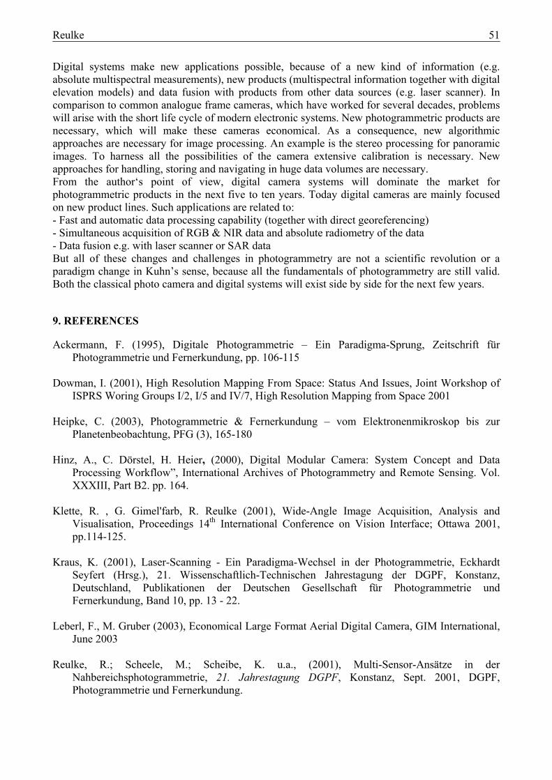
Focal length 62.5 mm Pixel size 6.5 µm Panchromatic line 2×12.000 pixels Color lines 12.000 pixels Field of View (across track) 64 ° Stereo angles 14°, 28°, 42° Dynamic range 14 bit Read out frequency per line 1 - 830 Hz In flight storage capacity 0.5 – 1 Tbyte
Table 5. Parameters of the ADS40 sensor
Reulke 49
A: ADS40 B: Example Image
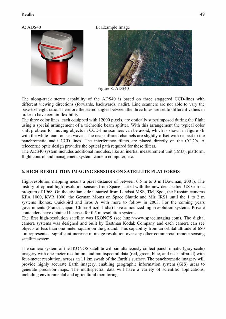
Figure 8: ADS40
The along-track stereo capability of the ADS40 is based on three staggered CCD-lines with different viewing directions (forwards, backwards, nadir). Line scanners are not able to vary the base-to-height ratio. Therefore the stereo angles between the three lines are set to different values in order to have certain flexibility. The three color lines, each equipped with 12000 pixels, are optically superimposed during the flight using a special arrangement of a trichroitic beam splitter. With this arrangement the typical color shift problem for moving objects in CCD-line scanners can be avoid, which is shown in figure 8B with the white foam on sea waves. The near infrared channels are slightly offset with respect to the panchromatic nadir CCD lines. The interference filters are placed directly on the CCD’s. A telecentric optic design provides the optical path required for these filters. The ADS40 system includes additional modules, like an inertial measurement unit (IMU), platform, flight control and management system, camera computer, etc.
6. HIGH-RESOLUTION IMAGING SENSORS ON SATELLITE PLATFORMS
High-resolution mapping means a pixel distance of between 0.5 m to 3 m (Dowman; 2001). The history of optical high-resolution sensors from Space started with the now declassified US Corona program of 1968. On the civilian side it started from Landsat MSS, TM, Spot, the Russian cameras KFA 1000, KVR 1000, the German Moms on Space Shuttle and Mir, IRS1 until the 1 to 2 m systems Ikonos, Quickbird and Eros A with more to follow in 2003. For the coming years governments (France, Japan, China-Brazil, India) have announced high-resolution systems. Private contenders have obtained licenses for 0.5 m resolution systems. The first high-resolution satellite was IKONOS (see http://www.spaceimaging.com). The digital camera systems was designed and built by Eastman Kodak Company and each camera can see objects of less than one-meter square on the ground. This capability from an orbital altitude of 680 km represents a significant increase in image resolution over any other commercial remote sensing satellite system. The camera system of the IKONOS satellite will simultaneously collect panchromatic (gray-scale) imagery with one-meter resolution, and multispectral data (red, green, blue, and near infrared) with four-meter resolution, across an 11 km swath of the Earth’s surface. The panchromatic imagery will provide highly accurate Earth imagery, enabling geographic information system (GIS) users to generate precision maps. The multispectral data will have a variety of scientific applications, including environmental and agricultural monitoring.

50 Reulke
Airborne and space borne sensors complement each other. The present handicaps are not in the obtainment of the imagery, but in it’s pricing, since aerial photographic coverage, if obtainable, is cheaper.
7. MULTISPECTRAL CHANNELS OF AIRBORNE AND SPACEBORNE SCANNERS
Multispectral channels, in addition to the stereo channels, are an inherent part of today imaging systems. Main differences to classical photo images digital imaging systems allows absolute radiance measurements and to acquire RGB and NIR images simultaneously. Multispectral imagery with high spatial resolution opens new remote sensing capabilities. Data fusion between the channels and other sensors together with additional digital elevation models derived from panchromatic stereo data create new scientific opportunities. Besides multispectral applications, true color images become more important for photogrammetric applications and are to be derived from color processed multispectral images. When choosing multispectral bands narrow band filters on interesting spectral features are necessary. Therefore true color images have to be derived from the multispectral channels. Figure 8 shows the spectral channels of selected airborne and space borne instruments.
Figure 9: Spectral channels of selected airborne and space-borne instruments
For comparison a vegetation reflection curve is visualize. TM (Thematic Mapper) is the prototype for all multispectral systems. The systems in the upper block (from TM to IKONOS) are space-borne systems. Except for IKONOS all systems are only multispectral systems. DPA, HRSC and ADS are airborne systems.
8. CONCLUSIONS
This paper explains new developments in high-resolution imaging. This technology opens new opportunities, different camera geometry (e.g. direct capture of panoramic images without stitching) and multispectral capabilities. Digital systems are cost saving (no film, no photo lab and better automation possibility), the product derivation is time saving (no film development, no scanning and possible automation of the digital workflow), and the images can have higher quality (higher radiometric dynamics and better signal to noise ratio, reproducible color and in-flight image control).
Reulke 51
Digital systems make new applications possible, because of a new kind of information (e.g. absolute multispectral measurements), new products (multispectral information together with digital elevation models) and data fusion with products from other data sources (e.g. laser scanner). In comparison to common analogue frame cameras, which have worked for several decades, problems will arise with the short life cycle of modern electronic systems. New photogrammetric products are necessary, which will make these cameras economical. As a consequence, new algorithmic approaches are necessary for image processing. An example is the stereo processing for panoramic images. To harness all the possibilities of the camera extensive calibration is necessary. New approaches for handling, storing and navigating in huge data volumes are necessary. From the author‘s point of view, digital camera systems will dominate the market for photogrammetric products in the next five to ten years. Today digital cameras are mainly focused on new product lines. Such applications are related to: - Fast and automatic data processing capability (together with direct georeferencing) - Simultaneous acquisition of RGB & NIR data and absolute radiometry of the data - Data fusion e.g. with laser scanner or SAR data But all of these changes and challenges in photogrammetry are not a scientific revolution or a paradigm change in Kuhn’s sense, because all the fundamentals of photogrammetry are still valid. Both the classical photo camera and digital systems will exist side by side for the next few years.
9. REFERENCES
Ackermann, F. (1995), Digitale Photogrammetrie – Ein Paradigma-Sprung, Zeitschrift für Photogrammetrie und Fernerkundung, pp. 106-115
Dowman, I. (2001), High Resolution Mapping From Space: Status And Issues, Joint Workshop of
ISPRS Woring Groups I/2, I/5 and IV/7, High Resolution Mapping from Space 2001 Heipke, C. (2003), Photogrammetrie & Fernerkundung – vom Elektronenmikroskop bis zur
Planetenbeobachtung, PFG (3), 165-180 Hinz, A., C. Dörstel, H. Heier, (2000), Digital Modular Camera: System Concept and Data
Processing Workflow”, International Archives of Photogrammetry and Remote Sensing. Vol. XXXIII, Part B2. pp. 164.
Klette, R. , G. Gimel'farb, R. Reulke (2001), Wide-Angle Image Acquisition, Analysis and
Visualisation, Proceedings 14th International Conference on Vision Interface; Ottawa 2001, pp.114-125.
Kraus, K. (2001), Laser-Scanning - Ein Paradigma-Wechsel in der Photogrammetrie, Eckhardt
Seyfert (Hrsg.), 21. Wissenschaftlich-Technischen Jahrestagung der DGPF, Konstanz, Deutschland, Publikationen der Deutschen Gesellschaft für Photogrammetrie und Fernerkundung, Band 10, pp. 13 - 22.
Leberl, F., M. Gruber (2003), Economical Large Format Aerial Digital Camera, GIM International,
June 2003 Reulke, R.; Scheele, M.; Scheibe, K. u.a., (2001), Multi-Sensor-Ansätze in der
Nahbereichsphotogrammetrie, 21. Jahrestagung DGPF, Konstanz, Sept. 2001, DGPF, Photogrammetrie und Fernerkundung.

52 Reulke
Reulke, R. (2003), Design and Application of High-Resolution Imaging Systems, GIS Geo-Informationssysteme, p. 30-37, 3/2003
Sandau, R., B. Braunecker, H. Driescher, A. Eckardt, S. Hilbert, J. Hutton, W. Kirchofer, E.
Lithopoulos, R. Reulke, S. Wicki (2000), Design Principles of the LH SYSTEMS ADS40 Airborne Digital Sensor, International Archives of Photogrammetry and Remote Sensing. Vol. XXXIII, Part B1. Amsterdam 2000, pp.258
Scheibe, K., Korsitzky, H., Reulke, R., Scheele, M., Solbrig, M. (2001), EYESCAN – A high
resolution digital panoramic camera, LNCS 1998, Springer, Berlin 2001, pp. 77. Thom, C., I. Juvillier (1993), Experiences with a digital camera at Institut Geographique National
(France). In: Photogrammetric Week ‘93, Eds. D. Fritsch/D. Hobbie, Wichmann, Karlsruhe, pp.73-83.
Thomas S. Kuhn (1996), The Structure of Scientific Revolutions, The University of Chicago Press,
Third edition Toth, C. (1998), Airborne Experiences with a 4K by 4K CCD Sensor, Proc. ASPRS-ACSM, pp.
163-168.