Embed Size (px)
Citation preview
D3DV2.00
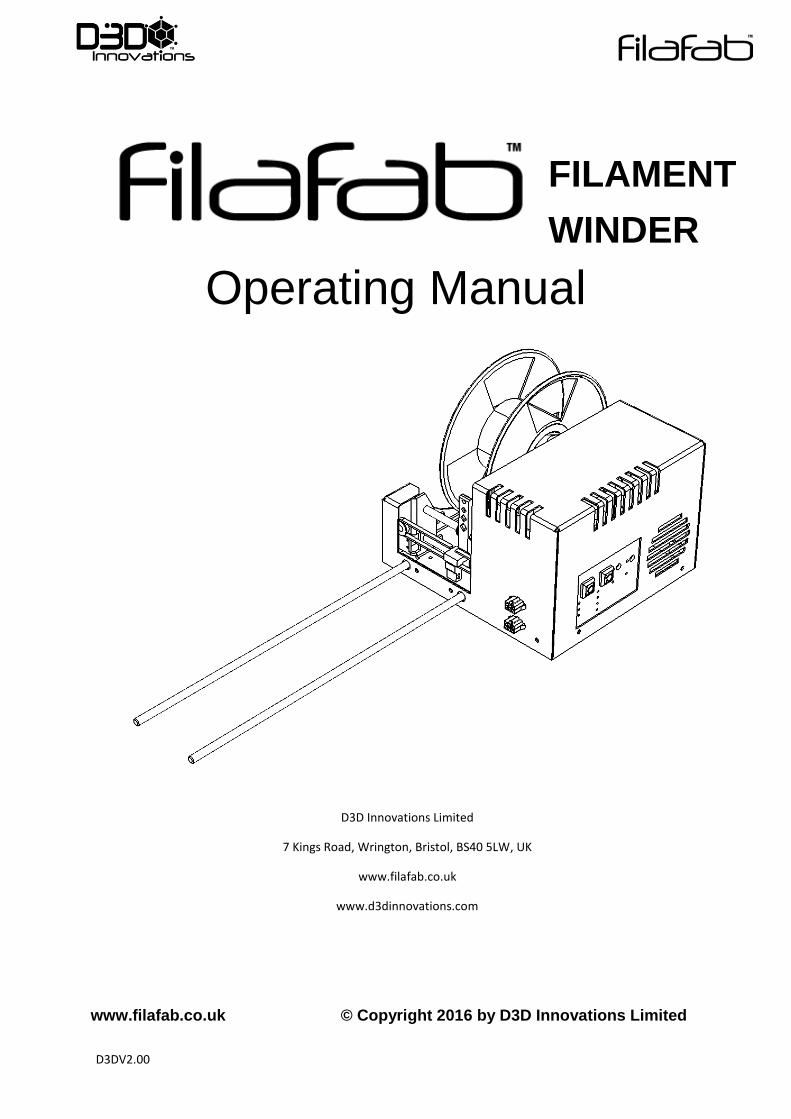
Operating Manual
D3D Innovations Limited
7 Kings Road, Wrington, Bristol, BS40 5LW, UK
www.filafab.co.uk
www.d3dinnovations.com
www.filafab.co.uk © Copyright 2016 by D3D Innovations Limited
FILAMENT
WINDER

D3DV2.00
CONTENTS
Overview ................................................................................................................................................................. 3
Before you begin................................................................................................................................................. 3
Control Panel ...................................................................................................................................................... 4
Front View .......................................................................................................................................................... 6
Rear View ............................................................................................................................................................ 7
Side View ............................................................................................................................................................ 8
Filament Sledge ...................................................................................................................................................... 9
Sledge Calibration ............................................................................................................................................. 10
Calibration Steps ............................................................................................................................................... 11
Open Peripheral System (OPS) ............................................................................................................................. 12
Firmware Update .......................................................................................................................................... 12
FilaFab Peripherals............................................................................................................................................ 13
OPS Connections ............................................................................................................................................... 17
Typical Winder Configurations ......................................................................................................................... 18
Example SETUP - CONNECTIONS ...................................................................................................................... 19
Example SETUP - AUTOSPOOLER ...................................................................................................................... 20
Connect Peripherals ............................................................................................................................................. 21
Fitting Spool .......................................................................................................................................................... 22
Starting up ............................................................................................................................................................ 23
Important Notes ............................................................................................................................................... 23
Select mode ...................................................................................................................................................... 24
Start/pause ........................................................................................................................................................... 26
Winding Filament.............................................................................................................................................. 26
Notes ................................................................................................................................................................ 27

D3DV2.00
OVERVIEW
Thank you for purchasing a FilaFab Filament Winder
BEFORE YOU BEGIN
The winding system has been optimised for use with FilaFab Desktop Extruders. The system
has been designed to be flexible and adaptable to your filament production requirements
rather than to be optimised for a single material/diameter only. The flexibility provided by
the system also means that it can take several attempts and some trial and error before the
optimal setup is achieved.
Please subscribe to our spam free mailing list at www.filafab.co.uk for news, instructional
videos, updates and more.
D3DV2.00
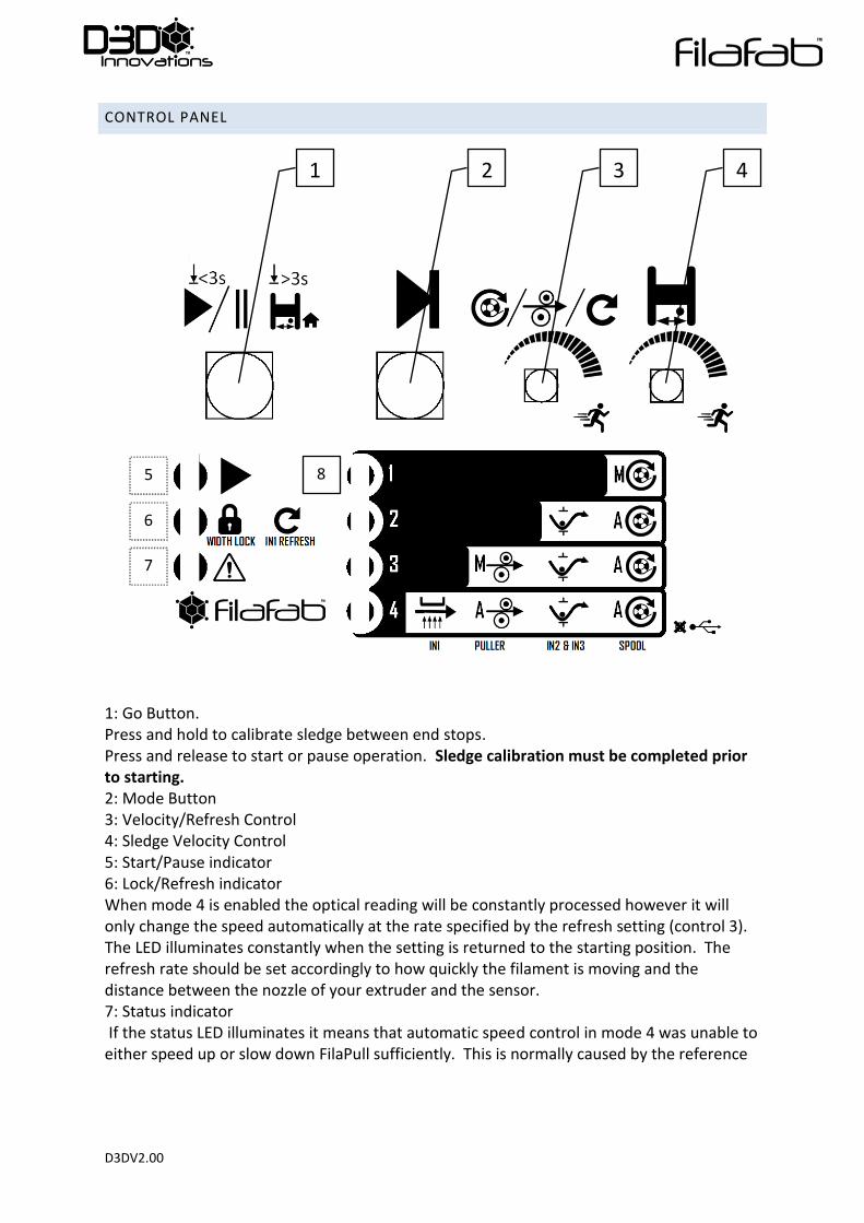
CONTROL PANEL
1: Go Button. Press and hold to calibrate sledge between end stops. Press and release to start or pause operation. Sledge calibration must be completed prior to starting. 2: Mode Button 3: Velocity/Refresh Control 4: Sledge Velocity Control 5: Start/Pause indicator 6: Lock/Refresh indicator When mode 4 is enabled the optical reading will be constantly processed however it will only change the speed automatically at the rate specified by the refresh setting (control 3). The LED illuminates constantly when the setting is returned to the starting position. The refresh rate should be set accordingly to how quickly the filament is moving and the distance between the nozzle of your extruder and the sensor. 7: Status indicator If the status LED illuminates it means that automatic speed control in mode 4 was unable to either speed up or slow down FilaPull sufficiently. This is normally caused by the reference
1 2 3 4
5
6
7
8

D3DV2.00
settings being too high or low since the motor has a maximum and minimum speed which cannot be overcome. Changing the reference speed setting or using a different nozzle will normally remove this issue. 8: Mode indicators Each mode is indicated by an LED. If all LEDs are off then USB mode (if supported) is established.
D3DV2.00
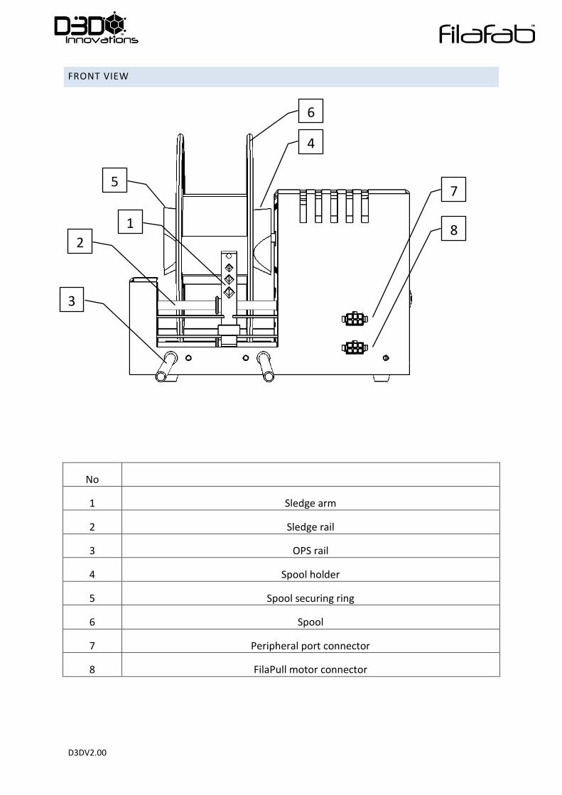
FRONT VIEW
No
1 Sledge arm
2 Sledge rail
3 OPS rail
4 Spool holder
5 Spool securing ring
6 Spool
7 Peripheral port connector
8 FilaPull motor connector
7
8
4
2
1
3
5
6
D3DV2.00
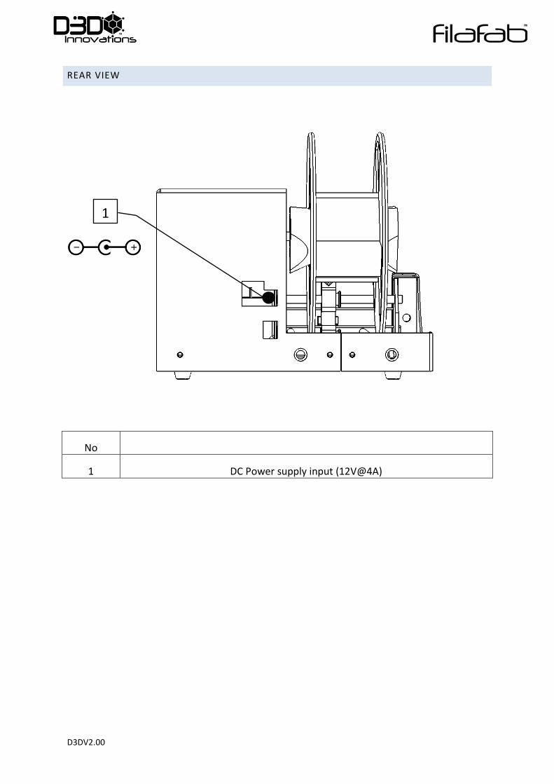
REAR VIEW
No
1 DC Power supply input (12V@4A)
1
D3DV2.00
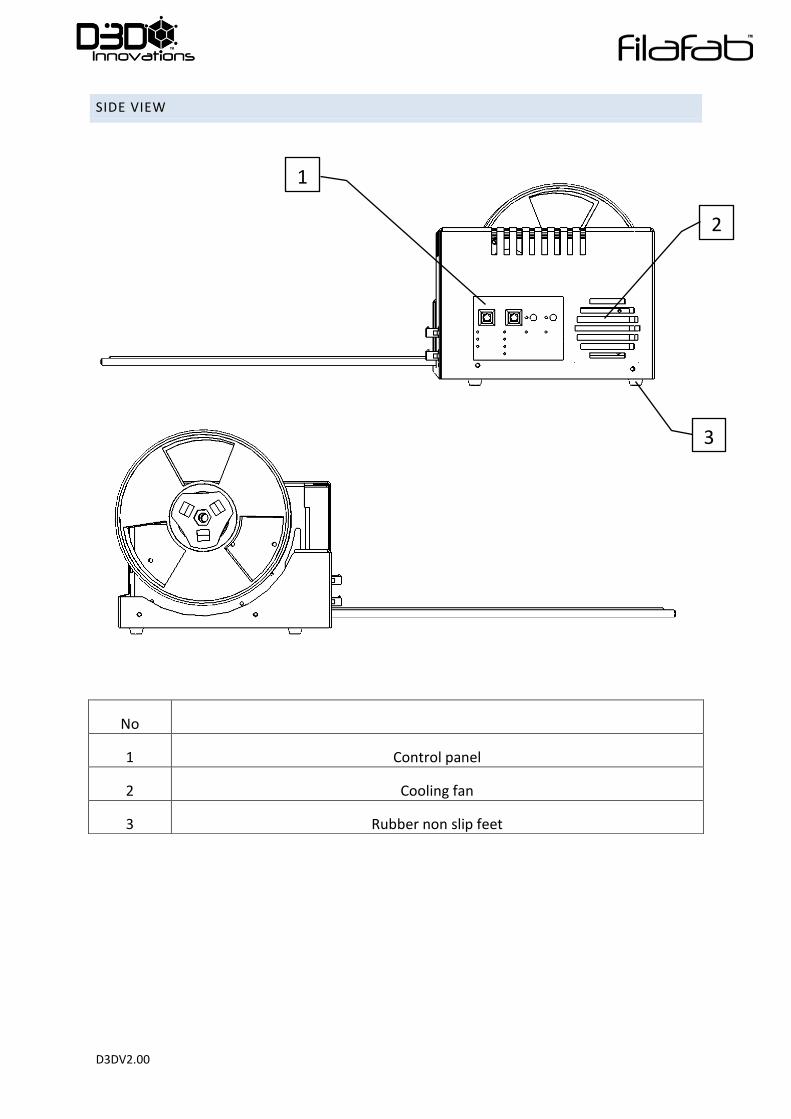
SIDE VIEW
No
1 Control panel
2 Cooling fan
3 Rubber non slip feet
1
2
3
D3DV2.00
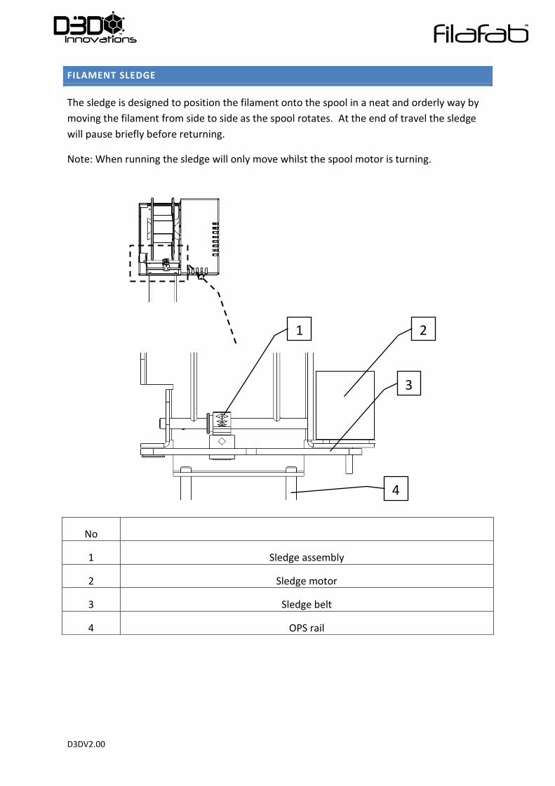
FILAMENT SLEDGE
The sledge is designed to position the filament onto the spool in a neat and orderly way by
moving the filament from side to side as the spool rotates. At the end of travel the sledge
will pause briefly before returning.
Note: When running the sledge will only move whilst the spool motor is turning.
No
1 Sledge assembly
2 Sledge motor
3 Sledge belt
4 OPS rail
2
3
1
4
D3DV2.00
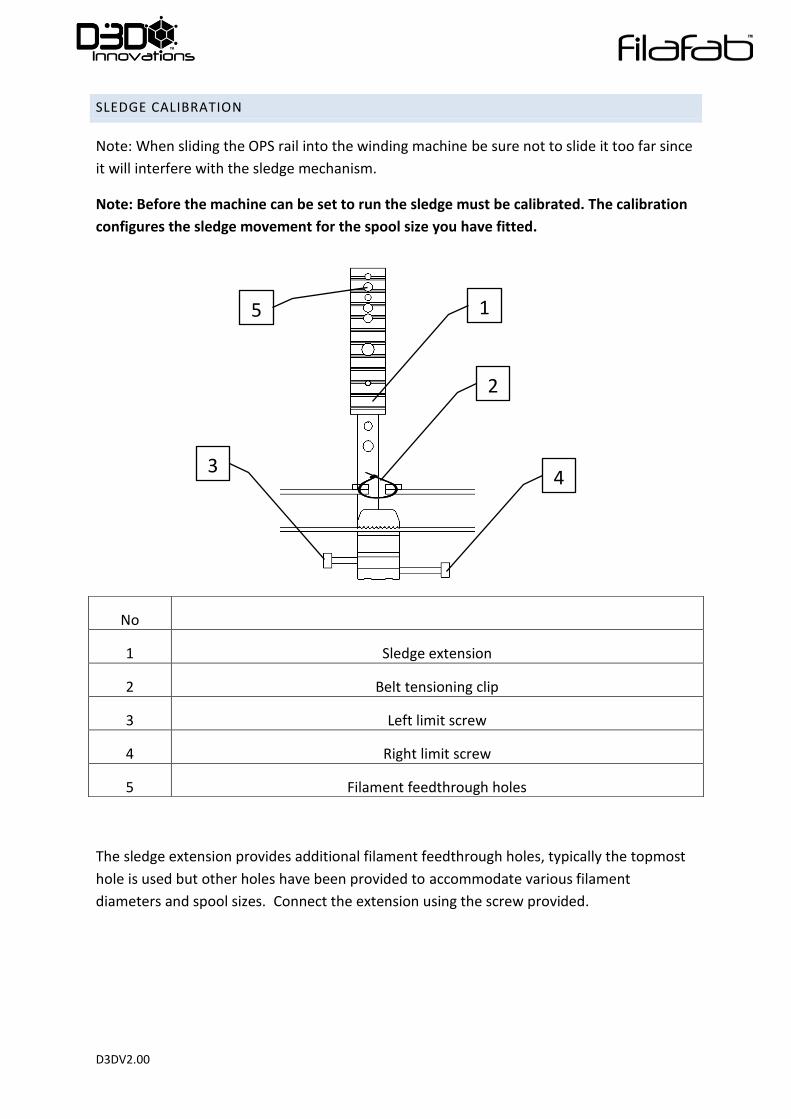
SLEDGE CALIBRATION
Note: When sliding the OPS rail into the winding machine be sure not to slide it too far since
it will interfere with the sledge mechanism.
Note: Before the machine can be set to run the sledge must be calibrated. The calibration
configures the sledge movement for the spool size you have fitted.
The sledge extension provides additional filament feedthrough holes, typically the topmost
hole is used but other holes have been provided to accommodate various filament
diameters and spool sizes. Connect the extension using the screw provided.
No
1 Sledge extension
2 Belt tensioning clip
3 Left limit screw
4 Right limit screw
5 Filament feedthrough holes
1
2
4 3
5

D3DV2.00
CALIBRATION STEPS
Hold the green control panel button for 3 seconds or more to initiate calibration, the sledge
will move towards end limit switch 1 and then towards end limit switch 2. The sledge will
automatically move off the switch once contact has been made. Now when the machine
runs the sledge will move between these pre-calibrated positions.
To adjust the position of the sledge relative to the end limit switches adjust the screws on
the sledge.
Note: If the belt becomes slack then it may be necessary to periodically tighten the belt
tension by tightening the belt tensioning clip using a pair of pliers.

D3DV2.00
OPEN PERIPHERAL SYSTEM (OPS)
The Open Peripheral System (OPS) has been designed to give you a method of connecting
your own peripherals/sensors and modules to the system to give you ultimate flexibility in
producing the filament you need.
At the time of writing this manual the embedded firmware (V1.0) supports a number of
actions as dictated by the mode button. As more peripherals become available it may be
necessary to update the embedded firmware to take advantage of the new peripherals.
We at FilaFab have designed a number of OPS modules for use with the winding system,
many modules include 3D printed parts which can be downloaded freely to
share/modify/upgrade or simply 3D print. Modules are also available to purchase pre-
assembled at www.filafab.co.uk.
You can also sign up for out newsletter at www.filafab.co.uk to keep up to date with latest
developments.
FIRMWARE UPDATE
From time to time we will release new features which will include performance upgrades,
bug fixes and new features. Contact the FilaFab team for more information.
D3DV2.00
FILAFAB PERIPHERALS
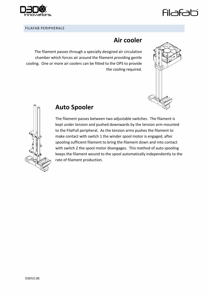
Air cooler
The filament passes through a specially designed air circulation
chamber which forces air around the filament providing gentle
cooling. One or more air coolers can be fitted to the OPS to provide
the cooling required.
Auto Spooler
The filament passes between two adjustable switches. The filament is
kept under tension and pushed downwards by the tension arm mounted
to the FilaPull peripheral. As the tension arms pushes the filament to
make contact with switch 1 the winder spool motor is engaged, after
spooling sufficient filament to bring the filament down and into contact
with switch 2 the spool motor disengages. This method of auto spooling
keeps the filament wound to the spool automatically independently to the
rate of filament production.
D3DV2.00
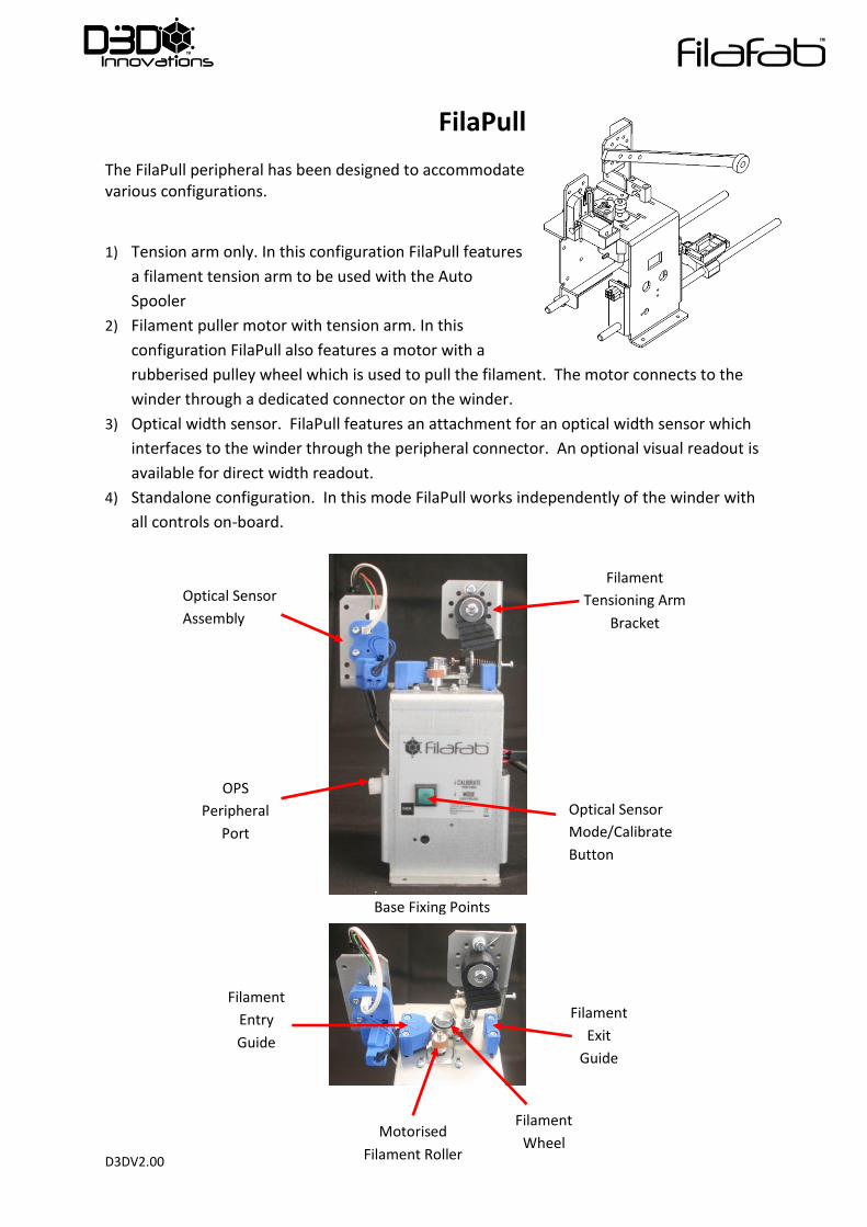
FilaPull
The FilaPull peripheral has been designed to accommodate various configurations.
1) Tension arm only. In this configuration FilaPull features
a filament tension arm to be used with the Auto
Spooler
2) Filament puller motor with tension arm. In this
configuration FilaPull also features a motor with a
rubberised pulley wheel which is used to pull the filament. The motor connects to the
winder through a dedicated connector on the winder.
3) Optical width sensor. FilaPull features an attachment for an optical width sensor which
interfaces to the winder through the peripheral connector. An optional visual readout is
available for direct width readout.
4) Standalone configuration. In this mode FilaPull works independently of the winder with
all controls on-board.
Optical Sensor
Assembly
Optical Sensor
Mode/Calibrate
Button
Base Fixing Points
OPS
Peripheral
Port
Filament
Tensioning Arm
Bracket
Filament
Entry
Guide
Filament
Exit
Guide
Motorised
Filament Roller
Filament
Wheel
D3DV2.00
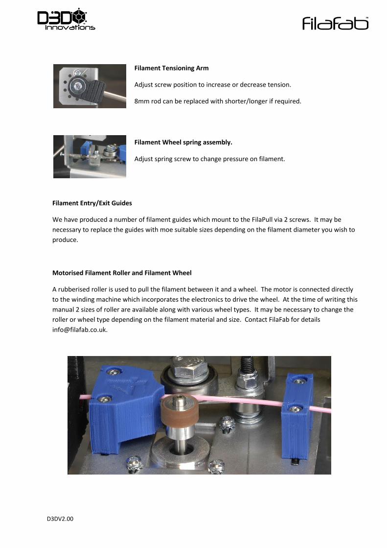
Filament Tensioning Arm
Adjust screw position to increase or decrease tension.
8mm rod can be replaced with shorter/longer if required.
Filament Wheel spring assembly.
Adjust spring screw to change pressure on filament.
Filament Entry/Exit Guides
We have produced a number of filament guides which mount to the FilaPull via 2 screws. It may be
necessary to replace the guides with moe suitable sizes depending on the filament diameter you wish to
produce.
Motorised Filament Roller and Filament Wheel
A rubberised roller is used to pull the filament between it and a wheel. The motor is connected directly
to the winding machine which incorporates the electronics to drive the wheel. At the time of writing this
manual 2 sizes of roller are available along with various wheel types. It may be necessary to change the
roller or wheel type depending on the filament material and size. Contact FilaFab for details
D3DV2.00
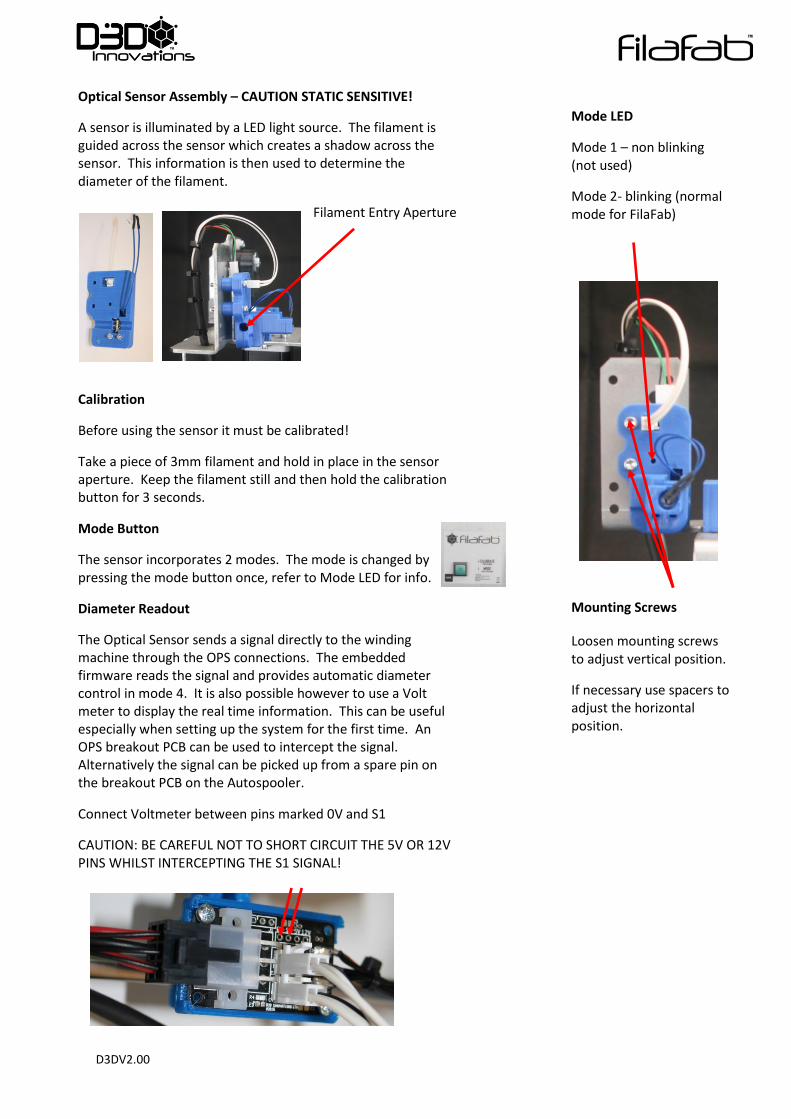
Optical Sensor Assembly – CAUTION STATIC SENSITIVE!
A sensor is illuminated by a LED light source. The filament is guided across the sensor which creates a shadow across the sensor. This information is then used to determine the diameter of the filament.
Filament Entry Aperture
Calibration
Before using the sensor it must be calibrated!
Take a piece of 3mm filament and hold in place in the sensor aperture. Keep the filament still and then hold the calibration button for 3 seconds.
Mode Button
The sensor incorporates 2 modes. The mode is changed by pressing the mode button once, refer to Mode LED for info.
Diameter Readout
The Optical Sensor sends a signal directly to the winding machine through the OPS connections. The embedded firmware reads the signal and provides automatic diameter control in mode 4. It is also possible however to use a Volt meter to display the real time information. This can be useful especially when setting up the system for the first time. An OPS breakout PCB can be used to intercept the signal. Alternatively the signal can be picked up from a spare pin on the breakout PCB on the Autospooler.
Connect Voltmeter between pins marked 0V and S1
CAUTION: BE CAREFUL NOT TO SHORT CIRCUIT THE 5V OR 12V PINS WHILST INTERCEPTING THE S1 SIGNAL!
Mounting Screws
Loosen mounting screws to adjust vertical position.
If necessary use spacers to adjust the horizontal position.
Mode LED
Mode 1 – non blinking (not used)
Mode 2- blinking (normal mode for FilaFab)
D3DV2.00
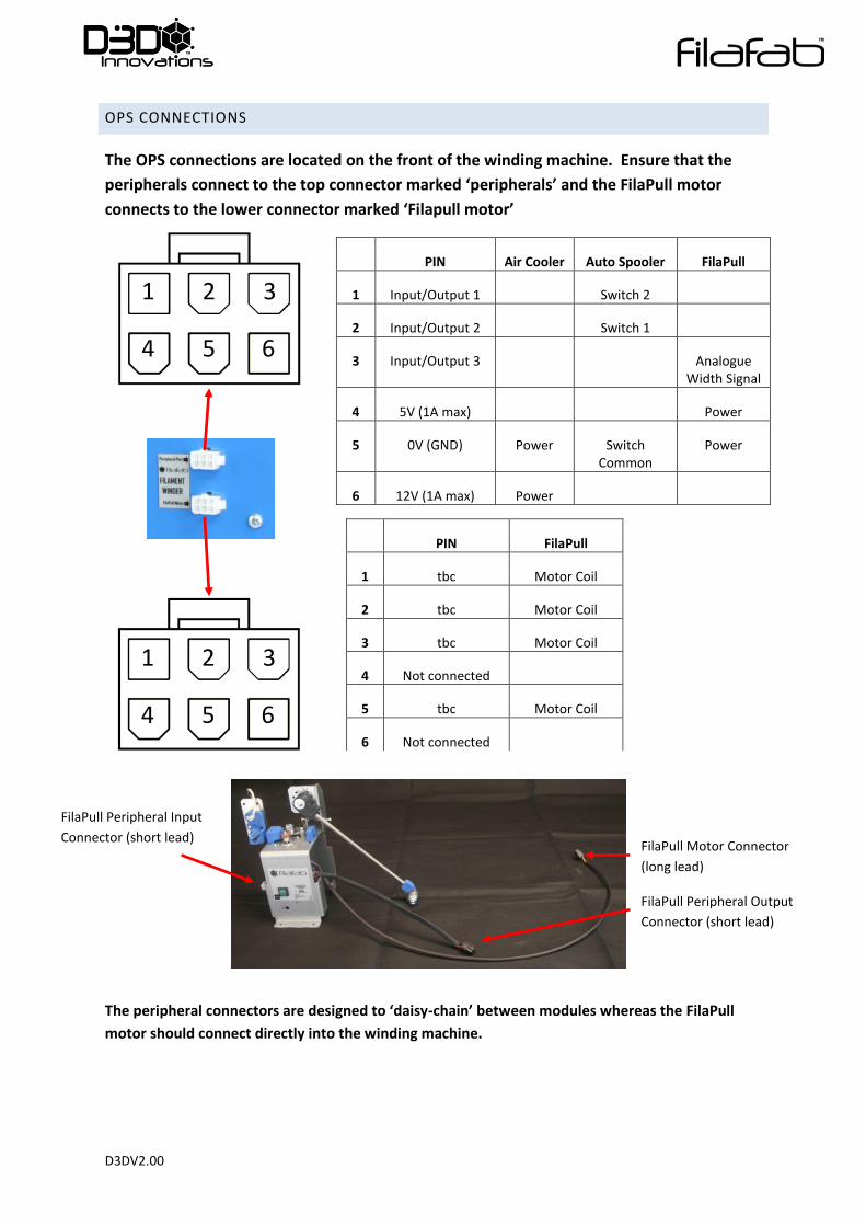
OPS CONNECTIONS
The OPS connections are located on the front of the winding machine. Ensure that the
peripherals connect to the top connector marked ‘peripherals’ and the FilaPull motor
connects to the lower connector marked ‘Filapull motor’
PIN Air Cooler Auto Spooler FilaPull
1 Input/Output 1 Switch 2
2 Input/Output 2 Switch 1
3 Input/Output 3 Analogue Width Signal
4 5V (1A max) Power
5 0V (GND) Power Switch Common
Power
6 12V (1A max) Power
The peripheral connectors are designed to ‘daisy-chain’ between modules whereas the FilaPull
motor should connect directly into the winding machine.
PIN FilaPull
1 tbc Motor Coil
2 tbc Motor Coil
3 tbc Motor Coil
4 Not connected
5 tbc Motor Coil
6 Not connected
1 2 3
4 5 6
1 2 3
4 5 6
FilaPull Motor Connector
(long lead)
FilaPull Peripheral Output
Connector (short lead)
FilaPull Peripheral Input
Connector (short lead)
D3DV2.00
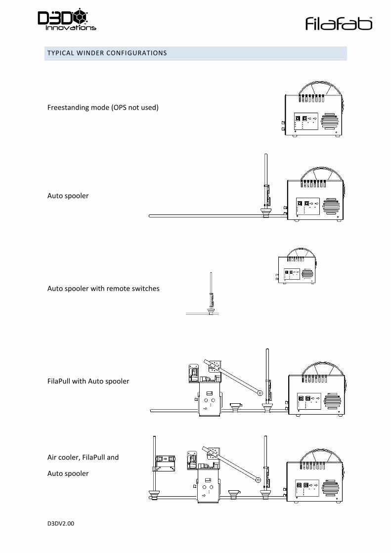
TYPICAL WINDER CONFIGURATIONS
Freestanding mode (OPS not used)
Auto spooler
Auto spooler with remote switches
FilaPull with Auto spooler
Air cooler, FilaPull and
Auto spooler
D3DV2.00
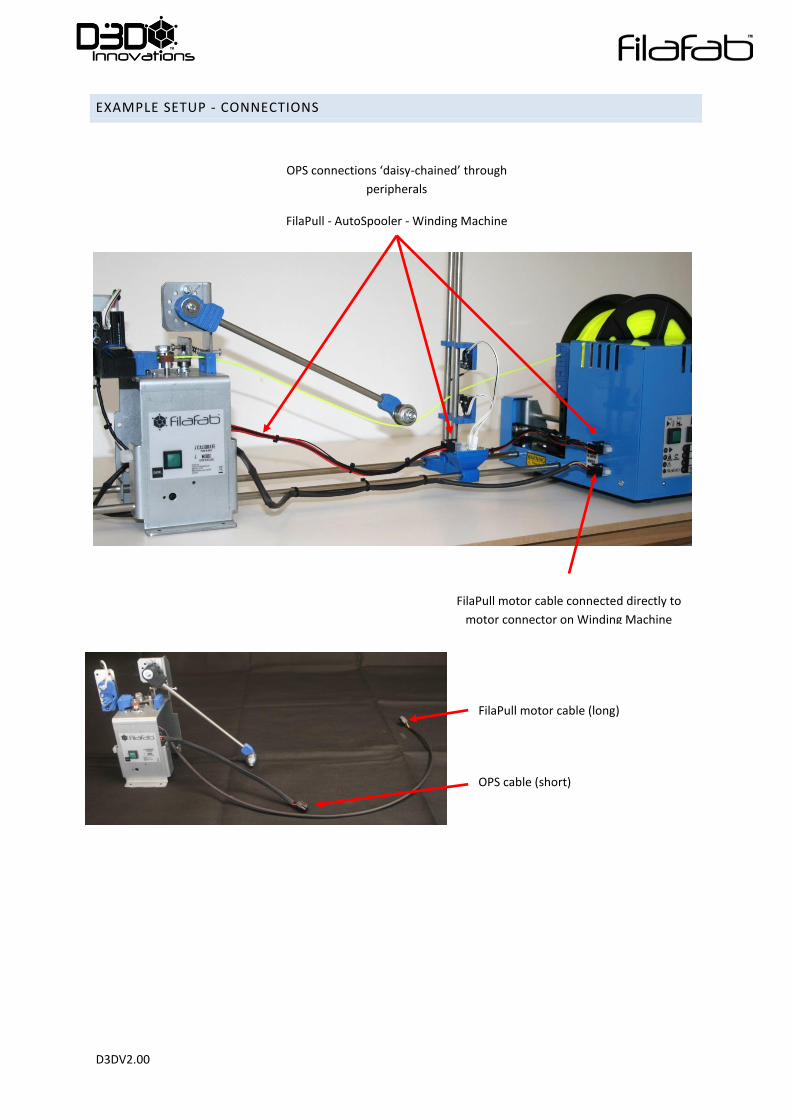
EXAMPLE SETUP - CONNECTIONS
OPS connections ‘daisy-chained’ through
peripherals
FilaPull - AutoSpooler - Winding Machine
FilaPull motor cable connected directly to
motor connector on Winding Machine
FilaPull motor cable (long)
OPS cable (short)
D3DV2.00
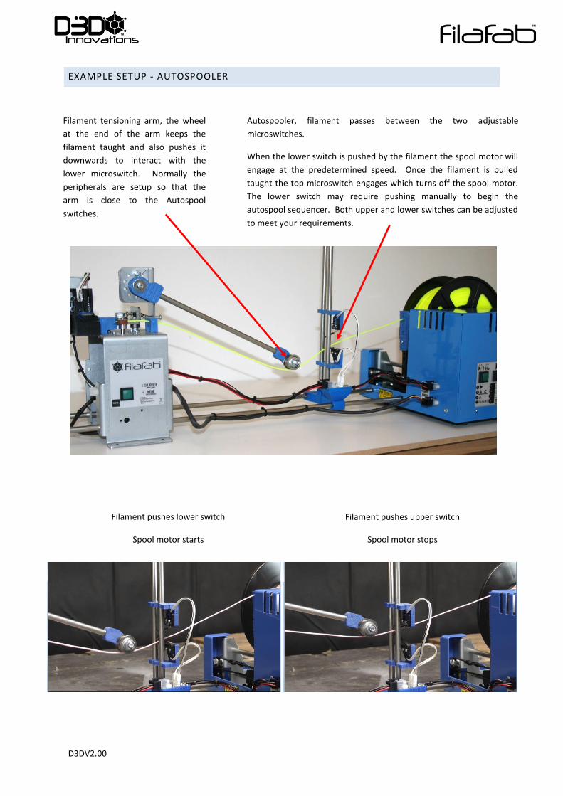
EXAMPLE SETUP - AUTOSPOOLER
Autospooler, filament passes between the two adjustable
microswitches.
When the lower switch is pushed by the filament the spool motor will
engage at the predetermined speed. Once the filament is pulled
taught the top microswitch engages which turns off the spool motor.
The lower switch may require pushing manually to begin the
autospool sequencer. Both upper and lower switches can be adjusted
to meet your requirements.
Filament pushes lower switch
Spool motor starts
Filament tensioning arm, the wheel
at the end of the arm keeps the
filament taught and also pushes it
downwards to interact with the
lower microswitch. Normally the
peripherals are setup so that the
arm is close to the Autospool
switches.
Filament pushes upper switch
Spool motor stops

D3DV2.00
CONNECT PERIPHERALS
Connect all required peripherals to the peripheral rail system and make all the piggy back
connections.
If a FilaPull is used then also connect the FilaPull motor connector to the motor connector
on the winder.
Note: Ensure that the OPS connections are made only to the OPS, do not connect to the
FilaPull motor connector. The FilaPull motor connector should be only connected to the
motor cable from FilaPull.
D3DV2.00
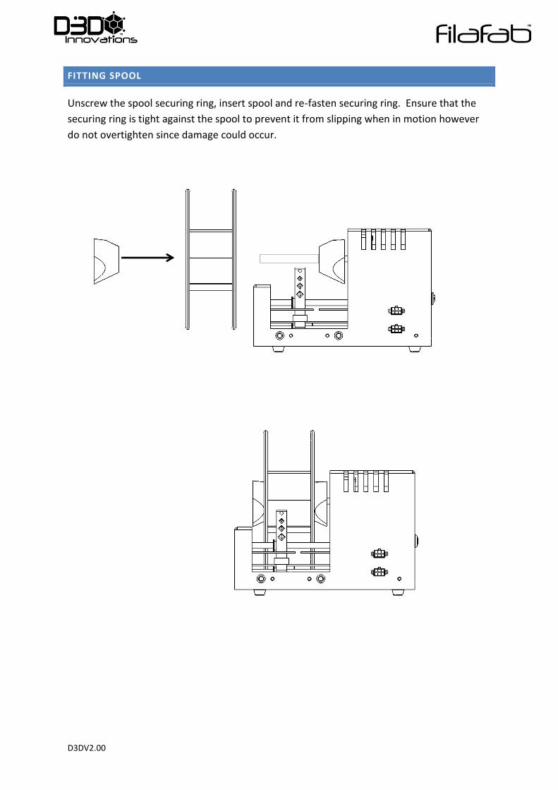
FITTING SPOOL
Unscrew the spool securing ring, insert spool and re-fasten securing ring. Ensure that the
securing ring is tight against the spool to prevent it from slipping when in motion however
do not overtighten since damage could occur.
D3DV2.00
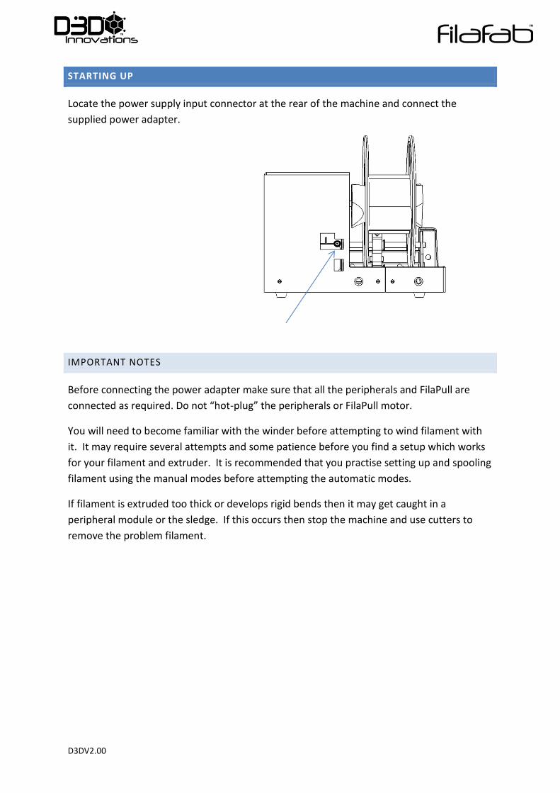
STARTING UP
Locate the power supply input connector at the rear of the machine and connect the
supplied power adapter.
IMPORTANT NOTES
Before connecting the power adapter make sure that all the peripherals and FilaPull are
connected as required. Do not “hot-plug” the peripherals or FilaPull motor.
You will need to become familiar with the winder before attempting to wind filament with
it. It may require several attempts and some patience before you find a setup which works
for your filament and extruder. It is recommended that you practise setting up and spooling
filament using the manual modes before attempting the automatic modes.
If filament is extruded too thick or develops rigid bends then it may get caught in a
peripheral module or the sledge. If this occurs then stop the machine and use cutters to
remove the problem filament.
D3DV2.00
SELECT MODE
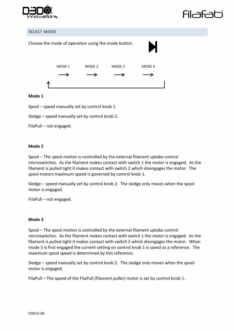
Choose the mode of operation using the mode button.
Mode 1
Spool – speed manually set by control knob 1.
Sledge – speed manually set by control knob 2.
FilaPull – not engaged.
Mode 2
Spool – The spool motion is controlled by the external filament uptake control microswitches. As the filament makes contact with switch 1 the motor is engaged. As the filament is pulled tight it makes contact with switch 2 which disengages the motor. The spool motors maximum speed is governed by control knob 1.
Sledge – speed manually set by control knob 2. The sledge only moves when the spool motor is engaged.
FilaPull – not engaged.
Mode 3
Spool – The spool motion is controlled by the external filament uptake control microswitches. As the filament makes contact with switch 1 the motor is engaged. As the filament is pulled tight it makes contact with switch 2 which disengages the motor. When mode 3 is first engaged the current setting on control knob 1 is saved as a reference. The maximum spool speed is determined by this reference.
Sledge – speed manually set by control knob 2. The sledge only moves when the spool motor is engaged.
FilaPull – The speed of the FilaPull (filament puller) motor is set by control knob 1.
MODE 1 MODE 2 MODE 3 MODE 4
D3DV2.00
Mode 4
Spool – The spool motion is controlled by the external filament uptake control
microswitches. As the filament makes contact with switch 1 the motor is engaged. As the
filament is pulled tight it makes contact with switch 2 which disengages the motor. When
mode 3 is engaged the current setting on control knob 1 is saved as a reference. The
maximum spool speed is determined by this reference.
Sledge – speed manually set by control knob 2. The sledge only moves when the spool
motor is engaged.
FilaPull - When mode 4 is engaged the instantaneous diameter of the filament is measured
and the result stored as a reference.
Changes to the diameter of the filament will be detected by the optical sensor by comparing
the stored reference with the current value. The system will then attempt to compensate
by increasing or reducing the FilaPull motor speed.
The rate at which the FilaPull speed changed is effected by the refresh rate. This is designed
to compensate for the distance between the nozzle and the sensor. Since a change at the
nozzle will not be detected until the filament moves along the line to the sensor.
USB Mode if supported
Only supported on selected devices selecting the mode beyond mode 4 will engage USB
mode. If none of the mode LED’s are illuminated then USB mode is selected. Pressing the
mode control button again will increment the mode back to mode 1.
if supported

D3DV2.00
START/PAUSE
Press the green go button to start or pause the winder
Note that the machine will not start until a sledge calibration has
been completed. See section above for details.
WINDING FILAMENT
The process will vary depending on which peripherals you have fitted and therefore only
typical setups are discussed.
Begin the extruder
Grab hold of the freshly extruded filament with a pair of pliers and guide it through the
peripheral systems.
Guide the filament through the sledge guide holes and then quickly secure it to the spool
using adhesive tape.
Quickly start the winder in manual mode 1 and set the spool speed appropriately.
Adjust the sledge speed to modify the way the filament is layered onto the spool as
required.
If the filament becomes jammed then immediately pause the spool motor by pressing the
green Go button. Once the jam has been removed then re-start.
Note: All filament will behave differently when extruded and wound. It may be necessary to
cool the filament prior to winding by using either one or more FilaFab Air Coolers or a
proprietary system such as a water bath.
Note: Some filaments can be heavy and may need additional supports to guide them along
the peripheral system correctly.
Tip: You should practise through trial and error in manual mode 1 to determine the optimal
winding speeds and how your filament behaves until you are ready to switch to the other
modes. It is likely that you will have to go back and change modes until you become more
familiar with the system. Make sure you have enough material available before you begin.
Tip: Ask someone for a helping hand. Ask other FilaFab users. Check our website/Youtube
channel for hints and demonstrations and please share. Thanks

D3DV2.00
NOTES
___________________________________________________________________________
___________________________________________________________________________
___________________________________________________________________________
___________________________________________________________________________
___________________________________________________________________________
___________________________________________________________________________
___________________________________________________________________________
___________________________________________________________________________
___________________________________________________________________________
___________________________________________________________________________
___________________________________________________________________________
___________________________________________________________________________
___________________________________________________________________________
___________________________________________________________________________
___________________________________________________________________________
___________________________________________________________________________
_________________________________________________________________________
No reproduction in any form of this manual, in whole or in part (except for brief quotation in articles
or reviews) may be made without written authorisation from D3D Innovations Limited.