Embed Size (px)
Citation preview
Figure: (REA, 2012)
The Living Toolbox CO2 Powered Race Car Resource Folio 1
This document has been developed in cooperation with Re-Engineering Australia. Re-Engineering
Australia Foundation was founded in 1998 by engineer, businessman and passionate Australian,
Dr Michael Myers OAM, in response to the drastic shortage of skilled young people wanting to
pursue engineering-technical-manufacturing career paths.
Dr Myers linked with forward-thinking companies, organisations, government departments,
educators and individuals who are passionate about enthusing, equipping and guiding our next
generation.
Many of the resources presented in this document have been developed by Re-Engineering
Australia and the authors of this document wish to acknowledge the fantastic contribution that
REA have had on the success of technology education throughout Australia.
The Technological Literacy Group through their Science of Speed web site also kindly allowed
the use of images and information for this document. The Technological literacy group is
dedicated to STEM education based in the USA it provides excellent resources for CO2 powered
racing.
Funding for the collation of this document has been provided by the ME program. This
program is about creating a path for high school students to experience and explore the
career opportunities that are possible in the manufacturing industry.
These opportunities are delivered through a school program tailored to students from
years 9-12. Schools provide core subjects like Mathematics, English, Science,
Information and Communication Technology and Engineering Studies to provide the
foundations for pursuing a career in manufacturing.
The ME program is sponsored by Regional Development Australia Hunter and the
Department of Defence, Defence Materiel Organisation.
The Living Toolbox is an initiative of the ME program which was developed
to provide hands-on resources to support teaching and learning of advance
manufacturing in our schools.
This document has been prepared by Mr Ces D’Amico and Mr Scott
Sleap from Maitland Grossmann High, East Maitland NSW, Australia.
Figure: (LAVC, 2012)
The Living Toolbox CO2 Powered Race Car Resource Folio 2
The Formula One Technology Challenge is an exciting, innovative and modern science, math and
engineering action learning activity. With hundreds of schools Australia-wide already active, the
F1inSchools program is ideal for all schools, being easy to integrate into a wide range of
curriculum areas, or as an extra curricula activity.
The competition revolves around teams designing making and racing C02 powered cars which
have been machined from a balsa block using Computer Aided Drafting and Computer Aided
Manufacturing techniques.
This resource is based on preparing students to compete in this competition through the delivery
of the NSW stage 5 Industrial Technology – Engineering syllabus. Although this is the aim of this
resource it is not necessary for the completion of this unit as a standalone engineering topic.
The Living Toolbox website has been developed in conjunction with the ME
program, to provide useful resources to assist teachers to effectively introduce
advanced manufacturing concepts in the classroom.
The ME program website has many resources for schools, industry and parents. It
has been designed to assist participants in the program to reach the objects of the
program.
Re-Engineering Foundation hold the Australian licence for the F1inScools program
and their web site and accompanying supportal has a vast array of resources which
support the F1inSchools Technology Challenge (REA, 2012).
The F1inSchool program is the world’s largest Science, Technology, Engineering &
Mathematics (STEM) Competition. It involves over nine million students from
17,000 schools in 31 nations.
The DMO is part of the Department of Defence. In 2011-12 the Australian
Government will spend more than $10 billion acquiring and sustaining military
equipment and services. The DMO are major sponsors of both the F1inSchools
and the ME programs.

The Living Toolbox CO2 Powered Race Car Resource Folio 3
Your Brief - You are the Formula One Team commissioned to design, construct and race the
fastest Formula One Car of the Future, driven by new compact compressed air power plants.
In order to complete this taks, you must work in a team of a minimum of 3 to a maximum of 6
persons, allocating job roles to the members of your group. Ideally, one role should be allocated to
each person. However, you may have to double up on your role and responsibilities, depending on
the number of people you have available.
The following job roles should be covered by the members of your team:
Team Manager (maximum 1 person). This person will be responsible
for managing the team, ensuring that the primary and back-up cars are ready
for the finals. The team manager works closely with all members of the team,
offering assistance where necessary.
Resources Manager (maximum 1 person). This person organises time,
materials and equipment for design and making the cars. They are also
responsible for developing ideas regarding team marketing (presentation).
The resources manager will need to liaise with all members to check tasks are
progressing on time and offer additional help, if needed.
Manufacturing Engineer (maximum 2 persons). These people are responsible for advising
team members on the manufacture of the car and the constraints of the
machining process. Manufacturing engineers will need to liaise with
the design engineers to report and help solve any problems with
construction of the car.
Design Engineer (maximum 2 persons). These people are responsible
for the styling and aerodynamic performance of the car design. Design
engineers will need to liaise with the manufacturing engineers to
ensure their ideas can be realised.
Graphic Designer (maximum 1 person). This person will be
responsible for producing the colour schemes applied to the vehicle, including
any special sponsorship decals, together with the final graphic renderings and
any additional team marketing materials. The graphic designer will need to
liaise with the design engineer to ensure any schemes will fit the shape of the
vehicle and the resources manager for additional marketing development.
There are so many tasks that must be mastered, in order to design, manufacture, prepare and
finally enter a car for racing, that teamwork will be vital to your success. A real F1 team
succeeds because all the people learn to work together and support each other. Remember, no
one person is more important than another (REA, 2012) .
The Living Toolbox CO2 Powered Race Car Resource Folio 4
One of the first tasks for this assessment task is to form into teams and assign roles. Firstly
you and your team members need to understand what their role is and what has to be
completed in each part of the process. HOWEVER, the best way to approach this project is
the team approach with all members assisting each other and some members leading the
work in the different areas. As you progress through the process, it will become apparent
that some team members have skills in different areas and roles can be allocated
accordingly.
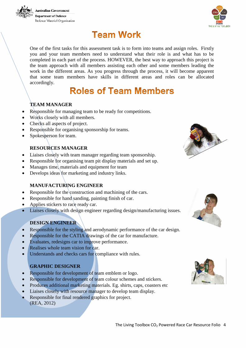
TEAM MANAGER
Responsible for managing team to be ready for competitions.
Works closely with all members.
Checks all aspects of project.
Responsible for organising sponsorship for teams.
Spokesperson for team.
RESOURCES MANAGER
Liaises closely with team manager regarding team sponsorship.
Responsible for organising team pit display materials and set up.
Manages time, materials and equipment for team
Develops ideas for marketing and industry links.
MANUFACTURING ENGINEER
Responsible for the construction and machining of the cars.
Responsible for hand sanding, painting finish of car.
Applies stickers to race ready car.
Liaises closely with design engineer regarding design/manufacturing issues.
DESIGN ENGINEER
Responsible for the styling and aerodynamic performance of the car design.
Responsible for the CATIA drawings of the car for manufacture.
Evaluates, redesigns car to improve performance.
Realises whole team vision for car.
Understands and checks cars for compliance with rules.
GRAPHIC DESIGNER
Responsible for development of team emblem or logo.
Responsible for development of team colour schemes and stickers.
Produces additional marketing materials. Eg. shirts, caps, coasters etc
Liaises closely with resource manager to develop team display.
Responsible for final rendered graphics for project.
(REA, 2012)
The Living Toolbox CO2 Powered Race Car Resource Folio 5
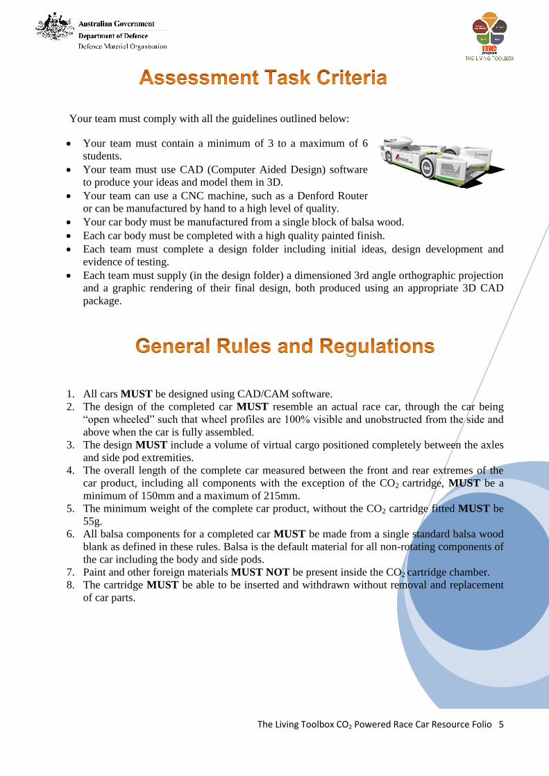
Your team must comply with all the guidelines outlined below:
Your team must contain a minimum of 3 to a maximum of 6
students.
Your team must use CAD (Computer Aided Design) software
to produce your ideas and model them in 3D.
Your team can use a CNC machine, such as a Denford Router
or can be manufactured by hand to a high level of quality.
Your car body must be manufactured from a single block of balsa wood.
Each car body must be completed with a high quality painted finish.
Each team must complete a design folder including initial ideas, design development and
evidence of testing.
Each team must supply (in the design folder) a dimensioned 3rd angle orthographic projection
and a graphic rendering of their final design, both produced using an appropriate 3D CAD
package.
1. All cars MUST be designed using CAD/CAM software.
2. The design of the completed car MUST resemble an actual race car, through the car being
“open wheeled” such that wheel profiles are 100% visible and unobstructed from the side and
above when the car is fully assembled.
3. The design MUST include a volume of virtual cargo positioned completely between the axles
and side pod extremities.
4. The overall length of the complete car measured between the front and rear extremes of the
car product, including all components with the exception of the CO2 cartridge, MUST be a
minimum of 150mm and a maximum of 215mm.
5. The minimum weight of the complete car product, without the CO2 cartridge fitted MUST be
55g.
6. All balsa components for a completed car MUST be made from a single standard balsa wood
blank as defined in these rules. Balsa is the default material for all non-rotating components of
the car including the body and side pods.
7. Paint and other foreign materials MUST NOT be present inside the CO2 cartridge chamber.
8. The cartridge MUST be able to be inserted and withdrawn without removal and replacement
of car parts.
The Living Toolbox CO2 Powered Race Car Resource Folio 6
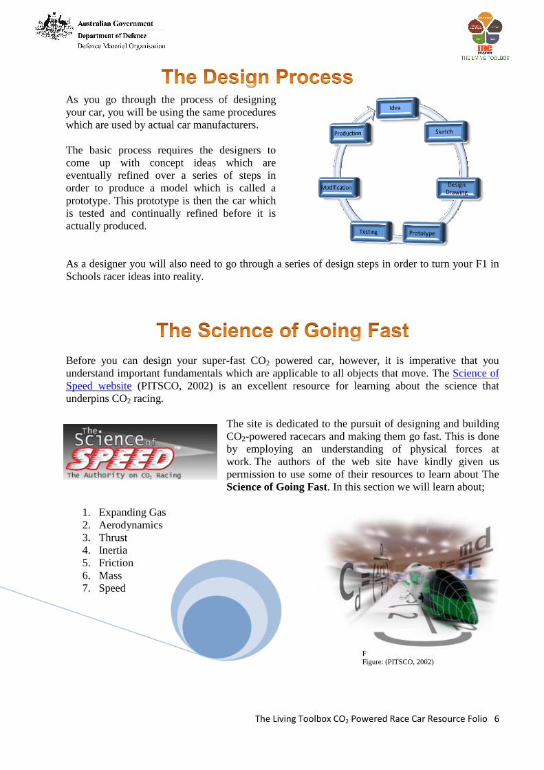
As you go through the process of designing
your car, you will be using the same procedures
which are used by actual car manufacturers.
The basic process requires the designers to
come up with concept ideas which are
eventually refined over a series of steps in
order to produce a model which is called a
prototype. This prototype is then the car which
is tested and continually refined before it is
actually produced.
As a designer you will also need to go through a series of design steps in order to turn your F1 in
Schools racer ideas into reality.
Before you can design your super-fast CO2 powered car, however, it is imperative that you
understand important fundamentals which are applicable to all objects that move. The Science of
Speed website (PITSCO, 2002) is an excellent resource for learning about the science that
underpins CO2 racing.
The site is dedicated to the pursuit of designing and building
CO2-powered racecars and making them go fast. This is done
by employing an understanding of physical forces at
work. The authors of the web site have kindly given us
permission to use some of their resources to learn about The
Science of Going Fast. In this section we will learn about;
1. Expanding Gas
2. Aerodynamics
3. Thrust
4. Inertia
5. Friction
6. Mass
7. Speed
F
ig
F
FFigure: (PITSCO, 2002)
The Living Toolbox CO2 Powered Race Car Resource Folio 7
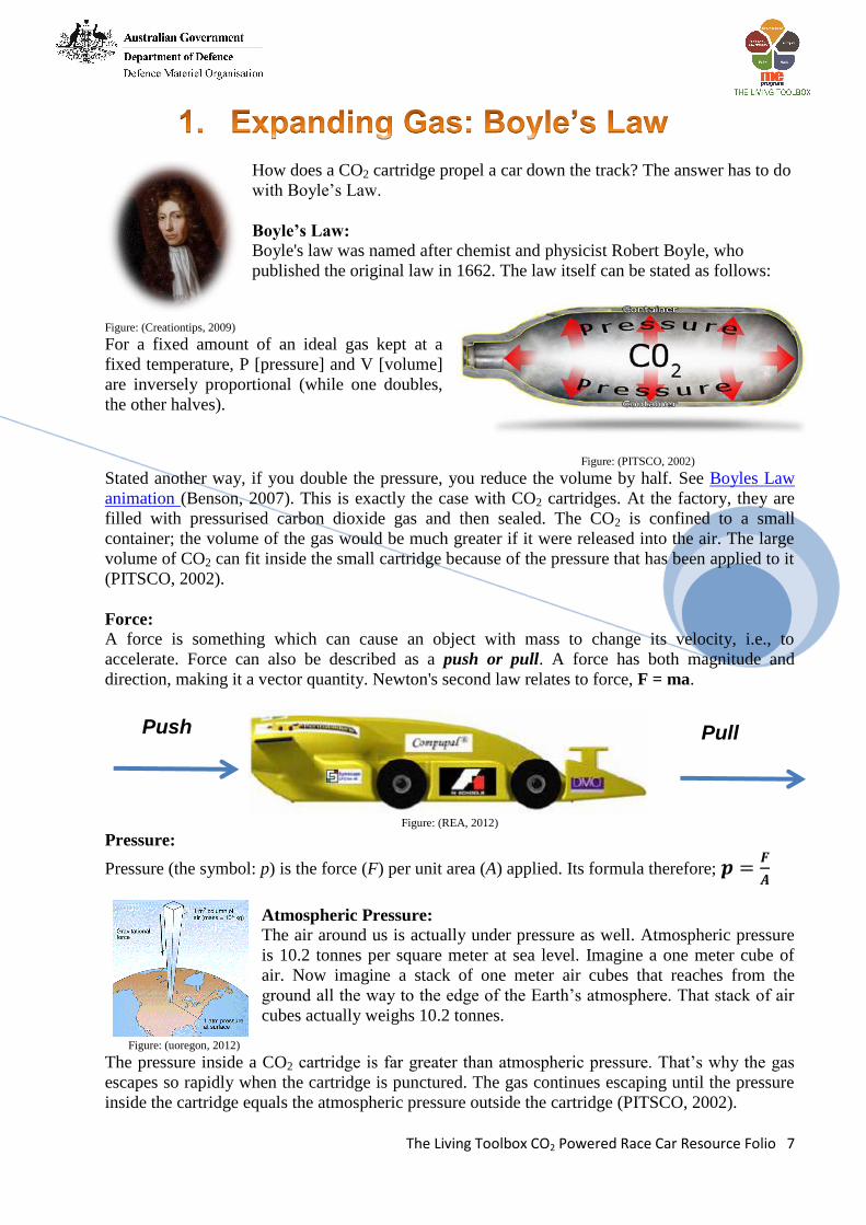
How does a CO2 cartridge propel a car down the track? The answer has to do
with Boyle’s Law.
Boyle’s Law:
Boyle's law was named after chemist and physicist Robert Boyle, who
published the original law in 1662. The law itself can be stated as follows:
Figure: (Creationtips, 2009)
For a fixed amount of an ideal gas kept at a
fixed temperature, P [pressure] and V [volume]
are inversely proportional (while one doubles,
the other halves).
Figure: (PITSCO, 2002)
Stated another way, if you double the pressure, you reduce the volume by half. See Boyles Law
animation (Benson, 2007). This is exactly the case with CO2 cartridges. At the factory, they are
filled with pressurised carbon dioxide gas and then sealed. The CO2 is confined to a small
container; the volume of the gas would be much greater if it were released into the air. The large
volume of CO2 can fit inside the small cartridge because of the pressure that has been applied to it
(PITSCO, 2002).
Force:
A force is something which can cause an object with mass to change its velocity, i.e., to
accelerate. Force can also be described as a push or pull. A force has both magnitude and
direction, making it a vector quantity. Newton's second law relates to force, F = ma.
Figure: (REA, 2012)
Pressure:
Pressure (the symbol: p) is the force (F) per unit area (A) applied. Its formula therefore;
Atmospheric Pressure:
The air around us is actually under pressure as well. Atmospheric pressure
is 10.2 tonnes per square meter at sea level. Imagine a one meter cube of
air. Now imagine a stack of one meter air cubes that reaches from the
ground all the way to the edge of the Earth’s atmosphere. That stack of air
cubes actually weighs 10.2 tonnes.
Figure: (uoregon, 2012)
The pressure inside a CO2 cartridge is far greater than atmospheric pressure. That’s why the gas
escapes so rapidly when the cartridge is punctured. The gas continues escaping until the pressure
inside the cartridge equals the atmospheric pressure outside the cartridge (PITSCO, 2002).
Push Pull
The Living Toolbox CO2 Powered Race Car Resource Folio 8
Aerodynamics is the study of moving air and the forces that it produces. People who design things
that move through the air, or have air move past them need to be familiar with aerodynamics. The
study of airflow and the forces involved when an object moves through the air, or when air moves
past an object is called aerodynamics.
It is a fascinating subject as the forces that are
generated can be large enough to enable
extremely heavy objects such as a jumbo jet
lift off the ground and to be supported by what
would seem to be only thin air.
The Wright brothers were the first people to
design what we would consider to be a plane.
Their designs on gliders and then for the first
motorised flight became possible not only
because of the experimentation they conducted
in trialling gliders but also because of their
experimentation that they carried out in the
first wind tunnels. Figure: (old-picture.com, 2006-2008)
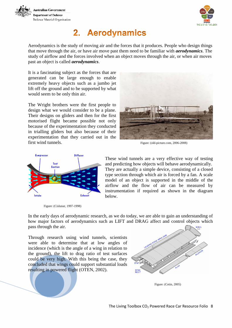
These wind tunnels are a very effective way of testing
and predicting how objects will behave aerodynamically.
They are actually a simple device, consisting of a closed
type section through which air is forced by a fan. A scale
model of an object is supported in the middle of the
airflow and the flow of air can be measured by
instrumentation if required as shown in the diagram
below.
Figure: (Cislunar, 1997-1998)
In the early days of aerodynamic research, as we do today, we are able to gain an understanding of
how major factors of aerodynamics such as LIFT and DRAG affect and control objects which
pass through the air.
Through research using wind tunnels, scientists
were able to determine that at low angles of
incidence (which is the angle of a wing in relation to
the ground), the lift to drag ratio of test surfaces
could be very high. With this being the case, they
concluded that wings could support substantial loads
resulting in powered flight (OTEN, 2002).
Figure: (Cetin, 2005)

The Living Toolbox CO2 Powered Race Car Resource Folio 9
They also discovered that the shape of wings determined the
amount of lift that they could provide. Long narrow wings are
able to provide more lift than short stubby wings of the same
area.
In order to make all of this research worthwhile, researches had
to solve the problem of how all of this research of airflow in
scale models was related to full scale aircraft cars etc. Figure: (Illusionist, 2011)
Osborne Reynolds was one such researcher and he demonstrated that the airflow
pattern over a scale model would be the same as that on a full scale version if the
flow parameters were the same. Reynolds demonstrated that the motion of a fluid
may be either laminar or turbulent.
Figure: (Collier, 1904)
Aerodynamics is widely studied in motor sport and in particular Formula 1 Racing.
Projected Frontal Area
The first important thing to know about aerodynamics is “Projected
Frontal Area.” As your car rolls down the track and through the air
it moves air out of its way. Projected frontal area is a measurement
in square units that describes how much air an object moves as it
travels. Think of it as the size of the hole that your car pokes
through the air as it goes (REA, 2012).
Figure: (REA, 2012)
Types of Airflow
As Reynolds discovered there are two types of air flow; laminar and turbulent.
Laminar flow is when the air flowing around
an object remains relatively smooth. The air
flows in layers that never cross each other. In
a wind tunnel sometimes tracks of smoke-like
vapour are used to visualize the flow of air
over an object. Where the tracks of vapour
stay parallel to each other, there is laminar flow. Figure: (Barker, 2012)
Turbulent flow is airflow resulting from the breakup of laminar flow, resulting in tumbling,
swirling or violently agitated motion. In a
wind tunnel using the vapour tracks,
turbulence shows up when the smoke swirls
or dissipates. Turbulent flow is created when
the direction of laminar air flow is changed
too drastically, and/or flows past an edge or
corner of an object (Barker, 2012). Figure: (Barker, 2012)
The Living Toolbox CO2 Powered Race Car Resource Folio 10
See it in Action
Sometimes when engineers use a wind tunnel
they tape small lengths of ribbon at different
places on the object being tested. The ribbon is
taped down at the front end and left free at the
other end. If the ribbon stays straight when air
flows over the object, laminar flow is present at
that point. If the tape flaps around wildly, then
turbulent flow is present at that point. Click on
the "wind tunnel" link to view a video of a model
truck in a wind tunnel.
Aerodynamics in Racing
We now know that aerodynamics is the science that
studies objects moving through air. It is closely related
to fluid dynamics as air is considered a compressible
fluid. Nowadays, aerodynamics is the utmost important
factor in Formula 1 car performance. It has even nearly
become one of the only aspects of performance gain due
to the very marginal gains that can currently be made by
engine changes or other mechanic component development. This down force can be likened to a
"virtual" increase in weight, pressing the car down onto the road and increasing the available
frictional force between the car and the road, therefore enabling higher cornering speeds.
Computational Fluid Dynamic Systems (CFD)
Furthermore, as Formula 1 teams have the greatest resources
to develop aero efficiency of its cars, the greatest strives are
made here. F1 teams have unrivalled CFD computing power
and at least one full time wind tunnel only for validating and
improving their designs.
Figure: (DENFORD, 2012)
While basic aerodynamic methods and formulas can be simply resolved, other properties are
verifiable with empirical formulas. More complex shapes such as airplanes or racing cars are,
however, impossible to calculate precisely, rendering computational fluid dynamic systems (CFD
applications on super computers) and wind tunnels an absolute requirement to validate designs.
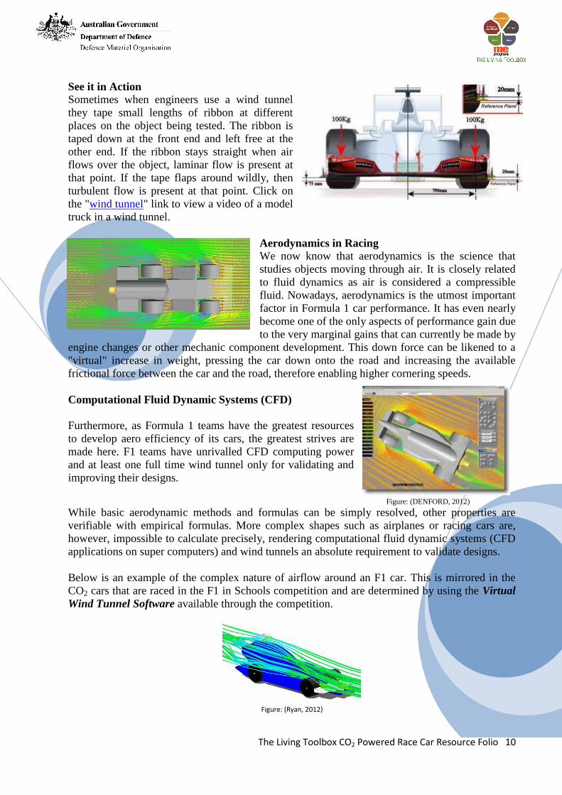
Below is an example of the complex nature of airflow around an F1 car. This is mirrored in the
CO2 cars that are raced in the F1 in Schools competition and are determined by using the Virtual
Wind Tunnel Software available through the competition.
Figure: (Ryan, 2012)
The Living Toolbox CO2 Powered Race Car Resource Folio 11
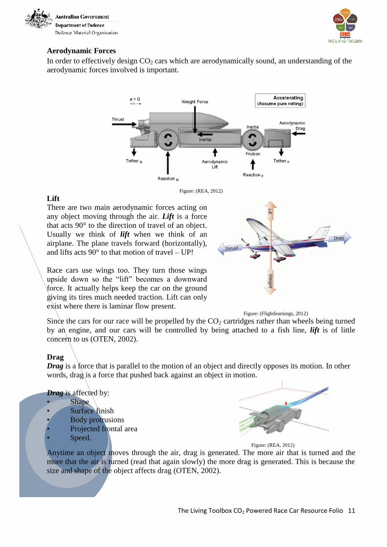
Aerodynamic Forces
In order to effectively design CO2 cars which are aerodynamically sound, an understanding of the
aerodynamic forces involved is important.
Figure: (REA, 2012)
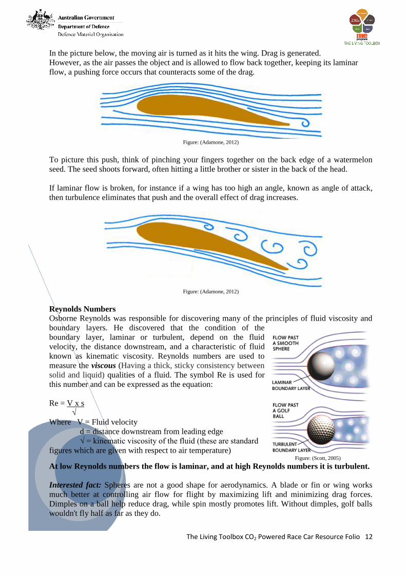
Lift There are two main aerodynamic forces acting on
any object moving through the air. Lift is a force
that acts 90° to the direction of travel of an object.
Usually we think of lift when we think of an
airplane. The plane travels forward (horizontally),
and lifts acts 90° to that motion of travel – UP!
Race cars use wings too. They turn those wings
upside down so the “lift” becomes a downward
force. It actually helps keep the car on the ground
giving its tires much needed traction. Lift can only
exist where there is laminar flow present. Figure: (Flightlearnings, 2012)
Since the cars for our race will be propelled by the CO2 cartridges rather than wheels being turned
by an engine, and our cars will be controlled by being attached to a fish line, lift is of little
concern to us (OTEN, 2002).
Drag
Drag is a force that is parallel to the motion of an object and directly opposes its motion. In other
words, drag is a force that pushed back against an object in motion.
Drag is affected by:
• Shape
• Surface finish
• Body protrusions
• Projected frontal area
• Speed. Figure: (REA, 2012)
Anytime an object moves through the air, drag is generated. The more air that is turned and the
more that the air is turned (read that again slowly) the more drag is generated. This is because the
size and shape of the object affects drag (OTEN, 2002).
The Living Toolbox CO2 Powered Race Car Resource Folio 12
In the picture below, the moving air is turned as it hits the wing. Drag is generated.
However, as the air passes the object and is allowed to flow back together, keeping its laminar
flow, a pushing force occurs that counteracts some of the drag.
Figure: (Adamone, 2012)
To picture this push, think of pinching your fingers together on the back edge of a watermelon
seed. The seed shoots forward, often hitting a little brother or sister in the back of the head.
If laminar flow is broken, for instance if a wing has too high an angle, known as angle of attack,
then turbulence eliminates that push and the overall effect of drag increases.
Figure: (Adamone, 2012)
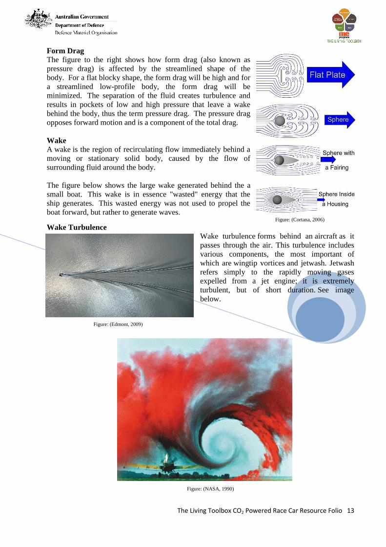
Reynolds Numbers
Osborne Reynolds was responsible for discovering many of the principles of fluid viscosity and
boundary layers. He discovered that the condition of the
boundary layer, laminar or turbulent, depend on the fluid
velocity, the distance downstream, and a characteristic of fluid
known as kinematic viscosity. Reynolds numbers are used to
measure the viscous (Having a thick, sticky consistency between
solid and liquid) qualities of a fluid. The symbol Re is used for
this number and can be expressed as the equation:
Re = V x s
√
Where V = Fluid velocity
d = distance downstream from leading edge
√ = kinematic viscosity of the fluid (these are standard
figures which are given with respect to air temperature) Figure: (Scott, 2005)
At low Reynolds numbers the flow is laminar, and at high Reynolds numbers it is turbulent.
Interested fact: Spheres are not a good shape for aerodynamics. A blade or fin or wing works
much better at controlling air flow for flight by maximizing lift and minimizing drag forces.
Dimples on a ball help reduce drag, while spin mostly promotes lift. Without dimples, golf balls
wouldn't fly half as far as they do.
Test
Test
The Living Toolbox CO2 Powered Race Car Resource Folio 13
Form Drag
The figure to the right shows how form drag (also known as
pressure drag) is affected by the streamlined shape of the
body. For a flat blocky shape, the form drag will be high and for
a streamlined low-profile body, the form drag will be
minimized. The separation of the fluid creates turbulence and
results in pockets of low and high pressure that leave a wake
behind the body, thus the term pressure drag. The pressure drag
opposes forward motion and is a component of the total drag.
Wake
A wake is the region of recirculating flow immediately behind a
moving or stationary solid body, caused by the flow of
surrounding fluid around the body.
The figure below shows the large wake generated behind the a
small boat. This wake is in essence "wasted" energy that the
ship generates. This wasted energy was not used to propel the
boat forward, but rather to generate waves. Figure: (Cortana, 2006)
Wake Turbulence
Wake turbulence forms behind an aircraft as it
passes through the air. This turbulence includes
various components, the most important of
which are wingtip vortices and jetwash. Jetwash
refers simply to the rapidly moving gases
expelled from a jet engine; it is extremely
turbulent, but of short duration. See image
below.
Figure: (Edmont, 2009)
Figure: (NASA, 1990)
The Living Toolbox CO2 Powered Race Car Resource Folio 14
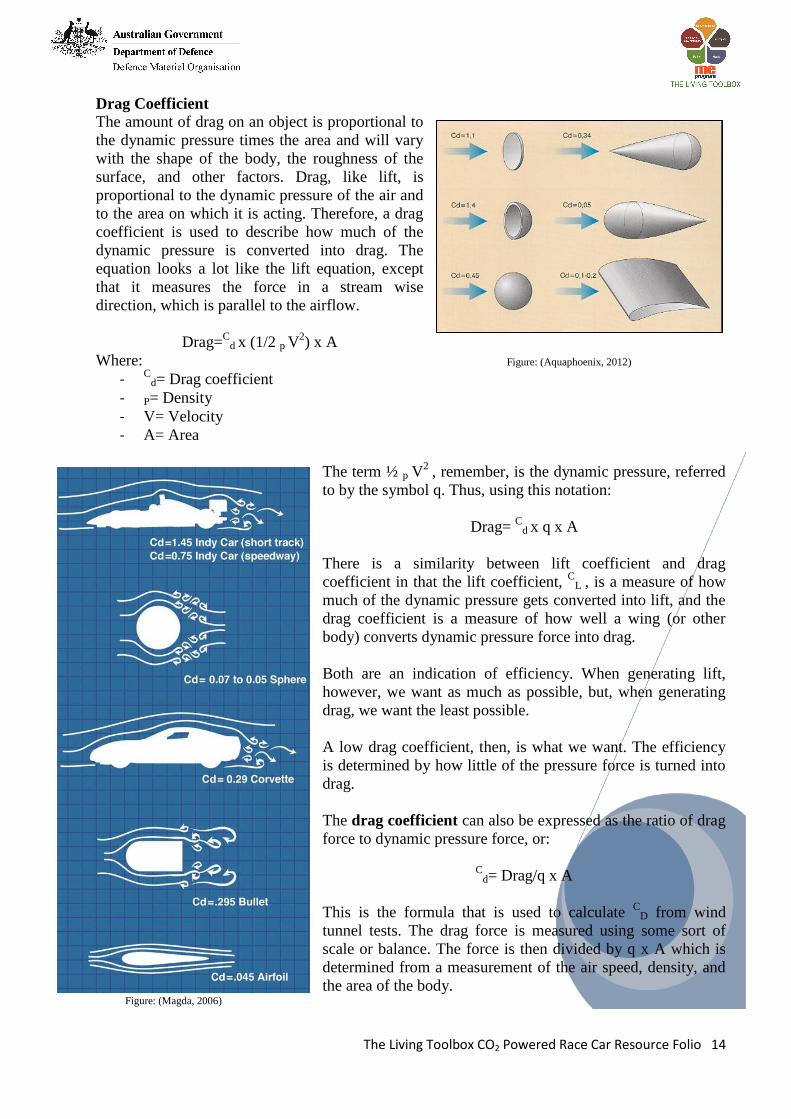
Drag Coefficient
The amount of drag on an object is proportional to
the dynamic pressure times the area and will vary
with the shape of the body, the roughness of the
surface, and other factors. Drag, like lift, is
proportional to the dynamic pressure of the air and
to the area on which it is acting. Therefore, a drag
coefficient is used to describe how much of the
dynamic pressure is converted into drag. The
equation looks a lot like the lift equation, except
that it measures the force in a stream wise
direction, which is parallel to the airflow.
Drag=C
d x (1/2 p V2) x A
Where: Figure: (Aquaphoenix, 2012)
- Cd= Drag coefficient
- P= Density
- V= Velocity
- A= Area
The term ½ p V2
, remember, is the dynamic pressure, referred
to by the symbol q. Thus, using this notation:
Drag= C
d x q x A
There is a similarity between lift coefficient and drag
coefficient in that the lift coefficient, C
L , is a measure of how
much of the dynamic pressure gets converted into lift, and the
drag coefficient is a measure of how well a wing (or other
body) converts dynamic pressure force into drag.
Both are an indication of efficiency. When generating lift,
however, we want as much as possible, but, when generating
drag, we want the least possible.
A low drag coefficient, then, is what we want. The efficiency
is determined by how little of the pressure force is turned into
drag.
The drag coefficient can also be expressed as the ratio of drag
force to dynamic pressure force, or:
C
d= Drag/q x A
This is the formula that is used to calculate C
D from wind
tunnel tests. The drag force is measured using some sort of
scale or balance. The force is then divided by q x A which is
determined from a measurement of the air speed, density, and
the area of the body. Figure: (Magda, 2006)
The Living Toolbox CO2 Powered Race Car Resource Folio 15
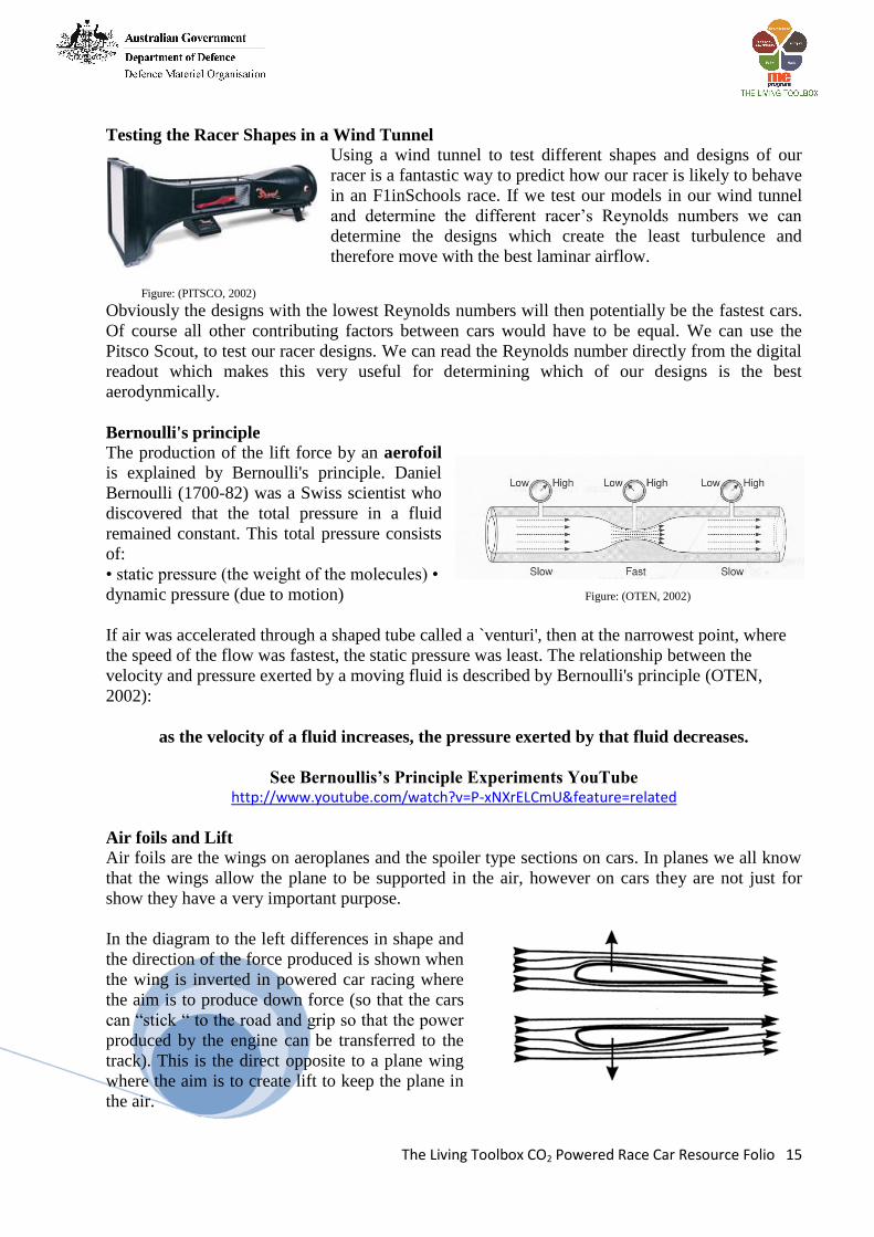
Testing the Racer Shapes in a Wind Tunnel
Using a wind tunnel to test different shapes and designs of our
racer is a fantastic way to predict how our racer is likely to behave
in an F1inSchools race. If we test our models in our wind tunnel
and determine the different racer’s Reynolds numbers we can
determine the designs which create the least turbulence and
therefore move with the best laminar airflow.
Figure: (PITSCO, 2002)
Obviously the designs with the lowest Reynolds numbers will then potentially be the fastest cars.
Of course all other contributing factors between cars would have to be equal. We can use the
Pitsco Scout, to test our racer designs. We can read the Reynolds number directly from the digital
readout which makes this very useful for determining which of our designs is the best
aerodynmically.
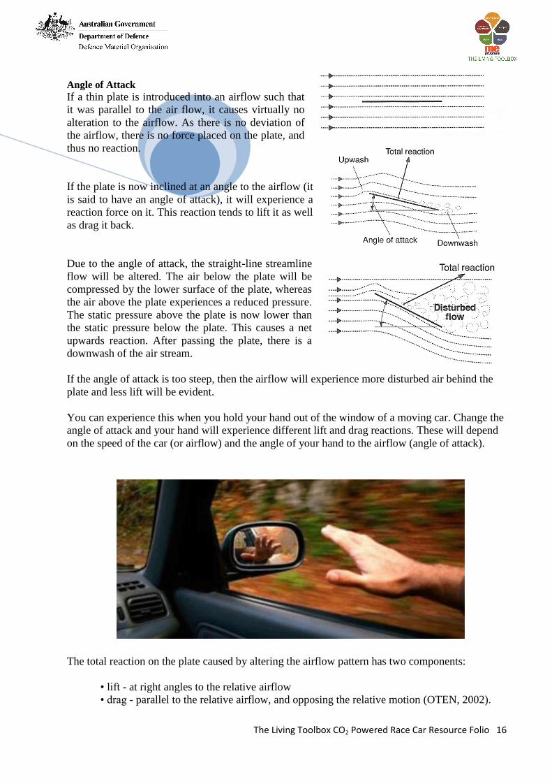
Bernoulli's principle
The production of the lift force by an aerofoil
is explained by Bernoulli's principle. Daniel
Bernoulli (1700-82) was a Swiss scientist who
discovered that the total pressure in a fluid
remained constant. This total pressure consists
of:
• static pressure (the weight of the molecules) •
dynamic pressure (due to motion) Figure: (OTEN, 2002)
If air was accelerated through a shaped tube called a `venturi', then at the narrowest point, where
the speed of the flow was fastest, the static pressure was least. The relationship between the
velocity and pressure exerted by a moving fluid is described by Bernoulli's principle (OTEN,
2002):
as the velocity of a fluid increases, the pressure exerted by that fluid decreases.
See Bernoullis’s Principle Experiments YouTube http://www.youtube.com/watch?v=P-xNXrELCmU&feature=related
Air foils and Lift
Air foils are the wings on aeroplanes and the spoiler type sections on cars. In planes we all know
that the wings allow the plane to be supported in the air, however on cars they are not just for
show they have a very important purpose.
In the diagram to the left differences in shape and
the direction of the force produced is shown when
the wing is inverted in powered car racing where
the aim is to produce down force (so that the cars
can “stick “ to the road and grip so that the power
produced by the engine can be transferred to the
track). This is the direct opposite to a plane wing
where the aim is to create lift to keep the plane in
the air.
The Living Toolbox CO2 Powered Race Car Resource Folio 16
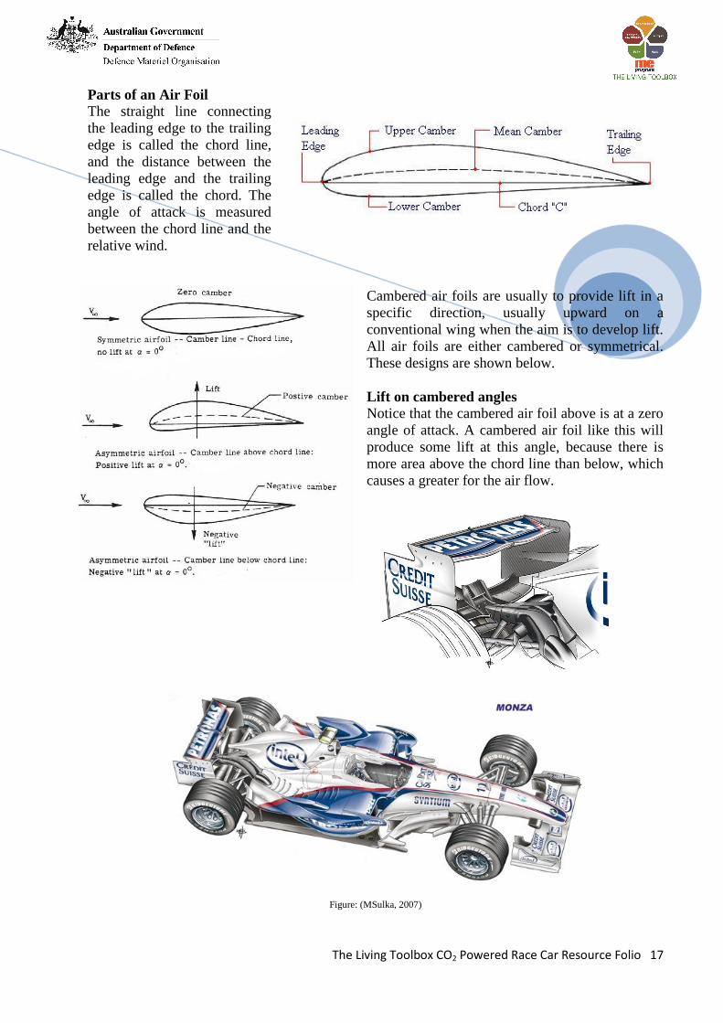
Angle of Attack
If a thin plate is introduced into an airflow such that
it was parallel to the air flow, it causes virtually no
alteration to the airflow. As there is no deviation of
the airflow, there is no force placed on the plate, and
thus no reaction.
If the plate is now inclined at an angle to the airflow (it
is said to have an angle of attack), it will experience a
reaction force on it. This reaction tends to lift it as well
as drag it back.
Due to the angle of attack, the straight-line streamline
flow will be altered. The air below the plate will be
compressed by the lower surface of the plate, whereas
the air above the plate experiences a reduced pressure.
The static pressure above the plate is now lower than
the static pressure below the plate. This causes a net
upwards reaction. After passing the plate, there is a
downwash of the air stream.
If the angle of attack is too steep, then the airflow will experience more disturbed air behind the
plate and less lift will be evident.
You can experience this when you hold your hand out of the window of a moving car. Change the
angle of attack and your hand will experience different lift and drag reactions. These will depend
on the speed of the car (or airflow) and the angle of your hand to the airflow (angle of attack).
The total reaction on the plate caused by altering the airflow pattern has two components:
• lift - at right angles to the relative airflow
• drag - parallel to the relative airflow, and opposing the relative motion (OTEN, 2002).
The Living Toolbox CO2 Powered Race Car Resource Folio 17
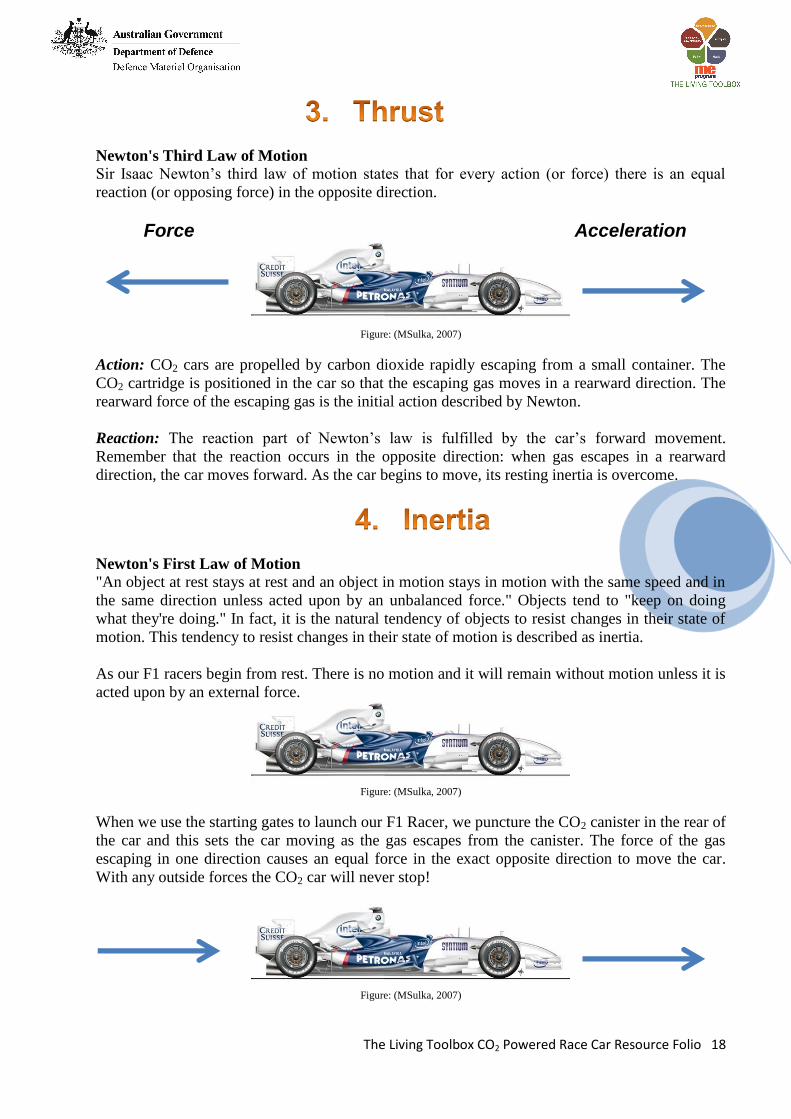
Parts of an Air Foil
The straight line connecting
the leading edge to the trailing
edge is called the chord line,
and the distance between the
leading edge and the trailing
edge is called the chord. The
angle of attack is measured
between the chord line and the
relative wind.
Cambered air foils are usually to provide lift in a
specific direction, usually upward on a
conventional wing when the aim is to develop lift.
All air foils are either cambered or symmetrical.
These designs are shown below.
Lift on cambered angles
Notice that the cambered air foil above is at a zero
angle of attack. A cambered air foil like this will
produce some lift at this angle, because there is
more area above the chord line than below, which
causes a greater for the air flow.
Figure: (MSulka, 2007)
The Living Toolbox CO2 Powered Race Car Resource Folio 18
Newton's Third Law of Motion
Sir Isaac Newton’s third law of motion states that for every action (or force) there is an equal
reaction (or opposing force) in the opposite direction.
Force Acceleration
Figure: (MSulka, 2007)
Action: CO2 cars are propelled by carbon dioxide rapidly escaping from a small container. The
CO2 cartridge is positioned in the car so that the escaping gas moves in a rearward direction. The
rearward force of the escaping gas is the initial action described by Newton.
Reaction: The reaction part of Newton’s law is fulfilled by the car’s forward movement.
Remember that the reaction occurs in the opposite direction: when gas escapes in a rearward
direction, the car moves forward. As the car begins to move, its resting inertia is overcome.
Newton's First Law of Motion
"An object at rest stays at rest and an object in motion stays in motion with the same speed and in
the same direction unless acted upon by an unbalanced force." Objects tend to "keep on doing
what they're doing." In fact, it is the natural tendency of objects to resist changes in their state of
motion. This tendency to resist changes in their state of motion is described as inertia.
As our F1 racers begin from rest. There is no motion and it will remain without motion unless it is
acted upon by an external force.
Figure: (MSulka, 2007)
When we use the starting gates to launch our F1 Racer, we puncture the CO2 canister in the rear of
the car and this sets the car moving as the gas escapes from the canister. The force of the gas
escaping in one direction causes an equal force in the exact opposite direction to move the car.
With any outside forces the CO2 car will never stop!
Figure: (MSulka, 2007)

The Living Toolbox CO2 Powered Race Car Resource Folio 19
The tendency to resist changes in their state of motion is described as inertia.
Inertia
Inertia is the resistance of any physical object to a change in its state of motion or rest, or the
tendency of an object to resist any change in its motion. In other words the greater the mass of
your CO2 car, the more energy required to get the car moving. If two cars use the same amount of
propulsive energy, the car with the lower mass will accelerate faster.
CO2 racers through the eyes of
Newton
In a CO2 car race, the dragster begins at
rest. There is no motion. According to
Newtons first law, it will remain at rest
until and outside force acts upon it. Figure: (Holden, 2011)
When the starting mechanism is activated the CO2 cartridge is punctured, many types of outside
forces will begin working on the car.
First of all, when the cartridge is punctured, the pressurized gas inside begins to escape from the
hole in the cartridge. The action of the CO2 gas escaping out the back of the cartridge (according
to Newton’s third law) causes an equal and opposite reaction – which is to move the dragster in
the opposite (forward) direction.
Figure: (Holden, 2011)
This equal and opposite reaction creates a force that pushes the car forward. The force continues
acting until the CO2 gas in the cartridge has been exhausted. According to Newton’s second law,
the acceleration of an object is inversely proportional to its mass when force is constant. That
means that if the amount of force is equal for each cartridge (which it is), then the more mass the
dragster has, the less acceleration.
The greatest determining factor for the success of a CO2 car is its mass. It is critical that the mass
of the car be as close to the minimum mass as possible. That will provide the greatest amount of
acceleration.
There are forces at work besides that of the racer being propelled forward, constantly trying to
slow the racer down. These are FRICTION and AERODYNAMIC DRAG. The sum of all of
these forces acting on the racer is termed the “net force” (Holden, 2011).
The Living Toolbox CO2 Powered Race Car Resource Folio 20
Energy
The subject of friction is a terrific way to illustrate
that energy cannot be created or destroyed. As a CO2
dragster travels down the track it has mechanical
energy, that is the energy of a moving object. Heat
energy is a form of energy that comes from the
random movement of its particles i.e. atoms and or
molecules. Think of it as energy related to an
object's temperature. Figure: (PITSCO, 2002)
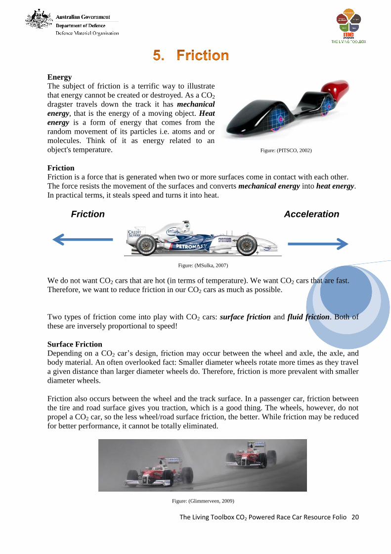
Friction
Friction is a force that is generated when two or more surfaces come in contact with each other.
The force resists the movement of the surfaces and converts mechanical energy into heat energy.
In practical terms, it steals speed and turns it into heat.
Friction Acceleration
Figure: (MSulka, 2007)
We do not want CO2 cars that are hot (in terms of temperature). We want CO2 cars that are fast.
Therefore, we want to reduce friction in our CO2 cars as much as possible.
Two types of friction come into play with CO2 cars: surface friction and fluid friction. Both of
these are inversely proportional to speed!
Surface Friction
Depending on a CO2 car’s design, friction may occur between the wheel and axle, the axle, and
body material. An often overlooked fact: Smaller diameter wheels rotate more times as they travel
a given distance than larger diameter wheels do. Therefore, friction is more prevalent with smaller
diameter wheels.
Friction also occurs between the wheel and the track surface. In a passenger car, friction between
the tire and road surface gives you traction, which is a good thing. The wheels, however, do not
propel a CO2 car, so the less wheel/road surface friction, the better. While friction may be reduced
for better performance, it cannot be totally eliminated.
Figure: (Glimmerveen, 2009)
The Living Toolbox CO2 Powered Race Car Resource Folio 21
Fluid Friction
As the CO2 car travels down the track, it moves through a
fluid. Most people do not think of air as a fluid, but it is.
While in motion, the CO2 car’s surface contacts air molecules.
Because there is relative motion between the car and air
molecules (the car is in motion while the air is stationary),
friction occurs.
Fluid friction contributes to drag, which is a resistance to the
forward motion of a body through a fluid (the air).
Figure: (PITSCO, 2002) Automotive engineers test their designs in wind tunnels. A wind tunnel simulates road airflow
conditions by moving a stream of air around a stationary car. The speed of the moving air can be
varied from very slow speeds to fast highway speeds.
Figure: (PITSCO, 2002)
Wind tunnels produce a laminar airflow. Laminar flow is a straight, layered flow of air without
turbulent air pockets known as eddies. It is desirable for a car in the tunnel to disturb the laminar
flow of air as little as possible. The presence of turbulence increases the aerodynamic drag, which
resists the car’s forward motion.
Figure: (PITSCO, 2002)
Surface friction and fluid friction also come into play as the inertia of the stationary car is
overcome. If the masses of two cars are equal, then the winner will likely be the car with the least
friction (PITSCO, 2002).
Wind Tunnels
A wind tunnel is a tool used in aerodynamic research
to study the effects of air moving past solid objects.
A wind tunnel consists of a closed tubular passage
with the object under test mounted in the middle. A
powerful fan system moves air past the object. CO2
racers can also test their cars in wind tunnel which
measures the frontal drag force.
Figure: (PITSCO, 2002)
The Living Toolbox CO2 Powered Race Car Resource Folio 22
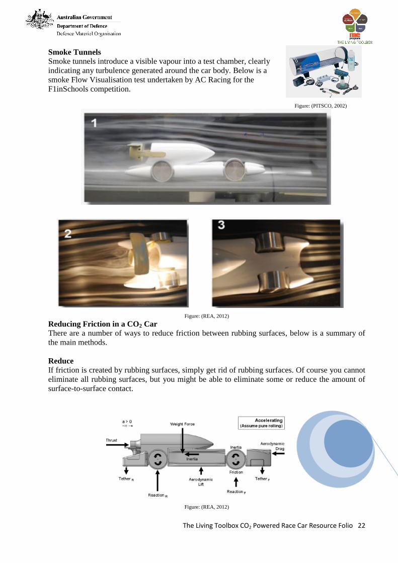
Smoke Tunnels
Smoke tunnels introduce a visible vapour into a test chamber, clearly
indicating any turbulence generated around the car body. Below is a
smoke Flow Visualisation test undertaken by AC Racing for the
F1inSchools competition.
Figure: (PITSCO, 2002)
Figure: (REA, 2012)
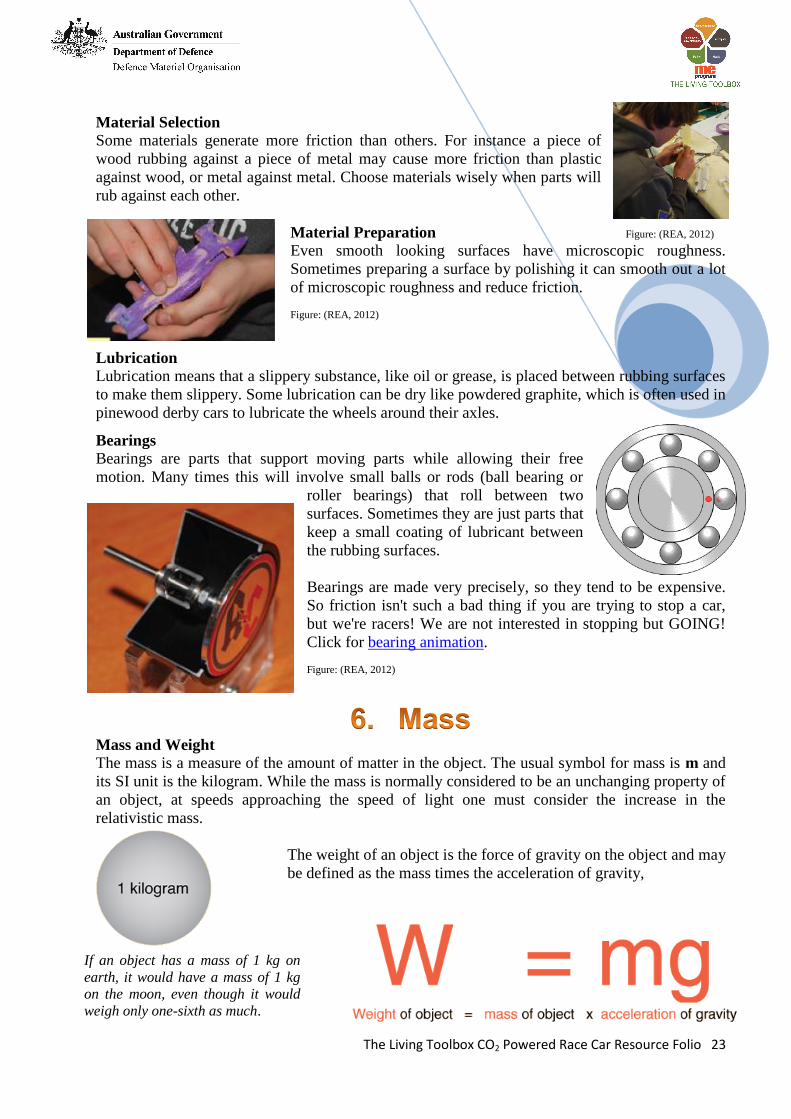
Reducing Friction in a CO2 Car
There are a number of ways to reduce friction between rubbing surfaces, below is a summary of
the main methods.
Reduce
If friction is created by rubbing surfaces, simply get rid of rubbing surfaces. Of course you cannot
eliminate all rubbing surfaces, but you might be able to eliminate some or reduce the amount of
surface-to-surface contact.
Figure: (REA, 2012)
The Living Toolbox CO2 Powered Race Car Resource Folio 23
Material Selection
Some materials generate more friction than others. For instance a piece of
wood rubbing against a piece of metal may cause more friction than plastic
against wood, or metal against metal. Choose materials wisely when parts will
rub against each other.
Material Preparation Figure: (REA, 2012)
Even smooth looking surfaces have microscopic roughness.
Sometimes preparing a surface by polishing it can smooth out a lot
of microscopic roughness and reduce friction.
Figure: (REA, 2012)
Lubrication
Lubrication means that a slippery substance, like oil or grease, is placed between rubbing surfaces
to make them slippery. Some lubrication can be dry like powdered graphite, which is often used in
pinewood derby cars to lubricate the wheels around their axles.
Bearings
Bearings are parts that support moving parts while allowing their free
motion. Many times this will involve small balls or rods (ball bearing or
roller bearings) that roll between two
surfaces. Sometimes they are just parts that
keep a small coating of lubricant between
the rubbing surfaces.
Bearings are made very precisely, so they tend to be expensive.
So friction isn't such a bad thing if you are trying to stop a car,
but we're racers! We are not interested in stopping but GOING!
Click for bearing animation.
Figure: (REA, 2012)
Mass and Weight
The mass is a measure of the amount of matter in the object. The usual symbol for mass is m and
its SI unit is the kilogram. While the mass is normally considered to be an unchanging property of
an object, at speeds approaching the speed of light one must consider the increase in the
relativistic mass.
The weight of an object is the force of gravity on the object and may
be defined as the mass times the acceleration of gravity,
If an object has a mass of 1 kg on
earth, it would have a mass of 1 kg
on the moon, even though it would
weigh only one-sixth as much.
The Living Toolbox CO2 Powered Race Car Resource Folio 24
What Do We Need to Know About Mass to Design Fast CO2 Car?
The first important thing to remember about mass when designing dragsters is that it is easier to
push a smaller mass than a larger one, remember the work on inertia.
All CO2 cars will be powered with an identical force. Basically you all will be using the same
engine a CO2 canister. You will gain an advantage over your competitors by concentrating on
streamlining, reducing friction and reducing mass. There is an equation that expresses how mass,
force and acceleration are related. The amount of Force is equal to the mass of an object times its
acceleration. Or...
F M a
Acceleration means how fast the CO2 car increases its speed. If your CO2 car increases its speed
by 10 meters per second every second, you would say that its acceleration is 10 meters per second
per second. You would write that as 10m/s2. If you want to see how mass affects your dragster's
acceleration we can change the equation to this:
mF
a
If the CO2 is propelled with a force of 20 Newtons (20N) and the dragster's mass is 2kg, then the
dragsters acceleration will be 10m/s2.
Fa
m
22010 /
2
Nm s
kg
If you cut more wood away from your CO2 car and reduced your mass to 1kg look at what would
happen to your acceleration.
22020 /
1
Nm s
kg
By cutting your mass in half, you double the acceleration
If less mass was always faster and always better, then why not tape a CO2 cartridge to a
toothpick? A toothpick is pretty tiny in diameter. What do you think would happen to it when it
hits the finish line, which is a block of wood?
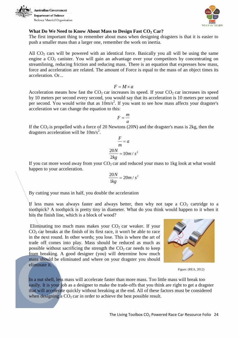
Eliminating too much mass makes your CO2 car weaker. If your
CO2 car breaks at the finish of its first race, it won't be able to race
in the next round. In other words; you lose. This is where the art of
trade off comes into play. Mass should be reduced as much as
possible without sacrificing the strength the CO2 car needs to keep
from breaking. A good designer (you) will determine how much
mass should be eliminated and where on your dragster you should
eliminate it. Figure: (REA, 2012)
In a nut shell, less mass will accelerate faster than more mass. Too little mass will break too
easily. It is your job as a designer to make the trade-offs that you think are right to get a dragster
that will accelerate quickly without breaking at the end. All of these factors must be considered
when designing a CO2 car in order to achieve the best possible result.
The Living Toolbox CO2 Powered Race Car Resource Folio 25
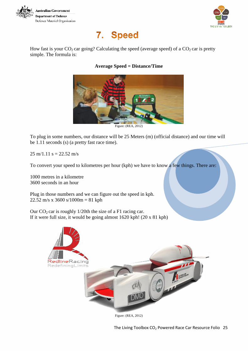
How fast is your CO2 car going? Calculating the speed (average speed) of a CO2 car is pretty
simple. The formula is:
Average Speed = Distance/Time
Figure: (REA, 2012)
To plug in some numbers, our distance will be 25 Meters (m) (official distance) and our time will
be 1.11 seconds (s) (a pretty fast race time).
25 m/1.11 s = 22.52 m/s
To convert your speed to kilometres per hour (kph) we have to know a few things. There are:
1000 metres in a kilometre
3600 seconds in an hour
Plug in those numbers and we can figure out the speed in kph.
22.52 m/s x 3600 s/1000m = 81 kph
Our CO2 car is roughly 1/20th the size of a F1 racing car.
If it were full size, it would be going almost 1620 kph! (20 x 81 kph)
Figure: (REA, 2012)
The Living Toolbox CO2 Powered Race Car Resource Folio 26
An excellent way to start any design work is to see what has already been produced. As a
starting point for your racer, research various CO2 cars using the F1inSchools website,
Google images, Flickr, etc. From the F1inSchools resources provided look at a number of
sample folios to gain a better appreciation of good CO2 car design.
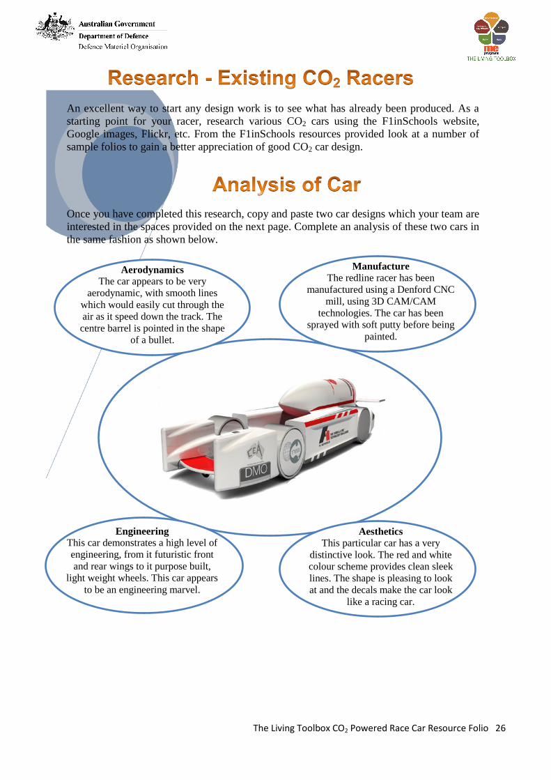
Once you have completed this research, copy and paste two car designs which your team are
interested in the spaces provided on the next page. Complete an analysis of these two cars in
the same fashion as shown below.
Aerodynamics
The car appears to be very
aerodynamic, with smooth lines
which would easily cut through the
air as it speed down the track. The
centre barrel is pointed in the shape
of a bullet.
Aesthetics
This particular car has a very
distinctive look. The red and white
colour scheme provides clean sleek
lines. The shape is pleasing to look
at and the decals make the car look
like a racing car.
Engineering
This car demonstrates a high level of
engineering, from it futuristic front
and rear wings to it purpose built,
light weight wheels. This car appears
to be an engineering marvel.
Manufacture
The redline racer has been
manufactured using a Denford CNC
mill, using 3D CAM/CAM
technologies. The car has been
sprayed with soft putty before being
painted.

The Living Toolbox CO2 Powered Race Car Resource Folio 27
Thumbnail Scaling
The object of this section is to learn how to resize or scale thumbnail sketches so that you can
attain a full size sketch of your CO2 car designs.
First though we need to learn a little about what scale is. Scale is a method that is used to resize
objects to make them larger or smaller both as drawings and in reality. For example when we
draw houses they are obviously too large to fit on a page so we can accurately resize them to
include all the details using scale.
When we use scale the great advantage is that all things that are to scale remain in proportion. In
the drawing below, as you can see the car on the right is much larger than the one on the left even
though they are the exact same drawing. However, the proportions are the same. The wheels are
as far apart on both drawings as an example.
A drawing of a real car cannot be of the same size as the car it represents. So, the measurements
are scaled down to make the drawing of a size that can be conveniently used by users such as car
manufacturer. A scale drawing of a car (or building) has the same shape as the real car (as above )
that it represents but a different size.
A ratio is used in scale drawings of maps, buildings and cars.
That is:
The scale of a drawing = Drawing Length : Actual Length
A scale is usually expressed in one of two ways:
using units as in 1 cm to 1 km
without explicitly mentioning units as in 1 : 100.
A scale of 1:100 means that the real distance is 100 times the length of 1 unit on the drawing
(Holden, 2011).
The Living Toolbox CO2 Powered Race Car Resource Folio 28
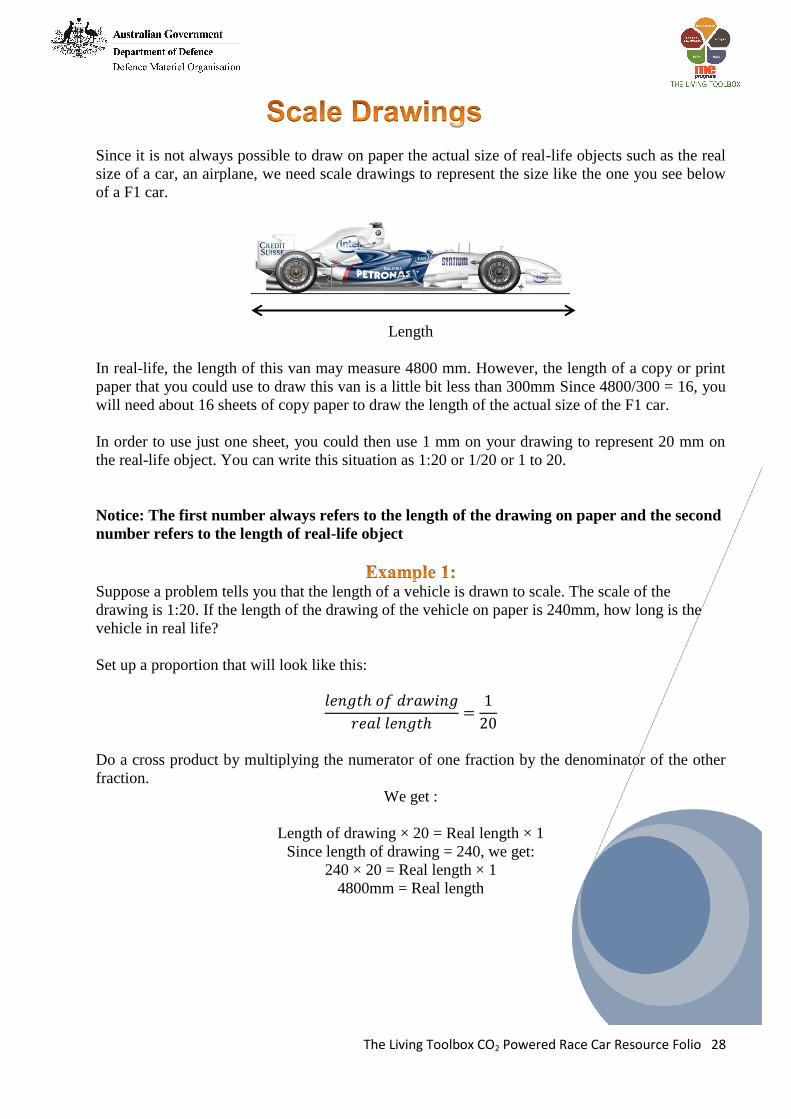
Since it is not always possible to draw on paper the actual size of real-life objects such as the real
size of a car, an airplane, we need scale drawings to represent the size like the one you see below
of a F1 car.
Length
In real-life, the length of this van may measure 4800 mm. However, the length of a copy or print
paper that you could use to draw this van is a little bit less than 300mm Since 4800/300 = 16, you
will need about 16 sheets of copy paper to draw the length of the actual size of the F1 car.
In order to use just one sheet, you could then use 1 mm on your drawing to represent 20 mm on
the real-life object. You can write this situation as 1:20 or 1/20 or 1 to 20.
Notice: The first number always refers to the length of the drawing on paper and the second
number refers to the length of real-life object
Suppose a problem tells you that the length of a vehicle is drawn to scale. The scale of the
drawing is 1:20. If the length of the drawing of the vehicle on paper is 240mm, how long is the
vehicle in real life?
Set up a proportion that will look like this:
Do a cross product by multiplying the numerator of one fraction by the denominator of the other
fraction.
We get :
Length of drawing × 20 = Real length × 1
Since length of drawing = 240, we get:
240 × 20 = Real length × 1
4800mm = Real length
The Living Toolbox CO2 Powered Race Car Resource Folio 29
The scale drawing of this tree is 1:500. If the height of the tree on paper is 50mm, what is the
height of the tree in real life?
Set up a proportion like this:
Do a cross product by multiplying the numerator of one fraction by the denominator of the other
fraction
We get :
Height of drawing × 500 = Real height × 1
Since height of drawing = 50, we get:
50 × 500 = Real length × 1
25000 mm ( 25metres ) = Real height
(Holden, 2011)
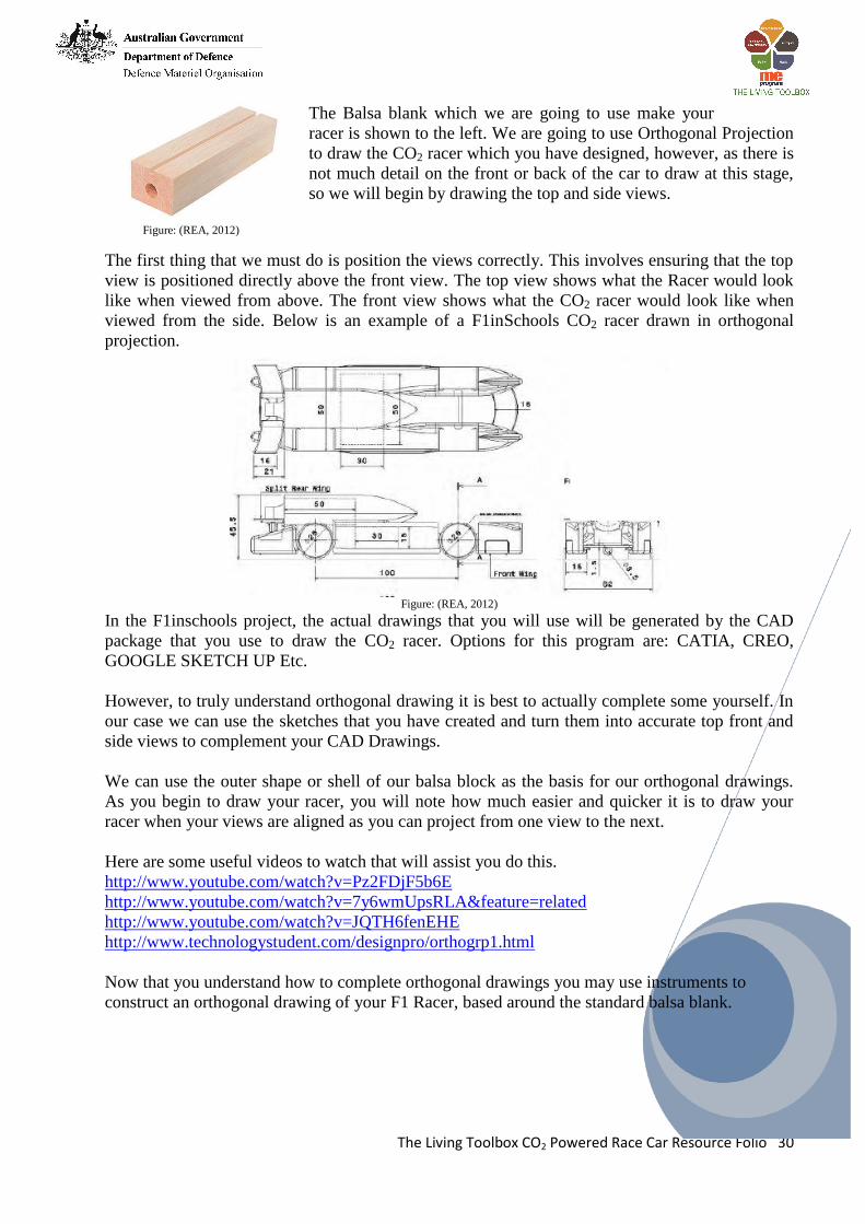
To be able to effectively draw your
CO2 racer, you first need to understand
that in drawing we use a type of
projection called orthogonal to draw
how things look from the top, front
and side.
To the right is an object drawn in
Orthogonal on the left and the same
object drawn in a 3D type projection
called Isometric on the right.
Orthogonal drawings are great for showing details and Isometric drawings are great for showing
the overall shape of an object.
The Living Toolbox CO2 Powered Race Car Resource Folio 30
The Balsa blank which we are going to use make your
racer is shown to the left. We are going to use Orthogonal Projection
to draw the CO2 racer which you have designed, however, as there is
not much detail on the front or back of the car to draw at this stage,
so we will begin by drawing the top and side views.
Figure: (REA, 2012)
The first thing that we must do is position the views correctly. This involves ensuring that the top
view is positioned directly above the front view. The top view shows what the Racer would look
like when viewed from above. The front view shows what the CO2 racer would look like when
viewed from the side. Below is an example of a F1inSchools CO2 racer drawn in orthogonal
projection.
Figure: (REA, 2012)
In the F1inschools project, the actual drawings that you will use will be generated by the CAD
package that you use to draw the CO2 racer. Options for this program are: CATIA, CREO,
GOOGLE SKETCH UP Etc.
However, to truly understand orthogonal drawing it is best to actually complete some yourself. In
our case we can use the sketches that you have created and turn them into accurate top front and
side views to complement your CAD Drawings.
We can use the outer shape or shell of our balsa block as the basis for our orthogonal drawings.
As you begin to draw your racer, you will note how much easier and quicker it is to draw your
racer when your views are aligned as you can project from one view to the next.
Here are some useful videos to watch that will assist you do this.
http://www.youtube.com/watch?v=Pz2FDjF5b6E
http://www.youtube.com/watch?v=7y6wmUpsRLA&feature=related
http://www.youtube.com/watch?v=JQTH6fenEHE
http://www.technologystudent.com/designpro/orthogrp1.html
Now that you understand how to complete orthogonal drawings you may use instruments to
construct an orthogonal drawing of your F1 Racer, based around the standard balsa blank.
The Living Toolbox CO2 Powered Race Car Resource Folio 31
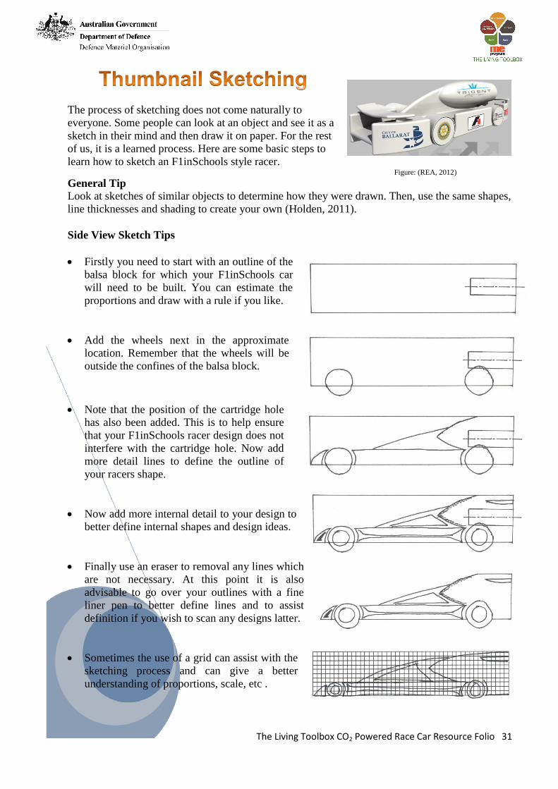
The process of sketching does not come naturally to
everyone. Some people can look at an object and see it as a
sketch in their mind and then draw it on paper. For the rest
of us, it is a learned process. Here are some basic steps to
learn how to sketch an F1inSchools style racer. Figure: (REA, 2012) General Tip
Look at sketches of similar objects to determine how they were drawn. Then, use the same shapes,
line thicknesses and shading to create your own (Holden, 2011).
Side View Sketch Tips
Firstly you need to start with an outline of the
balsa block for which your F1inSchools car
will need to be built. You can estimate the
proportions and draw with a rule if you like.
Add the wheels next in the approximate
location. Remember that the wheels will be
outside the confines of the balsa block.
Note that the position of the cartridge hole
has also been added. This is to help ensure
that your F1inSchools racer design does not
interfere with the cartridge hole. Now add
more detail lines to define the outline of
your racers shape.
Now add more internal detail to your design to
better define internal shapes and design ideas.
Finally use an eraser to removal any lines which
are not necessary. At this point it is also
advisable to go over your outlines with a fine
liner pen to better define lines and to assist
definition if you wish to scan any designs latter.
Sometimes the use of a grid can assist with the
sketching process and can give a better
understanding of proportions, scale, etc .
The Living Toolbox CO2 Powered Race Car Resource Folio 32
In order to continue with the design, testing and manufacturing of the CO2 racer, a 3D CAD
drawing of the racer needs to be completed.
The following drawings will be need to be completed.
1. Drawing of assembled car ready to be coded for manufacturing.
2. Orthogonal drawings of each side of car.
3. Detail drawings of features where required. Eg. Wheels
4. Completed car on a turntable, realistically rendered including shadows, just as the finished car
will look.
Some teams will require more drawings depending on their design and expertise.
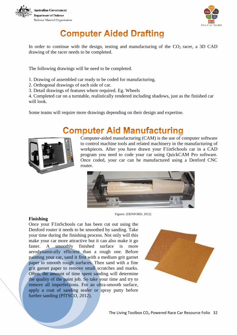
Computer-aided manufacturing (CAM) is the use of computer software
to control machine tools and related machinery in the manufacturing of
workpieces. After you have drawn your F1inSchools car in a CAD
program you need to code your car using QuickCAM Pro software.
Once coded, your car can be manufactured using a Denford CNC
router.
Figures: (DENFORD, 2012)
Finishing
Once your F1inSchools car has been cut out using the
Denford router it needs to be smoothed by sanding. Take
your time during the finishing process. Not only will this
make your car more attractive but it can also make it go
faster. A smoothly finished surface is more
aerodynamically efficient than a rough one. Before
painting your car, sand it first with a medium grit garnet
paper to smooth rough surfaces. Then sand with a fine
grit garnet paper to remove small scratches and marks.
Often, the amount of time spent sanding will determine
the quality of the paint job. So take your time and try to
remove all imperfections. For an ultra-smooth surface,
apply a coat of sanding sealer or spray putty before
further sanding (PITSCO, 2012).
The Living Toolbox CO2 Powered Race Car Resource Folio 33
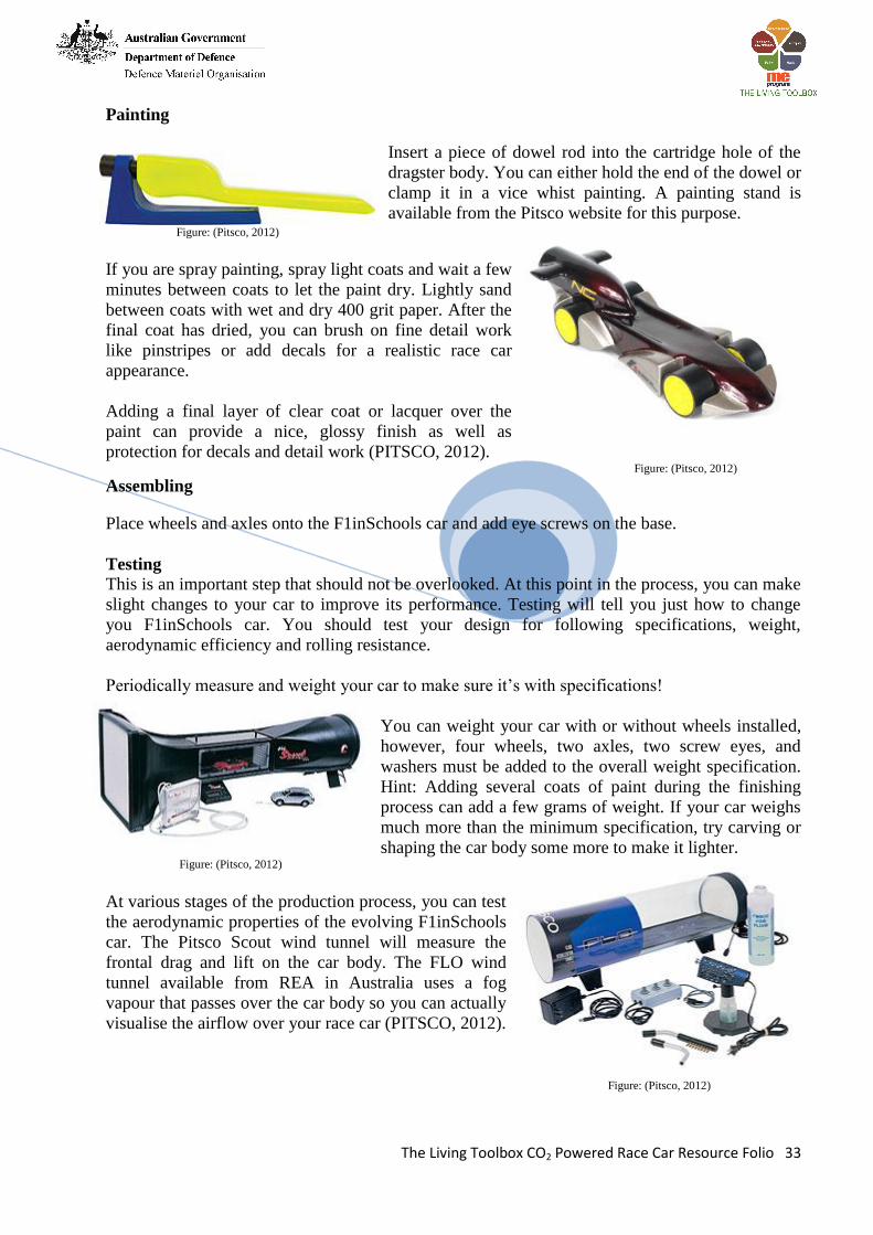
Painting
Insert a piece of dowel rod into the cartridge hole of the
dragster body. You can either hold the end of the dowel or
clamp it in a vice whist painting. A painting stand is
available from the Pitsco website for this purpose. Figure: (Pitsco, 2012)
If you are spray painting, spray light coats and wait a few
minutes between coats to let the paint dry. Lightly sand
between coats with wet and dry 400 grit paper. After the
final coat has dried, you can brush on fine detail work
like pinstripes or add decals for a realistic race car
appearance.
Adding a final layer of clear coat or lacquer over the
paint can provide a nice, glossy finish as well as
protection for decals and detail work (PITSCO, 2012). Figure: (Pitsco, 2012)
Assembling
Place wheels and axles onto the F1inSchools car and add eye screws on the base.
Testing
This is an important step that should not be overlooked. At this point in the process, you can make
slight changes to your car to improve its performance. Testing will tell you just how to change
you F1inSchools car. You should test your design for following specifications, weight,
aerodynamic efficiency and rolling resistance.
Periodically measure and weight your car to make sure it’s with specifications!
You can weight your car with or without wheels installed,
however, four wheels, two axles, two screw eyes, and
washers must be added to the overall weight specification.
Hint: Adding several coats of paint during the finishing
process can add a few grams of weight. If your car weighs
much more than the minimum specification, try carving or
shaping the car body some more to make it lighter. Figure: (Pitsco, 2012)
At various stages of the production process, you can test
the aerodynamic properties of the evolving F1inSchools
car. The Pitsco Scout wind tunnel will measure the
frontal drag and lift on the car body. The FLO wind
tunnel available from REA in Australia uses a fog
vapour that passes over the car body so you can actually
visualise the airflow over your race car (PITSCO, 2012).
Figure: (Pitsco, 2012)

The Living Toolbox CO2 Powered Race Car Resource Folio 34
Once you have completed this task you might like to consider forming a team and entering the
international F1inSchools technology challenge. Students not only learn about but also experience
engineering as they design, build, and race their CO2 powered cars. The main difference between
what you have done for this task and the completion is specifications and tolerances change each
year for the F1inSchools competition.
Specifications and Tolerances
Students designing and building CO2 race cars experience the same challenge faced by many
engineers: working with specifications and tolerances.
Specifications are a detailed set of requirements. Specifications can be measurements,
capabilities, or limitations on a CO2 cars, size, weight, or functionality. Often a designer is handed
a set of specifications before he or she begins a project. The CO2 cars must be able to do this, go
this fast, and be roughly this size. The challenge for the designer is to be creative and develop an
innovative, effective solution while working within the established parameters. In the F1inScools
innovation challenge a new set of specifications and rules are set it each year. For the F1inSchools
competition details of rules and specifications can be obtained from the REA web site
Tolerances are usually dictated to control the quality of a product. No two parts are ever made
exactly the same. There are minute differences (perhaps a few ten-thousandths of a millimetre) in
the measurements of two similar parts. Some variance in measurement is considered acceptable,
as long as it’s not too great. A tolerance is an acceptable variance from the specified measurement
(REA, 2012).
Using the race car project steps shown on the next page, as a guide and now that you are familiar
with some of the factors that influence racer design, you can begin to design your own racer based
around the principles that you have learnt. Firstly, the design process for a CO2 race car is linear,
that is, each step is followed in succession. However, as
there are a million different ways to build things, the
designer is quite often forced to consider other
components which relate to the area being designed.
Secondly, the design process demands some estimation
and compromise. Juggling is what it's all about. This is
where you want specifications ready to assist you in
putting the pieces together. In our case the rules and
regulations of the F1inSchools competition dictates the
parameters that our racers must be designed to meet
(REA, 2012). Figure: (REA, 2012)

The Living Toolbox CO2 Powered Race Car Resource Folio 35
The chart below illustrates the major steps in designing and eventually manufacturing a car. (See
explanations below) The design steps are discussed in more detail below.
RESEARCH
EXISTING F1
RACERS
F1 RULES AND
REGULATIONS
PRELIMINARY
DESIGN SKETCHES
DEVELOPMENT
OF PRELIMINARY
DESIGN
SKETCHES
FINAL DESIGN
on Paper and
then on CAD
Package
FINAL DESIGN
TESTING
( Computer Aided)
FINAL DESIGN
REFINEMENT
AND
COMPLETION
MANUFACTURING
OF RACER
PRELIMINARY
TESTING
COMPETITION RACER ANALYSIS
AND
REFINEMENT
The Living Toolbox CO2 Powered Race Car Resource Folio 36
1. Research of Existing F1 Racers is there to put a reality check into place before any work is
done. It is important to understand what existing F1 racers look like, their problems, prior to
spending time designing your racer.
Figures: (PITSCO, 2002)
2. F1 in Schools Rules and Regulations is the step where you must go out
research the rules and regulation that the completion runs by in order to
design a car which meets all of the criteria. Failure to do this at this point
may lead to extra work at later stages in redesigning.
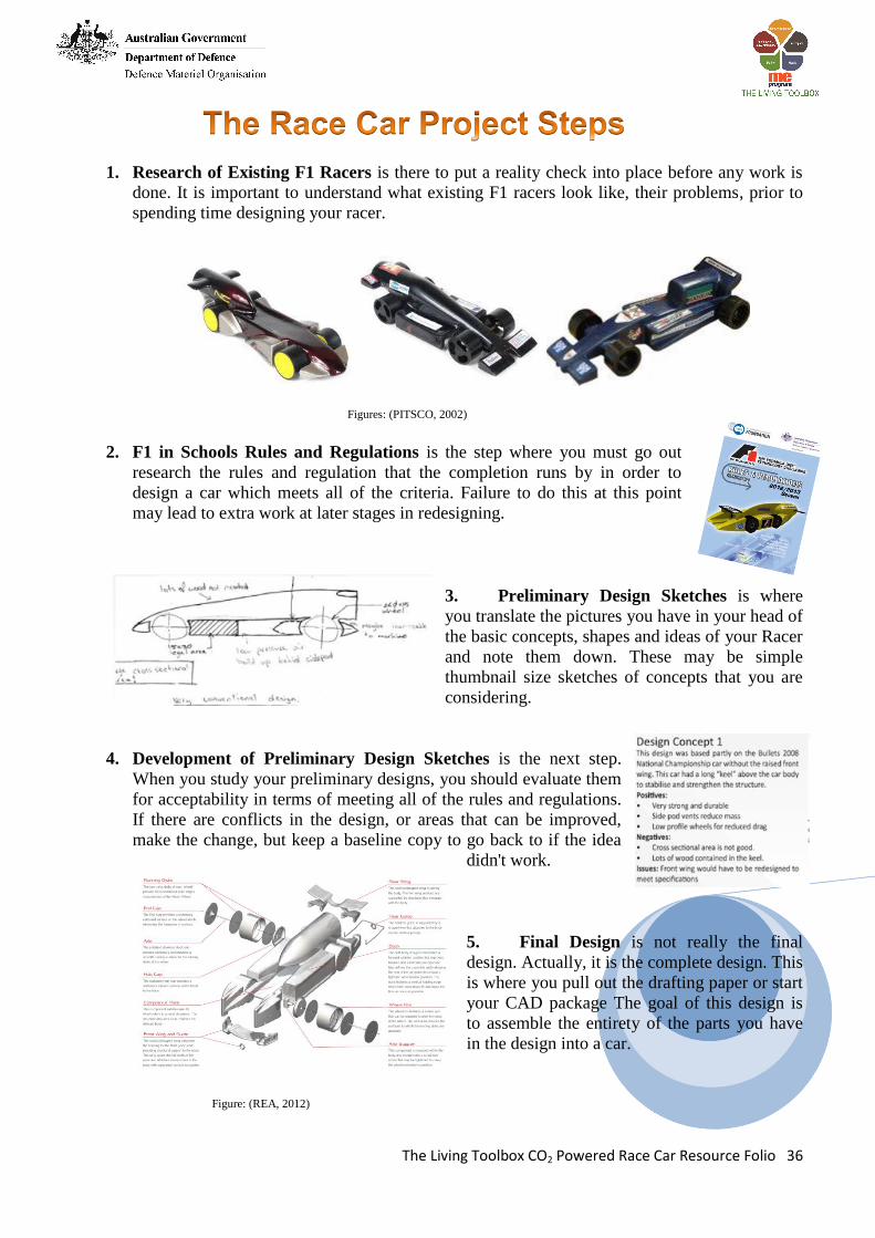
3. Preliminary Design Sketches is where
you translate the pictures you have in your head of
the basic concepts, shapes and ideas of your Racer
and note them down. These may be simple
thumbnail size sketches of concepts that you are
considering.
4. Development of Preliminary Design Sketches is the next step.
When you study your preliminary designs, you should evaluate them
for acceptability in terms of meeting all of the rules and regulations.
If there are conflicts in the design, or areas that can be improved,
make the change, but keep a baseline copy to go back to if the idea
didn't work.
5. Final Design is not really the final
design. Actually, it is the complete design. This
is where you pull out the drafting paper or start
your CAD package The goal of this design is
to assemble the entirety of the parts you have
in the design into a car.
Figure: (REA, 2012)
The Living Toolbox CO2 Powered Race Car Resource Folio 37
6. Final Design Testing can be done if you have the right software. These tools consist of Finite
Element Analysis and Fluid Dynamics simulations to test aerodynamics.
7. Final Design Refinement and Completion will
consist of small changes that will have become
apparent once the racer has been tested in the
virtual programs. If it's not clear, then you need to
revisit your final design stage. More often than
not, this will mean going back to research some
more to find solutions to problems or
shortcomings. Figure: (REA, 2012)
8. Manufacturing of the Racer is the point at
which the design of the racer which has been developed
is converted to a computer code which then allows the
Computer Aided Manufacturing System to read the
design and actually machine the racer.
Figure: (REA, 2012)
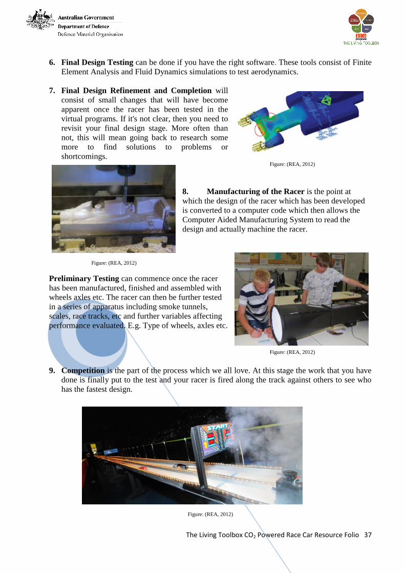
Preliminary Testing can commence once the racer
has been manufactured, finished and assembled with
wheels axles etc. The racer can then be further tested
in a series of apparatus including smoke tunnels,
scales, race tracks, etc and further variables affecting
performance evaluated. E.g. Type of wheels, axles etc.
Figure: (REA, 2012)
9. Competition is the part of the process which we all love. At this stage the work that you have
done is finally put to the test and your racer is fired along the track against others to see who
has the fastest design.
Figure: (REA, 2012)
The Living Toolbox CO2 Powered Race Car Resource Folio 38
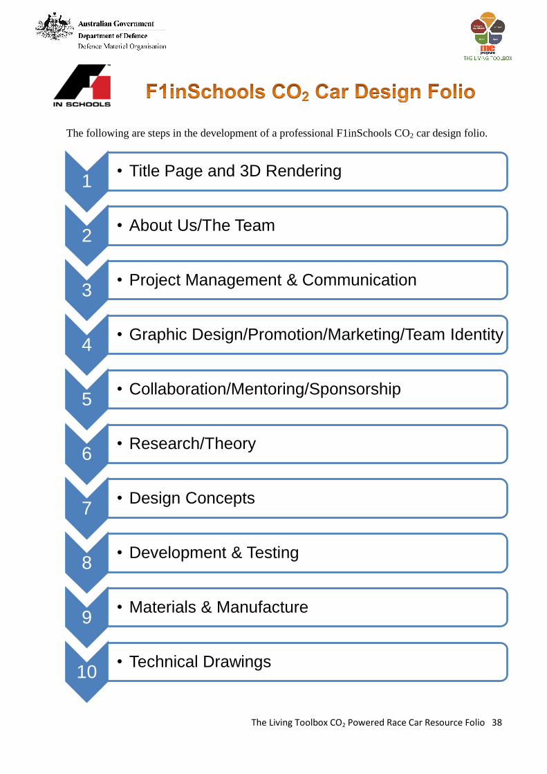
The following are steps in the development of a professional F1inSchools CO2 car design folio.
1 • Title Page and 3D Rendering
2 • About Us/The Team
3 • Project Management & Communication
4 • Graphic Design/Promotion/Marketing/Team Identity
5 • Collaboration/Mentoring/Sponsorship
6 • Research/Theory
7 • Design Concepts
8 • Development & Testing
9 • Materials & Manufacture
10 • Technical Drawings

The Living Toolbox CO2 Powered Race Car Resource Folio 39
[1] REA (2012). "Re-Engineering Australia Foundation." <http://rea.org.au/>. [2] LAVC (2012). "STEM." <http://www.lavc.edu/stem/summerBridge.html>. [3] PITSCO (2002). "The Science of Speed." <http://www.science-of-speed.com/default.asp>. [4] Creationtips (2009). "Robert Boyle Biography." <http://www.creationtips.com/boyle.html>. [5] Benson, T. (2007). "Animated Boyle's Law." <http://www.grc.nasa.gov/WWW/K-12/airplane/aboyle.html>. [6] uoregon (2012). "Chapter 14: Gases and Plasmas." <http://hendrix2.uoregon.edu/~imamura/102/section2/chapter14.html>. [7] old-picture.com (2006-2008). "Wright Brothers Airplane." <http://www.old-picture.com/wright-brothers/Wright-Brothers-Airplane-001.htm>. [8] Cislunar (1997-1998). "The Wind Tunnel." <http://www.fi.edu/wright/again/wings.avkids.com/wings.avkids.com/Tennis/Project/wind-01.html>. [9] OTEN (2002). "Aeronautical Engineering " Distance Education, OTEN, Dubbo. [10] Cetin (2005). "Zodiac CH 640 Design and Construction." <http://zamandayolculuk.com/cetinbal/HTMLdosya2/UcakYapisalParcalari.htm>. (7/8/2012, 2012). [11] Illusionist (2011). "Introduction to Aeroplane." <http://engg-learning.blogspot.com.au/2011/03/introduction-to-aeroplane-airplane-is.html>. [12] Collier, J. (1904). "Osborne Reynolds Scientist, Engineer and Pioneer." <http://johnbyrne.fireflyinternet.co.uk/Osborne%20Reynolds/oreyna.htm>. [13] Barker (2012). "Slow is Faster." <http://blog.nialbarker.com/252/slow_is_faster>. [14] DENFORD (2012). "DENFORD." <http://website.denford.ltd.uk/>. [15] Ryan, E., . Ryan, M,. Withero, D,. Bresnan,. D. (2012). "Team Blink." <http://blinkf1.blogspot.com.au/2010/08/home.html>. [16] Flightlearnings (2012). "Lift and Basic Aerodynamics." <http://www.flightlearnings.com/2011/03/14/lift-and-basic-aerodynamics/>. (7/8/2012, 2012). [17] Adamone (2012). "Aerodynamics." <http://adamone.rchomepage.com/index2.htm>. [18] Scott, J. (2005). "Golf Ball Dimples & Drag." <http://www.aerospaceweb.org/question/aerodynamics/q0215.shtml>. (7/8/2012, 2012). [19] Cortana (2006). "Description of Drag." <http://www.cortana.com/Drag_Description.htm>. [20] Edmont (2009). "Boat sailing the Lyse fjord in Norway." <http://en.wikipedia.org/wiki/File:Fjord.surface.wave.boat.jpeg>. [21] NASA (1990). "Wake Vortex Study." <http://en.wikipedia.org/wiki/File:Airplane_vortex_edit.jpg>. [22] Aquaphoenix (2012). "Segway Human Transporter in Simplified Mechanics." <http://www.aquaphoenix.com/lecture/matlab5/page2.html>. (19/08/2012, 2012). [23] Magda, M. (2006). [24] MSulka (2007). "Technical Feature: In Depth of Preparing a Formula One Car for Monza." PaddockTalk, <http://www.paddocktalk.com/news/html/story-65408.html>. [25] Holden, B. (2011). The Engineered Dragster: Design Basics, Pitsco. [26] Glimmerveen, J. (2009). "Formula One Suspension Set-Up for the Rain." Auto Racing Suite101, <http://suite101.com/article/formula-one-suspension-setup-for-the-rain-a111694>. [27] Holden, B. (2011). The Engineered Dragster: Sketching, Drafting, and Prototyping, Pitsco. [28] PITSCO (2012). The Race Car Book, Pittsburg. [29] Pitsco (2012). "Pitsco Education Store." <http://www.pitsco.com/store/>. (19/08/2012, 2012).