Embed Size (px)
Citation preview
DDDDeeeessssiiiiggggnnnn GGGGuuuuiiiiddddeeeelllliiiinnnneeeessssfor pedestrian accessibility
FOR ACCESSIBLE PEDESTRIAN ENVIRONMENTS
(Including: $$$$ Streetscapes$$$$ Accessible Bus Stops$$$$ Bus Transfer Stations)
Alberta Transportation and Utilities
March 1996
Reformatted for Internet July 2000
J:\DATA\URBAN\MANUALS\ACCESS96GDE for Internet
FOREWORD AND ACKNOWLEDGEMENTS
The need to provide access for all persons to public environments such as sidewalks,plazas, public transit and other services has created the necessity to develop thiscomprehensive "Design Guideline for Accessible Pedestrian Environments". To providesome degree of consistency, design professionals, municipal public works departments,government agencies, and developers will be encouraged to use these guidelines forprojects throughout the Province. These guidelines are combined with an existingdocument "Design Guidelines for Accessible Bus Stops" which was created to fill a needto accommodate persons using mobility aids when accessing low-floor transit buses. Also addressed is bus transfer station accessibility. Under the auspices of the Minister ofTransportation and Utilities' Advisory Committee on Barrier-Free Transportation, asubcommittee, composed of the following individuals, was formed to review and developguidelines for accessible pedestrian environments.
Alberta Transportation and Utilities
Bob Rebus (Chair) Grants & Administration SectionCatherine Taylor (Secretary) Policy Development BranchBill Kenny Roadway Engineering Branch
Minister's Advisory Committee on Barrier-Free Transportation
Diane Earl Premier's CouncilChris Bellchamber Council on AgingWendy Edey Representing persons with vision impairments
These guidelines have been reviewed by many consumer groups and designprofessionals in Alberta and endorsed by the Minister's Advisory Committee on Barrier-Free Transportation. It is intended that these guidelines will provide guidance to citypublic works managers and transit planners, design professionals and developers.
The subcommittee would also like to thank the members of the Minister's AdvisoryCommittee, the many consumer groups, design professionals and transit systemsrepresentatives who have reviewed the guidelines and provided their valuable input.
- i -
We also wish to acknowledge the following individuals who were involved withthe original "Design Guidelines For Accessible Bus Stops" which wascompleted September, 1994 and now forms a part of this consolidatedaccessibility guideline.
Alberta Transportation and Utilities
Ken Dmytryshyn (Chair) Grants and Administration (UrbanTransportation Branch)
Diane Earl (Secretary) Policy Development BranchVincent Wu (Project Coordinator) Grants and Administration (Urban
Transportation Branch)Bill Kenny Roadway Engineering Branch
Alberta Transit Systems
Colleen Connelly Calgary TransitDez Liggett St. Albert TransitSteve Ma St. Albert TransitDoug Langille Edmonton Transit
Minister's Advisory Committee on Barrier-Free Transportation
Mark Iantkow Parks CanadaBev Allison Committee Member, Calgary
Any questions or comments on these guidelines may be forwarded to theGrants and Administration Section of the Planning and Programming Branch,Alberta Transportation and Utilities, Fourth Floor, Twin Atria Building, 4999 - 98Avenue, Edmonton, Alberta T6B 2X3.
- ii -
GUIDELINES FOR DESIGN OF SAFEACCESSIBLE PEDESTRIAN ENVIRONMENTS
TABLE OF CONTENTS
PART A - STREETSCAPESPage
1.0 Introduction..............................................................................................................12.0 Principles of Good Design.......................................................................................13.0 Some Barriers to Travel ..........................................................................................34.0 Design Solutions......................................................................................................4
PART B - ACCESSIBLE BUS STOPS AND BUS TRANSFER STATIONS
5.0 Introduction..............................................................................................................76.0 Background .............................................................................................................77.0 Principles of Mobility................................................................................................88.0 Principles of Effective Orientation, Wayfinding and Warning .................................89.0 Design Envelope ...................................................................................................1010.0 Elements of an Accessible Environment...............................................................10
10.1 Walkways ...............................................................................................1110.2 Curb Ramps ...........................................................................................1210.3 Bus Stop Location ..................................................................................1210.4 Bus Stops ...............................................................................................1310.5 Shelters ..................................................................................................1510.6 Seating ...................................................................................................1610.7 Rural Bus Stops......................................................................................1610.8 Signing....................................................................................................1710.9 Tactile Warning Strips ............................................................................18
11.0 Bus Transfer Stations............................................................................................1911.1 Introduction.............................................................................................1911.2 Building and Shelter Features................................................................1911.3 Curb Ramps ...........................................................................................2011.4 Streetscope Features ............................................................................2011.5 Street Lights and Bus Stop Signs ..........................................................20
12.0 Summary ...............................................................................................................21
- iii -
LIST OF EXHIBITS
Figure C-7.2.5a. Design Envelope to Accommodate Wheelchair Users
Figure C-7.2.5b. Minimum Requirements for Bus Stops Accessible toWheelchair Users
Figure C-7.2.6.2. Sidewalk Widths and Curb Ramps
Figure C-7.2.6.4a. Transit Stop - Built-Up, Monolithic Sidewalk
Figure C-7.2.6.4b. Transit Stop - Built-Up, Boulevard
Figure C-7.2.6.4c. Transit Stop - Suburban, Monolithic Sidewalk
Figure C-7.2.6.4d. Transit Stop - Suburban, Boulevard
Figure C-7.2.6.4e. Transit Stop - Suburban, Wide Boulevard
Figure C-7.2.6.4f. Transit Stop - Rural Situation
Figure C-7.3.1a. Transit Transit Station (with building)
Figure C-7.3.1b. Transit Transit Station (without building)
APPENDIX 1: ALBERTA TRANSPORTATION AND UTILITIESCURB RAMP AND SIDEWALK STANDARDS
APPENDIX II: LIST OF RESOURCE PUBLICATIONS
- iv -
GUIDELINES FOR ACCESSIBLEPEDESTRIAN ENVIRONMENTS
PART A
STREETSCAPES
GUIDELINES FOR DESIGN OFSAFE ACCESSIBLE PEDESTRIAN ENVIRONMENTS
PART A - STREETSCAPES
1.0 Introduction
Pedestrian environments which are designed to be used by the general public, including those withdisabilities, should be accessible to all persons, as well as being safe, functional and attractive. Thepurpose of these guidelines is to bring together the principles of good design as well as to highlightsome of the commonly experienced barriers in the pedestrian environment and to illustrate somedesign solutions.
2.0 Principles of Good Design
Pedestrian environments in public places, either publicly or privately owned, should be designed toallow safe and convenient access by all pedestrian traffic. Although the majority of pedestriantraffic is ambulatory, a significant and growing number of pedestrians have somewhat restrictedmobility due to disability or age. This group includes persons using walkers, scooters, wheelchairs(both manual and electric), people with impaired vision or hearing and some seniors. An additionalgroup may have limited mobility temporarily due to the need to bring along a baby carriage or otherwheeled device on their trips.
To ensure that the design of pedestrian environments accommodates the greatest possible numberof people, it is desirable to adhere to the following:
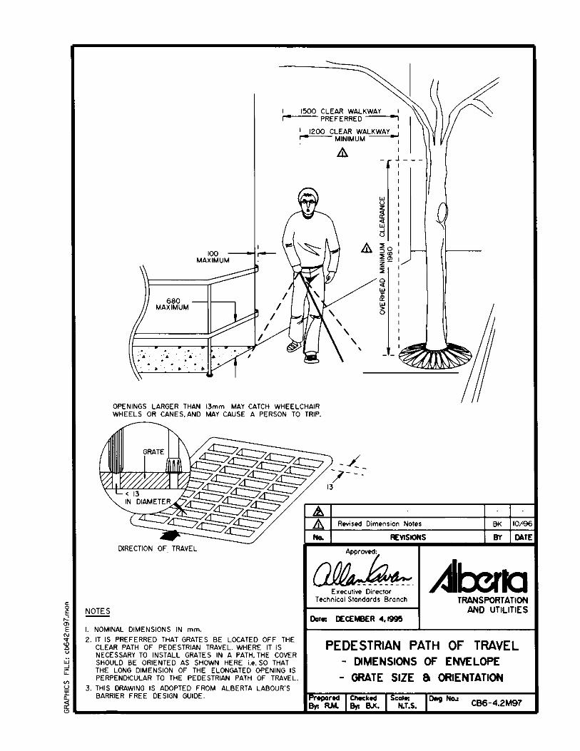
1. Allow a clear path of travel, free of obstructions to a minimum height of 1980 mm.Examples of obstructions are directional signs, tree branches, guy wires and streetfurniture. Handrails projecting up to 100 mm into the clear path of travel are permitted. Seedrawing CB6-4.2M97.
2. Provide a firm, even, non-slip, glare-free surface (for example: broom concrete finish). Anelevation change of 13 mm or more is considered to be a trip hazard and therefore shouldnot be permitted in the clear path of travel.
1
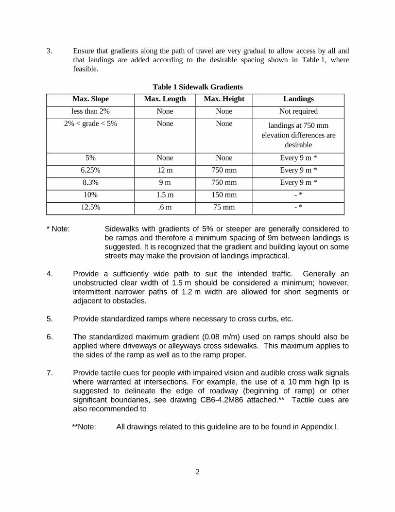
3. Ensure that gradients along the path of travel are very gradual to allow access by all andthat landings are added according to the desirable spacing shown in Table 1, wherefeasible.
Table 1 Sidewalk GradientsMax. Slope Max. Length Max. Height Landingsless than 2% None None Not required
2% < grade < 5% None None landings at 750 mmelevation differences are
desirable
5% None None Every 9 m *6.25% 12 m 750 mm Every 9 m *8.3% 9 m 750 mm Every 9 m *10% 1.5 m 150 mm - *
12.5% .6 m 75 mm - *
* Note: Sidewalks with gradients of 5% or steeper are generally considered tobe ramps and therefore a minimum spacing of 9m between landings issuggested. It is recognized that the gradient and building layout on somestreets may make the provision of landings impractical.
4. Provide a sufficiently wide path to suit the intended traffic. Generally anunobstructed clear width of 1.5 m should be considered a minimum; however,intermittent narrower paths of 1.2 m width are allowed for short segments oradjacent to obstacles.
5. Provide standardized ramps where necessary to cross curbs, etc.
6. The standardized maximum gradient (0.08 m/m) used on ramps should also beapplied where driveways or alleyways cross sidewalks. This maximum applies tothe sides of the ramp as well as to the ramp proper.
7. Provide tactile cues for people with impaired vision and audible cross walk signalswhere warranted at intersections. For example, the use of a 10 mm high lip issuggested to delineate the edge of roadway (beginning of ramp) or othersignificant boundaries, see drawing CB6-4.2M86 attached.** Tactile cues arealso recommended to
**Note: All drawings related to this guideline are to be found in Appendix I.
2
delineate the edge of hazard in pedestrian areas, for example edge of platform atrail station or top of stairs, etc. For additional information on Audible TrafficSignals, designers are referred to the Uniform Traffic Control Devices for Canadamanual, published by the Transportation Association of Canada.
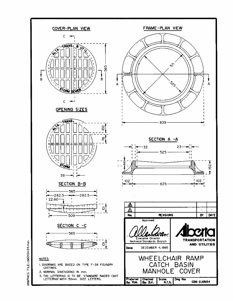
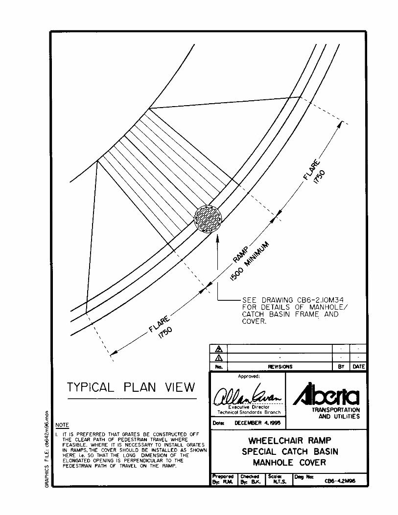
8. Ensure that drainage grates on the covers of catch basins or manholes arelocated off the clear path of travel where possible, i.e. not on curb ramps forexample. Where it is not feasible to relocate a catch basin off a ramp, for exampledue to excessive cost on a retrofit project, the second choice is to offset the rampprovided that the ramp will still give direct access to the crosswalk. The thirdchoice is to have the grate installed in the ramp however in this case the covershould be installed as shown on drawing CB6-4.2M96 i.e. so that the longdimension of the elongated opening is perpendicular to the pedestrian path oftravel on the ramp.
9. Grates for non-drainage structures for example electrical vaults or accesshatches, etc., should be located off the clear path of travel where possible. Wheregrates are necessary, they should have no opening that will permit the passage ofa sphere more than 13 mm diameter. Drawing CB6-4.2M97 shows the maximumrecommended opening size and orientation for non-drainage grates located inpedestrian areas. If the gratings have elongated openings, they should be placedso that the long dimension is perpendicular to the direction of travel.
3.0 Some Barriers to Travel
Although most pedestrian environments in Alberta that have been designed and built inrecent years are generally barrier-free, there are some construction and operationalpractices that present a barrier to the public at large and can have a much morerestrictive impact on people with transportation disabilities.
One set of obstacles can generally be referred to as street furniture. This includes lightpoles, fire hydrants, traffic signals, signs, bus benches, mail boxes, newspaper vendingmachines, sandwich boards, tables, bike racks, waste receptacles, telephone booths,bollards, trees, etc. These items are frequently needed or desired on streets, howevertheir placement should be carefully planned to ensure that they do not become a hazardfor people with impaired vision or an obstacle for wheelchair users or other pedestrians.
3
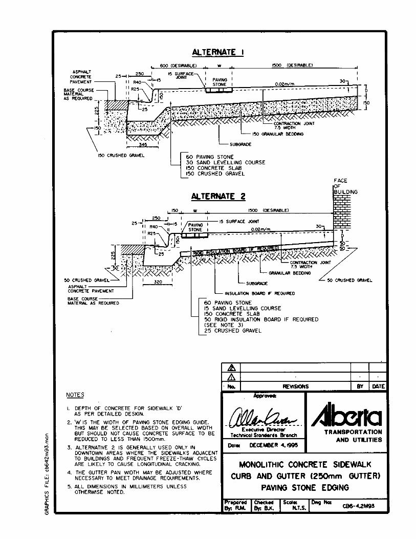
A second area of concern, especially for older pedestrians and wheelchair users is theuse of paving stones or bricks in pedestrian areas. The main difficulty with paving stonesis the uneven surface that can result due to differential settlement that generally occurswithin a few years of construction. Some paving stones have rounded edges on thesurface which creates a wider and deeper joint. The uneven surfaces and joints cancause pedestrians to trip, will give wheelchair users a rough ride and could contribute topersons falling from their wheelchairs. Where paving stones are used in an indoor setting,although frost heaving and differential settlement may be eliminated, the stone surfacestill provides a less than ideal riding surface for people using wheelchairs.
Based on the above, it is preferred that an even concrete surface be provided for themain path of travel through pedestrian areas. Ideally, paving stones should be used asborders only. Where a designer chooses to use a paving stone edger on a sidewalk, theoutside edge (adjacent to curb) is generally preferred. This provides a good tactile cue forpeople with impaired vision while also ensuring that the main path of pedestrian travel isseparated from vehicular traffic. In general, a safer and more functional pedestrianenvironment would result if the clear path of travel was given top priority in all layouts i.e.with decorative finishes, paving stone tree surrounds and other street furniture not beingpermitted to encroach on the path of travel.
4.0 Design Solutions
1. Ensure street furniture does not encroach on the clear path of travel inpedestrian areas.
In the case of lower volume residential or light industrial sidewalks where amonolithic curb, gutter and sidewalk cross-section has been selected, it ispreferred that all street furniture be placed on the private property side of thesidewalk i.e. away from the roadway, so as not to encroach on the clear path oftravel.
Where additional right-of-way is available, a boulevard between roadway andsidewalk is very desirable aesthetically, provides greater safety for pedestriansand allows street furniture to be placed off the pedestrian walking surface.
4
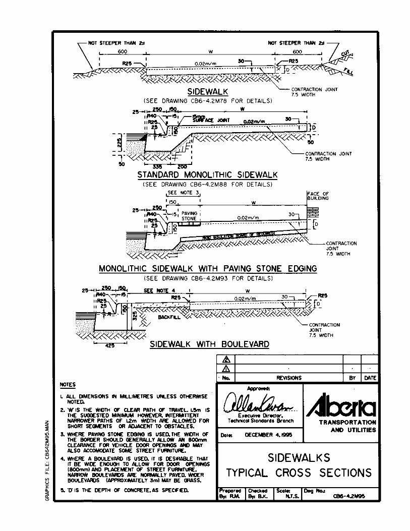
Where wider sidewalks are required, for example in commercial or businessareas or in the vicinity of educational or health care facilities, the sidewalkcross-section should generally be designed to accommodate street furniturewithout encroaching on the clear path of travel and while still providing a minimum800 mm offset from the curb to allow for vehicle door-openings. Where buildingsare constructed adjacent to sidewalks, it is best to place street furniture on thecurb side of the walkway thus providing a greater offset between the pedestrianclear path of travel and the vehicular traffic. The absence of obstructions along theface of buildings is desirable.
On major arterial roads, where higher speeds and higher traffic volumes areexpected, a 3 m offset between curb and sidewalk is desirable. A grass surfacemay be used to provide a contrasting colour and texture for the boulevard.
Drawing CB6 4.2M95 (attached) shows the typical cross-sections for thesidewalks described here.
2. If paving stones are required on a project, they should not be placed acrossthe main path of travel where they would be a barrier or possible hazard tosome pedestrians.
In addition to the above, measures should be taken to ensure that the effects offrost heave and/or differential settlement of paving stones are minimized. Experience has shown that the best way to ensure the integrity of a surface is tobuild a strong base. The major cities in Alberta have used either lean concrete orsoil cement for this purpose. A levelling course of sand is generally used on top ofthe base and the paving stones are placed on the sand. If the back of thewalkway is within 3.0 m of a building, a 50 mm layer of rigid insulation is typicallyplaced under the base to reduce frost penetration into the subgrade. A 50 mmlayer of crushed gravel may also be used below the insulation. The attacheddrawing, CB6 4.2M93, shows a typical structure which should provide a safe,smooth partially paved sidewalk.
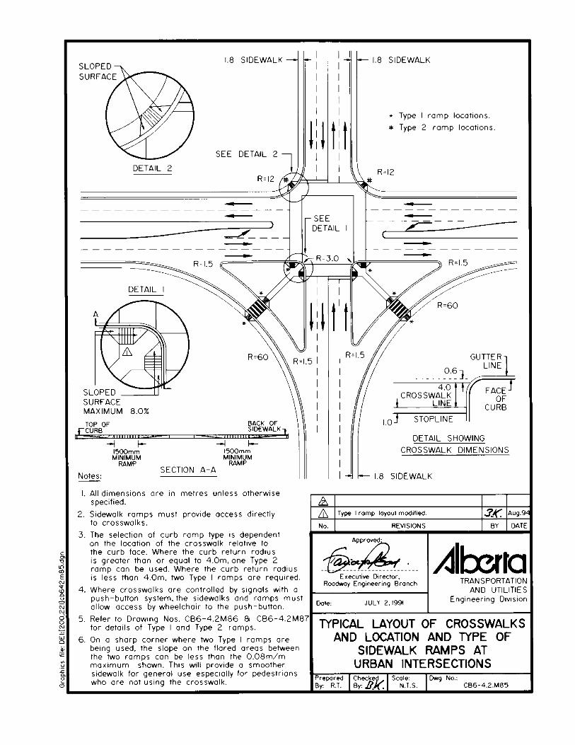
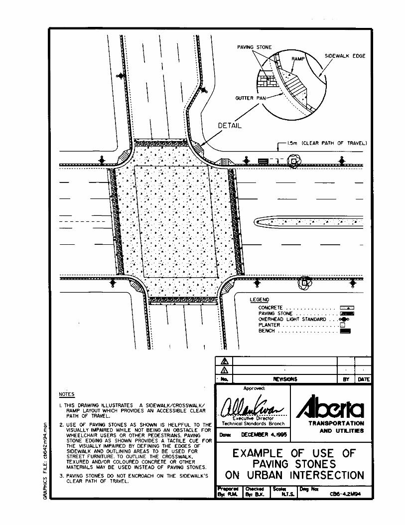
CB6 4.2M94 is a plan view of a typical urban intersection where paving stones have beenused to delineate the edge of sidewalk and crosswalk while not obstructing the clear pathof travel. Drawings CB6-4.2M85, 86, 87 and 91 are also included to show the typicallayout and construction details for ramps where urban sidewalks meet crosswalks.Drawing CB6-2.10M34 shows the details of a special catch basin/manhole frame andcover that is suitable for use on a curb ramp.
5
GUIDELINES FOR ACCESSIBLEPEDESTRIAN ENVIRONMENTS
PART B
ACCESSIBLE BUS STOPS ANDBUS TRANSFER STATIONS
GUIDELINES FOR DESIGN OFSAFE ACCESSIBLE PEDESTRIAN ENVIRONMENTS
PART B - ACCESSIBLE BUS STOPS AND BUS TRANSFER STATIONS
5.0 Introduction
As early as 1992, Alberta municipalities had begun to make their conventional transit systems moreaccessible for persons with disabilities and seniors. The customary transit bus is being replaced byan accessible, full-size, low-floor bus as fleet replacement becomes necessary. By eliminating theneed to climb stairs within buses, seniors find boarding much easier and ambulatory passengers areable to board quicker. The use of a ramp on the bus enables persons using wheelchairs or othermobility aids to easily access the vehicle and ride the public transit system.
As part of the plan to implement accessible buses into transit routes, transit managementacknowledge the need to address the matter of access in the pedestrian environment, specifically atbus stops. Transit planners are enlisting the assistance of consumers to review the current status ofthe pedestrian environment and provide feedback on how bus stops can be made more accessible. Both consumers and transit management recognize that in order to ensure consistency across theprovince, it is essential that various guidelines be developed. The Alberta Chapter of the CanadianUrban Transit Association have also endorsed the need for provincial guidelines.
6.0 Background
The Alberta Committee to Review Design Guidelines, a subcommittee of the Minister ofTransportation and Utilities' Advisory Committee on Barrier-Free Transportation, examined areport developed by an Ontario Ministry of Transportation task force. This task force investigatedmethods to improve accessibility to conventional transit services and conducted extensiveexamination of existing literature. They identified key issues and design considerations which arefundamental to improving the accessibility and usability of bus stops.
In developing the Alberta guidelines, the Alberta Committee, comprised of consumers andrepresentatives from Alberta transit systems and Alberta Transportation and Utilities personnel,reviewed the design considerations for bus stops in the Ontario report and a similar document, theBC Transit Design Guidelines for Accessible Bus Stops, and in some instances modified thesedesigns to address conditions for Alberta transit systems.
The Alberta guidelines have been developed to assist Alberta transit systems as they move towardproviding accessible transit services through the implementation of community and low-floorbuses. The guidelines are uniform and flexible, and reference other standards such as the AlbertaBuilding Code and the curb ramp standards developed by Alberta Transportation and Utilities. These guidelines are not meant to be standards but rather to serve as design guidelines which can beinterpreted and adapted to specific situations in each municipality. Information contained withinthe guidelines can also be used for the design of boarding and alighting areas for other accessiblevehicles, including taxis, charter buses/vans, and in some instances, private vehicles.
6
7.0 Principles of Mobility
The basic principles of mobility in a pedestrian environment are:
$ Avoid level changes wherever possible.
$ Provide non-slip finishes, good grip, and sure footing to ensure surfaces are safe.
$ Provide opportunities for seating adjacent to travel routes.
$ Plan exterior elements to minimize obstacles and eliminate travel hazards by ensuringthere is adequate overhead clearance and no protrusions into the path of travel. Newspaperboxes and other street furniture should be placed close to the edge of the travel path but outof the main flow of pedestrian traffic.
$ Avoid glare from surfaces in all lighting conditions.
8.0 Principles of Effective Orientation, Wayfinding and Warning
The basic principles of orientation are:
$ Provide consistency and uniformity of design elements and layout.
$ Simplify orientation by using right angles for design elements and layout.
$ Provide visual as well as tactile cues and landmarks within designs (examples: sidewalkswith grass shoulders or borders; street furnishings such as benches, trash containers,planters located adjacent to but not within path of travel; high contrasts on shelter doorframes, benches and planters).
$ Walkways, hazards and waiting areas should be well illuminated for orientation andsecurity purposes.
The basic principles of wayfinding are:
$ Provide logical, unbroken path of travel from sidewalk to bus boarding area.
$ Paths of travel may be easily identified by proper placement of street furniture, which, forexample, can be placed to highlight location of sidewalk or ends of bus zone.
$ Use colour contrast, sound, light and shade to accentuate paths of travel between shelter,sidewalk and bus boarding area.
$ In rare circumstances, tactile wayfinding tiles may be used to accentuate paths of travel ifpedestrian pathway is broken or wayfinding is complicated (note, however, suchwayfinding tiles must be consistent in design and well differentiated from tactile warningstrips). Wayfinding tiles are usually of gentle and corduroy textures, whereas warning tilesare typically of raised dot textures.
7
The basic principles of warning are:
$ A bus stop with good ergonomics and effective wayfinding/colour contrast or tactile cueswill also be beneficial for safety and warning purposes.
$ Placement of street furniture such as benches, newspaper stands and planters for creationof a barrier from hazards will assist in preventing mishaps.
$ Tactile indicators such as tactile warning tiles may be used in rare circumstances toaccentuate a large difference in elevation (note, however, such warning tiles must beconsistent in design and well differentiated from tactile wayfinding tiles).
9.0 Design Envelope
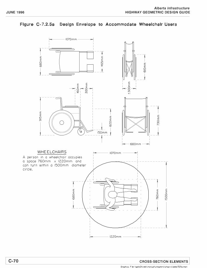
When developing a design standard or guideline, it is generally necessary to select a "design user"or "user envelope", as well as a "design vehicle" in this case the bus. In the case of accessible busstops and transit zones, a design envelope for the user has been selected to accommodate mostconventional wheelchairs and other mobility aides which could gain access to low-floor transitbuses. This is considered to an extension of the person using the mobility aid. This envelope hasthe following dimensions:
1.22 m (length) x 0.76 m (width).
Height of the design envelope is not considered to be a critical factor or constraint. Accessiblebuses or other vehicles to be used to transport wheelchair users normally have enough verticalclearance within the vehicle to accommodate wheelchair users. The dimensions of the designenvelope have been adopted by Alberta based on recommendations contained in the Americanswith Disabilities Act (A.D.A.) passed in the U.S. which uses a "design envelope" of 48 inches by 30inches. Figure C-7.2.5a. shows the dimensions of the design envelope to accommodate wheelchairusers.
The "design vehicle" for transit zones accessible to wheelchair users is the low-floor,ramp-equipped transit bus as shown on Figure C-7.2.5a.. Transit zones should also be suitable forsmaller ramp-equipped vehicles. Modification to the concrete pad size may be required for largerbuses, such as the articulated low-floor buses, or lift-equipped buses. Section 7.3 discusses theminimum clearance area in further detail.
8
10.0 Elements of an Accessible Environment
The barrier-free path of travel from a person's origin to his/her destination includes walkways, curbramps, bus stops, shelters, seating, signing, lighting, and streetscape. The design considerations forthese elements will be discussed in detail in the following pages and can be used as a resource tooland adapted to meet the specific needs of the particular jurisdiction.
10.1 Walkways
Walkways or sidewalks are the essential link between the origin/destination of the trip andthe bus stop. Their proper design and regular maintenance are important in providing abarrier-free path of travel for all persons.
Design considerations:
$ Provide non-slip surfaces that are solid, smooth, level and well drained in allweather conditions, with a desirable cross slope of 2%.
$ Walkways must be well maintained to be clear of snow, ice, and other debris.
$ Avoid service elements such as manholes or gratings on walkways. If they areused, they must be flush with the surface and must not have any opening largerthan 13 mm in diameter. If the gratings have elongated openings, orient them sothat the long dimension is perpendicular to the direction of travel, as shown onFigure CB6-4.2M97 in Appendix 1.
$ Keep obstructions, such as newspaper boxes, benches, sign posts, guy wires, treebranches, and other street furniture, out of the path of travel.
$ Minimum overhead clearance from grade is 1980 mm, as illustrated inFigure CB6-4.2M97 in Appendix 1.
$ To assist persons with visual impairments, the surface of the walkways should beeasily discernible from the surrounding areas. Use different textures (grass,concrete, paving stone), contrasting colours, and curbs to delineate paths.
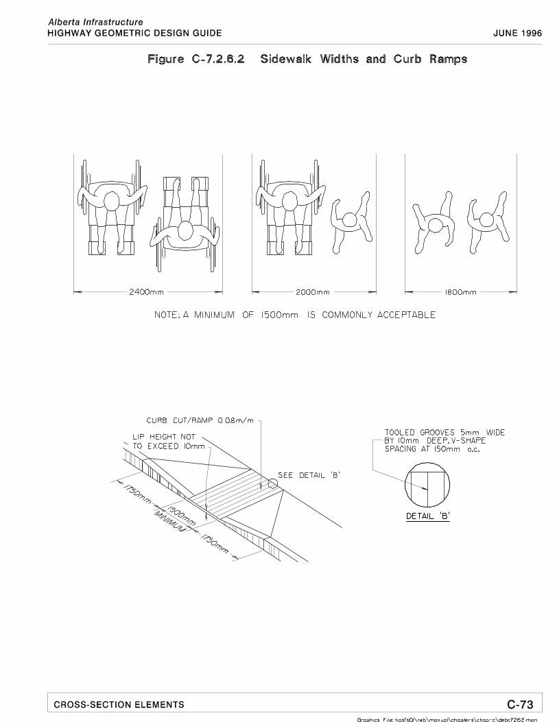
$ The desirable clear walkway width is 1.8 m, although a minimum width of 1.5 m iscommonly acceptable.
$ In areas near hospitals and seniors' homes where wheelchairs users are morecommon on walkways, additional width may be required as illustrated in Figure C-7.2.6.4.
11
10.2 Curb Ramps
Sidewalk curbs (and raised islands) remain the single most common and difficult barrier inthe path of travel for persons with reduced mobility to negotiate. Any level change withoutthe aid of a ramp would pose a mobility barrier. It is important that curb cuts/ramps areprovided at all points of level change in the path of travel.
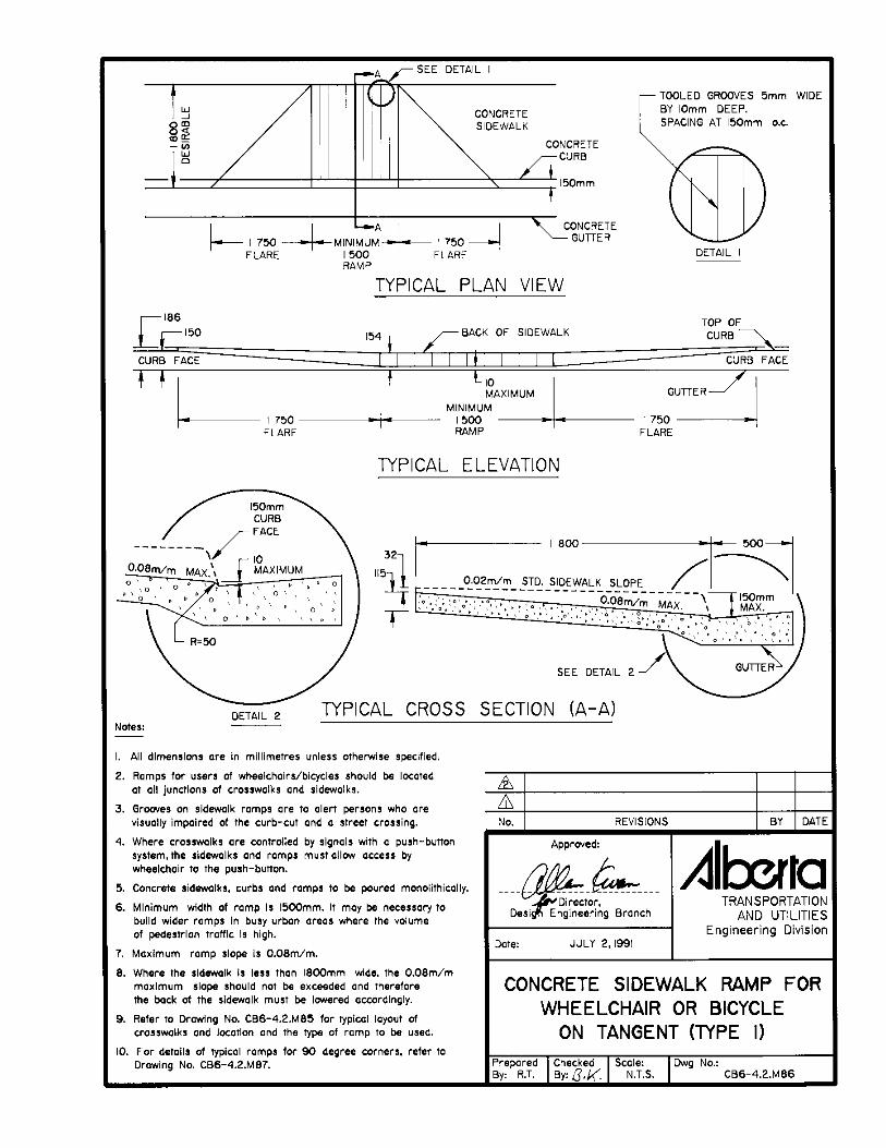
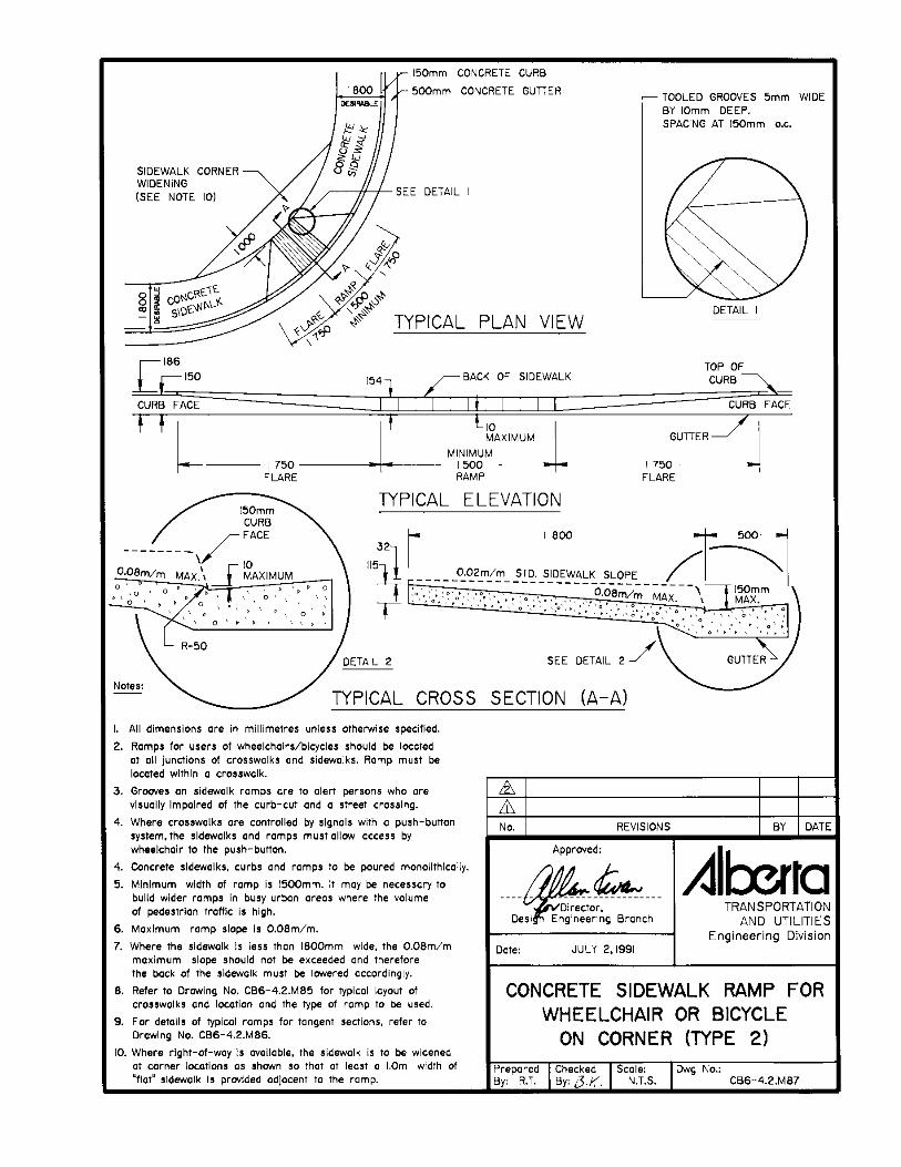
Curb ramp standards developed by Alberta Transportation and Utilities are shown inFigure C-7.2.6.2. and on Figure CB6-4.2MB6 in Appendix I. The key elements aresummarized as follows.
Design considerations:
$ Curb ramps at intersections must be located within crosswalks. Persons usingwheelchairs must be able to use the ramps safely away from the travel path ofvehicular traffic.
$ Ideally, the bottom of the ramp should have a cane-detectable lip. The maximumrise for that lip is 10 mm to allow a smooth path for wheelchairs. See Figure C-7.2.6.2. and on Figure CB6-4.2MB6 in Appendix I for illustration.
$ All raised platforms/islands in transit centres must have curb ramps andappropriate ramp access into the transit centre from the adjacent pedestrian system.
12
10.3 Bus Stop Location
The location of bus stops relative to the origin and destination of the trip is important toaccessibility of the system. To some users, the walking distance to a bus stop may well bethe major barrier to accessing the conventional transit system. Planning for bus routes andlocation of bus stops should be an essential and integral part of any major developmentplanning.
Design considerations:$ areas near seniors' homes, hospitals, institutions and other high transit usage
locations, bus stops should be located as close to these facilities as practicallypossible to reduce walking distances. Conversely, developers of seniors' homes andhigh density developments should consider locating their facilities close to transitroutes/stops.
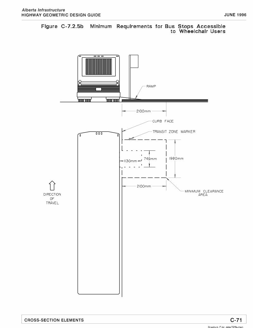
$ The minimum obstruction clearance area to accommodate the deployment(lowering) of the wheelchair ramp from the bus and to allow for wheelchairmovement after clearing the ramp is 2.1 m by 1.98 m, as shown on Figure C-7.2.5b. This minimum clearance area is based on the current bus ramp specifications andwheelchair design envelope.
$ The waiting pad or street-side sidewalk at the bus stop should have a minimumlength of 8.5 m, a minimum width of 2.1 m, and a barrier type curb height of150 mm. Those transit systems with articulated buses may need to consider a longerbus pad.
$ The 2.1 m width is considered to be a practical minimum requirement, sufficient toallow a wheelchair user to get on and off a bus. If the bus stop is expected toaccommodate scooters or a high number of patrons, a wider (2.4 m) bus pad shouldbe considered.
$ At locations where more than one route uses a bus stop and the frequency of morethan one bus stopping simultaneously at the same stop is high, an additional 17.3 m(12.3 m for vehicle length and 5 m pull-out space) should be added to the length ofthe concrete pad for each additional bus simultaneously using the stop.
$ The bus pad should be clear of any obstacles, such as benches, newspaper boxes,garbage containers, trees and other street furniture. Regular maintenance isimportant to remove snow, ice and other debris.
$ Bus stops should be located on sections of tangent and relatively flat roadway, andstops on steep slopes should be avoided.
14
10.4 Bus Stops
Bus stops and shelters are comprised of a number of individual elements that must beplanned in a coordinated manner. There are a variety of road right-of-way conditions in amunicipality. Each bus stop and shelter must be designed to meet the users' needs withinthe available right-of-way conditions and be compatible with the neighbourhoodenvironment.
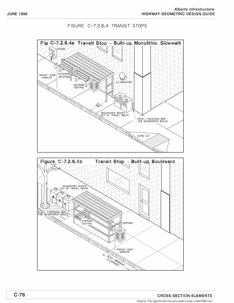
Figures 4 to 8 illustrate suggested bus stop and shelter arrangements in a variety ofsidewalk and boulevard conditions in built-up and suburban locations. The suggestedguidelines are flexible and may be tailored to the sidewalk and boulevard conditions at aparticular stop. It is not possible to show every bus stop situation; however, these exhibitsattempt to illustrate the principles of designing accessible bus stops. The exhibits arebriefly described as follows:
Figure C-7.2.6.4a. shows a bus stop in a built-up area, such as central business districts,where the sidewalk occupies the space between the road and adjacent buildings.
Figure C-7.2.6.4b. shows a bus stop in a built-up area, where the sidewalk is separated by aboulevard from the road. Note that the placement of the shelter does not interfere with thesidewalk.
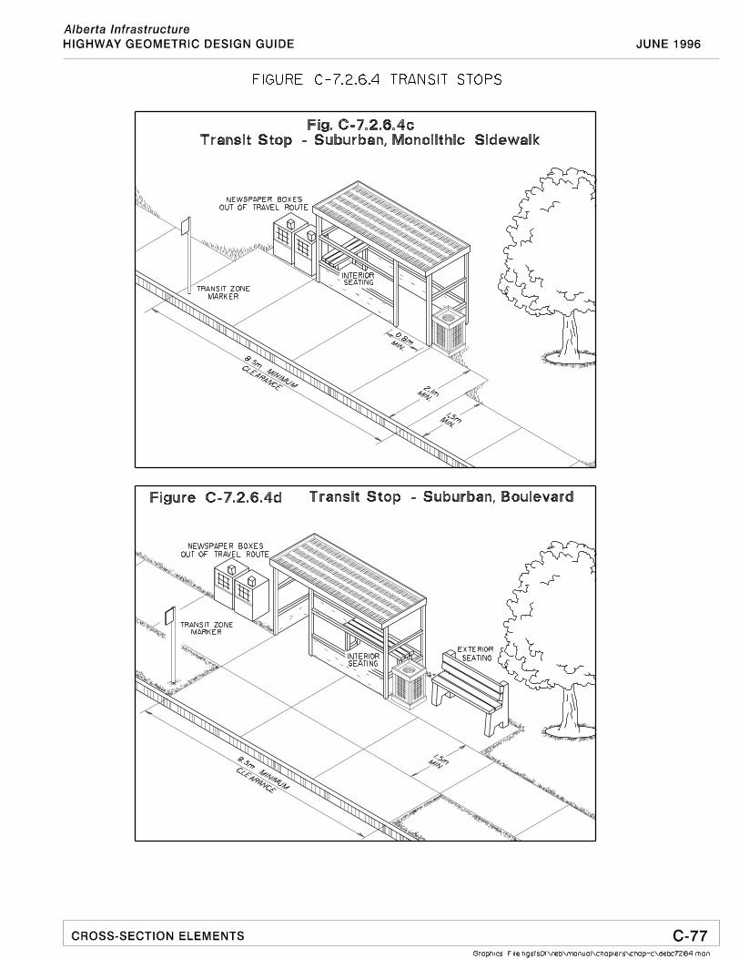
Figure C-7.2.6.4c. is a bus stop in a suburban area, where there is no boulevard separatingthe sidewalk from the road. The width of the bus pad is a minimum of 2.1 m, as comparedto the 1.5 m width of the sidewalk.
Figure C-7.2.6.4d. shows a bus stop in a suburban area with a boulevard separating thesidewalk from the road. The sidewalk is part of the bus pad.
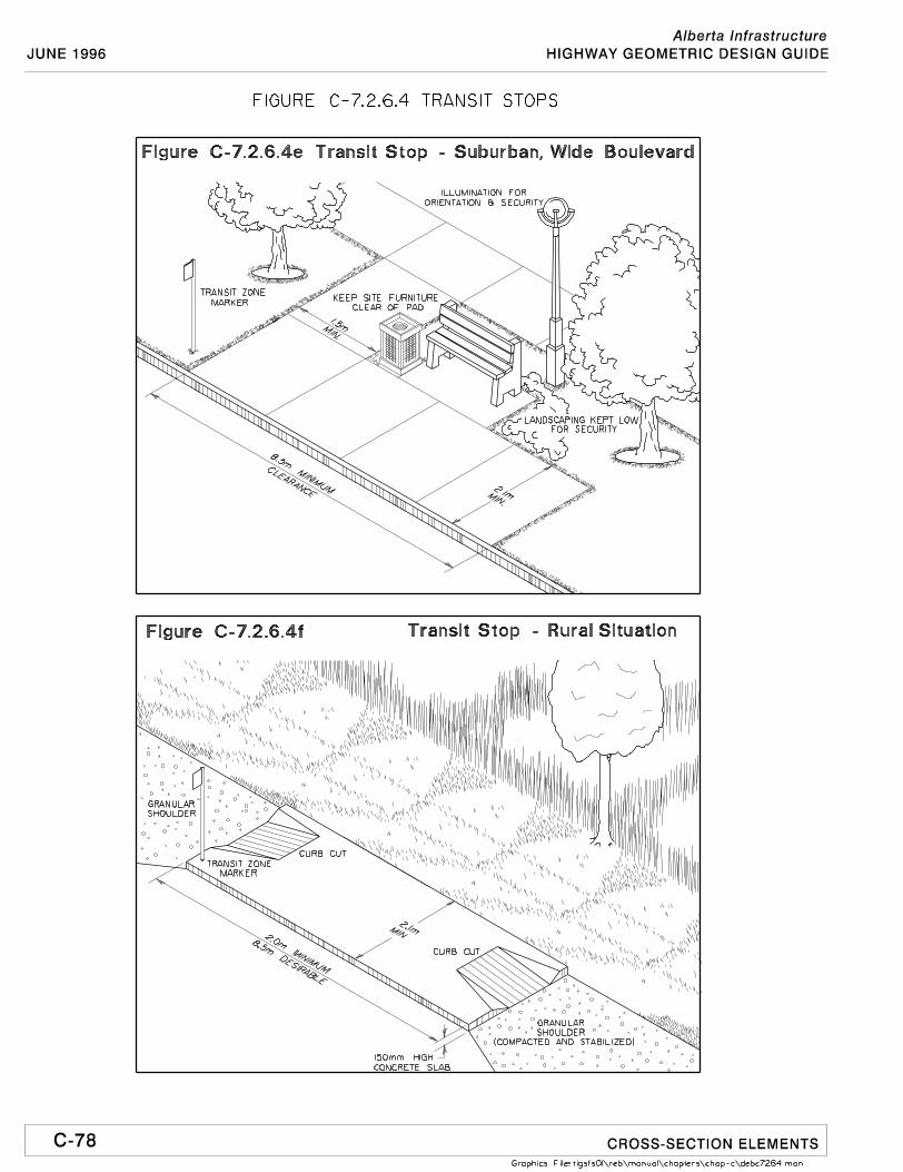
Figure C-7.2.6.4e. illustrates a bus stop in a suburban area with a wide boulevard (morethan 2.1 m). A walkway is needed to connect the bus pad and the sidewalk.
Design considerations:
$ Provide a non-slip, solid, smooth, well drained (desirable cross slope of 2%), andpaved (usually with concrete) area around the shelter and with connections toadjacent walkways.
$ Locate street furniture and signing to keep pedestrian access free of obstructions.
$ Eliminate any level changes/steps between the bus pad and the shelter.
$ If on-street parking adjacent to the bus stop is allowed, the transit zone may beextended by locating the transit zone marker 5 m ahead of the bus pad, to provide apull-out space.
$ Illuminate bus stop areas for orientation and security.
$ Signing must be easily recognizable and legible.15
10.5 Shelters
Bus shelters primarily provide overhead protection and a certain degree of climaticprotection. Shelters vary in materials and dimensions. Many of them are funded orprovided by advertising companies for the return of the right to display advertising on theshelters. Municipalities should specify the standards and location of the shelters in thecontracts with these companies, so that good design and location criteria are notcompromised by the involvement of commercial interests.
Design considerations:
$ Shelter dimensions vary. A size of 3 m long and 1.5 m wide is quite common.
$ Shelters should be designed with transparent sides for visibility and security.
$ Include transit route maps, schedules, and seating in shelters. Maps and schedulesshould be easily readable by persons using wheelchairs and, to the extent possible,persons with a visual impairment.
$ Glass panels should be marked with horizontal contrasting strips.
$ Provide seating, if feasible, with sufficient space to move around.
$ There should not be steps between the sidewalk/bus pad and the shelter.
$ Shelter openings must be a minimum of 800 mm to allow a wheelchair to passthrough.
$ Doorways and doors in enclosed shelters in major transit centres must be designedto the standards specified in the Alberta Building Code (see the Barrier-FreeDesign Guide produced by Alberta Labour).
$ Heated shelters should be considered in major transit centres.
$ Where public telephones are provided, at least one telephone should be accessibleby persons using wheelchairs. It must be located so that the receiver, coin slot andcontrol are no more than 1200 mm above the floor.
16
10.6 Seating
It is very desirable to provide seating at bus stops. Standing for even a short time may beunacceptable or even painful for some, and would impede accessibility to the transitsystem.
Seating can be provided inside or outside of bus shelters. Some may find the confinedspace inside a shelter uncomfortable, and would welcome the provision of outside seating,which may be located directly adjacent to the shelter, if one is available.
Design considerations:
$ Seating benches should be placed outside the circulation of pedestrians and shouldnot encroach upon sidewalks or bus pads.
$ Seats should be located a minimum of 600 mm from the walkways so that legs donot protrude into pedestrian traffic.
$ Typical dimensions are: 450 mm to 500 mm high and 400 mm to 500 mm deep. Lengths are determined by the availability of space.
$ Armrests of 180 mm to 250 mm above seat height are desirable.
10.7 Rural Bus Stops
There are occasions when bus stops are needed in outlying areas, where the roads haveopen drainage ditches along the sides. Figure C-7.2.6.4f. shows an accessible bus stop that can be constructed along the shoulder of the road.
If the bus stop usage is very light, the length of the raised bus pad can be shortened to aminimum of 2 m to reduce the costs. At least one curb ramp must be provided to allowwheelchairs to access the bus pad.
10.8 Signing
Unlike other traffic signs, which conform to national standards, bus zone signing istypically unique in each municipality. The following design considerations are intended toprovide some guidance on bus zone signing, and not intended to standardize signingpractices. Essentially, bus zone signing should be readily identifiable, legible, clear, andconsistent.
Design considerations:
$ For regular bus zone marker signs (about 30 cm wide and 45 cm high) situatedabove normal head level, the route number should be shown in 72 point lettering(helvetica compressed) size, with at least a 70% contrast with the sign background.
20
$ For large bus terminal marker signs (about 60 cm by 60 cm) situated above headlevel, the route number should be shown in 432 point lettering or about 15 cm inheight (helvetica bold) size, with at least a 70% contrast with the sign background.
$ Some bus zone marker signs, which do not extend beyond the edges of theirsupport post or structure, may be located at eye level, providing a person may havea clear path of travel up to the sign.
$ Schedule information must be well situated to allow approach by a person using awheelchair and an initial or preferred approach by a person with a visualimpairment.
$ For name or identification signs, high contrast titles of significant bus zones maybe situated at a height of about 1500 mm above the ground level and in at least0.75 mm relief above the background (helvetica medium or similar lettering). Thelettering should have a height of no less than 50 mm (X-height).
$ For easy identification of a bus zone, it is desirable to have a pictorialrepresentation of a bus on the signs.
10.9 Tactile Warning Strips
The use of tactile warning strips has been briefly discussed in Section 5. Tactile warningstrips are used specifically for warning an individual with a visual impairment that anobstruction (or in most cases a substantial change in elevation) is located within theperson's immediate path of travel. Warning strips are not generally used for wayfindingsystems.
Research work is continuing in finding effective wayfinding tactile cues which will beeasily differentiated from warning surfaces. Until such work is completed, tactile warningstrips must only be installed where a significant change in elevation exists (for example,train platforms, the top landings of stairs and docks). Any other application of warningstrips will only create confusion in safety related situations.
Tactile warning strips are not considered necessary at bus stops. Other methods ofeffective wayfinding may be used for bus stops, such as effective placement of streetfurnishings and/or shelters (see Figure C-7.2.6.4f.), to naturally guide the flow ofpedestrian traffic.
21
11.0 Bus Transfer Stations
11.1 Introduction
In the summer of 1996, the Minister's Advisory Committee Meeting on AccessibleTransportation, requested the subcommittee to extend their assignment to reviewaccessiblility of bus transfer stations.
Since the introduction of low-floor buses to public transit bus fleets, more people withmobility aids are using public transit. Some complaints are being raised about inherantdesign deficiencies in existing transfer stations, those with and without buildings, makingaccess difficult to persons with disabilities.
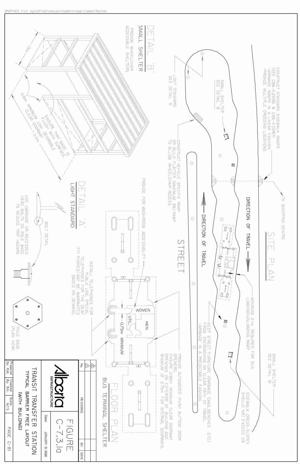
As a result of a site inspection made jointly by selected members of the AdvisoryCommittee and department officials from Alberta Transportation and Utilities, a detailedlist of observed deficiencies was prepared. Using the information from the Guidelines forDesign of Safe Accessible Environments and the original Design Guidelines forAccessible Bus Stops recommendations were drafted and incorporated into Figures C-7.3.1a. and C-7.3.1b. The previously prepared Design Guidelines forAccessible Bus Stopsis now expanded to incorporate desireable and recommended features for Bus TransferStations.
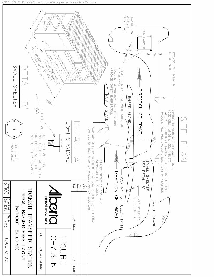
Two types of bus transfer stations are illustrated in these extended guidelines:
- Transfer Stations with buildings, and- Transfer Stations without buildings.
11.2 Buildings and Shelter Features
Buildings should be accessible around the perimeter with at least 1.5 m of relatively levelwalkway. The exterior doors of the building should be provided with automated (push-button) door openers with a minimum clear opening of 0.9 m. All internal doorwaysshould have a minimum width of 0.75 m. Washroom accessibility should be included. Placement height of accessible public telephones is critical. There may be more of a needfor access to telephones for persons with disabilities than able-bodied patrons.
Transfer stations without a shelter building are usually constructed on smaller morecompact sites. The requirements for the proper placement and alignment of curb ramps isvery critical. Figure C-7.3.1b. demonstrates how other fixtures should be placed to allow aminimum path of travel of 1.5 m width.
22
Small shelters should be accessible. Existing shelters have floors which are constructedwith a 4 X 8 foot X 1/2" thick plywood on a 2 X 4 frame. The 101 mm (4") high lip at thedoorway cannot be mounted by scooters or wheelchairs. It is recommended that at thedoorway the floor be flat with the outside slab or a ramp be constructed which will allowwheelchairs or scooters to travel on and enter the shelter. The recommended 1.5 m shelterwidth allows wheelchairs freedom to manoeuvre within the structure.
11.3 Curb Ramps
Please refer to previous guidelines which address this feature.
Because most transfer stations are placed in or adjacent to shopping centres, care should beexercised in placing curb ramps and aligning them for a direct path of travel to theshopping centre.
11.4 Streetscape Features
It is important to keep streetscape fixtures like garbage containers, benches etc, fromencroaching on clear path of travel. Please refer to Figures C-7.2.6.4e. and C-7.2.6.4f. forrecommended placement of fixtures.
11.5 Street Lights and Bus Stop Signs
For persons with visual disabilities, light standard and bus stop bases should not have anybolts protruding from the base. It is recommended that recessed heads be installed for allbases. Placement of poles should either be near the curb or completely out of the path oftravel.
23
12.0 Summary
The introduction of low-floor buses in transit systems is a significant step in providing a barrier-freetransportation environment. It is equally important to provide an accessible bus stop and accessibletransfer stations. A barrier-free path of travel is necessary between the bus stop/transfer station andthe origin/destination of the trip.
These guidelines are directed toward the design of new bus stops and transfer stations as well asretrofitting of existing facilities. Many bus stops and transfer stations in Alberta cities are notconsidered to be "accessible" in a strict sense, and, in addition, many sidewalks have no curb ramps. Under the present economic climate, retrofitting of existing bus stops and bus transfer stations willtake some time and political will to realize. Changes will be incremental, staged over time and on apriority basis. Nevertheless, some improvements could be achieved with minimal investment. Asimple rearrangement of bus stop/street furniture or removal of unnecessary obstructions couldmean significant improvements to accessibility for all users.
Design of new bus stops and bus transfer stations should follow these guidelines. It is recognizedthat it may not be feasible to provide a 2.1 m wide concrete pad at some bus stops. Existingtransfer stations, with heated shelters, may be retrofitted with desireable accessible features withcurrently available technology. Automated (push button) door openers could be installed in allstations over time as budgets permit. Pathway widening requiring major concrete work would bemore difficult to schedule, but would greatly assist in improving accessibility. The intent is toencourage designers to use the principles of these guidelines to maximize accessibility within theavailable right-of-way space and funding resources.
In addition to appropriate design, another aspect that requires attention on an ongoing basis isregular maintenance and upkeep of the established barrier-free paths of travel. This is particularlyimportant during winter conditions when snow, ice or other debris present obstacles to accessingtransit stops. Coordination and cooperation between the transit system and city's public worksoperations becomes essential.
24
APPENDIX I
ALBERTA TRANSPORTATION AND UTILITIES
CURB RAMP AND SIDEWALK STANDARDS
APPENDIX II
LIST OF RESOURCE PUBLICATIONSAlberta Labour
"Barrier-Free Design Guide" (Based on the 1990 Alberta BuildingCode), Edmonton, Alberta.
BC Transit
"Design Guidelines for Accessible Bus Stops" (Adapted fromOntario's guidelines), Victoria, B.C., Undated.
Canadian National Institute for the Blind
"Access Needs of Blind and Visually Impaired Travellers inTransportation Terminals: A Study and Design Guidelines", Preparedfor the Transportation Development Centre of Transport Canada,Toronto, Ontario, December 1987.
UMA Engineering Ltd. and Walker, Wright, Young Associates Ltd.
"Transit Related Community Planning Issues", Prepared for theGovernment of Ontario and various municipalities in Ontario, Toronto,Ontario, October 1989.

END