Embed Size (px)
Citation preview
GL-7.16
PROJECT INFORMATION APPROVAL STAMPProject: q Approved
Address: q Approved as noted
Contractor: q Not approved
Engineer: Remarks:
Submittal Date:
Notes 1:
Notes 2:
COUPLINGS
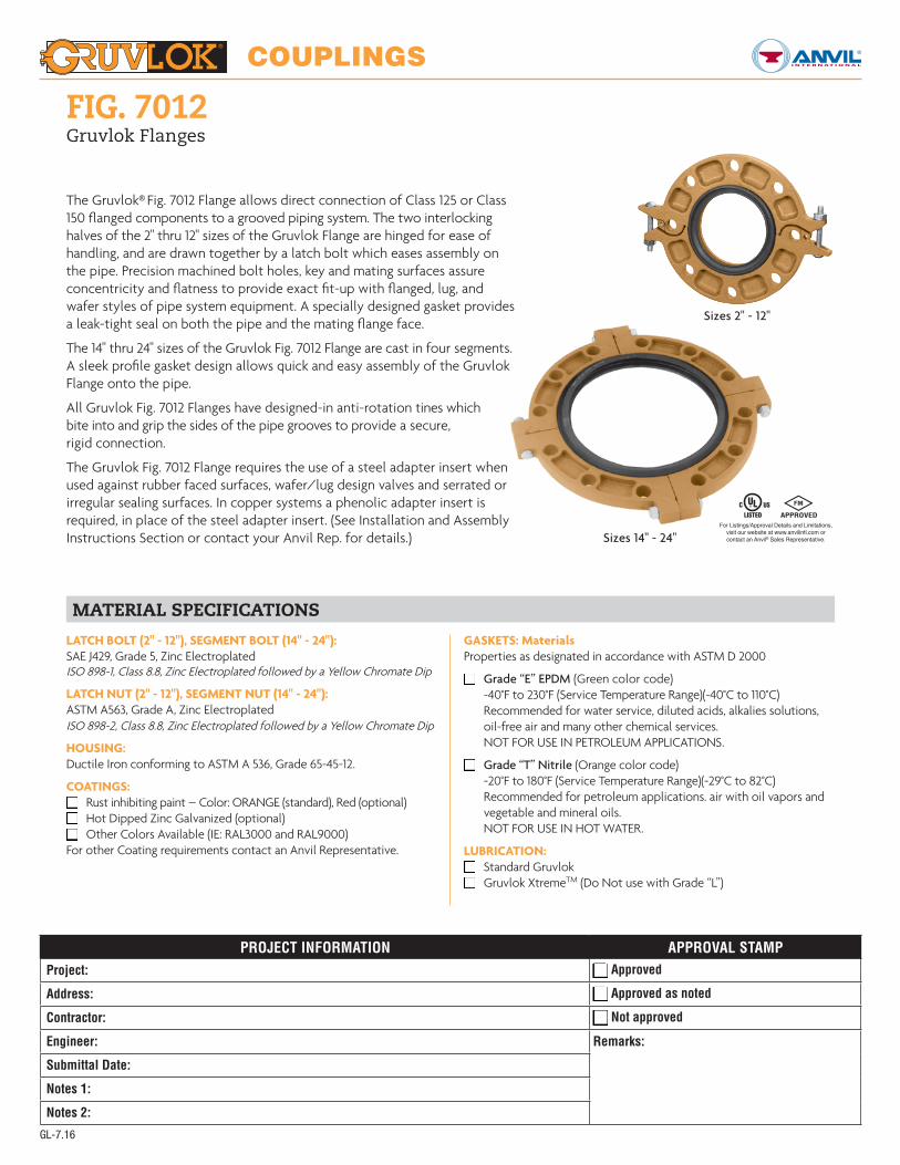
FIG. 7012Gruvlok Flanges
The Gruvlok® Fig. 7012 Flange allows direct connection of Class 125 or Class 150 flanged components to a grooved piping system. The two interlocking halves of the 2" thru 12" sizes of the Gruvlok Flange are hinged for ease of handling, and are drawn together by a latch bolt which eases assembly on the pipe. Precision machined bolt holes, key and mating surfaces assure concentricity and flatness to provide exact fit-up with flanged, lug, and wafer styles of pipe system equipment. A specially designed gasket provides a leak-tight seal on both the pipe and the mating flange face.
The 14" thru 24" sizes of the Gruvlok Fig. 7012 Flange are cast in four segments. A sleek profile gasket design allows quick and easy assembly of the Gruvlok Flange onto the pipe.
All Gruvlok Fig. 7012 Flanges have designed-in anti-rotation tines whichbite into and grip the sides of the pipe grooves to provide a secure,rigid connection.
The Gruvlok Fig. 7012 Flange requires the use of a steel adapter insert when used against rubber faced surfaces, wafer/lug design valves and serrated or irregular sealing surfaces. In copper systems a phenolic adapter insert is required, in place of the steel adapter insert. (See Installation and Assembly Instructions Section or contact your Anvil Rep. for details.)
MATERIAL SPECIFICATIONS
Sizes 2" - 12"
Sizes 14" - 24"For Listings/Approval Details and Limitations,
visit our website at www.anvilintl.com orcontact an Anvil® Sales Representative.
LATCH BOLT (2" - 12"), SEGMENT BOLT (14" - 24"):SAE J429, Grade 5, Zinc ElectroplatedISO 898-1, Class 8.8, Zinc Electroplated followed by a Yellow Chromate Dip
LATCH NUT (2" - 12"), SEGMENT NUT (14" - 24"):ASTM A563, Grade A, Zinc ElectroplatedISO 898-2, Class 8.8, Zinc Electroplated followed by a Yellow Chromate Dip
HOUSING:Ductile Iron conforming to ASTM A 536, Grade 65-45-12.
COATINGS:q Rust inhibiting paint – Color: ORANGE (standard), Red (optional)q Hot Dipped Zinc Galvanized (optional)q Other Colors Available (IE: RAL3000 and RAL9000)For other Coating requirements contact an Anvil Representative.
GASKETS: MaterialsProperties as designated in accordance with ASTM D 2000
q Grade “E” EPDM (Green color code) -40°F to 230°F (Service Temperature Range)(-40°C to 110°C) Recommended for water service, diluted acids, alkalies solutions, oil-free air and many other chemical services. NOT FOR USE IN PETROLEUM APPLICATIONS.
q Grade “T” Nitrile (Orange color code) -20°F to 180°F (Service Temperature Range)(-29°C to 82°C) Recommended for petroleum applications. air with oil vapors and
vegetable and mineral oils. NOT FOR USE IN HOT WATER.
LUBRICATION:q Standard Gruvlokq Gruvlok XtremeTM (Do Not use with Grade “L”)

COUPLINGS
GL-9.15
FIG. 7012Gruvlok Flanges
2"-12" sizes 14"-24" sizes
GRUVLOK FIGURE 7012 FLANGE: ANSI CLASS 150 OR ISO PN10 OR PN16 BOLT PATTERNS
Nominal Size O.D.
Max. Working
Pressure†
Max. End Load▼
Latch Bolt Dimensions Sealing Surface Mating Flange BoltsApprox. Wt. Ea.Latch Bolt Size*
Specified Torque §X Y Z A Max. B Min.
Mating Flange Bolts Bolt Circle Diameter
Bolt Hole Diameter
Specified Torque §
Min. Max. Qty. ANSI Size (ANSI) Min. Max.
In./DN(mm) In./mm PSI/bar Lbs./kN In./mm Ft.-Lbs/N-m In./mm In./mm In./mm In./mm In./mm PN10 (16) in. (ISO) mm In./mm In./mm Ft.-Lbs/N-m Lbs./Kg
2 2.375 300 1,329 3⁄8 x 23⁄4 30 45 61⁄4 83⁄8 3⁄4 23⁄8 37⁄16 4 5⁄8 x 23⁄4 43⁄4 3⁄4 110 140 4.250 60.3 20.7 5.91 M10 x 70 40 60 159 213 19 60 87 4 M16 x 70 120.7 19.1 149 190 1.9
21⁄2 2.875 300 1,948 3⁄8 x 23⁄4 30 45 7 91⁄2 3⁄4 27⁄8 4 4 5⁄8 x 23⁄4 51⁄2 3⁄4 110 140 4.665 73.0 20.7 8.66 M10 x 70 40 60 178 241 19 73 102 - M16 x 70 139.7 19.1 149 190 2.1
3 O.D. 2.996 300 2,115 - 30 45 7 1⁄4 9 3⁄4 3⁄4 3 4 1⁄8 - - - - 110 140 4.8
76.1 76.1 20.7 9.41 M10 x 70 40 60 184 248 19 76 105 4 M16 x 70 - - 149 190 2.23 3.500 300 2,886 3⁄8 x 23⁄4 30 45 77⁄8 101⁄2 3⁄4 31⁄2 49⁄16 4 5⁄8 x 23⁄4 6 3⁄4 110 140 6.0
88.9 88.9 20.7 12.84 M10 x 70 40 60 200 267 19 89 116 8 M16 x 70 152.4 19.1 149 190 2.7
4 4.500 300 4,771 3⁄8 x 23⁄4 30 45 9 111⁄2 3⁄4 41⁄2 59⁄16 8 5⁄8 x 23⁄4 71⁄2 3⁄4 110 140 6.3100 114.3 20.7 21.22 M10 x 70 40 60 229 292 19 114 141 8 M16 x 70 190.5 19.1 149 190 2.9
51⁄2 O.D. 5.500 300 7,127 - 30 45 9 7⁄8 12 7⁄8 7⁄8 5 9⁄16 6 3⁄4 - - - - 220 250 15.6
139.7 139.7 20.7 31.70 M10 x 70 40 60 251 327 22 141 171 8 M16 x 75 - - 298 339 7.15 5.563 300 7,292 3⁄8 x 23⁄4 30 45 10 121⁄2 7⁄8 59⁄16 63⁄4 8 3⁄4 x 27⁄8 81⁄2 7⁄8 220 250 8.8
125 141.3 20.7 32.44 M10 x 70 40 60 254 318 22 141 171 - - 215.9 22.2 298 339 4.0
61⁄2 O.D. 6.500 300 9,955 - 30 45 111⁄4 14 7⁄8 6 5⁄8 7 13⁄16 - - - - 220 250 9.7
165.1 165.1 20.7 44.28 M10 x 70 40 60 286 356 22 168 198 8 M20 x 80 - - 298 339 4.46 6.625 300 10,341 3⁄8 x 23⁄4 30 45 11 14 7⁄8 65⁄8 713⁄16 8 3⁄4 x 31⁄8 91⁄2 7⁄8 220 250 9.6
150 168.3 20.7 46.00 M10 x 70 40 60 279 356 22 168 198 8 M20 x 80 241.1 22.2 298 339 4.4
8 8.625 300 17,528 3⁄8 x 23⁄4 30 45 131⁄2 161⁄2 1 85⁄8 10 8 3⁄4 x 31⁄4 113⁄4 7⁄8 220 250 15.6200 219.1 20.7 77.97 M10 x 70 40 60 343 419 25 219 254 8 (12) M20 x 80 298.5 22.2 298 339 7.1
10 10.750 300 27,229 3⁄8 x 23⁄4 30 45 16 19 1 103⁄4 121⁄8 12 7⁄8 x 31⁄2 141⁄4 1 320 400 18.2250 273.1 20.7 121.12 M10 x 70 40 60 406 483 25 273 308 12 M20 x 90 362.0 25.4 439 542 8.3
12 12.750 300 38,303 3⁄8 x 23⁄4 30 45 19 213⁄4 11⁄4 123⁄4 141⁄8 12 7⁄8 x 33⁄4 17 1 320 400 29.9300 323.9 20.7 170.38 M10 x 70 40 60 483 552 32 324 359 12 - 431.8 25.4 439 542 13.6
14 14.000 300 46,181 5⁄8 x 41⁄4 100 130 21 24 11⁄2 14 16 12 1 x 41⁄4 183⁄4 11⁄8 360 520 52.5350 355.6 20.7 205.43 - 136 176 533 610 38 356 406 - - 476.3 28.6 488 705 23.8
16 16.000 300 60,319 5⁄8 x 41⁄4 100 130 231⁄2 261⁄2 11⁄2 16 18 16 1 x 41⁄4 211⁄4 11⁄8 360 520 67.0400 406.4 20.7 268.31 - 136 176 597 673 38 406 457 - - 539.8 28.6 488 705 30.4
18 18.000 300 76,341 3⁄4 x 5 130 180 25 29 15⁄8 18 20 16 11⁄8 x 43⁄4 223⁄4 11⁄4 450 725 82.5450 457.2 20.7 339.58 - 176 244 635 737 41 457 508 - – 577.9 31.8 610 983 37.4
20 20.000 300 94,248 3⁄4 x 5 130 180 271⁄2 311⁄2 13⁄4 20 22 20 11⁄8 x 43⁄4 25 11⁄4 450 725 106.5500 508.0 20.7 419.23 - 176 244 699 800 44 508 559 - – 635.0 31.8 610 983 48.3
24 24.000 250 113,097 7⁄8 x 51⁄2 180 220 32 361⁄2 17⁄8 24 26 20 11⁄4 x 51⁄2 291⁄2 13⁄8 620 1,000 138.5600 609.6 17.2 503.08 - 244 298 813 927 48 610 660 - - 749.3 34.92 841 1,356 62.8
Mating Flange
NOTES:† Maximum Working Pressure Rating is for schedule 40 steel pipe. For light wall, stainless steel, aluminum and ISO pipe pressure ratings, please refer to the technical data section. The Gruvlok Flange bolt hole pattern conforms to ANSI Class 150 and Class 125 flanges.To avoid interference issues, flanges cannot be assembled directly to Series 7700 butterfly valve. Flange can be assembled to one side of series 7500 and 7600 valve only.Mating flange bolts must be at least Intermediate Strength Bolting per ASME B16.5. Bolts with material properties equal or greater than SAE J429 Grade 5 are acceptable.
For additional details see “Coupling Data Chart Notes” in the Introduction Section of the Gruvlok Catalog.+ PN 16 uses M24 x 90 (PN) Dimensions for bolt circle PN 10 & 16 Flange.* Available in ANSI or metric bolt sizes only as indicated.▼ Based on use with standard wall pipe.§ – For additional Bolt Torque information, see the Technical Data Section of the Gruvlok Catalog.See Installation & Assembly directions on following pages.

COUPLINGS
GL-5.13
FIG. 7012Gruvlok Flanges
A. The sealing surfaces A Max. to B Min. of the mating flange must be free from gouges, undulations and deformities of any type to ensure proper sealing of the gasket.
B. Gruvlok Flanges are to be assembled on butterfly valves so as not to interfere with actuator or handle operation.
C. Do not use Gruvlok Flanges within 90 degrees of one another on standard fittings because the outside dimensions may cause interference.
D. Gruvlok Flanges should not be used as anchor points for tierods across non-restrained joints.
E. Fig. 7012 Gruvlok Flange sealing gaskets require a hard flat surface for adequate sealing. The use of a Gruvlok Flange Adapter Insert is required for applications against rubber faced valves or other equipment. The Gruvlok Flange Adapter Insert is installed between the Gruvlok Flange sealing gasket and the mating flange or surface to provide a good sealing surface area.
F. Gruvlok Flanges are not recommended for use against formed rubber flanges.
G. Contact an Anvil Representative for Di-Electric Flange connections.
Applications which require a Gruvlok Flange Adapter Insert:
1. When mating to a wafer valve (lug valve), if the valve is rubber faced in the area designated by the sealing surface dimensions (A Max. to B Min.), place the Gruvlok Flange Adapter Insert between the valve and the Gruvlok flange.
2. When mating to a rubber-faced metal flange, the Gruvlok Flange Adapter Insert is placed between the Gruvlok Flange and the rubber-faced flange.
3. When mating to a serrated flange surface, a standard full-faced flange gasket is installed against the serrated flange face and the Gruvlok Flange Adapter Insert is placed between the Gruvlok Flange and the standard Flange gasket.
4. When mating to valves or other component equipment where the flange face has an insert, use procedure described in note 3.
Rubber Su r fac e
Mating Flange Component with Serrated Face
Mating Flange Gruvlok Figure 7012 Flange
B min. A max.
Grooved Pipe Flange Adapter Insert Flange Adapter Insert
Flange Gasket
Gruvlok Figure 7012 Flange
Grooved Pipe
Mating Flange
COUPLINGS
FIG. 7012Gruvlok Flange (2"–12")
APPLICATIONS WHICH REQUIRE A GRUVLOK® FLANGE ADAPTER INSERT:
1. When mating to a wafer valve (lug valve), if the valve is rubber faced in the area designated by the sealing surface dimensions (A Max. to B Min.), place the Gruvlok Flange Adapter Insert between the valve and the Gruvlok Flange.
2. When mating to a rubber-faced metal flange, the Gruvlok Flange Adapter Insert is placed between the Gruvlok Flange and the rubber-faced flange.
3. When mating to a serrated flange surface, a standard full-faced flange gasket is installed against the serrated flange face, and the Gruvlok Flange Adapter Insert is placed between the Gruvlok Flange and the standard flange gasket.
4. When mating to valves or other component equipment where the flange face has an insert, use procedure described in note 3.
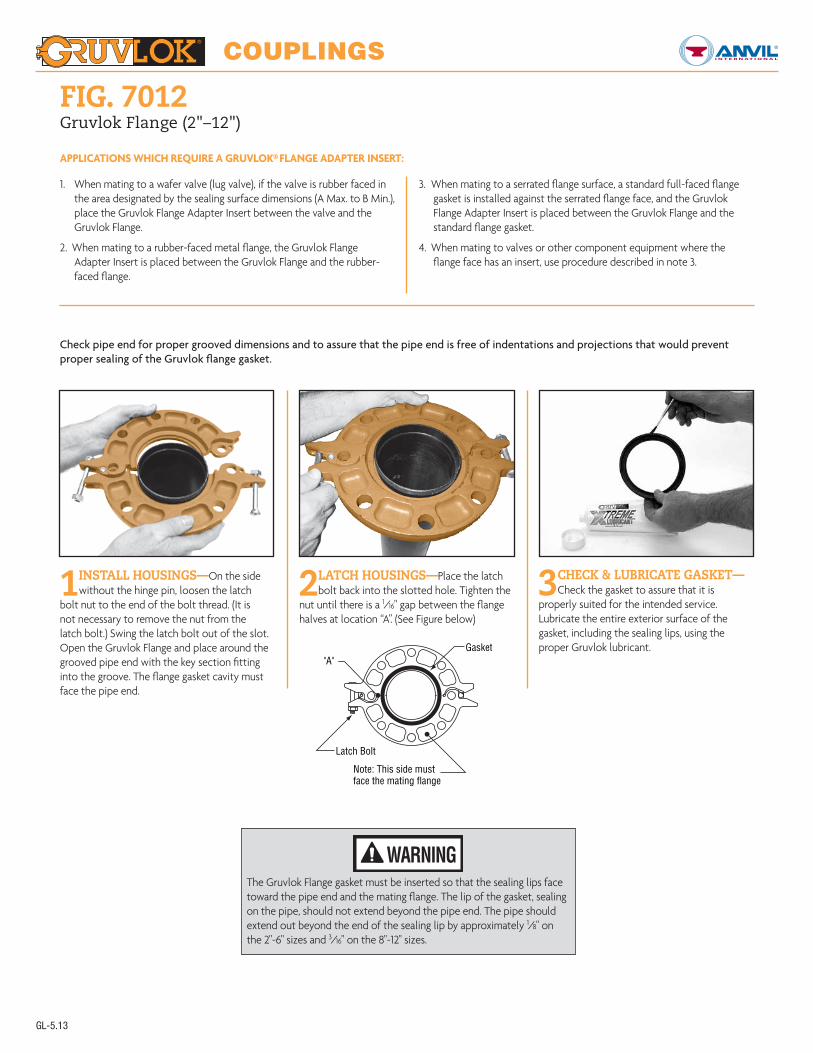
Check pipe end for proper grooved dimensions and to assure that the pipe end is free of indentations and projections that would prevent proper sealing of the Gruvlok flange gasket.
1 INSTALL HOUSINGS—On the side without the hinge pin, loosen the latch
bolt nut to the end of the bolt thread. (It is not necessary to remove the nut from the latch bolt.) Swing the latch bolt out of the slot. Open the Gruvlok Flange and place around the grooved pipe end with the key section fitting into the groove. The flange gasket cavity must face the pipe end.
2 LATCH HOUSINGS—Place the latch bolt back into the slotted hole. Tighten the
nut until there is a 1/16" gap between the flange halves at location “A”. (See Figure below)
3 CHECK & LUBRICATE GASKET—Check the gasket to assure that it is
properly suited for the intended service. Lubricate the entire exterior surface of the gasket, including the sealing lips, using the proper Gruvlok lubricant.
The Gruvlok Flange gasket must be inserted so that the sealing lips face toward the pipe end and the mating flange. The lip of the gasket, sealing on the pipe, should not extend beyond the pipe end. The pipe should extend out beyond the end of the sealing lip by approximately 1/8" on the 2"-6" sizes and 3/16" on the 8"-12" sizes.
WARNING
"A"
Latch Bolt
Gasket
Note: This side mustface the mating flange
GL-5.13

COUPLINGS
GL-3.14
4 INSTALL GASKET—Stretch the Gruvlok gasket around the pipe end and
then press the gasket into the cavity between the pipe O.D. and the flange. The gasket must be properly positioned as shown in the figure below.
5 LUBRICATE GASKET LIP—With the gasket in place apply lubricant to the
exposed gasket tip, which will seal on the mating flange. Tighten the nuts on the latch bolts alternately to the specified latch bolt torque. The flange housings must be in firm metal-to-metal contact.
6 INSPECT MATING FLANGE—Verify that the mating flange face is hard, flat and
smooth, free of indentations, which would prevent proper sealing of the Gruvlok Flange gasket. Assure the gasket is still in the proper position and align Gruvlok Flange bolt holes with the mating flange, pump, tank, etc., bolt holes.
FIG. 7012Gruvlok Flange (2"–12")
7 INSTALL BOLTING—Insert a flange bolt or stud with material properties of SAE J429 Grade 5 or higher through the
bolt holes and thread a nut on hand tight. Continue this procedure until all bolt holes have been fitted. Tighten the nuts alternately and evenly so the flange faces remain parallel. All the bolts or studs must be torqued to the mating flange bolts specified torque. The flange faces should have metal-to-metal contact.
It is important to line up the boltholes before bringing the two flangestogether. Sliding the flanges into place
will dislodge the gasket and cause leakage to occur. When using a flange insert, it is important that the insert is properly aligned with the gasket prior to tightening the bolts.
WARNING
NOTE: The Gruvlok Fig. 7012 Flange requires the use of a Flange Adapter Insert when used against rubber surfaces (Figure C1), serrated flange surfaces or mating flanges with inserts (Figure C2). TheFlange Adapter Insert will be exposed to the fluids in the system. Ensure that the Insert is compatible with the fluids in the systems and with adjacent piping components.
Do not use a steel Flange Adapter Insert in copper systems or in systems where galvanic corrosion is possible.
WARNING
CAUTION: Proper torquing of flange bolts is required to obtain specified performance. Over torquing the bolts may result in damage to the bolt and/or casting which could result in pipe joint separation. Under torquing the bolts may result in lower pressure retention capabilities, lower bend load capabilities, joint leakage and pipe joint separation. Pipe joint separationmay result in significant property damage and serious injury.
FIG. C1 FIG. C2

COUPLINGS
GL-3.14
FIG. 7012Gruvlok Flange (14"–24")
Gruvlok® Flanges of 14" size and larger are cast in four segments to ease handling during assembly. Figure 7012 Gruvlok Flanges should not be used with tie rods nor in a configuration with a wafer valve between two 7012 flanges.
1INSTALL HOUSING—Place each Gruvlok Flange segment around the grooved
pipe with the key section fitting into the groove and the flange gasket cavity facing the pipe end. Loosely assemble the segments using the four segment-bolts-and nuts. Alternately and equally tighten the latch bolts and nuts to the specified latch bolt torque. Bring the four flange segments into full, firm metal-to-metal contact.
NOTE: An alternative method of assembly is to loosely preassemble two segments into two equal halves of the flange leaving a small gap (approximately 1/8") between the two segments of each flange-half. Place the flange halves around the pipe and complete the assembly as described in Step 1, above.
2INSTALL GASKET—Check the gasket grade to verify that it is properly suited
for the intended service. Lubricate the entire surface of the gasket and the flange cavity using the appropriate Gruvlok Lubricant. Place the Gruvlok Flange Gasket around the pipe end by pressing the gasket into the cavity between the pipe O.D. and flange recess. Move around the gasket in both directions until the gasket is fully seated in the flange gasket cavity.
3GASKET POSITION—The correct position and relationship of the
components of the Gruvlok Flange assembly is shown in the Figure above. The wide gasket lip must seal on the pipe surface diameter and the narrow gasket lip must face the mating flange. Be careful that foreign particles do not adhere to lubricated surfaces.
NOTE: Design of the Gruvlok Flange provides sealing only with the special Gruvlok Flange gasket. Only Gruvlok Flange gaskets may be used with Fig. 7012 flanges.
4INSPECT & MATE FLANGE
Align the Gruvlok Flange bolt holes with mating flange bolt holes. Insert a flange bolt or stud with material properties of SAE J429 Grade 5 or higher through the bolt holes and thread a nut on hand tight. Insert the
next bolt or stub opposite the first and again thread the nut on hand tight. Continue this procedure until all bolt holes have been fitted. Insertion of the flange bolts prior to contact of the flanges will help in the alignment of the flanges. Pull the two flanges into contact using care to assure that the gasket remains fully seated within the gasket cavity during assembly.
NOTE: Take care to assure that the gasket lip is not bent backwards and pinched between the two flanges.
5INSTALL BOLTING
Tighten the nuts evenly to the specified mating face bolt torque so that the flange faces remain parallel and make firm even contact around the entire flange.
CAUTION: Proper torquing of flange bolts is required to obtain specified performance. Over torquing the bolts may result in damage to the bolt and/or casting which could result in pipe joint separation. Under torquing the bolts may result in lower pressure retention capabilities, lower bend load capabilities, joint leakage and pipe joint separation. Pipe joint separation may result in significant property damage and serious injury.
CAUTION:GASKET MUST BE FULLY SEATED AGAINST THESE THREE SURFACES
14" – 24" FIG. 7012GRUVLOK FLANGE
GASKET
PROPER POSITION OFGASKET SEALING LIPS
PIPE SURFACE DIAMETER