Embed Size (px)
Citation preview
Page 1 of 4
Local regulations may restrict the use of this product to below the conditions quoted. In the interests of development and improvement of the product, we reserve the right to change the specification without notice. © Copyright 2018
TRANSLATION RUN OVER
Fig 12 Sizes 3/8" and 1¼" to 2½"
Fig 12Brass and Bronze
Strainers
Fig 12Sizes ½" to 1"
DescriptionThe Fig 12 is a brass and bronze screwed Y-type strainer. The standard stainless steel screen is 0.8 mm perforations. As options, other perforations and mesh sizes are available as well as monel screens. The strainer cap can be drilled and tapped for blowdown and drain valves if required.
StandardsThis product fully complies with the requirements of the Pressure Equipment Directive (PED) and carry the mark when so required.
Certification This product is available with a manufacturer's Typical Test Report for the body and cap. Note: All certifications/inspections requirements must be stated at the time of order placement.
Sizes and pipe connectionsFig 12 Brass 3/8"Fig 12 Bronze ½", ¾", 1", 1¼", 1½", 2" and 2½"Connections: Screwed BSP (BS 21) or NPT
Optional extras
Strainer screens
Stainless steelPerforations 1.6, 3.0 mm
Mesh 40, 100, 200
MonelPerforations 0.8, 3.0 mm
Mesh 100
Blowdown or drain valve connectionsThe cap can be drilled to the following sizes to enable a blowdown or drain valve to be fitted at extra cost.
Strainer size Blowdown valve Drain valve
3/8" and ½" ¼" ¼"
¾" and 1" ½" ½"
1¼" and 1½" 1" ¾"
2" and 2½" 1¼" ¾"
TI-P164-02CMGT Issue 9

TI-P164-02CMGT Issue 9
Page 2 of 4
Fig 12 Brass and Bronze Strainers
4
1
3
2
Fig 12 Sizes 3/8" and 1¼" to 2½"
4
13
2
Fig 12Sizes ½" to 1"
Pressure bar gTe
mpe
ratu
re °
C
0 5 10 15 19* 20 25
50
100
150
210
0
Steam saturation curve
The product must not be used in this region.
Body design conditions PN25
PMA Maximum allowable pressure 25 bar g
TMA Maximum allowable temperature 210 °C
Minimum allowable temperature -198 °C
*PMO Maximum operating pressure for saturated steam service
Designed for a maximum cold hydraulic test pressure of: 38 bar g
MaterialsNo. Part Material
1 Body3/8" Brass EN 12165 CW617N
½" to 2½" Bronze EN 1982 CC491K
2 Cap Brass EN 12165 CW617N
3 Cap gasket Reinforced exfoliated graphite
4 Strainer screen Stainless steel ASTM A240 316 L
Pressure/temperature limits

Page 3 of 4
Fig 12 Brass and Bronze Strainers
TI-P164-02CMGT Issue 9
TRANSLATION RUN OVER
Kv valuesSize 3/8" ½" ¾" 1" 1¼" 1½" 2" 2½"
Perforations 0.8, 1.6 and 3 mm 2.6 3 6.2 11.3 26 41 68 98
Mesh 40 and 100 2.6 3 6.2 11.3 26 41 68 98
Mesh 200 2.6 3 6.2 9.3 21 33 55 78
For conversion:Cv (UK) = Kv x 0.963Cv (US) = Kv x 1.156
Dimensions/weights (approximate) in mm and kgBrass body
Size A B C D Screening area cm² Weight
3/8" 69 50 80 24 A/F 27 0.45
Bronze body
½" 72 54 85 30 A/F 27 0.55
¾" 82 64 110 36 A/F 43 0.70
1" 104 72 130 46 A/F 73 1.00
1¼" 138 100 170 52 A/F 135 1.60
1½" 150 110 190 60 A/F 164 2.10
2" 178 133 212 79 A/F 251 4.80
2½" 207 152 240 98 A/F 327 7.70
Safety information, installation and maintenanceFor full details see the Installation and Maintenance Instructions (IM-S26-01-EN-ISS1) supplied with the product.
Installation note:Suitable isolation valves must be installed to allow for safe maintenance and trap replacement. We also recommend that a Spirax Sarco DV depressurisation type valve (see the product specific TI literature for further details) be installed to ensure that any pressure is isolated and safely vented to atmospheric pressure before attempting to maintain the strainer.
Maintenance note:Maintenance can be completed with the strainer in the pipeline, once the safety procedures have been observed. It is recommended that a new gasket is used whenever maintenance is undertaken.
DisposalThe product is recyclable. No ecological hazard is anticipated with disposal of this product, providing due care is taken.
How to orderExample: 1 off Spirax Sarco 1½" Fig 12 bronze strainer with screwed BSP connections and stainless steel screen having 0.8 mm perforations.
Withdrawal distance
B
D
C
A

TI-P164-02CMGT Issue 9
Page 4 of 4
Fig 12 Brass and Bronze Strainers
Fig 12Sizes ½" to 1"
Fig 12Sizes 3/8" and 1¼" to 2½"
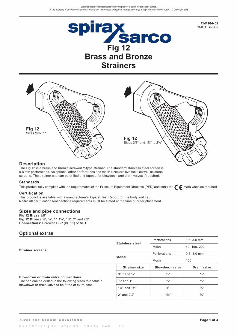
Spare partsThe spare parts available are shown in solid outline. Parts drawn in a grey line are not supplied as spares.
Available spares
Strainer screen (state material, size of perforation or mesh and size of strainer) 4
Cap gasket (packet of 3) 3
How to order sparesAlways order spares by using the description given in the column headed 'Available spares' and state the size and type of strainer and perforations or mesh required.Example: 1 - Stainless steel strainer screen having 0.8 mm perforations for a ¾" Spirax Sarco Fig 12 strainer.
3
4
2
3
4
2
Recommended tightening torques
Item Size Qty or mm N m
2
3/8"½"¾"1"
1¼"1½"2"
2½"
11111111
22 A/F 22 A/F 27 A/F 27 A/F 41 A/F 41 A/F 55 A/F 55 A/F
M28M28 M32 M42 M56 M60 M72
3¼"-16 UNS
35 - 4035 - 4042 - 4870 - 80
124 - 144164 - 184234 - 264300 - 330
5 3" 6 ¾" A/F 7/16" UNF x 1½" (38 mm) 50 - 55