Embed Size (px)
Citation preview
A Swagelok® Pre-Engineered
Subsystem
• Pre-engineeredsubsystems
availableinweeks,notmonths.
• Field-testeddesignensures
optimumsystemperformance.
• Preconditionsagassampleattheextractionpoint
• Ishighlyconfigurabletomatchprocessconditions
• Canmountdirectlytoprocessnozzles
FieldStationModuleApplicationGuide
SwagelokPre-EngineeredSubsystems
Swagelok now offers a series of
predesigned and preassembled
subsystems for use in all types of
plants and facilities where fluids are
being processed. Use Swagelok pre-
engineered subsystems to create fully
documented fluid sampling and control
systems and bring consistency to your
operations. Easy to install and operate,
these subsystems offer the high quality
and support you expect from Swagelok.
Contents
Why Use a Field Station Module? . . . . . . . . . . 3
Field Station Module Basics . . . . 5
Installing a Field Station Module . . . . . . . . . . . 6
Specifying a Field Station Module . . . . . . . . . . . . 7
Joule-Thomson Cooling Effect . . 8
Materials of Construction. . . . . . . 9
Configurations . . . . . . . . . . . . . . 10
Technical Data . . . . . . . . . . . . . . 13
Testing . . . . . . . . . . . . . . . . . . . . 13
Cleaning and Packaging . . . . . . . 13
Dimensions . . . . . . . . . . . . . . . . . 14
Enclosure Options . . . . . . . . . . . 16
Heating Options . . . . . . . . . . . . . 19
Ordering Information . . . . . . . . . . 21
Accessories . . . . . . . . . . . . . . . . 22
Regulatory Compliance . . . . . . . 24

A Swagelok Pre-Engineered Subsystem Field Station Module
3
TheSwagelokFieldStationModule(FSM)Why Use a Field Station Module?ASwagelokfieldstationmodule(FSM)reduces
processgaspressurebeforetransportingitto
ananalyzer.Transportingagassampleatlow
pressureoffersthreemajorbenefits:
• Fasteranalyzerresponsetime
• Lesscondensation
• Saferenvironment
Faster Analyzer Response Time
Inahigh-pressurelinewithdownstreamflow
control,gasmoleculesaremoredensely
populatedwhichcreatesslowerflowvelocity
andlongerpurgetimes.Loweringthepressureofagassamplemeansfewermoleculesinthe
sampletransportlineandsampleconditioningcomponents;therefore,itiseasiertoflushthe
system,andtheanalyzercanrespondfastertoprocesschanges.
Typical Swagelok Field Station Module (FSM)
A
A
P
P
FSM
Highpressureinsampletransportlineresultsinslowresponse
Lowpressureinsampletransportlineresultsinfastresponse
ManyGasMolecules Slow Response
Fast ResponseFewGasMolecules
ProcessTap
ProcessTap
Without FSM—Slow Response
Analyzer Location
Analyzer Location
With FSM—Fast Response

A Swagelok Pre-Engineered Subsystem Field Station Module
4
Theamountofgasheldinthetransportlineisproportionaltoitsabsolutepressure.Athalfthe
absolutepressure,therearehalfasmanygasmoleculesintheline,so—allotherthingsbeing
equal—ittakeshalfthetimeforafreshsampletoreachtheanalyzer.
Typically,anFSMisusedwhenprocesspressureis3bar(gauge)(43.5psig)orhigher.
Less Condensation
Therelativehumidityofagasisdirectlyproportionaltothepartialpressureofwatervaporinthe
mixture.Arelativehumidity(orsaturation)of100 %representsthemaximumpartialpressure
ofwatervaporpossibleataworkingtemperature.Therefore,ifwatervaporinanygasmixture
reaches100 %ofitssaturationlimit,watervaporwillbegintocondenseinasampletransportline.
Toavoidcondensationingassampling,theFSMreducesthepartialpressureofeverygasinthe
samplemixture.Onewaytolowerpartialpressureofeverygasistoreduceoverallsystem
pressure;thepartialpressureofeachgasdropsinproportiontotheoverallpressurechange.
Forexample,iftheabsolutepressureofasampleiscutinhalf,thepartialpressureofeachgas
inthemixtureiscutinhalfaswell,whichresultsinhalfthewatersaturationinthesample.Using
anFSMsignificantlyreducesthechanceofcondensationforminginthesampletransportline.
Safer Environment
Ifasystemiscompromised,thepressurizedgaswillexpandtoatmosphericpressurerapidly
andcancausesystemdamageorpersonalinjury.Thevolumetricexpansionratioisdirectly
proportionaltotheabsolutepressuredecrease.
Inhigh-pressuresystemswithoutfieldstationmodules,theexpansioncanbesogreatthat
theresultisexplosiveinnature.InstallinganFSMattheprocesssamplingpointmeansa
smallersectionofthesamplesystemisexposedtohighpressure,resultinginasaferoverall
environment.
P
FSM
Water Molecules

A Swagelok Pre-Engineered Subsystem Field Station Module
5
Field Station Module Basics
PR (Pressure Regulator)
ThemainpurposeofaSwagelokFSMis
toreducethepressureofanextractedgas
samplepriortotransportationtoananalyzer.
VariousSwagelokKPRseriesregulatorsare
offeredtomatchthewiderangeofsample
conditions.Thesystemvolumeupstreamofthe
regulatoriskepttoaminimumtomaintainthe
fastestresponsetimepossible.
FP (Filter-Particulate)
Itisrecommendedtofilterallsamplespriortoapressureregulator.Swagelokoffersa
widerangeofparticulatefilters(FP),membranefilters(FM),andcoalescingfilters(FC)to
accommodatevariousparticulateloadsandsamplemoisturelevels.
Whereitisdesirabletoreducehigh-pressurevolumeevenfurther,theFSMcanbeordered
withoutafilter.Inthiscase,anintegralfilterisincludedintheinletsideoftheregulator.
BV (Ball Valve)
ToallowforfastandlocalshutoffofanFSM,allconfigurationsincludeaSwagelok40Gseries
ballvalveattheinletofthesystem.
PI (Pressure Indicator)
Swagelokincludesgaugesinthreedifferentpressureindicatorlocationsforconvenient
troubleshooting.
• PI1locationmeasuresoutletpressureoftheregulator.
• OptionalPI2locationmeasuresinletpressureoftheregulator.
• OptionalPI3locationmeasuresFSMinletpressure(assumedtobeprocesspressure).
• PI2—PI1locationsmeasurethepressuredropacrosstheregulatortoensureproperregulator
function.
• PI3—PI2locationsmeasurethepressuredropacrossthefiltertohelpindicatewhenfilter
maintenanceisneeded.
RV (Relief Valve)
TheSwagelokFSMisavailablewithanoptionalproportionalreliefvalvetoguardtherestofthe
analyticalsystemfromadrasticincreaseinpressuredownstreamoftheregulator.
PR
BV
PI2
PI3
PI1
FP
RV
Inlet Outlet Vent
PR
FP
BV
BV
PI
RV
FM
FP
FM
FC
MV NV1
NV
FI
PSV
C
CV SHV
SSV
FFL
SN
PVNV
FI
PR
FP
BV
BV
PI
RV
FM
FP
FM
FC
MV NV1
NV
FI
PSV
C
CV SHV
SSV
FFL
SN
PVNV
FI
PR
FP
BV
BV
PI
RV
FM
FP
FM
FC
MV NV1
NV
FI
PSV
C
CV SHV
SSV
FFL
SN
PVNV
FI
PR
FP
BV
BV
PI
RV
FM
FP
FM
FC
MV NV1
NV
FI
PSV
C
CV SHV
SSV
FFL
SN
PVNV
FIPR
FP
BV
BV
PI
RV
FM
FP
FM
FC
MV NV1
NV
FI
PSV
C
CV SHV
SSV
FFL
SN
PVNV
FI

A Swagelok Pre-Engineered Subsystem Field Station Module
6
Installing a Field Station ModuleTheschematicbelowillustratesanFSMinstalledinaprocessline.
Forfasteranalysis,mounttheFSMontopoftheprocessnozzle(asshownabove).Ifdirect
mountingonthenozzleisimpracticalorinconvenient,installtheFSMclosetotheprocess
nozzle(asshownbelow).KeeptheconnectingtubethatlinkstheprobetotheFSMasshortas
possible.Becausetheconnectingtubecontainsgasatfullprocesspressure,itisimportantto
minimizeitsvolumetomaintainthefastestresponsetimetotheanalyzer.
Formoreinformationaboutinstallation,operation,andmaintenanceofSwagelokFSM
subsystems,seetheField Station Module User’s Manual, MS-13-218.
ASCSFLM
AFSM SCS
AFSM SCS
FieldStationModule
ProcessIsolationValve
ProcessProbe
Low-PressureSampleTransportLine
SampleConditioningSystem
ProcessAnalyzer
Analyzer LocationProcessNozzle
ProcessNozzle
ASCSFLM
AFSM SCS
AFSM SCS
FieldStationModule
ConnectingTubeatHighPressure
ProcessIsolationValve
ProcessProbe
Low-PressureSampleTransportLine
SampleConditioningSystem
ProcessAnalyzer
Analyzer Location

A Swagelok Pre-Engineered Subsystem Field Station Module
7
Specifying a Field Station ModuleTheFSMcanbecustomizedtomeetsystemrequirements.TospecifyanFSM:
• KnowthemaximuminletpressureoftheFSM.SpecifytheFSMconfigurationwiththelowest
inletpressurethatiscompatiblewiththehighestprocesspressure.
• Specifypressuregaugedialsize,placement,andfill.Themeasurementrangesofthe
pressuregaugesaredeterminedautomaticallyfromtheinletpressure.
• Swagelokselectstheregulatorthatissuitableforthemaximuminletpressure.Theoutlet
pressurecontrolrangeis0to50psig(0to3.4bar)forallmodels.
• Choosefromfivefilterorcoalesceroptions:noseparatefilter,small-orlarge-particlefilter,
membraneseparatorwithgravitydrain,andlargefibrouscoalescerwithmembranefilter.
• Coalesceroptionsworktoremoveliquidmist.Thecoalescerdrainmayterminateina
manualblowdownvalvethatisseparatefromthissystem.
• Donotuseacoalescerifthesamplecontainsmanyparticulates;thecoalescerwillclog.
Instead,specifyafiltertoremovethemand,iftheliquidmistisvolatile,keepthefield
stationandtransportlinehotenoughtoavoidcondensation.Ifnecessary,condenseand
removetheliquidinthesampleconditioningsystemclosetotheanalyzer.Ifthesample
containsmanyparticulatesandnonvolatileliquidmist,theFSMmaynotbesuitable;ask
foranevaluationbySwagelok.
• Selectfromthreepressure-reliefoptions:noreliefvalve,presetadjustablereliefvalve,or
presetadjustablereliefvalvewithmanualoverridehandle.
Caution: Without a relief valve, the outlet pressure gauge and the downstream
equipment are not protected if the pressure regulator fails. A suitable pressure
relief mechanism should be used to protect the system from overpressurization.
• Choosefromawiderangeofinletandoutletconnections,includingSwageloktubefittings,
NPTfittings,andflanges.
• Selectanenclosureoption.ABSplastic,fiberglass,and304stainlesssteelenclosuresand
sunshadesareavailable.Enclosuresareavailablewithorwithoutawindowandinsulatedor
uninsulated.

A Swagelok Pre-Engineered Subsystem Field Station Module
8
Joule-Thomson Cooling EffectFieldstationmoduleswithinletpressuresof1000psig(68.9bar)orhigherhavealargepressure
drop,andthesamplemayexperienceexcessivecooling.Althoughthetemperaturedropcaused
byJoule-Thomsoncoolingisthesameatanyflowrate,theheatitabsorbsisproportionalto
therateofflow.TheFSMoffersawiderangeofheateroptions,sufficientformostsampling
applications.
A Swagelok Pre-Engineered Subsystem Field Station Module
9
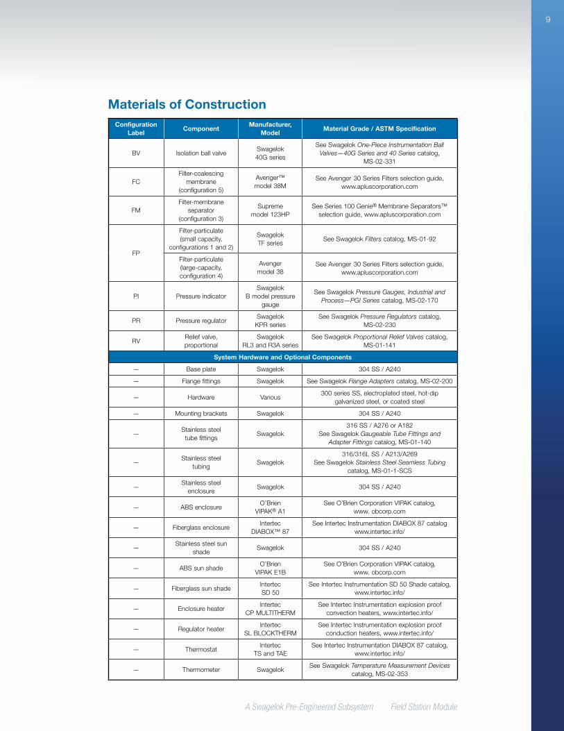
Materials of ConstructionConfiguration
LabelComponent
Manufacturer, Model
Material Grade / ASTM Specification
BV IsolationballvalveSwagelok40Gseries
SeeSwagelokOne-Piece Instrumentation Ball Valves—40G Series and 40 Seriescatalog,
MS-02-331
FCFilter-coalescing
membrane(configuration5)
Avenger™ model38M
SeeAvenger30SeriesFiltersselectionguide, www.apluscorporation.com
FMFilter-membrane
separator(configuration 3)
Suprememodel123HP
SeeSeries100Genie®MembraneSeparators™selectionguide,www.apluscorporation.com
FP
Filter-particulate(smallcapacity,
configurations1and2)
SwagelokTFseries
SeeSwagelokFilterscatalog,MS-01-92
Filter-particulate(large-capacity,configuration4)
Avengermodel38
SeeAvenger30SeriesFiltersselectionguide, www.apluscorporation.com
PI PressureindicatorSwagelok
Bmodelpressuregauge
SeeSwagelokPressure Gauges, Industrial and Process—PGI Seriescatalog,MS-02-170
PR PressureregulatorSwagelokKPRseries
SeeSwagelokPressure Regulatorscatalog,MS-02-230
RVReliefvalve,proportional
SwagelokRL3andR3Aseries
SeeSwagelokProportional Relief Valvescatalog,MS-01-141
System Hardware and Optional Components
— Baseplate Swagelok 304SS/A240
— Flangefittings Swagelok SeeSwagelokFlange Adapterscatalog,MS-02-200
— Hardware Various300seriesSS,electroplatedsteel,hot-dip
galvanizedsteel,orcoatedsteel
— Mountingbrackets Swagelok 304SS/A240
—Stainlesssteeltubefittings
Swagelok316SS/A276orA182
SeeSwagelokGaugeable Tube Fittings and Adapter Fittingscatalog,MS-01-140
—Stainlesssteel
tubingSwagelok
316/316LSS/A213/A269 SeeSwagelokStainless Steel Seamless Tubing
catalog,MS-01-1-SCS
—Stainlesssteelenclosure
Swagelok 304SS/A240
— ABSenclosureO’Brien
VIPAK®A1SeeO’BrienCorporationVIPAKcatalog,
www.obcorp.com
— FiberglassenclosureIntertec
DIABOX™ 87SeeIntertecInstrumentationDIABOX87catalog
www.intertec.info/
—Stainlesssteelsun
shadeSwagelok 304SS/A240
— ABSsunshadeO’Brien
VIPAKE1BSeeO’BrienCorporationVIPAKcatalog,
www.obcorp.com
— FiberglasssunshadeIntertecSD50
SeeIntertecInstrumentationSD50Shadecatalog,www.intertec.info/
— EnclosureheaterIntertec
CPMULTITHERMSeeIntertecInstrumentationexplosionproof
convectionheaters,www.intertec.info/
— RegulatorheaterIntertec
SLBLOCKTHERMSeeIntertecInstrumentationexplosionproof
conductionheaters,www.intertec.info/
— ThermostatIntertec
TSandTAESeeIntertecInstrumentationDIABOX87catalog,
www.intertec.info/
— Thermometer SwagelokSeeSwagelokTemperature Measurement Devices
catalog,MS-02-353
A Swagelok Pre-Engineered Subsystem Field Station Module
10
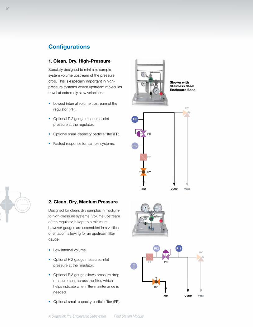
1. Clean, Dry, High-Pressure
Speciallydesignedtominimizesample
systemvolumeupstreamofthepressure
drop.Thisisespeciallyimportantinhigh-
pressuresystemswhereupstreammolecules
travelatextremelyslowvelocities.
• Lowestinternalvolumeupstreamofthe
regulator(PR).
• OptionalPI2gaugemeasuresinlet
pressureattheregulator.
• Optionalsmall-capacityparticlefilter(FP).
• Fastestresponseforsamplesystems.
PR
FP
BV
PI2
PI1
RV
Inlet Outlet Vent
Shown with Stainless Steel Enclosure Base
2. Clean, Dry, Medium Pressure
Designedforclean,drysamplesinmedium-
tohigh-pressuresystems.Volumeupstream
oftheregulatoriskepttoaminimum,
howevergaugesareassembledinavertical
orientation,allowingforanupstreamfilter
gauge.
• Lowinternalvolume.
• OptionalPI2gaugemeasuresinlet
pressureattheregulator.
• OptionalPI3gaugeallowspressuredrop
measurementacrossthefilter,which
helpsindicatewhenfiltermaintenanceis
needed.
• Optionalsmall-capacityparticlefilter(FP).
PR
BV
PI3
PI2 PI1
FP
RV
Inlet Outlet Vent
Configurations

A Swagelok Pre-Engineered Subsystem Field Station Module
11
Configurations
4. High Particulate Load
Handleshighestparticulateloadofany
configuration.
• OptionalPI3gaugeallowspressuredrop
measurementacrossthefilter,which
helpsindicatewhenfiltermaintenanceis
needed.
• Includeslarge-capacityparticlefilter(FP).
• OptionalPI2gaugemeasuresinlet
pressureattheregulator. PR
BV
PI2
PI3
PI1
FP
RV
Inlet Outlet Vent
3. Low Moisture and Particulate Load
Designedforprocesslineswithlowlevelsof
moistureandparticulateload.
• Lowinternalvolumemaintainedinthis
design.
• Membraneseparator(FM)withintegral
gravitydrainallowsmoisturetodropback
toprocess.
• Maximumrecommendedflowratethrough
membraneseparatoris0.18stdft3/min
(5.1stdL/min).
• OptionalPI2gaugemeasuresinlet
pressureattheregulator.
PR
BV
PI2 PI1
FM
RV
Inlet Outlet Vent
A Swagelok Pre-Engineered Subsystem Field Station Module
12
Configurations
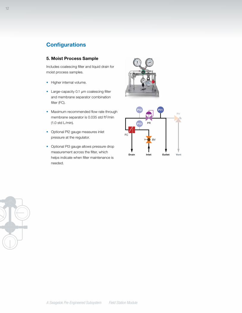
5. Moist Process Sample
Includescoalescingfilterandliquiddrainfor
moistprocesssamples.
• Higherinternalvolume.
• Large-capacity0.1µmcoalescingfilter
andmembraneseparatorcombination
filter(FC).
• Maximumrecommendedflowratethrough
membraneseparatoris0.035stdft3/min
(1.0 std L/min).
• OptionalPI2gaugemeasuresinlet
pressureattheregulator.
• OptionalPI3gaugeallowspressuredrop
measurementacrossthefilter,which
helpsindicatewhenfiltermaintenanceis
needed.
PR
BV
PI2
PI3
PI1
FC
RV
Inlet OutletDrain Vent

A Swagelok Pre-Engineered Subsystem Field Station Module
13
Technical Data
FSM Configuration
Working Pressurepsig (bar)
Temperature Rating, °F (°C)Maximum Air Flow
std ft3/min (std L/min) Filter Internal Volume
in.3 (cm3)With Relief
ValveWithout
Relief Valve
15 psig (1.0 bar) Outlet
Pressure
30 psig (2.1 bar) Outlet
Pressure
1Clean,dry,high-pressure
2500(172) 250(121) 300(148) 0.23(6.5) 0.39(11.0) 0.30(4.9)
2Clean,dry,medium-pressure
2500(172) 250(121) 300(148) 0.23(6.5) 0.39(11.0) 0.30(4.9)
3Lowmoistureandparticulateload
1000(68.9) 185(85) 185(85) 0.18(5.1) 0.18(5.1) 0.56(9.1)
4Highparticulateload
1000(68.9) 250(121) 300(148) 0.23(6.5) 0.39(11.0) 3.05(50.0)
5Moistprocesssample
1000(68.9) 185(85) 185(85) 0.035(1.0) 0.035(1.0) 3.05(50.0)
Forsystemsoutsidetheseparameters,contactyourauthorizedSwageloksalesandservicerepresentative.
TestingEverySwagelokFSMsubsystemisshell
testedwithnitrogenat145psig(10bar)toa
requirementofnodetectableleakagewitha
liquidleakdetector.
Cleaning and PackagingAllSwagelokFSMsubsystemsarecleaned
inaccordancewithSwagelokStandard
Cleaning and Packaging (SC-10),MS-06-62.

A Swagelok Pre-Engineered Subsystem Field Station Module
14
DimensionsDimensions,ininches(millimeters),areforreferenceonlyandaresubjecttochange.
Top
D2 (outlet)
Heaterwiring,two0.88(22.3)holes
Optionalinletflangeboltmounting,fourholes
equallyspacedonboltcircle
3.73(94.7)
5.60(142) 15.7
(399)
6.10(155)
4.50(114)
4.50(114)
15.7(399)
5.00(127)
4.42(112)
7.35(187)
Weight
FSM SubsystemWeight lb (kg)
Basicmodule 25(11.3)
Stainlesssteelenclosure 35(15.9)
ABSenclosure 20(9.1)
Fiberglassenclosure 25(11.3)
Heater 10(4.5)
Stainlesssteelsunshade 9.0(4.1)
ABSplasticsunshade 6.5(2.9)
Fiberglasssunshade 8.0(3.6)
End Connections Base Plate Dimensions
in. (mm)
Type Size ASME
Pressure Class
D1, D2 Dia
D3, D4 Dia
Swageloktubefitting
1/4in. —
0.50(12.7)
0.50(12.7)
6mm —
FemaleNPT1/4in. —
1/2in. —
Entryseal➀ 2in. — 2.00(50.8)
Tubestub➁ 1/4in. — 0.50(12.7)
Flange➂
3/4in.
150
1.50(38.1)
600
1500
11/2in.
150
600
1500
➀ Entrysealincludesinletandoutletfittingswithheat-shrinkablesealtoaccommodate0.75to1.6in.(19.0to40.6mm)insulatedtubing.
➁ AllconnectionsonFSMsubsystemswithABSplasticorfiberglassenclosuresare1/4in.tubestubs.
➂ Flangeavailableforinletconnectiononly.
D1 (inlet) D4
(vent)D3
(drain)
A Swagelok Pre-Engineered Subsystem Field Station Module
15
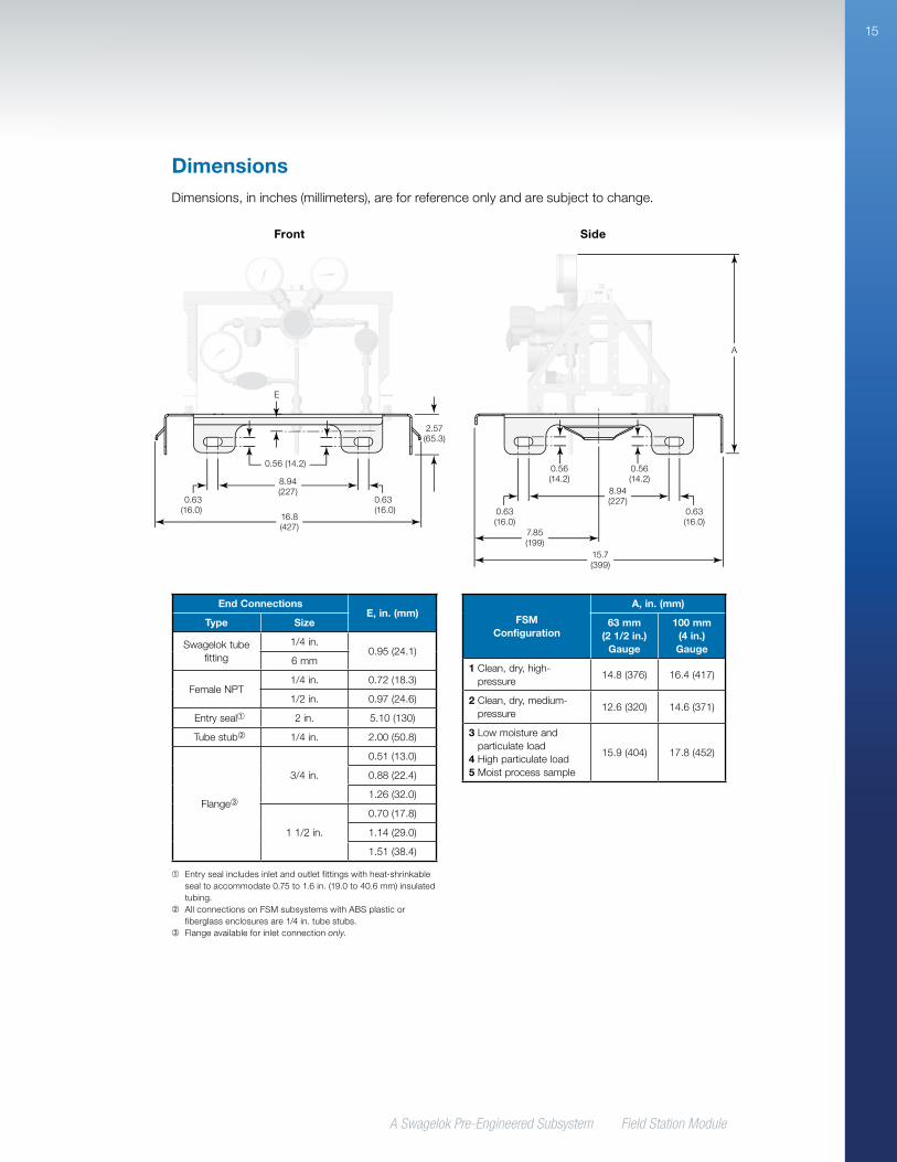
DimensionsDimensions,ininches(millimeters),areforreferenceonlyandaresubjecttochange.
FSM Configuration
A, in. (mm)
63 mm (2 1/2 in.)
Gauge
100 mm (4 in.) Gauge
1Clean,dry,high-pressure
14.8(376) 16.4(417)
2Clean,dry,medium-pressure
12.6(320) 14.6(371)
3Lowmoistureandparticulateload
4Highparticulateload5Moistprocesssample
15.9(404) 17.8(452)
Side
A
15.7(399)
8.94(227)
7.85(199)
0.56(14.2)
0.63(16.0)
0.63(16.0)
0.56(14.2)
End Connections E, in. (mm)
Type Size
Swageloktubefitting
1/4in.0.95(24.1)
6mm
FemaleNPT1/4in. 0.72(18.3)
1/2in. 0.97(24.6)
Entryseal➀ 2in. 5.10(130)
Tubestub➁ 1/4in. 2.00(50.8)
Flange➂
3/4in.
0.51(13.0)
0.88(22.4)
1.26(32.0)
11/2in.
0.70(17.8)
1.14(29.0)
1.51(38.4)
➀ Entrysealincludesinletandoutletfittingswithheat-shrinkablesealtoaccommodate0.75to1.6in.(19.0to40.6mm)insulatedtubing.
➁ AllconnectionsonFSMsubsystemswithABSplasticorfiberglassenclosuresare1/4in.tubestubs.
➂ Flangeavailableforinletconnectiononly.
Front
16.8(427)
8.94(227)
2.57(65.3)
0.56(14.2)
0.63(16.0)
0.63(16.0)
E
A Swagelok Pre-Engineered Subsystem Field Station Module
16
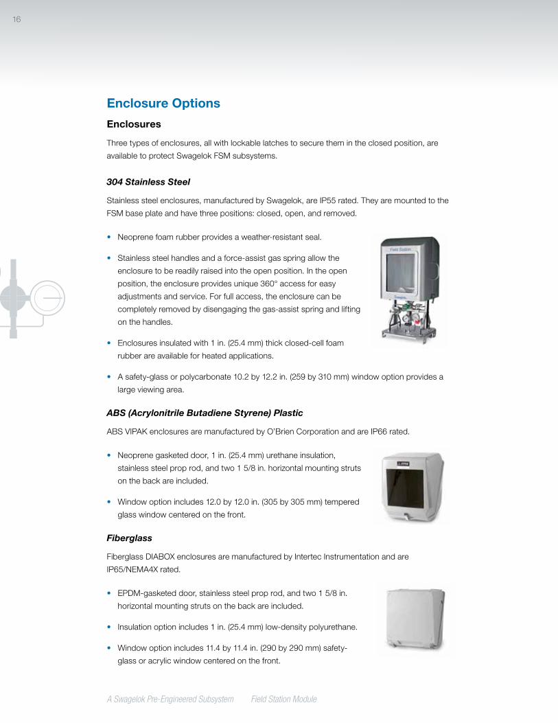
Enclosures
Threetypesofenclosures,allwithlockablelatchestosecurethemintheclosedposition,are
availabletoprotectSwagelokFSMsubsystems.
304 Stainless Steel
Stainlesssteelenclosures,manufacturedbySwagelok,areIP55rated.Theyaremountedtothe
FSMbaseplateandhavethreepositions:closed,open,andremoved.
• Neoprenefoamrubberprovidesaweather-resistantseal.
• Stainlesssteelhandlesandaforce-assistgasspringallowthe
enclosuretobereadilyraisedintotheopenposition.Intheopen
position,theenclosureprovidesunique360°accessforeasy
adjustmentsandservice.Forfullaccess,theenclosurecanbe
completelyremovedbydisengagingthegas-assistspringandlifting
onthehandles.
• Enclosuresinsulatedwith1in.(25.4mm)thickclosed-cellfoam
rubberareavailableforheatedapplications.
• Asafety-glassorpolycarbonate10.2by12.2in.(259by310mm)windowoptionprovidesa
largeviewingarea.
ABS (Acrylonitrile Butadiene Styrene) Plastic
ABSVIPAKenclosuresaremanufacturedbyO’BrienCorporationandareIP66rated.
• Neoprenegasketeddoor,1in.(25.4mm)urethaneinsulation,
stainlesssteelproprod,andtwo15/8in.horizontalmountingstruts
onthebackareincluded.
• Windowoptionincludes12.0by12.0in.(305by305mm)tempered
glasswindowcenteredonthefront.
Fiberglass
FiberglassDIABOXenclosuresaremanufacturedbyIntertecInstrumentationandare
IP65/NEMA4Xrated.
• EPDM-gasketeddoor,stainlesssteelproprod,andtwo15/8in.
horizontalmountingstrutsonthebackareincluded.
• Insulationoptionincludes1in.(25.4mm)low-densitypolyurethane.
• Windowoptionincludes11.4by11.4in.(290by290mm)safety-
glassoracrylicwindowcenteredonthefront.
Enclosure Options
17
A Swagelok Pre-Engineered Subsystem Field Station Module
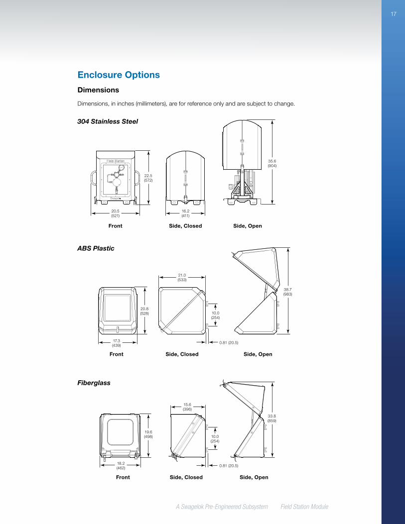
Enclosure Options
Dimensions
Dimensions,ininches(millimeters),areforreferenceonlyandaresubjecttochange.
Fiberglass
304 Stainless Steel
ABS Plastic
Front Side, Closed Side, Open
R
R
20.5(521)
22.5(572)
16.2(411)
35.6(904)
17.3(439)
20.8(528)
21.0(533)
38.7(983)
Front Side, Closed Side, Open
10.0(254)
0.81(20.5)
18.2(462)
19.6(498)
15.6(396)
33.8(859)
Front Side, Closed Side, Open
10.0(254)
0.81(20.5)

A Swagelok Pre-Engineered Subsystem Field Station Module
18
Enclosure Options
Sun Shades
Asanalternativetoenclosures,sunshadesareavailablein
304stainlesssteel,ABSplastic,andfiberglass.
• Stainlesssteelsunshadesaremanufacturedby
Swagelok.
• ABSplasticsunshadesaremanufacturedbyO’Brien
Corporation.
• FiberglasssunshadesaremanufacturedbyIntertec
Instrumentation.
Material Dimensions, in. (mm) Mounting
304SSMounted:
22.4H,20W,20D(569H,508W,508D)
MountstotheFSMbraceinplaceofanenclosure
ABSplasticUnmounted:
19.5H,17W,19.5D(495H,432W,495D)
Mounttoa2in.structuralpipe(notsupplied);twopipeclampsand
mountinghardwareprovidedFiberglassUnmounted:
7.0H,22.4W,22.4D(178H,569W,569D)
ABS Plastic Sun Shade Shown with Mounting Bracket
(Available Separately)
Fiberglass Sun ShadeShown with
Mounting Bracket (Available Separately)
Stainless Steel Sun Shade

A Swagelok Pre-Engineered Subsystem Field Station Module
19
HeatersandthermostatsforSwagelokFSM
subsystemsaremanufacturedbyIntertec
Instrumentation.
Enclosure Heaters
Heatersareavailableforapplicationswhere
environmentaltemperaturesmaydrop
belowthedewpointofthegas.Heaters
aremountedinsidetheenclosureforfreeze
protectionortemperaturemaintenance.An
insulatedenclosureshouldbeorderedwitha
heatertomaximizeeffectiveness.
Enclosureheaterswiththermostatsare
availablewithATEX/IECorCSA/UL
approvals.
Enclosure Heater Selection
Enclosureheaterstypicallyareselectedbasedonthetemperaturedifferential(T ) betweenthe
setthermostattemperatureandthelowestexpectedambienttemperature.
Enclosure Configuration
Maximum T, °F (°C)
50 (28) 75 (42) 100 (56) 125 (69) 150 (83)
Heater Wattage Required
Stainless Steel Enclosure
Insulated,nowindow 100W 100W 100W 200W —
Insulated,withwindow 100W 100W 200W 200W —
ABS and Fiberglass Enclosures
Insulated,nowindow 50/100W 50/100W 100W 100W 200W
Insulated,withwindow 50/100W 100W 100W 200W 200W
Uninsulated,nowindow➀ 100W 200W — — —
Uninsulated,withwindow➀ 100W 200W — — —
➀ Availableinfiberglassonly.
Heating Options
Enclosure Heater with Thermostat
(ATEX/IEC Approval)
Enclosure Heater with Thermostat
(CSA/UL Approval)

A Swagelok Pre-Engineered Subsystem Field Station Module
20
Regulator Heaters
Regulatorheatersareintendedfor
applicationswheretheJoule-Thomsoneffect
fromhighpressuredropsmaycausethe
regulatortofreezeorthegastocondense.
Regulatorheatersaremountedtothebottom
ofthepressureregulatorbodytoheatthe
regulatorbodyandsurroundingair.
Regulatorheatersareself-limitingandareavailablewithATEX/IECorCSA/ULapprovals.
Heater Thermostats
Heaterthermostatsprovidetemperature
controloftheenvironmentwithinthe
enclosureandareavailablewithATEX/IEC
andCSA/ULapprovals.
Enclosureheaterthermostatsareavailable
at50,86,and125°F(10,30,and50°C)set
temperatures.Regulatorheatersareselflimiting.
Heater ControlPower
W
Set Temperature
°F (°C)
Enclosure Thermostat
100
50(10)
86(30)
125(50)
20050(10)
86(30)
Regulator Self-limiting 50T4max
(275°F[135°C])
Regulator Heater
Heating Options

A Swagelok Pre-Engineered Subsystem Field Station Module
21
Ordering InformationBuildanFSMsubsystemorderingnumberbycombiningthedesignatorsinthesequenceshownbelow.
FSM- 1 -RB 1 A B -S4 S4 SA - XXX 52 41 3 5 6 7 8 9 10
1 Configuration 1 =Clean,dry,high-pressure
(page 10) 2 =Clean,dry,medium-pressure
(page 10) 3 =Lowmoistureandparticulateload
(page 11) 4 =Highparticulateload(page11) 5 =Moistprocesssample(page12)
2 Maximum Inlet Pressure
Outlet pressure control range is 0 to 50 psig (0 to 3.4 bar) for all models.
F =100psig(6.8bar) J =300psig(20.6bar) L =1000psig(68.9bar) R =2500psig(172bar)➀
➀Availableonconfigurations1and2 only.
3 Pressure Gauge Location(s)
Swagelok B Model
A =Regulatoroutletonly B =Regulatorinletandoutlet C =Filterinletandregulatoroutlet➀ D =Filterinlet,regulatorinlet,and
regulatoroutlet➀
➀ Availableonconfigurations2, 4and5 only.
8 Outlet, Drain, Vent Connections
Bulkhead (304SSenclosureonly)
S4 =1/4in.Swageloktubefitting 6M =6mmSwageloktubefitting F4 =1/4in.femaleNPT
Tube
ES =Entrysealoutlet(includesremovable1/4 in.tubestub);removable1/4 in.tubestubdrainandvent)
T4 =1/4in.tubestub(removable)
9 Enclosure (page16) / Sun Shade (page18)
XX =Noenclosure,nosunshade
304 Stainless Steel Enclosure
SA =Uninsulated,nowindow SB =Uninsulated,safetyglasswindow SC =Uninsulated,polycarbonatewindow SE =Insulated,nowindow SF =Insulated,safetyglasswindow SG =Insulated,polycarbonatewindow
ABS Plastic Enclosure
AE =Insulated,nowindow AF =Insulated,safetyglasswindow
Fiberglass Enclosure
GA =Uninsulated,nowindow GB =Uninsulated,safetyglasswindow GD =Uninsulated,acrylicwindow GE =Insulated,nowindow GF =Insulated,safetyglasswindow GH =Insulated,acrylicwindow
Sun Shade
AS =ABSplastic GS =Fiberglass SS =304stainlesssteel
10 Heater (page 19)/Thermostat (page 20)
XXX =Noheater,nothermostat
Approval➀➁➂ Thermostat
Enclosure Heater, 100 W (convection heater, T3)
1A1 =ATEX/IEC230V 50°F(10°C) 1A3 =ATEX/IEC230V 86°F(30°C) 1A5 =ATEX/IEC230V 122°F(50°C) 1C1 =CSA/ULD1120V 50°F(10°C) 1C3 =CSA/ULD1120V 86°F(30°C) 1C5 =CSA/ULD1120V 122°F(50°C) 1D1 =CSA/ULD1230V 50°F(10°C) 1D3 =CSA/ULD1230V 86°F(30°C) 1D5 =CSA/ULD1230V 122°F(50°C)
Enclosure Heater, 200 W (convection heater, T3)
2A1 =ATEX/IEC230V 50°F(10°C) 2A3 =ATEX/IEC230V 86°F(30°C) 2C1 =CSA/ULD1120V 50°F(10°C) 2C3 =CSA/ULD1120V 86°F(30°C) 2D1 =CSA/ULD1230V 50°F(10°C) 2D3 =CSA/ULD1230V 86°F(30°C)
Regulator Heater, 50 W (conduction heater, self-limiting, T4, 110 to 265 V range for most applications)
5BX =ATEX/IEC265V None 5EX =CSA/ULD2265V None➀ Heaterandthermostatapprovals:
ATEX/IEC230V—II2G/DEExdIIC,(230V)ATEX/IEC265V—II2G/DEExdIIC,(110to265V)CSA/ULD1120V—ClI;Div1;A,B,C,D(120V)CSA/ULD1230V—ClI;Div1;A,B,C,D(230V)CSA/ULD2265V—ClI;Div2;A,B,C,D(110to
265V)➁ IncludedATEXjunctionboxisII2GEExeIIT6
rated.➂ IncludedCSA/ULjunctionboxissuitableforgas
groupsA,B,andConly.)
11 Additional Options
For multiple options, add numerical, then alphabetical designators.
5 =Swagelokbimetalthermometer,0to200°F(–15to90°C),3in.(76 mmdialsize)
K =SWAK®threadsealantonNPTthreads(PTFEtapeisstandard)
5 Filter A =15µmTFseriesparticlefilter
(configurations1and2only) X =Noseparatefilter,25µmgauze
inletfilteronregulator Y =Requiredforconfigurations3, 4,
and5
4 Pressure Gauge Dial Size, Fill
Swagelok B Model
1 =63mm(21/2in.),unfilled 2 =63mm(21/2in.),siliconefill 3 =100mm(4in.),unfilled➀
4 =100mm(4in.),siliconefill➀
➀ Filterinletgaugehasa63 mm(2 1/2in.)dial.
6 Relief Valve A =Pre-set➀adjustablereliefvalve B =Pre-set➀adjustablereliefvalve,
manualoverridehandle X =Noreliefvalve
➀ For100and300psig(6.8and20.6bar)systems,RL3reliefvalveisfactorysetto45 psig(3.1 bar);for1000and2500psig(68.9and172 bar)systems,R3Areliefvalveisfactorysetto50 psig(3.4bar).
7 Inlet Connection
Bulkhead
S4 =1/4in.Swageloktubefitting 6M =6mmSwageloktubefitting F4 =1/4in.femaleNPT F8 =1/2in.femaleNPT
Tube
ES =Entryseal(includesremovable1/4 in.tubestub)
T4 =1/4in.tubestub(removable)
Flange (NotavailableonABSplasticandfiberglassenclosures)
B1 =3/4in.,ASMEclass150➀
B3 =3/4in.,ASMEclass600➁
B5 =3/4in.,ASMEclass1500 D1 =11/2in.,ASMEclass150➀
D3 =11/2in.,ASMEclass600➁
D5 =11/2in.,ASMEclass1500➀ Limitspressureto275psig(18.9bar).➁ Limitsconfigurations1and2to1440psig
(99.2 bar).
11

A Swagelok Pre-Engineered Subsystem Field Station Module
22
Mounting Brackets
Avarietyofbrackets—includingback-center,
cantilever,direct,andwallmountingmodels—
isavailable.
Materials
Component Material
Splitwashers,washers,hexbolts,struts,mountingplate,roundedU-bolts,
squaredU-bolts
300seriesSS
Strutnuts Electrogalvanizedsteel
Dimensions
Dimensions,ininches(millimeters),areforreferenceonlyandaresubjecttochange.
Back-Center (BC) Mounting Bracket Kits
Cantilever (C, CS, CL) Mounting Bracket Kits
Thesekitsareavailableincenterline,short,andlongcantilevermodels.
FSM with Back-Center Mounting Bracket
15.4(391)
17.6(447) 7.00
(178)
16.8(427)
Front SideTop
CL:33.6(853)
9.95(253)max
22.6(574)max
7.00(178)
6.10(155)
CS:22.0(559)
C:15.7(399)
SideTopCLdesignateslongcantilever;CSdesignatesshortcantilever;Cdesignatescenterlinecantilever.
Accessories

A Swagelok Pre-Engineered Subsystem Field Station Module
23
Direct (DM) Mounting Bracket Kits
Wall (WM) Mounting Bracket Kits
15.7(399)
7.00(178)
13.7(348)
18.9(480)
Front SideTop
10.8(274)16.5
(419)
15.0(381)
19.7(500)
Front SideTop
Accessories
Ordering Information
BuildanFSMmountingbracketkitorderingnumberbycombiningthedesignatorsinthe
sequenceshownbelow.
FSM-MK-BP - CS - 32P21 3
1 System Type BP =Baseplate PE =Plasticenclosure(available
withback-centermountingstyleBConly)
2 Mounting Style BC =Back-center(availablefor
supporttype32Ponly) C =Center-linecantilever CL =Longcantilever CS =Shortcantilever DM =Direct WM =Wall(doesnotrequire
supporttypedesignator)
3 Support Type
Omit designator for wall mount (WM) mounting style.
32P =2in.pipe 32S =2in.squaretube 26S =1 5/8in.strut.

Swagelok,SWAK—TMSwagelokCompanyAvenger,Genie,MembraneSeparators—TMA+Manufacturing,LLC;VIPAK—TMO’BrienCorporation;DIABOX—TMIntertec©2012–2013SwagelokCompany,PrintedinU.S.A.,AGS,January2013,R3,MS-02-359
Safe Product SelectionWhen selecting a product, the total system design must be considered to ensure safe, trouble-free performance. Function, material compatibility, adequate ratings, proper installation, operation, and maintenance are the responsibilities of the system designer and user.
Caution: Do not mix or interchange Swagelok product components with those of other manufacturers.
Warranty InformationSwagelokproductsarebackedbyTheSwagelokLimited
LifetimeWarranty.Foracopy,visitswagelok.comorcontact
yourauthorizedSwagelokrepresentative.
Regulatory Compliance
Europe
• PressureEquipmentDirective(PED)97/23/EC
• AtmospheresExplosiveDirective(ATEX)94/9/EC
• RestrictionofHazardousSubstancesDirective(RoHS)2002/95/EC
Americas
• Hazardouslocationelectricalapproval(CSA/UL)
• CRNregisteredinCanada(individualcomponentsofassembly)
ContactyourauthorizedSwagelokrepresentativeforspecificassemblycomplianceapprovals
andcertificationsavailablefromthemanufacturer.
Replacement Filter Element Kits
Kitsincludefilterelementandinstructions.
FSM Configuration Kit Ordering Number
1Clean,dry,high-pressure
SS-4F-K4-152Clean,dry,medium-pressure
3Lowmoistureandparticulateload
FSM3-FILTER-K
4Highparticulateload FSM4-FILTER-K
5Moistprocesssample FSM5-FILTER-K
Accessories