Embed Size (px)
Citation preview

FieldQApril 2017
Installation guideDOC.IG.QC54.1 Rev.: 2
FieldQ
FieldQ Control Module QC54 FOUNDATION™ Fieldbus

2
FieldQApril 2017
Installation guideDOC.IG.QC54.1 Rev.: 2
Fig. 2.1 Check proper mounting before connecting air supply and electrical wiring.
OK
OK
Control Module Type Label =
QC54..WP.. = Foundation Fieldbus™ Weather Proof
QC54..P4..= Foundation Fieldbus™ Non-incendive/Non Sparking/FISCO ic
QC54..P1..= Foundation Fieldbus™ intrinsically safe/FISCO
Actuator Type Label = QS xxxx = Single acting (Spring Return)
QD xxxx = Double acting
Fig. 2.2 Identification
2
1
1 Applicable modules
QC54 - FOUNDATION Fieldbus™
- Weather Proof
- Non-incendive/Non-Sparking/FISCO ic
- Intrinsically safe/FISCO
Note:
These variations can be equipped with one or two pilot valves:
* One pilot valve is default and suitable for normal operation of double acting or spring return actuators.
* Two pilot valves are required for Fail in Last Posi-tion function on double acting actuators.
The enclosures have a IP66 or NEMA 4X, ingress protected rating.
2 Before starting
* Actuator must be isolated both pneumatically and electrically before any (dis)assembly is begun.* Hazards related to the control of external processes under measurement, are beyond the scope of of the content described in this document.* Installation, adjustment, putting into service, use, assembly, disassembly and maintenance of the control module must be done by qualified personnel.* Do not install, operate, or maintain a Q series control module without being fully trained and qualified in valve, actuator, and accessory installation, operation, and maintenance.* To avoid personal injury or property damage, it is important to carefully read, understand, and follow all of the contents of this manual, including all safety cautions and warnings.* Be sure that the actuator is correctly mounted before connecting air supply and electrical wiring (see Installation & Operation Manual FieldQ Valve Actuator, DOC.IOM.Q.E)* Check the module label for the right execution (see figure 2.2)* Check the type of actuator: single or double acting (see figure 2.2).* For mechanical installation of the module see installation instruction leaflet DOC.QC4.MTI.1, as shipped with the module.* If you have any questions regarding these instructions, contact your Emerson sales office before proceeding as shipped with the module.

3
FieldQApril 2017
Installation guideDOC.IG.QC54.1 Rev.: 2
Control Module Type Label
Terminal com-partment
Lockable Module cover
Option: 1 or 2 speed control throttles
Fig 2.4 Control module overview
Option: Local Manual ControlOption: Additional Local Manual Control for “Fail in Last Position”
2.1 Mechanical alignment and mounting of the control module
The control module is equipped with an alignment-edge on top of the module. This allows easy align-ment and mounting of the control module on to the actuator housing.
Procedure: (see figure 2.3)
1. First take care that both mating faces from the actuator and control module are clean and free of dirt.
2. Check if the module has the required function3. Remove the transparent film from the control
module. 4. Ensure seals are placed correctly.5. Level the screws with the surface.6. Place the alignment-edge (1) of the control
module at the top of the pneumatic interface.7. Flip the module down taking care that the IPT
Probe (2) on the actuator fits in the mating hole on the control module and loosely place the screws.
8. Tighten screws according force in sequence.
Alignment-edge
Alignment-edge
Fig. 2.3 Alignment and mounting of control module to actuator
IPT probe
Tightening moments
The Control Module should be fastened by using an Allen key and applying the following tightening moments:
- Allen Key No 5: 6.1 to 6.6 Nm (54 - 58.4 In.lbs)
(1)
(2)

4
FieldQApril 2017
Installation guideDOC.IG.QC54.1 Rev.: 2
3 Pneumatic connections
Fig 3.2 Install drip loops
5µm
OK
IMPORTANT
1 The actuator/valve combination can move after connecting the air supply.
2 Ensure that the QC54 control modules are mounted properly to the actuator to achieve good functioning and the required ingress protection, before connecting the air supply.
3 Check that the maximum supply pressure Pmax = 8bar/116Psi
4 Be sure that the minimum required supply pressure for the application is available at the actuator.
5 Take appropriate measures to prevent conden-sation or moisture to entering the actuator or the control module. Condensation or moisture can damage these components and can result in failures.
6 The exhaust ports Ra and Rb on the module (see figure 3.1) are shipped from the factory with transport protection.
* If ingress protection IP66 or NEMA 4X is re-quired, appropriate connections must be used in exhaust ports Ra & Rb.
3.1 Operating media :* Air or inert gasses. * Air filtered at 5 micron.* Dew point 10 K below operating temperature.* For subzero applications take appropriate
measures.
3.2 Single acting (spring return) or Double acting actuator :
1 Remove the transport sticker from the air supply (Ps).
2 Connect air supply to port (Ps).
Fig. 3.1: Pneumatic connections
Single acting
Control
Module cover
Ps
1/4” BSP or 1/4” NPT
Double acting
Ps
1/4” BSP or 1/4” NPT
Ra
Ra
Rb

5
FieldQApril 2017
Installation guideDOC.IG.QC54.1 Rev.: 2
4 Electric Connections
WARNING
* Do not put the Control module and the Pneu-matic module in direct contact with magnetic material. This can cause damage or malfunc-tion of the position feedback.
* If the Control Module is used in a manner not specified by the manufacturer, the protection provided by the equipment may be impaired.
* If required, mount earth wire (1) between top (2) and bottom (3) ring of earth wire connec-tion (see figure 4.1).
Table 4.1 Electrical data QC54 - FF
Voltage range * 9 to 32 voltsMaximum current 18 mAReverse polarity protection
Unit is not polarity sensitive.
Required external protection
Restrict the power supply current to <600mA.
Environmental conditions :Temperature * -20°C to +50°C
(-4°F to +122°F)Humidity 0 to 85% at 25°C(+77°F)
derate to 50% above 40°C (104°F) (non-condensing).
Altitude Operating full power available up to 2000 meter (6000 feet).
Use In- and outdoor.
* In case the Control module is used in Hazardous locations, check the chapters 10, 11 or 12 for detailed instructions.
Fig.4.1 Earth wire connections
!

6
FieldQApril 2017
Installation guideDOC.IG.QC54.1 Rev.: 2
12
+
- 3
Blue
Brown
Green/YellowM127/8" UNC
1
2
3
41
2
34
1
2
31
24
Fig. 4.3 Terminal connections
Quick connector pinouts:(male chassis part)
Fig. 4.4 Quick connector pinouts
Quick connector
Terminal
Electrical entries: Button board
4.1 Procedure1. Remove control module cover (see figure 4.2) 2. Guide the cable(s) through the electrical entry(ies). - Use and mount cable glands as required by national or local legislation. - When IP65/NEMA4X ingress protection is required, the electrical entries must be fitted with glands rated IP65/NEMA4X or higher. - Apply minimum thread counts: For NPT, at least 5 full threads For Metric, at least 8 full threads for Group A/B and 5 full threads of Group C/D3. Connect the FOUNDATION™ Fieldbus signal
to the applicable terminals (see figure 4.3). - For 7/8” or M12 quick connector pinout, see figure 4.3 and 4.4. - For hazardous area connections, see the wiring instructions in 11.5 and 11.6 4. Mount the function module cover to the hous-
ing (see figure 4.2) or continue with chapter 5. Take care that the cover seal is in place to comply
to dust and water tightness according to IP66/NEMA4X.
4.2 Foundation Fieldbus installation and wiring guidelines
Please check www.fieldbus.org for various applica-tion guides like installation and wiring guidelines.
Table 4.2 Wiring dimensions
Wire type DimensionsSolid wire 2.5mm2 max.Stranded wire 0.33 - 2.5mm2 or 22 - 12 AWG
Table 4.3 Tools
Tool DimensionsCover lock screw Allen key 2mmTool for terminals Screw driver 0.6 x 3.5
Fig. 4.2 Installing wiring
Field wiring Actuator wiring
FF
Power supply
Wiring Terminals
3/4”NPT
or M20
1/2”NPT
or M20
Control Module Type Label
Terminal compartment
Lockable Module cover

7
FieldQApril 2017
Installation guideDOC.IG.QC54.1 Rev.: 2
5 Initial setup
5.1 Initialization procedureInitialization sets automatically the switch points for the position feedback of the actuator (see fig. 5.2)
Additionally, initialization checks if the actuator and control module configuration match. This procedure will detect the action type (Fail-Open, Fail-Close or Fail in last position) and generate an alert if there is a configuration issue.
This process is done automatically, by the module, however, the user must start it and the unit must be wired according chapter 4. Digital communication is not required but power supply is necessary (9V to 32V DC). The initialization process can be started in one of two ways:
1. Initialization using the local buttons (see §5.2).2. Initialization using a bus command (see
Reference manual QC54, DOC.RM.QC54.E)
5.2 Initialization using local buttons 1 Press and confirm press the “Status/Auto-Initial-
ization” button2 Status LED will blink.3 Actuator will cycle 2 or 3 times.4 At the end of the routine the Status LED switches
to constant on, meaning the initialization was successful.
Remark:
- If the button board does not work, see §5.3.1.- If the Status LED is flashing, the auto initializa-
tion routine has failed, see §5.3.2.- If the read out in the PLC or DCS is reversed or
readjustment of the exact positions is needed, or- If it is not possible to finish the auto-initialization
routine, the limit switch points can be set, by the bus. In both cases, see Reference manual QC54, DOC.RM.QC54.E. chapter 3.4
WARNING
* During the initialization routine the actuator /valve combination will cycle several times.
* Before initialization check whether the actuator and valve have the same “Open” and “Closed” positions.
* Ensure that the valve stroke is not obstructed before the initialization routine is started.
Closed reassignment button
Fig. 5.1 Reassignment buttons
(located behind front cover of module).
Fig. 5.2 Feedback characteristic
Press and
confirm press
* The default setting of the reassignment buttons is: enabled when the unit is in “Out of Service”.
Table 5.1 Status LED indications
Status Status LED actionOK (init successful) Constant onInitializing Blinking (see fig. 5.1)Init error Flashing (see fig. 5.1)Init default Flashing (see fig. 5.1)Identification Flashing for 300 sec.
5.3 Troubleshooting
LED = Flashing
on
off
LED = Blinking
on
off
Status LED
Open reassignment button
Time
10°max
10°max
±40°
±40°
“Close” end position
“Open” end position
End stop offsets
Factory settings
End stop offsets
Setting after initialization
!
8
FieldQApril 2017
Installation guideDOC.IG.QC54.1 Rev.: 2
!
Fig. 5.3 Button board functionality
Closed Reassignment
button
Status / Auto Initialization
button
Open Reassignment button
5.3.1 “Factory default settings”, using the button board.
To set the control module to its factory default set-tings, do the following;
1. Power must be connected according chapter 4 and the Status LED is either on or flashing.
2. Disconnect the power.3. Press both reassignment (OPEN and CLOSE) but-
tons.4. Reconnect power.5. Status LED goes on.6. Release the reassignment (OPEN and CLOSE)
buttons.7. Observe that the Status LED indicates that the
unit is in its “Init Default” state (Flashing, see §5.2)
5.3.2 If auto initialization procedure has failed (Status LED is flashing)
1. Check supply pressure2. Check Actuator assembly code (see Installation
& Operation Manual FieldQ Valve Actuator, DOC.IOM.Q.E)
3. Repeat the initialization procedure.4. When the actuator does not move within 10
seconds, the auto initialization will fail. 5. To solve this either; - Perform the “default setting” procedure (see
§5.3.1) and repeat the initialization proce-dure (see §5.2), or
- Set the limit switch points individually by the bus see Reference manual QC54, DOC.RM.QC54.E chapter 3.4.
6 Check functioning
To perform a function test, please see chapter 3 of Reference manual QC54, DOC.RM.QC54.E.
- After checking the functioning mount the control module cover to the housing (see figure 3.1).
7 MaintenanceThe FieldQ control modules are designed to operate without maintenance.
For any further maintenance to the actuator see Installation & Operation Manual FieldQ Valve Actuator, DOC.IOM.Q.E or contact your local FieldQ representative.
For any further maintenance to the control module see Maintenance Manual, DOC.MM.QC54.E or contact your local FieldQ representative.
Installation, adjustment, putting into service, use, assembly, disassembly, maintenance and repair of the control module must be done by qualified personnel.
WARNING• Substitution of components may impair
suitability of the equipment
Table 2 Button board functionality (see fig. 5.3)
Action Reassignment buttonsInitialize Press and confirm press the “Status/Auto-Initialization” button.Set to factory default Push both reassignment buttons and hold while powering up. Release
buttons when Status LED is solid. Switch point re-adjustment A new switch point can be set by pressing and confirm press the corre-
sponding “Open” or “Closed” button (actuator wil not cycle).

9
FieldQApril 2017
Installation guideDOC.IG.QC54.1 Rev.: 2
8 Optional Controls
8.1 Manual Control options
(see figure 8.1)For commissioning, emergency or maintenance purposes, the FieldQ can be supplied with one or two Manual Control options. These can operate the spool t valve(s) inside the module and as such operate the actuator, when there is air pressure available, but no control signal or power supply.
8.1.1 Mounting Manual Control
1. To add a Manual Control, remove the plug(s) in front of the module and turn in the Manual Control.- For normal operation the module should be
fitted with one Manual Control.
- For Double Acting with a Fail-in-Last-Position function, two Manual Control can be fitted.
8.1.2 Manual Control operation
1. The Manual Control has a “Push & Lock” func-tion:- To operate the Manual Control, use a screw
driver, push to activate and release to de-activate the pilot valves.
- If required turn it 45°, to lock it in position and keep the actuator in its operated state.
2. In case of a Fail in Last Position configuration with two manual controls:- The manual control on the right side (default
location) will pressurize the central air cham-ber and cause the actuator to rotate counter clock wise. For reverse acting FieldQ actuators (Assembly code CC) the actuator will rotate clock wise.
- The manual control on the left side (Location for 2nd Manual Control) will pressurize the end cap air chambers and cause the actuator to rotate clock wise. For reverse acting FieldQ actuators (Assembly code CC) the actuator will rotate counter clock wise.
- In order to operate one of the manual con-trol, be sure the opposite manual control is de-activated and unlocked.
45°
Fig. 8.1 Local Manual Control options
Location for 2nd Manual Control
Default location of Manual Control
On
Off

10
FieldQApril 2017
Installation guideDOC.IG.QC54.1 Rev.: 2
8.2 Speed control option
(see figure 8.2).The FieldQ can be supplied with a Speed Control option. One throttle is required for Spring Return actuators and up to two for Double Acting actua-tors.
The speed control throttle controls the air flow in and out of an air chamber and as such limits the speed of the “Opening” and “Closing” stroke simultaneously
8.2.1 Mounting Speed Control throttle(s):
1. Remove the plug(s) at the side of the module and turn in the throttle (2).
2. Spring Return actuators: Use the top entry only.3. Double acting actuators: Use both bottom and
top entries. - For standard actuators, the top entry will
throttle the closing stroke.
- For standard actuators, the bottom entry will throttle the opening stroke.
- For reverse acting actuators, the opposite strokes will be throttled.
8.2.2 Adjusting Speed Control throttle(s):
1. Remove the nut cap (1).2. Clockwise rotation of the adjustment screw
reduces the speed.3. Counter clockwise rotation of the adjustment
screw increases the speed.4. Replace the nut cap.
9 Related Information
2 1
Spring Return: Top entry only.
Fig. 8.2 Speed control operation
Double Acting: Bottom and/or top entries.
9.1 FOUNDATION Fieldbus installation and wiring guidelines
Please check www.fieldbus.org for various applica-tion guides like installation and wiring guidelines.
9.2 Other Related InformationOther documents containing information related to the FieldQ module include:
1.604.12 FOUNDATION Fieldbus Control Module data sheet
DOC.RM.QC54.E Reference Manual for FieldQ with FOUNDATION Fieldbus Function module.
DOC.IOM.Q.E Installation Operation & Mainte-nance Manual.
These documents are available, in multiple languages, for download from
www.emerson.com/fieldq
9.3 Device driverThe following DD drivers can be downloaded from www.emerson.com/fieldq:
For general use Q-Series DD Rev. 4For use in combina-tion with DeltaV
Q-Series DD Rev. 4 DeltaV
9.4 Applied IECEx standardsThe following standards are applied:
- For FieldQ Control Module QC54...P4... ,IEC 60079-0 Ed. 6.0 : 2011
IEC 60079-15 Ed. 4.0 : 2010
IEC 60079-31 Ed. 2.0 : 2013
- For FieldQ Control Module QC54...P1... ,IEC 60079-0 Ed. 6.0 : 2011
IEC 60079-11 Ed. 6.0 : 2011
IEC 60079-26 Ed. 3.0 : 2014

11
FieldQApril 2017
Installation guideDOC.IG.QC54.1 Rev.: 2
EU Declaration of Conformity
____________________________ S. Ooi Vice President, Global Marketing & Pneumatic/Hydraulic SBU Emerson, Actuation Technologies
2016-11-25 Houston TX, U.S.A.
FieldQ
ROC nr 8440Rev. 2
Signed:Name:Position:
Date:Place:
Legal representative entity for the European Union:
Emerson Process Management, Valve AutomationAsveldweg 11, 7556 BR Hengelo Netherlands
EU DECLARATION OF CONFORMITYIssued in accordance with the
EMC Directive 2014/30/EU, Appendix 1 ATEX Directive 2014/34/EU
We hereby declare, that the products specified below meet the basic health and safety requirements of the above mentioned European Directives.
Product description: QC54 Foundation Fieldbus Control moduleSerial number: Each Control module has an identifiable serial numberYear of Construction: Each Control module has an identifiable Year of ConstructionManufacturer: Emerson Machinery Equipment (Shenzhen) Co. Ltd. Bao Heng Technology Industry Park Phase 2, North Hong Lang 2nd Road District 68, Bao’an District, 518101 Shenzhen, China
EMC Directive 2014/30/EUTypes: QC54...Applicable standards: IEC61326-1 : 2012 NAMUR Recommendations : NE21: 2004
ATEX Directive 2014/34/EUTypes: QC54...P4... ATEX Certificate No.: Dekra 16ATEX0006 X Marking: II 3 G Ex nA IIC T4 Gc Ta = -20°C ... +50°C II 2 D Ex tb IIIC T80°C DbApplicable standards: EN 60079-0 : 2012 + A11 EN 60079-15 : 2010 EN 60079-31 : 2014
Types: QC54...P1...ATEX Certificate No.: DEKRA 16ATEX0006 X Marking: II 2 G Ex ia IIC T4 Ga II 2 D Ex ia IIIC T80°C Da Ta = -20°C ... +50°CApplicable standards: EN 60079-0 : 2012 + A11 EN 60079-11 : 2012 Notified body: DEKRA Certification B.V., Notified body no : 0344 Meander 1051, 6825 MJ Arnhem, The Netherlands
EN

12
FieldQApril 2017
Installation guideDOC.IG.QC54.1 Rev.: 2
!
10 Installation instructions for Non Incendive or Non sparking
Fig 1. Product marking
IECEx Hazardous or Classified Location
Certificate : IECEx DEK 16.0006XNon sparkingEx nA IIC T4 GcEx tb IIIC T80°C Db
ATEX Hazardous or Classified Location
Certificate : DEKRA 16ATEX0006 XNon sparking
II 3 G Ex nA IIC T4 Gc II 2D Ex tb IIIC T80°C Db
Hazardous or Classified Location
- Non Incendive, Class I, II, III, Division 2, Groups ABCDEFG, T4,
- Class 1, Zone 2 Group IIC T4
RoHS Directive This product is only intended for use in large scale fixed installation excluded from the scope of Directive 2011/65/EU on the restriction of the use of certain hazardous substances in electrical and electronic equipment (RoHS 2).
Ambient temperature:
T4 @ Ta = -20°C...+50°C IP66/Nema 4X
10.2 ATEX/IECEx Intended use• The Control Module QC54..P4.. of the
FieldQ pneumatic actuator is a Group II category 3 equipment with protection level Gc (IECEx).
• The pneumatic actuator part, together with the pneumatic module part of the FieldQ pneumatic actuators is a Group II category 2 equipment.
• Both are intended for use in areas in which explosive atmospheres caused by mixtures of air and gases, vapours, mists or by air/dusts are likely to occur.
• Therefore the assembly may be used in hazard-ous area classified Zones 2 (Gasses) and/or 21, 22 (Dust).
10.3 Safety instructions
WARNING• Personal injury or property damage caused
by fire or explosion may occur if the module is opened in any area which contains a potentially explosive atmosphere or has been classified as hazardous.
• Do not open when module is energized.
• Prevent any kind ignition during installation, adjustment, putting into service and use.
• Assembly, disassembly and maintenance must be done in safe area’s without a poten-tial explosion hazard.
• Installation, adjustment, putting into service, use, assembly, disassembly and mainte nance of the pneumatic actuator must be done by qualified personnel.
• Provisions must be made to prevent the rated supply voltage being exceeded by more than 40%.
• Potential electrostatic charging hazard, clean only with a damp cloth - danger of propagat-ing discharge.
• The apparatus shall be installed in such a way that the risk from electrostatic discharges and propagating brush discharges caused by rapid flow of dust is avoided.
• Precaution shall be taken to avoid danger of ignition due to electrostatic charges on the marking plate of the enclosure.
• Substitution of electronics cartridge, switch cartridge, pilot valve cartridge, pneumatic cartridge, enclosure and seals must be with parts from Emerson else the suitability for Division 2 will be impaired.
Table 10.1 Wiring dimensions
Wire type DimensionsSolid wire 2.5mm2 max.Stranded wire 0.33 - 2.5mm2 or 22 - 12 AWG
10.1 Product marking
Control Module Type Label
Terminal compartment
Lockable Module cover
Do not open when an explosive atmosphere may be present

13
FieldQApril 2017
Installation guideDOC.IG.QC54.1 Rev.: 2
10.4 Wiring instructions QC54 Non Incendive / Non Sparking Control Modules
Unclassified or Non Hazardous Location
Hazardous or Classified Location
FF
Power supply
Warning
* Explosion hazard. Do not disconnect equipment when a flammable or combustible atmosphere is present.
* Use installation wiring connections with admitted maximum operating temperature of at least 20 ºC (68°F) higher than maximum ambient.
Electrical Input:Voltage level: 9 to 30 voltsCurrent 18 mA maximumCable range:Solid wire 2.5mm2 maxStranded wire 0.33 - 2.5mm2 or 22 - 12 AWGProtection:Reverse polarity Unit is not polarity sensitive.Required external Protection
Restrict the power supply cur-rent to <600mA.
* The current restricted power supply meets NEC Class 2, as described by the National Electrical Code® (ANSI/NFPA 70 (NEC®))

14
FieldQApril 2017
Installation guideDOC.IG.QC54.1 Rev.: 2
11 Intrinsically safe installation instructions
11.1 Product marking
Fig 1. Product marking
IECEx Hazardous or Classified Location
Certificate : IECEx DEK 16.0006X- Intrinsically safe
Ex ia IIC T4 Ga Ex ia IIIC T80°C Da
ATEX Hazardous or Classified Location
Certificate : DEKRA 16ATEX0006 X- Intrinsically safe
II 2 G Ex ia IIC T4 Ga II 2 D Ex ia IIIC T80°C Da
Hazardous or Classified Location
- Intrinsically safe, Class I, II, III Div.1, Groups ABCDEFG, T4
- Class 1 Zone 0, AEx ia IIc T4 Ga Zone 20 AEx ia IIIC T80C Da
RoHS Directive This product is only intended for use in large scale fixed installation excluded from the scope of Directive 2011/65/EU on the restriction of the use of certain hazardous substances in electrical and electronic equipment (RoHS 2).
Ambient temperature:
T4 @ Ta = -20°C...+50°C IP66
11.2 ATEX / IECEx Intended useThe Control Module QC54..P1.. of the FieldQ pneumatic actuator is a Group II category 1 (ATEX) equipment with protection level Ga (IECEx) and intended for use in areas in which explosive
Control Module Type Label
Terminal compartment
Lockable Module cover
atmospheres caused by mixtures of air and gases, vapours, mists or by air/dusts are likely to occur.
The pneumatic actuator part, together with the pneumatic module part of the FieldQ pneumatic actuators is a Group II category 2 equipment and intended for use in areas in which explosive atmospheres caused by mixtures of air and gases, vapours, mists or by air/dusts are likely to occur.
Therefore it may be used in hazardous area classified Zones 1, 2 (Gasses) and/or 21, 22 (Dust).
11.3 Safety instructions
WARNING
• Personal injury or property damage caused by fire or explosion may occur if the module is opened in any area which contains a potentially explosive atmosphere or has been classified as hazardous.
• The material for the Control Module housing is an aluminium alloy. When the unit is used in a potentiality explosive atmosphere, requiring ATEX equipment category 1 G, or IECEx equipment with protection level Ga, the unit must be installed in such a way, that even in the event of rare incidents, an ignition source due to impact or friction between the enclosure and iron/steel is prevented.
• For applications in explosive atmospheres caused by air/dust mixtures and where cat-egory 1D apparatus is required, the surface temperature has been determined for a dust layer with a thickness of 5 mm maximum.
• Potential electrostatic charging hazard, clean only with a damp cloth - danger of propagat-ing discharge.
• The apparatus shall be installed in such a way that the risk from electrostatic discharges and propagating brush discharges caused by rapid flow of dust is avoided.
• Precaution shall be taken to avoid danger of ignition due to electrostatic charges on the marking plate of the enclosure.
!

15
FieldQApril 2017
Installation guideDOC.IG.QC54.1 Rev.: 2
1
2
3
+
-
1
2
3
+
-
11.6 Wiring instructions QC54 - Intrinsically safe Control Modules
Unclassified or Non Hazardous Location
Hazardous or Classified Location
FF Power Supply
I.S. or FISCO
approved Barrier
QC54 Intrinsically Safe Entity Parameters Circuit Ui Ii Pi Ci Li
Ex ib 30V 380mA 1.5W 5 nF 10µHEx ic 30V -/- -/- 5 nF 10µH
Notes: FM ATEX / IECEx1 Installation must be in
accordance with:National Electrical Code and ANSI/ISA RP12.06.01 The national wiring
practices of the country of use
2 Before operation: The control module must be mounted according chapters 2, 3 and 113 Barriers: Must be FM/CSA Approved and installed in an
enclosure that meets the requirements of ANSI/ ISA S82.01/CEC part1 and installed per manufacturer’s installation instructions.
Must be certified by a Certified/European Noti-fied body and installed per manufacturer’s installation instructions.Control equipment connected to the barrier must
not use or generate more than 250Vrms or Vdc.4 Intrinsically safe equip-
mentMust be FM Approved Only ATEX/IECEx
Approved5 Barrier I.S. Entity Pa-
rameters must meet the following conditions:
Io =< Ii
Lo >= Li + Cable
Po =< Pi
6 Resistance between intrinsically safe ground and earth ground
Less than one ohm
7 For FISCO Follow the instructions as per chapter 128 Hand-held communica-
tor or multiplexerMust be FM approved with entity parameters and installed per the manufacturer’s control drawings.
Must be ATEX/IECEx approved with entity parameters and installed per the manufacturer’s control drawings.
11.4 Dielectric strengthControl Module QC54 complies to the dielectric strength requirement according IEC 60079-11
Table 11.1 Wiring dimensions
Wire type DimensionsSolid wire 2.5mm2 max.Stranded wire 0.33 - 2.5mm2 or 22 - 12 AWG
11.5 Wiring instructions QC54 - Protection level “ic”
Unclassified or Non Hazardous Location
Hazardous or Clas-sified Location
FF Power supply
Ex ic approved
Barrier
Important
* Cable may be disconnected without gas clearance
16
FieldQApril 2017
Installation guideDOC.IG.QC54.1 Rev.: 2
The QC54 module is suitable for use in a FISCO system in accordance with IEC 60079-11 : 2012 for use in Zone 1 and 2 locations.
12.1 Fieldbus Intrinsically Safe ConceptThe FISCO Concept allows the interconnection of intrinsically safe apparatus to associated apparatus not specifically examined in such combination.
The criterion for such interconnection is that the voltage (Ui or Vmax), the current (Ii or Imax), and the power (Pi), which intrinsically safe field devices can receive and remain intrinsically safe, considering faults, must be equal to or greater than the voltage (Uo, Voc), the current (Io, Isc) and the power (Po) levels which can be delivered by the associated power supply device considering faults and applicable safety factors. In addition, the maximum unprotected capacitance (Ci) and inductance (Li) of each apparatus (other than the terminators) connected to the Fieldbus must be less than or equal to 5 nF and 10 µH respectively.
In each I.S. Fieldbus segment only one active device, normally the associated apparatus, is allowed to provide the necessary energy for the Fieldbus system. The voltage (Uo or Voc) of the associated apparatus, used to supply the bus, has to be limited to the range of 14VDC to 24VDC.
All other equipment connected to the bus cable has to be passive, meaning that the apparatus is not al-lowed to provide energy to the system, except to a leakage current of 50 µA for each connected device. Separately powered equipment needs a galvanic isolation to insure that the intrinsically safe Fieldbus circuit remains passive.
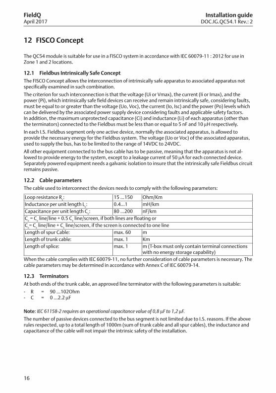
12.2 Cable parametersThe cable used to interconnect the devices needs to comply with the following parameters:
Loop resistance Rc: 15 ...150 Ohm/KmInductance per unit length Lc: 0.4…1 mH/kmCapacitance per unit length Cc: 80 ...200 nF/kmCc = Cc line/line + 0.5 Cc line/screen, if both lines are floating orCc= Cc line/line + Cc line/screen, if the screen is connected to one lineLength of spur Cable: max. 60 mLength of trunk cable: max. 1 KmLength of splice: max. 1 m (T-box must only contain terminal connections
with no energy storage capability)When the cable complies with IEC 60079-11, no further consideration of cable parameters is necessary. The cable parameters may be determined in accordance with Annex C of IEC 60079-14.
12.3 TerminatorsAt both ends of the trunk cable, an approved line terminator with the following parameters is suitable:
- R = 90 ...102Ohm- C = 0 ...2.2 µF
Note: IEC 61158-2 requires an operational capacitance value of 0,8 µF to 1,2 µF.
The number of passive devices connected to the bus segment is not limited due to I.S. reasons. If the above rules respected, up to a total length of 1000m (sum of trunk cable and all spur cables), the inductance and capacitance of the cable will not impair the intrinsic safety of the installation.
12 FISCO Concept

17
FieldQApril 2017
Installation guideDOC.IG.QC54.1 Rev.: 2

18
FieldQApril 2017
Installation guideDOC.IG.QC54.1 Rev.: 2

19
FieldQApril 2017
Installation guideDOC.IG.QC54.1 Rev.: 2

FieldQ
World Area Configuration Centers (WACC) offer sales support, service, inventory and commissioning to our global customers. Choose the WACC or sales office nearest you:
www.emerson.com/fieldq
©2017 Emerson. All rights reserved.
The Emerson logo is a trademark and service mark of Emerson Electric Co. FieldQ is a mark of the Emerson family of companies. All other marks are property of their respective owners.
The contents of this publication are presented for information purposes only, and while every effort has been made to ensure their accuracy, they are not to be construed as warranties or guarantees, express or implied, regarding the products or services described herein or their use or applicability. All sales are governed by our terms and conditions, which are available on request. We reserve the right to modify or improve the designs or specifications of our products at any time without notice.
NORTH & SOUTH AMERICA 19200 Northwest Freeway Houston, TX 77065 T +1 281 477 4100 F +1 281 477 2809
Av. Hollingsworth, 325, Iporanga Sorocaba, SP 18087-105 Brazil T +55 15 3238 3788 F +55 15 3228 3300
ASIA PACIFIC No. 9 Gul Road #01-02 Singapore 629361 T +65 6777 8211 F +65 6268 0028 No.1 Lai Yuan Road Wuqing Development Area Tianjin 301700 P.R.China T +86 22 8212 3300 F +86 22 8212 3308
MIDDLE EAST & AFRICA P. O. Box 17033 Dubai United Arab Emirates T +971 4 811 8100 F +971 4 886 5465
P. O. Box 10305 Jubail 31961 Saudi Arabia T +966 3 340 8650 F +966 3 340 8790
24 Angus Crescent Longmeadow Business Estate East P.O. Box 6908; Greenstone; 1616 Modderfontein, Extension 5 South Africa
T +27 11 451 3700F +27 11 451 3800
EUROPE Berenyi u. 72-100Videoton Industry ParkBuilding #230Székesfehérvár 8000HungaryT +36 22 53 09 50F +36 22 54 37 00
For complete list of sales and manufacturing sites, please visit www.emerson.com/actuationtechnologieslocations or contact us at [email protected]