Embed Size (px)
Citation preview
Field Testing of Machine Tool Diagnostic Techniques Using Surface Metrology
J. Raja - Submitted by D. J. Whitehouse (1). Microengineering Centre, University of Warwick/UK
Surfaces generated by machine t o o l s are f i n g e r p r i n t o f t h e machine and t o o l combination. Any change i n the c o n d i t i o n o f e i t h e r should be r e f l e c t e d i n the component produced s p e c i a l l y i n the na ture o f cmponent surfaces generated and i t s dimensions. I f the var iab les invo lved i n the process l i k e c u t t i n g t o o l , w o r b i e c e mater ia l and c u t t i n g cond i t ions are standardized then the v a r i a t i o n i n the cond i t ion o f the machine alone would a f f e c t the component produced. The changes i n the cmponent surfaces and dimensions could then be used t o diagnose the cond i t ion o f the machine t o o l . This paper summarizes the r e s u l t s o f f i e l d t r i a l s o f t h i s type o f d iagnos t ic technique app l ied t o CNC m i l l i n g machine.
1. ItlTROOUCTION
i t i s beconin? necessary t o mon i to r the c o n d i t i o n o f i n d i v i d u a l machine t o o l s to avo id e x y n s i v e stoppage o r f a i l u r e . t o o l s i n c l u d i n q CNC a re seldom r e c a l i b r a t e d o r reassessed f o r geometric c a p a b i l i t y dur ing t h e i r l i f e t ime. The economic use of CNC requ i res such s c r u t i n y dur ing t h e i r l i f e t ime. There i s there fore a d e f i n i t e need f o r mon i to r ing the c o n d i t i o n o f machine t o o l s f o r f a i l u r e and f o r assessing the performance and hence process c a p a b i l i t y . I n t h i s paper an at tempt has been made t o use the component produced t o monitor the c o n d i t i o n o f the machine on a r o u t i n e basis w i t h a minimum d i s r u p t i o n of work schedule.
2 . EXISTING NETHODS
Sound and v i b r a t i o n have been used e a r l i e r t o monitor the c o n d i t i o n o f machine t o o l -1,Z:. machines the v i b r a t i o n f re iuency spectrum has a c h a r a c t e r i s t i c shape when the machine i s i n good cond i t ion . t o develop i n the machine some o f the fo rces a c t i n g on the p a r t s a re changed, thereby i n f l u e n c i n g the v i b r a t i o n spectrum. On t h i s basis v i b r a t i o n measurement and ana lys is i s used f o r c o n d i t i o n monitor ing. Sound i s a lso used using the same p r i n c i p l e bu t the i n t e r p r e t a t i o n o f sound s igna ls has been more d i f f i c u l t than v i b r a t i o n c3:. I n both cases spec ia l ins t rumenta t ion i s requ i red t o record the s igna l and the transducer has t o be mounted on the machine i n the case o f v i b r a t i o n . extended from r o t a t i n g machinery are n o t best s u i t e d f o r monitor- i n g the o v e r a l l performance of machine t o o l s .
3 . PROPOSED YETHOD
The component produced by the machine t o o l can be taken as the f i n g e r p r i n t o f the machine and t o o l c m b i n a t i o n . When i n opera t ion any change i n the c o n d i t i o n o f e i t h e r w i l l be r e f l e c t e d i n the component produced, e s p e c i a l l y i n the nature o f component surfaces and i t s dimensions. I f the var iab les invo lved i n the c u t t i n g process l i k e the c u t t i n g t o o l , workpiece mater ia l and c u t t i n g cond i t ions are standardized then the v a r i a t i o n i n the machine c o n d i t i o n alone cou ld be expected t o in f luence the surface f i n i s h . d e t a i l t o mon i to r the c o n d i t i o n o f the machine t o o l . It i s p l a u s i b l e there fore t o suppose t h a t s p e c i f i c fea tures o f the surface can be used t o p i c k o u t c e r t a i n machine c h a r a c t e r i s t i c s , e.g. roundness o f holes f o r bear ing f a u l t s , waviness f o r s l i d e wear [4,5]. from t ime t o t ime and i t s surface and dimensional c h a r a c t e r i s t i c s evaluated t o monitor the longterm c o n d i t i o n o f the machine and hence t o enable some p r e d i c t i o n o f f a i l u r e t o be made.
The var ious fea tures o f the t e s t component t o be examined a r e as fo l lows. squareness o f edges and absolute dimensions would be used t o mon i to r the c o n d i t i o n o f the slideways and sp ind le assembly. secondary t e x t u r e o f the surface i s u s u a l l y associated w i t h inaccuracies o f machine t o o l s l i k e l a c k o f s t ra igh tness o r v i b r a t i o n . e x t r a c t the c o n d i t i o n o f the machine t o o l . I n a d d i t i o n because the pr imary t e x t u r e can be a l t e r e d by the changes i n the dynamic c o n d i t i o n o f the machine when the f a u l t s develop t h i s cou ld a l s o be examined. S i m i l a r l y the roundness o f holes could be measured t o revea l the c o n d i t i o n o f the machine, e s p e c i a l l y the sp ind le assembly.
4. MATHEMATICAL TOOLS
I n o rder t o be ab le t o e x t r a c t the maximum amount o f data from t h e surface t e x t u r e t h e p r o f i l e s were stored i n d i g i t i z e d form. ?recess techniques. Fast Four ie r t ransform methods were used t o compute the power spec t ra l dens i ty f u n c t i o n t o study the wave- l e n g t h content o f the p r o f i l e . S t a t i s t i c a l ana lys is o f the p r o f i l e s was a lso c a r r i e d o u t t o reveal the changes i n surface oarameters due t o machine cond i t ion . d i s t r i b u t i o n s together w i t h skew and k u r t o s i s values and the
As more CNC and f l e x i b l e manufacturing systems are develoned
Nachine
I t has been found t h a t f o r most
When f a u l t s begin
These techniques which were
The surface f i n i s h obtained cou ld then be analysed i n
Thus a standard t e s t component could be machined
The geometric accuracy, e.g. p a r a l l e l i s m ,
The
The longer wavelengths there fore could be examined t o
These d i g i t i z e d p r o f i l e s were then analysed using random
Amplitude and slope
curva ture o f the v a l l e y s were computed t o evaluate the c u t t i n g process i n r e l a t i o n t o the shape o f the t o o l and feed.
5 . METHOD ADOPTED
The f i r s t stage i n t h i s approach i s t o e s t a b l i s h t h a t surfaces generated are a f f e c t e d by machine t o o l c o n d i t i o n i n a way whicli could be i d e n t i f i e d and used to9crea te a data bank of p r o f i l e s f o r poss ib le e r r o r cond i t ions 4 . A Br idgepor t CNC ser ies I m i l l i n g machine a v a i l a b l e i n tee-laboratory was chosen to assess the f e a s i b i l i t y o f t h i s approach. This machine i s a lso i n use i n many small i n d u s t r i e s i n the v i c i n i t y and hence access t o the machines f o r f i e l d t e s t i n q Wac e a s i l y a v a i l a b l e .
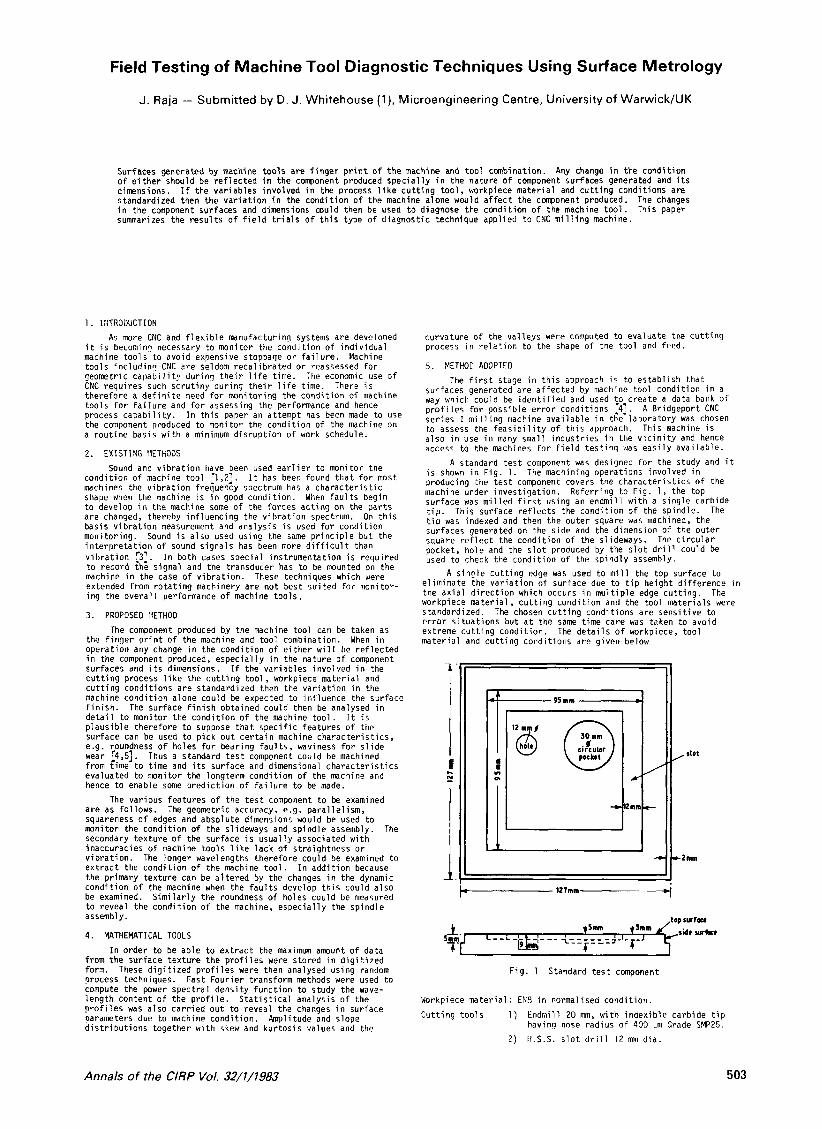
i s shown i n Fig. 1. The machining operat ions invo lved i n producing the t e s t component covers the c h a r a c t e r i s t i c s of the machine under i n v e s t i g a t i o n . Refer r ing t o F i g . 1 , the top surface was m i l l e d f i r s t using an endmil l w i t h a s i n g l e carbide t i p . This sur face r e f l e c t s the c o n d i t i o n o f the spindle. The t i p was indexed and then the ou ter square was machined, the surfaces generated on the s ide and the dimension o f the o u t e r square r e f l e c t the c o n d i t i o n o f the slideways. pocket, ho le and the s l o t produced by the s l o t d r i l l could be used t o check the c o n d i t i o n o f the sp ind ly assembly.
A s i n r l e c u t t i n g edge was used t o m i l l the t o p surface t o
A standard t e s t component was designed f o r the study and i t
The c i r c u l a r
e l i m i n a t e the v a r i a t i o n o f surface due t o t i p he igh t d i f f e r e n c e i n the a x i a l d i r e c t i o n which occurs i n m u l t i p l e edge c u t t i n g . The workpiece m a t e r i a l , c u t t i n g c o n d i t i o n and the t o o l m a t e r i a l s were standardized. The chosen c u t t i n g cond i t ions are s e n s i t i v e t o e r r o r s i t u a t i o n s b u t a t the same t ime care was taken t o avo id extreme c u t t i n g c o n d i t i o n . mater ia l and c u t t i n g cond i t ions are g iven below
The d e t a i l s o f workpiece, t o o l
,top rwrpu
Fig . 1 Standard t e s t component
Workpiece m a t e r i a l : EN9 i n normalised c o n d i t i o n .
C u t t i n g t o o l s 1 ) E n d n i l l 20 mm, with i n d e x i b l e carb ide t i p havinq nose rad ius o f 400 :.m Grade SMP25.
2 ) 1I.S.S. s l o t d r i l l 12 mm d i a .
Annals of the ClRP Vol. 32/1/1983 503
Cut t i ng cond i ti ons
Top sur face 2500 rpm 150 d r e v Side sur face 2500 rpm 100 .:m,'rev C i r c u l a r pocket and s l o t 1000 rpm 38 ,&rev Hole 1000 rm 12.5 ... m;rev
were se lec ted f o r i n v e s t i g a t i o n . r e s u l t s i n g r e a t e r c learance a f f e c t s the performance o f the machine. This c o n d i t i o n was simulated by s lackening the n i b s t r i p (which a l s o r e s u l t s i n g r e a t e r c learance) . sur face generated were analysed and used as bas is f o r f u t u r e d iagnos is . and i t was increased up to 100 -m i n each a x i s . The clearance l e v e l s a re g iven below.
speed fee
The cond i t io r l o f the t a b l e and saddle s l ideway and s ? i n d l e The wear o f slideways which
The e f f e c t on t h e
The clearance s p e c i f i e d by the manufacturer i s 12.5 . m
X 12.5 :.m 50 um 100 ..m Y 12.5 ::m 50 100 .:m
The t e s t componept shown i n F ig . 1 was made f o r a l l the combinat ion o f c learance l e v e l s . I n a l l n ine t e s t components were made and s i x p r o f i l e s were recorded from each t e s t component us ing a T a l y s u r f 5 which i s a t tached t o MINC-11 m i n i computer f o r analog t o d i g i t a l conversion o f p r o f i l e s . Four p r o f i l e s f rom the sides were d i g i t i z e d a t 10 50 mm of the surface was recorded. Two p r o f i l e s f rom the t o p surface were d i g i t i z e d a t 5 .,m i n t e r v a l and 5000 ord ina tes represent ing 25 mm o f the sur face was s to red . f i l t e r e d t o remove wavelengths longer than 10 mm i n the case o f s i d e sur face and 5 mn i n the case o f t o p sur face and then analysed i n d e t a i l . were evaluated, us ing a Talyrond 200 a l s o connected t o the m i n i computer f o r s t o r i n g the data i n d i g i t i z e d form.
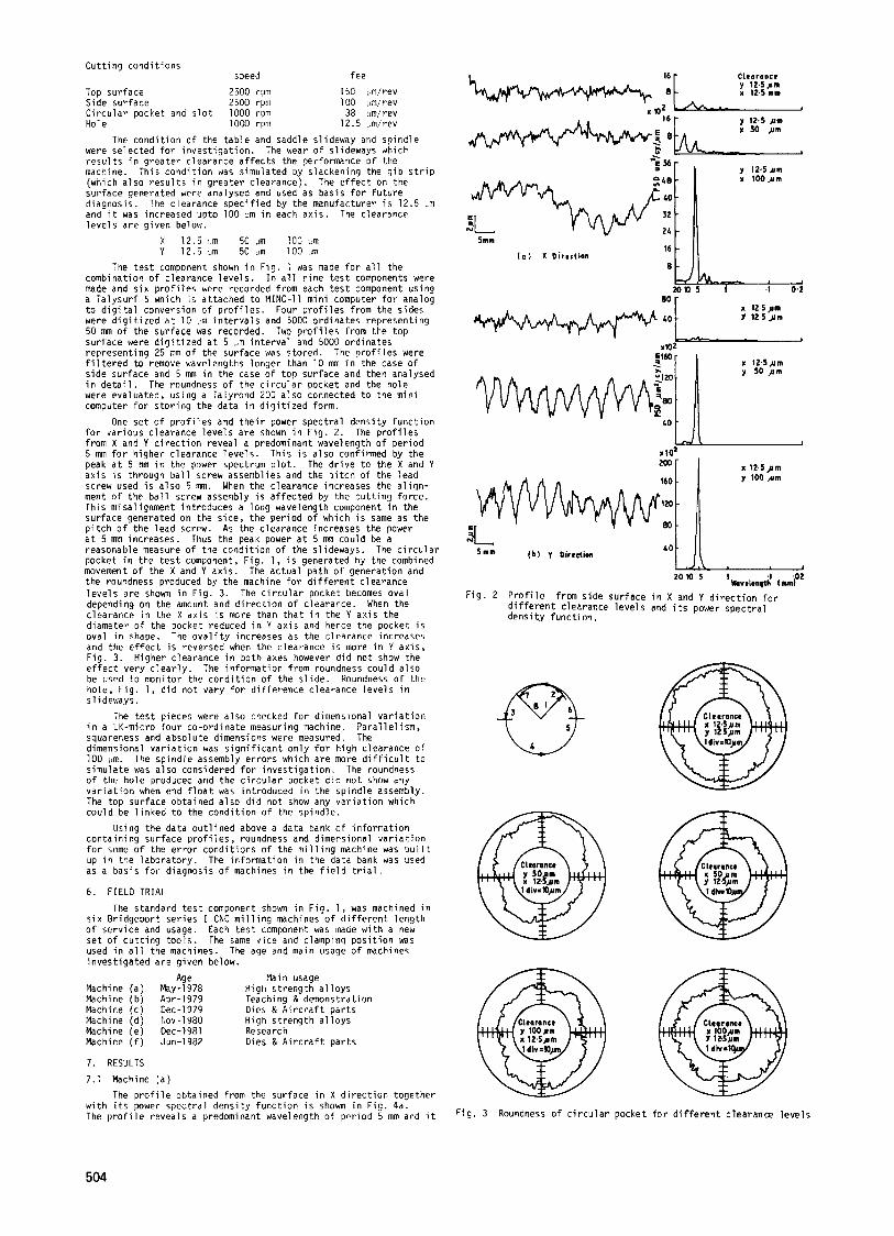
One s e t o f p r o f i l e s and t h e i r power s p e c t r a l dens i ty f u n c t i o n f o r var ious c learance l e v e l s a r e shown i n F ig . 2. f rom X and Y d i r e c t i o n revea l a predominant wavelength o f p e r i o d 5 mm f o r h igher c learance l e v e l s . Th is i s a l s o conf i rmed by t h e peak a t 5 mm i n the power spectrum p l o t . a x i s i s through b a l l screw assemblies and the p i t c h o f the lead screw used i s a l s o 5 mn. When the clearance increases the a l i g n - ment o f the b a l l screw assembly i s a f f e c t e d by the c u t t i n g f o r c e . This misal ignment in t roduces a long wavelength component i n t h e surface generated on the s ide , t h e p e r i o d o f which i s same as the p i t c h o f t h e l e a d screw. As the c learance increases the power a t 5 mm increases. reasonable measure o f the c o n d i t i o n o f t h e s l ideways. pocket i n the t e s t component, F i g . 1, i s generated by the combined movement o f the X and Y a x i s . the roundness produced by the machine f o r d i f f e r e n t c learance l e v e l s a r e shown i n F ig . 3. The c i r c u l a r pocket becomes ova l depending on the amount and d i r e c t i o n o f c learance. When the clearance i n the X a x i s i s more than t h a t i n the Y a x i s the diameter o f the pocket reduced i n Y a x i s and hence the pocket i s ova l i n shape. The o v a l i t y increases as the c learance increases and the e f f e c t i s reversed when t h e clearance i s more i n Y a x i s , F ig . 3 . e f f e c t very c l e a r l y . be used t o mon i to r the c o n d i t i o n o f the s l i d e . Koundness o f the hole, F i g . 1, d i d n o t vary f o r d i f f e r e n c e clearance l e v e l s i n s l ideways.
The t e s t p ieces were a l s o checked f o r dimensional v a r i a t i o n i n a LK-micro f o u r co-ord ina te measuring machine. P a r a l l e l i s m , squareness and abso lu te dimensions were measured. The dimensional v a r i a t i o n was s i g n i f i c a n t o n l y f o r h igh c learance o f 100 m. The s p i n d l e assembly e r r o r s which a r e more d i f f i c u l t t o s imu la te was a l s o considered f o r i n v e s t i g a t i o n . o f the h o l e produced and t h e c i r c u l a r pocket d i d n o t show any v a r i a t i o n when end f l o a t was in t roduced i n the s p i n d l e assembly. The top surface ob ta ined a l s o d i d no t show any v a r i a t i o n which cou ld be l i n k e d t o the c o n d i t i o n o f the sp ind le .
con ta in ing sur face p r o f i l e s , roundness and dimensional v a r i a t i o n f o r some o f the e r r o r c o n d i t i o n s o f the m i l l i n g machine was b u i l t up i n the l a b o r a t o r y . The in fo rmat ion i n the data bank was used as a bas is f o r d iagnos is o f machines i n the f i e l d t r i a l .
6 . FIELD TRIAL
s i x Br idgepor t s e r i e s I CNC m i l l i n g machines o f d i f f e r e n t l e n g t h o f s e r v i c e and usage. s e t o f c u t t i n g t o o l s . used i n a l l the machines. i n v e s t i g a t e d a r e g iven below.
Machine (a ) May-1978 High s t r e n g t h a l l o y s Machine (b) Apr-1979 Teaching & demonstrat ion Machine ( c ) Dec-1979 Dies E A i r c r a f t p a r t s Machine (d) Nov-1980 High s t r e n g t h a l l o y s Machine (e ) Dec-1981 Research Macnine ( f ) Jun-1982 Dies & A i r c r a f t p a r t s
7. RESULTS
7.1 Machine ( a )
The p r o f i l e obtained from the sur face i n X d i r e c t i o n together w i t h i t s power s p e c t r a l d e n s i t y f u n c t i o n i s shown i n F ig . 4a. The p r o f i l e revea ls a predominant wavelength o f p e r i o d 5 mm and i t
i n t e r v a l s and 5000 ord ina tes represent ing
The g r o f i l e s were
The roundness o f the c i r c u l a r pocket and the ho le
The p r o f i l e s
The d r i v e t o the X and Y
Thus the peak power a t 5 run cou ld be a The c i r c u l a r
The ac tua l pa th of genera t ion and
Higher c learance i n bo th axes however d i d no t show the The in fo rmat ion f rom roundness cou ld a lso
The roundness
Using t h e data o u t l i n e d above a data bank o f i n f o r m a t i o n
The standard t e s t component shown i n F ig . 1, was machined i n
Each t e s t component was made w i t h a new The same v i c e and clamping p o s i t i o n was
The age and main usage o f machines
Age Llain usage
Clearance y x l Z . 5 . m 12.5 mm
' .d - 5mm
16 - I f f 1 X Direction
s c
y 12.5um x 100ym
a 1 2 4 p m Y 12.5 pm
LL----- x10'
zo lo 'wwelenqti' i m n P Fig . 2 P r o f i l e frm s i d e sur face i n X and Y d i r e c t i o n f o r
d i f f e r e n t clearance l e v e l s and i t s power s p e c t r a l dens i t y func ti on.
Y 1OOnm
F i g . 3 Roundness of c i r c u l a r pocket f o r d i f f e r e n t c learance l e v e l s
504
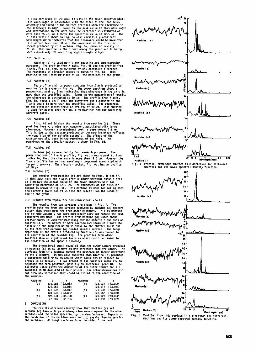
is a lso confirmed by the peak a t 5 mm in the power spectrum plot. This wavelength i s associated with the pitch of the lead screw assembly and found i n the surface prof i les when the clearance i n the slideways i s high. Based on the peak value a t th i s wavelength and information i n the data bank the clearance is estimated as more than 75 am, well above the specified value of 12.5 m. The Y axis prof i le shown i n F i g . 5a also reveals a predominant wavelength which indicates that the clearance could be more than 12.5 m but less than 50 m. The roundness of the circular pocket produced by this machine, Fig. 6a, shows an ovality of 25 .Im.
used extensively for machining high strength alloys.
7.2 Machine ( b )
purposes. The prof i le from X axis , F i g . 4b and the prof i le from Y axis , F ig . 56, show no evidence of any excessive clearance. The roundness of c i rcular pocket i s shown i n Fig. 6b. machine is the leas t ut i l ized of a l l the machines i n the group.
7.3 Machine (c)
machine (c ) i s shown i n Fig. 4c. The power spectrm shows a predominant peak a t 5 nun indicating tha t clearance in the axis i s more than the specified value. Based on the comparison of resul ts the clearance is estimated as 50 pm. The prof i le from Y axis , Fig. 5c, shows a small peak and therefore the clearance i n the Y axis could be more t h a n the specified value. The roundness of the circular pocket shows an oval i ty of 40 :m. T h i s machine i s used for making dies f o r moulding machines and f o r machining a i r c r a f t par ts .
7.4 Machine (d) Figs. 4d and 5d show the resul ts from machine (d). These
prof i les have no predominant component associated w i t h large clearance. T h i s i s due to the chat ter produced by the machine which re f lec ts the condition of the spindle assembly. chat ter was also seen i n the roundness of the hole. The roundness of the c i rcu lar pocket is shown i n Fig. 6d.
7.5 Machine (e ) Machine (e) is used mainly for research purposes. The
power spectrum of X axis prof i le , Fig. 4e, shows a peak a t 5 mm indicating tha t the clearance is more than 12.5 zm. However the Y axis prof i le has no long wavelength component associated w i t h larger clearance. The circular pocket, Fig. 6e, has a n ovality of 20 ym. 7.6 Machine ( f )
The resu l t s from machine ( f ) a re shown i n Figs. 4f and 5f . In t h i s case only the Y axis prof i le power spectrum shows a peak a t 5 nm but the actual value of the power compares w i t h the specified clearance of 12.5 dm. The roundness of the circular pocket is shown i n F i g . 6f. T h i s machine i s used for making dies and a i r c r a f t parts and i t is a l so the l a t e s t from the point of age i n the group.
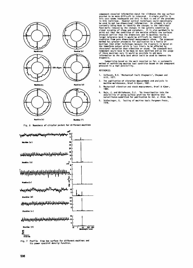
7.7 Results from topsurface and dimensional checks The resu l t s from top surfaces a re shown i n Fig. 7. The
prof i le obtained from the surface produced by machine (a ) appears bet ter t h a n those obtained from other machines. T h i s i s because the spindle assembly had been completely serviced before the test component was made. chat ter marks is used for machining similar materials and jobs as machine ( a ) . spindle i n the long run which i s shown by the chat ter marks and by the fac t tha t machine ( a ) needed spindle service. The large amplitude of the prof i le produced by machine (c) was traced to the condition of the carbide t ip . T h e prof i les from other machines show no s ignif icant features which could be linked to the condition of the spindle assembly.
The dimensional check revealed that the outer square produced by machine ( a ) is 50 pm mre i n one direction than the other. The surfaces from this machine showed the presence of larger clearance i n the slidenays. a component smaller by an amount which could not be related to errors i n slideways. I t was traced to the machines inabi l i ty to relocate the zero position, possibly an electr ical problem. The following Table gives the dimension of the outer square for a l l machines i n nm measured a t four points. not show any variation that could be linked to the condition of the machine.
Machine X Y Machine X Y
This machine is the oldest among the group and is k i n g
Machine (b) is used mainly for teaching and demonstration
T h i s
The prof i le and i ts power spectrum from X axis produced by
However a predominant peak is seen around 1.6 mn.
The effect of the
The prof i le from machine (d) which shows
The nature of work carr ied out seems to a f fec t the
I t was also observed tha t machine (c) produced
The other dimensions did
(a ) 123.088 123.012 (d) 123.037 123.009 123.055 123.014 123.017 123.014
( b ) 123.032 123.017 (e ) 123.037 123.050 123.032 123.022 123.052 123.050
( c ) 122.834 122.798 ( f ) 123.027 123.022 122.809 122.786 123.037 123.009
8. CONCLUSION The resul ts obtained clear ly show tha t machine (a ) and
machine (c) have a large slideway clearance compared to the other machines and the value specified by the manufacturer. Reports on the condition of the machines were sent to enable them to service the machines. Although surfaces from the s ide of the t e s t
Uachinr I b 1
Yr I
W' 0 Urchlnr It1 nr
F i g , 4 Prof i le from side surface i n X direction for different machines and i t s power spectral density function.
@L Uachinr l a 1
b8 56t I
8
1
24 r
Fig. 5 Prof i le from side surface i n Y direction for different machines and its power spectral density function.
505
Machine(e) Mechin lb 1
1 MV. @ WlchiM(c) Machine Id1
Maohine lr t kchine I f )
Fig. 6 Roundness of c i rcu lar pocket for different machines
M d i n e l c l
Machine Id )
Machine If1
u
component revealed information about the slideways the top surface provied to be more d i f f i c u l t to interpret . A single prof i le in this case seems inadequate and this i n fac t is one of the problems i n th is technique. However optical techniques could conceivably be used to get two-dimensional information. An attempt is a lso currently being made t o identify the changes i n the individual feed marks induced by the changes i n the spindle condition by closer scrutiny of slope and curvature. point out tha t t h e condition of the machine affects the surfaces produced ear l ie r than the dimensions and i n machines having a larger tolerance band i t would be d i f f i c u l t to identify the condition from pure dimensional measurements alone. The proposed method has greater prospects for application to a family of machines than other techniques because the diagnosis is based on the inmediate output which is less 1ikel.v to be affected by s t ructural variation than vibration or sound. The standard test component would have to be made on more machines and as the usage of these machines vary i t would be possible to add more information to the data bank which could be used to improve the diagnosis.
method of monitoring machine tool condition based on the component produced is a real possibi l i ty .
REFERENCES
1. Collacot. R.A. 'Mechanical Fault Diagnosis', Chapman and Hil l , 1977.
2. The application of vibration measuremnt and analysis i n machine maintenance, Bruel & Kjaer, 1981.
3. Mechanical vibration and shock measurement, Bruel & Kjaer, 1980.
4 . Raja, J. and Whitehouse, D.J. 'An investigation into the possibi l i ty o f using surface prof i les f o r machine tool surveillance-subnitted for publication t o Int . J . Prod. Res.
5. Schlesinger. G . Testing o f machine tools Pergamn Press, 1978.
I t is a lso worthwhile to
Summarizing based on the work reported so f a r , a systematic
@L 0.52 mm
Fig. 7 Profi le from top surface f o r different machines and i t s power spectral density function.
506