Embed Size (px)
Citation preview
International Workshop on SMART MATERIALS, STRUCTURES & SHM
NDT in Canada 2013 Conference & NDT for the Energy Industry
October 7-10, 2013 Calgary, Alberta, CANADA
2013 CANSMART CINDE IZFP
Field Experience and Best Practices
for Laser Assessment of Pipeline Damage
David Mackintosh
Tom Taylor
George Bryant
Acuren Group Inc., 7450 18 St NW, Edmonton AB T6P 1N8
ABSTRACT
Laser surface scanning is an accurate and cost-effective solution to the challenge of assessing
external pipeline damage. With automated interaction rules, the system can easily handle dozens
or even hundreds of corrosion features at once and produce burst pressures based on ASME
B31G code immediately on the job site. Laser scanning is also ideally suited to documenting and
assessing mechanical damage such as dents and out-of round features. As with corrosion, dent
dimensional analysis can be carried out on the job site, or, alternatively, used offsite as input to
finite element or strain analysis software. Laser scanning is a very reliable and repeatable
method, but only in the hands of a qualified operator with appropriate procedures and quality
controls. During the initial evaluation and approval process, it was recognized that the optically-
based technology would be new and foreign to many NDT field technicians. There are also
limitations with scanners, such as the ability to scan inside deep cracks, and limitations to
analysis software, such as the effects of bends on results. This paper outlines pipeline
applications of laser scanning and will discuss the quality program undertaken to verify the
system, train technicians, develop procedures, and produce reliable results.
Keywords: laser, scanning, corrosion, pipeline, integrity.
2013 CANSMART CINDE IZFP
INTRODUCTION
A laser scanner is an instrument that takes point measurements on the outside surface of an
object and produces data that describes the object’s shape [1] (and sometimes other properties
such as colour or texture). Specialized software can then be used to determine the object’s
dimensions or to highlight deviations and imperfections. As such, laser scanners are well-suited
to the job of evaluating corrosion and mechanical damage on pipelines – with the proper
procedure, quality controls, and a good understanding of the strengths and limitations of the
technology. Due to their precision and simplicity, the corrosion assessment methods prescribed
in ASME B31G code [2] are well suited to both manual and automated analysis. An advantage of
the laser scanning method is that it provides a fine mesh of data points in a format that can easily
be processed by corrosion assessment algorithms [3, 4] or exported to finite element software for
advanced analysis.
LASER SCANNING FOR PIPELINES
Advancements in commercially available computing power have improved the speed,
accuracy, and viability of laser scanners [5], which has resulted in more productive and effective
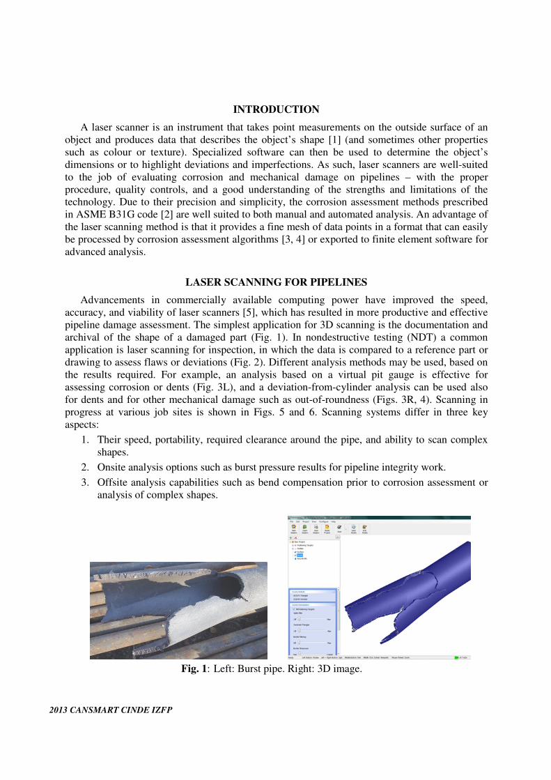
pipeline damage assessment. The simplest application for 3D scanning is the documentation and
archival of the shape of a damaged part (Fig. 1). In nondestructive testing (NDT) a common
application is laser scanning for inspection, in which the data is compared to a reference part or
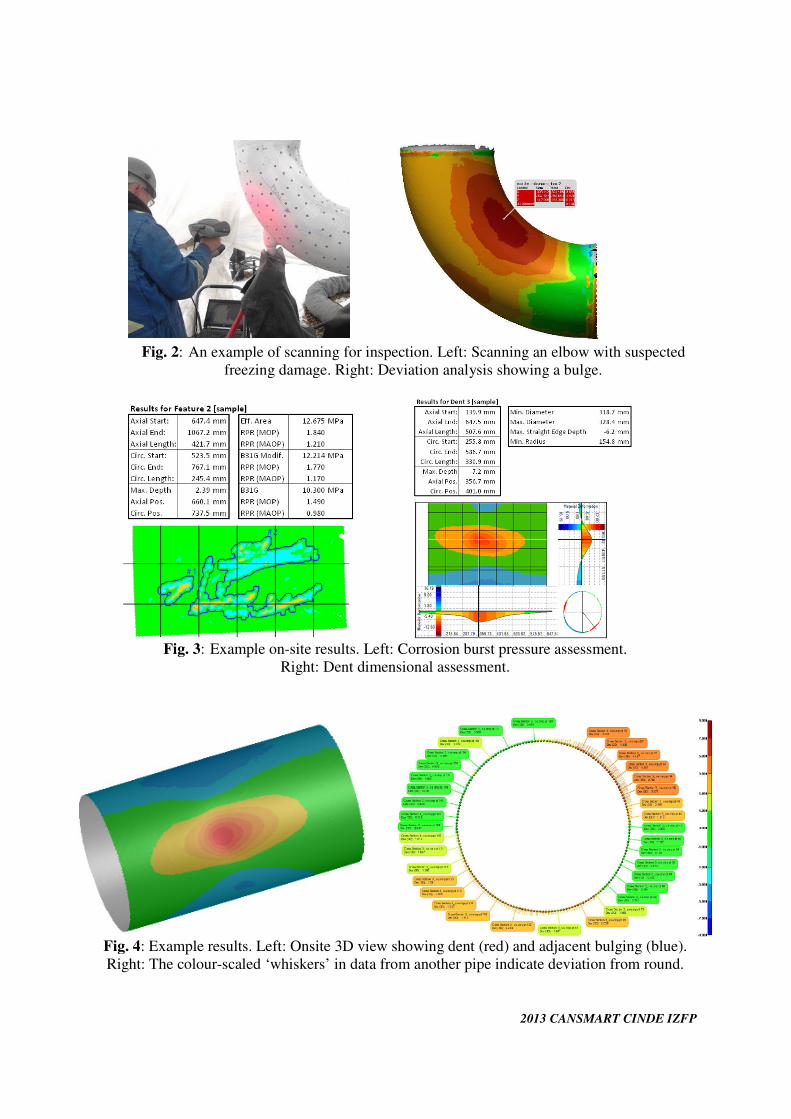
drawing to assess flaws or deviations (Fig. 2). Different analysis methods may be used, based on
the results required. For example, an analysis based on a virtual pit gauge is effective for
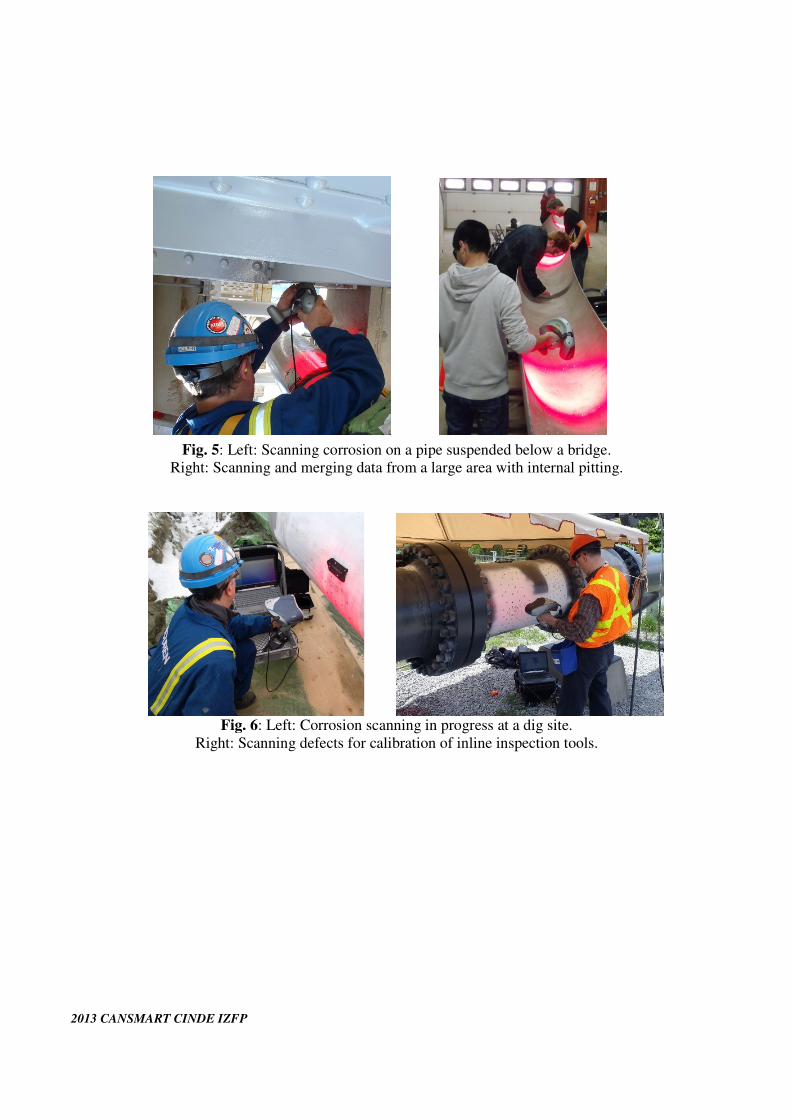
assessing corrosion or dents (Fig. 3L), and a deviation-from-cylinder analysis can be used also
for dents and for other mechanical damage such as out-of-roundness (Figs. 3R, 4). Scanning in
progress at various job sites is shown in Figs. 5 and 6. Scanning systems differ in three key
aspects:
1. Their speed, portability, required clearance around the pipe, and ability to scan complex
shapes.
2. Onsite analysis options such as burst pressure results for pipeline integrity work.
3. Offsite analysis capabilities such as bend compensation prior to corrosion assessment or
analysis of complex shapes.
Fig. 1: Left: Burst pipe. Right: 3D image.
2013 CANSMART CINDE IZFP
Fig. 2: An example of scanning for inspection. Left: Scanning an elbow with suspected
freezing damage. Right: Deviation analysis showing a bulge.
Fig. 3: Example on-site results. Left: Corrosion burst pressure assessment.
Right: Dent dimensional assessment.
Fig. 4: Example results. Left: Onsite 3D view showing dent (red) and adjacent bulging (blue).
Right: The colour-scaled ‘whiskers’ in data from another pipe indicate deviation from round.
2013 CANSMART CINDE IZFP
Fig. 5: Left: Scanning corrosion on a pipe suspended below a bridge.
Right: Scanning and merging data from a large area with internal pitting.
Fig. 6: Left: Corrosion scanning in progress at a dig site.
Right: Scanning defects for calibration of inline inspection tools.
2013 CANSMART CINDE IZFP
RESEARCH AND DUE DILIGENCE
Since there are next to no international standards that apply to close-range scanning [7], let
alone for pipeline damage assessment, a robust and auditable quality program, including training,
qualifications, and examination procedures is essential. Laser scanners are often promoted as an
‘ultimate solution,’ however they can also be seen as just one more tool in the NDT box. As with
any technology, it is important to verify its performance and to determine its strengths and
limitations. Elements of our internal verification program include:
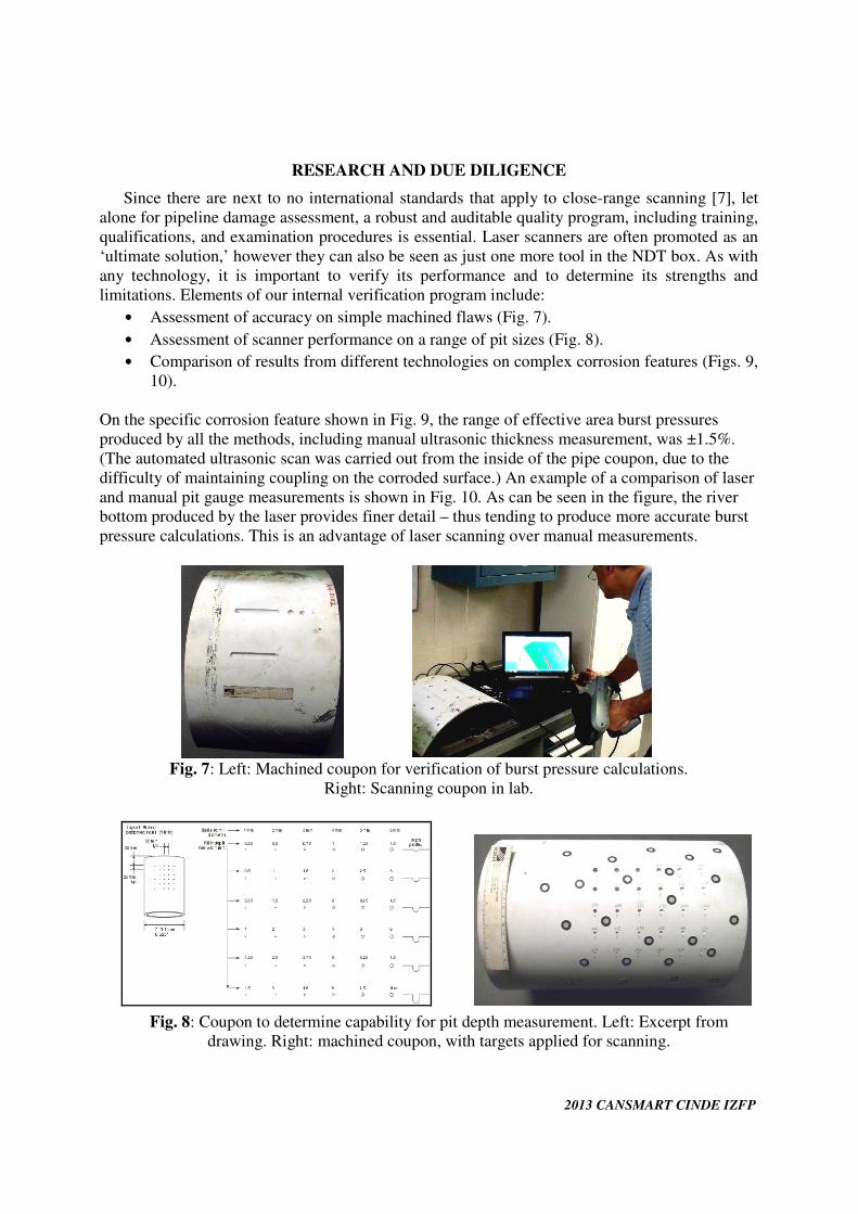
• Assessment of accuracy on simple machined flaws (Fig. 7).
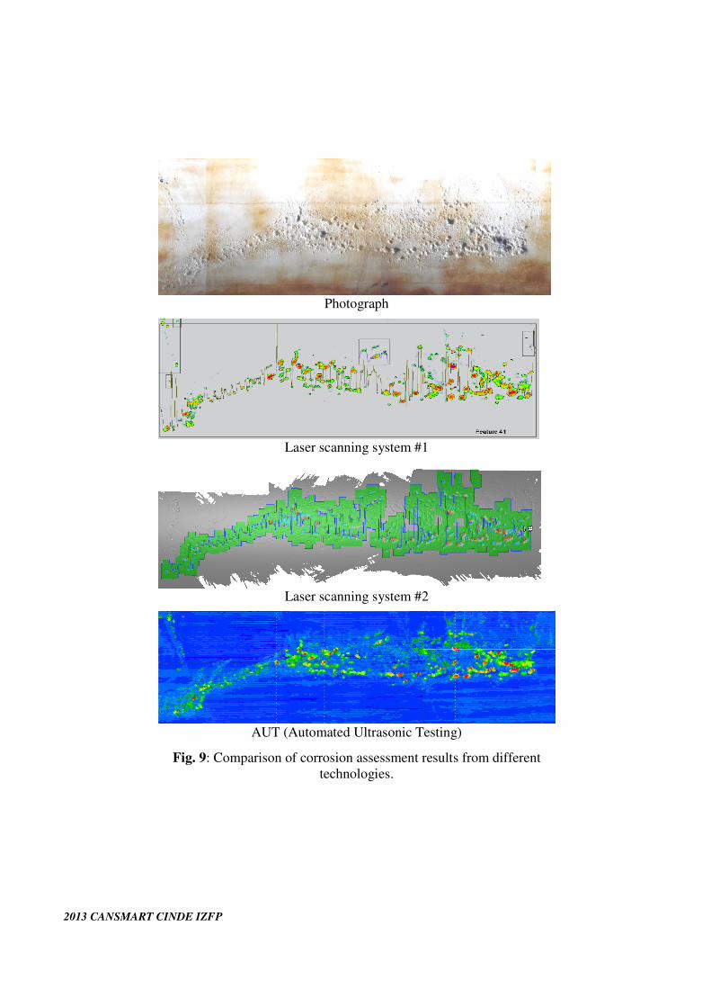
• Assessment of scanner performance on a range of pit sizes (Fig. 8).
• Comparison of results from different technologies on complex corrosion features (Figs. 9,
10).
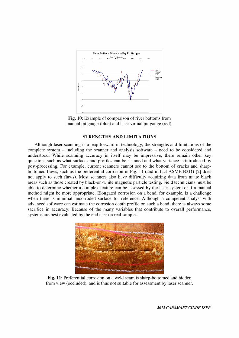
On the specific corrosion feature shown in Fig. 9, the range of effective area burst pressures
produced by all the methods, including manual ultrasonic thickness measurement, was ±1.5%.
(The automated ultrasonic scan was carried out from the inside of the pipe coupon, due to the
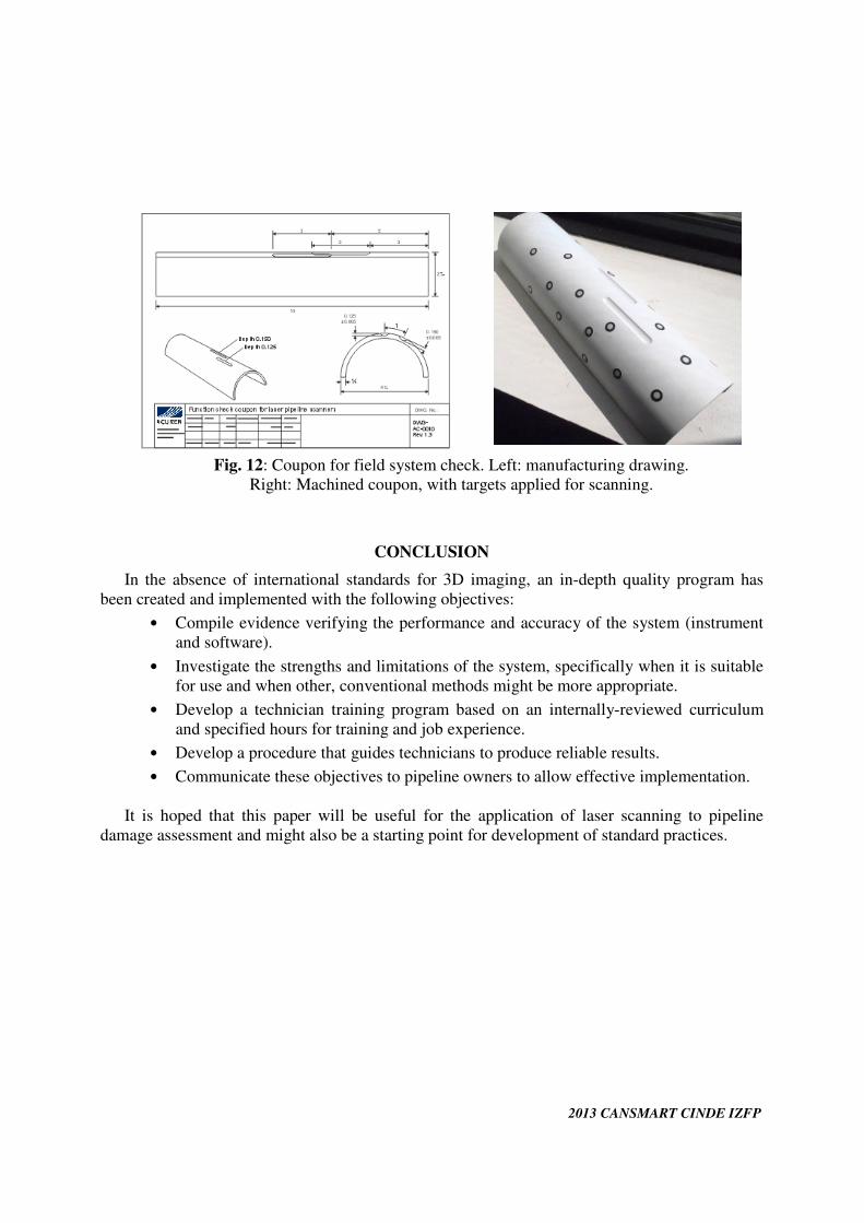
difficulty of maintaining coupling on the corroded surface.) An example of a comparison of laser
and manual pit gauge measurements is shown in Fig. 10. As can be seen in the figure, the river
bottom produced by the laser provides finer detail – thus tending to produce more accurate burst
pressure calculations. This is an advantage of laser scanning over manual measurements.
Fig. 7: Left: Machined coupon for verification of burst pressure calculations.
Right: Scanning coupon in lab.
Fig. 8: Coupon to determine capability for pit depth measurement. Left: Excerpt from
drawing. Right: machined coupon, with targets applied for scanning.
2013 CANSMART CINDE IZFP
Photograph
Laser scanning system #1
Laser scanning system #2
AUT (Automated Ultrasonic Testing)
Fig. 9: Comparison of corrosion assessment results from different
technologies.
2013 CANSMART CINDE IZFP
Fig. 10: Example of comparison of river bottoms from
manual pit gauge (blue) and laser virtual pit gauge (red).
STRENGTHS AND LIMITATIONS
Although laser scanning is a leap forward in technology, the strengths and limitations of the
complete system – including the scanner and analysis software – need to be considered and
understood. While scanning accuracy in itself may be impressive, there remain other key
questions such as what surfaces and profiles can be scanned and what variance is introduced by
post-processing. For example, current scanners cannot see to the bottom of cracks and sharp-
bottomed flaws, such as the preferential corrosion in Fig. 11 (and in fact ASME B31G [2] does
not apply to such flaws). Most scanners also have difficulty acquiring data from matte black
areas such as those created by black-on-white magnetic particle testing. Field technicians must be
able to determine whether a complex feature can be assessed by the laser system or if a manual
method might be more appropriate. Elongated corrosion on a bend, for example, is a challenge
when there is minimal uncorroded surface for reference. Although a competent analyst with
advanced software can estimate the corrosion depth profile on such a bend, there is always some
sacrifice in accuracy. Because of the many variables that contribute to overall performance,
systems are best evaluated by the end user on real samples.
Fig. 11: Preferential corrosion on a weld seam is sharp-bottomed and hidden
from view (occluded), and is thus not suitable for assessment by laser scanner.

2013 CANSMART CINDE IZFP
TECHNICIAN TRAINING
The American Society for Nondestructive Testing (ASNT) recognizes the method of Laser
Profilometry in their qualification and training guides [8, 9]. In fact in ASNT’s 1995 handbook,
the application of interest for Laser Profilometry is measurement of corrosion on the inside
diameter of boiler tubes [10], which can be seen as a precursor to scanning for pipelines.
Whereas a profilometer is usually moved in a straight path over a surface, a scanner is used at
multiple viewing angles to produce a 3D image. Since the two technologies are closely related,
standardized training materials for profilometry can be expanded to laser scanning. The
application of laser scanning to pipelines requires an interesting combination of different fields.
Technicians should have a good knowledge of pipeline damage mechanisms and manual
assessment techniques, combined with an understanding of scanning, the optical properties of
surfaces, and 3D analysis. ‘Point and shoot’ analysis can be dangerous: a well-defined training
course with hands-on exercises on corroded samples is essential to produce reliable results and to
avoid quality lapses in the field.
PROCEDURE
As with most NDT procedures, the first, essential step is to verify that the system has an up to
date (typically annual) manufacturer’s calibration, has an up to the minute field calibration at
ambient temperature, and is functioning correctly. Scanner manufacturers should certify
calibration to a national or international standard for optical measurement such as ISO 10360-7
[11], which was developed for coordinate measuring machines with laser probes and is often
applied to other types of laser scanner. For a system check in the field, a verification coupon
(Fig. 12) was developed. The flaws in the coupon are calibrated to a known burst pressure and is
also used to demonstrate correct application of interaction rules by the software. The coupon is
scanned at the beginning and end of each shift to provide evidence of correct functioning.
The procedure requires a pre-scan visual inspection to ensure that the feature is suitable for
scanning, to check for bends or out-of-roundness, and to remove problems such as pits filled with
ultrasonic couplant. Where there is any doubt, manual ultrasonic or pit gauge readings should be
taken at selected points to verify the accuracy of laser results. The surface is usually prepared by
applying light-coloured matte coating to shiny or dark areas. Sandblasted or lightly rusted
surfaces can be scanned without preparation. The most common error is not recording position
reference information: the scan position should be entered into software so that all features can
be located with reference to the required girth weld or feature.
The surface is scanned, and the data is checked for quality, for example by verifying that
there are no missing areas in the scan. The results are compared with manual readings:
discrepancies indicate that there may be unobserved sources of error such as debris creating a
high point in the data. The burst pressure results are generated on site – preferably in the ditch –
and are then communicated to the client. Final reports are issued after review by the regional
engineering office. The procedure also specifies the essential contents of the report such as
equipment serial numbers, scanning conditions, pipeline material parameters, and settings used
for analysis. Lastly, laser scan data is backed up to at least one additional location before the
technicians leave the job site.
2013 CANSMART CINDE IZFP
Fig. 12: Coupon for field system check. Left: manufacturing drawing.
Right: Machined coupon, with targets applied for scanning.
CONCLUSION
In the absence of international standards for 3D imaging, an in-depth quality program has
been created and implemented with the following objectives:
• Compile evidence verifying the performance and accuracy of the system (instrument
and software).
• Investigate the strengths and limitations of the system, specifically when it is suitable
for use and when other, conventional methods might be more appropriate.
• Develop a technician training program based on an internally-reviewed curriculum
and specified hours for training and job experience.
• Develop a procedure that guides technicians to produce reliable results.
• Communicate these objectives to pipeline owners to allow effective implementation.
It is hoped that this paper will be useful for the application of laser scanning to pipeline
damage assessment and might also be a starting point for development of standard practices.
2013 CANSMART CINDE IZFP
REFERENCES
1. Schwarte, R., Häusler, G., and Malz, R.W., “Three-Dimensional Imaging Techniques”,
Computer Vision and Applications: A Guide for Students and Practitioners, ed. Jähne, B., and
Haußecker, H. Academic Press, San Diego, CA, 2000.
2. ASME B31G-2012 Manual for Determining the Remaining Strength of Corroded Pipelines,
The American Society of Mechanical Engineers, New York, 2012.
3. Holloway, P., Inman, V., and Cronin, D., “Development of LaserPro System for External
Corrosion Mapping With Integrated Assessment”, Proceedings of the International Pipeline
Conference, Calgary, Canada, October 4–8, 2004.
4. Allard, P.-H., and Mony, C., “Pipeline External Corrosion Analysis Using a 3D Laser
Scanner”, Proceedings of the 18th World Conference on Nondestructive Testing, Durban,
South Africa, April 16–20, 2012.
5. Mony, C., Brown, D., and Hébert, P., “Intelligent Measurement Processes in 3D Optical
Metrology: Producing More Accurate Point Clouds”, Proceedings of the Coordinate
Metrology Systems Conference, Phoenix, AZ, July 25–29, 2011.
6. Kainat, M., Samer, A., Cheng, J.J.R., Ferguson, J., and Martens, M., “Identifying Initial
Imperfection Patterns of Energy Pipes Using a 3D Laser Scanner”, Proceedings of the 9th
International Pipeline Conference IPC2012, Calgary, Canada, September 24–28, 2012.
7. Pfeffer, C., “The State of 3-D Imaging Standards”, QualityDigest.com, November 9, 2010,
<www.qualitydigest.com/inside/cmsc-article/state-3-d-imaging-standards.html>, accessed on
August 13, 2013.
8. Recommended Practice No. SNT-TC-1A: Personnel Qualification and Certification in
Nondestructive Testing, The American Society for Nondestructive Testing, Columbus, OH,
2011.
9. ANSI/ASNT CP-105-2011, Standard Topical Outlines for Qualification of Nondestructive
Testing Personnel, The American Society for Nondestructive Testing, Columbus, OH, 2011.
10. “Laser Based Profilometry Using Point Triangulation”, Nondestructive Testing Handbook,
Second Edition: Volume 9, Special Methods, the American Society for Nondestructive
Testing, Columbus, OH, 1995.
11. ISO 10360-7:2011 Geometrical product specifications (GPS) — Acceptance and
reverification tests for coordinate measuring machines (CMM) — Part 7: CMMs equipped
with imaging probing systems, International Organization for Standardization, Geneva,
Switzerland, 2011.
ACKNOWLEDGEMENTS
Thanks are due to the many team members who participated in developments and improvements
to the application of this technology, including Kelly Cisar, Ian Cleary, Chris Collins, Jackson
Goodman, Brian Snider, Jason Snider, and especially our technology partners Creaform Inc. For
deviation analysis results we thank Sheralea Charach and Wade McLean. For additional sample
data we thank Intelligent PipeLine Technologies Inc.


![Field Experience and Best Practices for Laser Assessment ... · in ASME B31G code [2] are well suited to both manual and automated analysis. An advantage of the laser scanning method](https://img.pdfslide.us/doc/110x75/5bc9f0f509d3f26d178b7e49/field-experience-and-best-practices-for-laser-assessment-in-asme-b31g-code.jpg)