Embed Size (px)
Citation preview
NYE COUNTY NUCLEAR WASTE REPOSITORY PROJECT OFFICE
TECHNICAL PROCEDURE
TITLE: Field Collection, Logging, and Processing of Borehole Geologic Samples
Revision: 05 Date: 11-15-03
Page: 1 of 20
TECHNICAL PROCEDURE NUMBER: TP-8.0
SUPERSEDES: Rev 04, 10-28-02
APPROVAL CONCURRENCE
1.0 PURPOSE
This technical procedure (TP) provides instructions for the field collection, logging, and processing of borehole geologic samples by the Nye County Nuclear Waste Repository Project Office (NWRPO) as a part of its Early Warning Drilling Program (EWDP), which is designed to assess potential impacts from the proposed high-level radioactive waste repository at Yucca Mountain. The implementation of this TP ensures that borehole geologic samples shall be collected and logged in a consistent and technically defensible manner, handled and packaged in a manner that minimizes sample disturbance, and identified and controlled so that the samples, and data derived from the samples, are traceable to their origination in the field.
2.0 SCOPE
Procedures are described herein for collecting, logging, and processing geologic samples generated by selected coring and drilling methods. These methods include drive and sonic
TP-8.0 Rev 05 November 15, 2003
Page 2 of 28 coring to collect samples from unconsolidated or poorly consolidated rocks (e.g., alluvium) and a number of drilling methods to collect drill cuttings from all rock types.
2.1 Applicability
This TP applies to NWRPO principal investigators (PIs) or designees, technical staff, and contractors responsible for carrying out this procedure. These individuals shall be referred to collectively as NWRPO field personnel herein.
2.2 Training
NWRPO personnel shall be trained to this TP before conducting work, and shall document that they have read and understand it. Personnel performing logging of borehole samples shall be professional geoscientists with field logging experience in a wide range of geologic environments.
3.0 DEFINITIONS
The following definitions are for the purpose of this procedure only.
3.1 Alluvium – Unconsolidated rock.
3.2 Core – A cylindrical section of rock, or fragment thereof, taken as a sample of the interval penetrated by a core barrel and brought to the surface for examination and/or analysis.
3.3 Core Run – An attempt to drill and recover a length of core; also, the length of core recovered from a core barrel during the core run.
3.4 Drill Cuttings – Chips of rock produced during drilling that are removed from the borehole by the circulation of drilling fluids (e.g., gas, foam, or liquid).
3.5 Non-Alluvium – Consolidated rock.
3.6 Sample – The original source material collected in the field for all subsequent analyses and testing activities.
3.7 Subsample – A section or portion removed from a sample that undergoes testing, analysis, or other technical or scientific evaluation.
3.8 Sample Management Facility (SMF) – The U.S. Department of Energy (DOE) facility used for the storage and control of selected samples collected by the NWRPO.
4.0 RESPONSIBILITIES
The PI or designee is responsible for the preparation, change, and approval of this procedure, as well as the oversight of its implementation.
NRWPO field personnel are responsible for the implementation of this procedure.
TP-8.0 Rev 05 November 15, 2003
Page 3 of 28 The NRWPO designated field representative (NDFR) or designee is responsible for supervising NWRPO field personnel and ensuring that field operations are conducted in accordance with this TP and other applicable quality assurance (QA) plans and procedures. In most cases, the NDFR shall be the managing geologist.
5.0 PROCEDURE
This TP describes the collection, logging, and processing of borehole geologic samples by NWRPO field personnel from the time the samples are collected at the drill site until they are ready to be transported to their storage location.
Documentation of the performance of the tasks herein shall be primarily on forms associated with this TP, supplemented as necessary by scientific notebooks. For example, factors affecting the representativeness of drill cuttings and core samples, including drilling and sample handling factors, shall be recorded where possible on the appropriate logging forms; where this is not possible, these factors shall be recorded in a scientific notebook. Scientific notebooks shall meet the requirements of quality administrative procedure (QAP) 3.2, Procedures for Documentation of Scientific Investigation, and shall be submitted to the NWRPO quality assurance records center (QARC) upon completion of the borehole.
Sample collection, logging, and processing procedures shall be performed in the sequential order described herein. Any deviation in methods shall be approved by the PI or designee and recorded in the field scientific notebook.
Field safety procedures shall be followed and documented as outlined in the most current version of the EWDP Health and Safety Plan.
Borehole depth and sample depth interval information shall be determined by standard, appropriate drilling techniques and include the use of pipe measurements, tallies, and, if available, depth recording instruments (i.e., Geolograph® or equivalent). Depth control data and calculations, as well as other drill site operation data and activities, shall be recorded on the appropriate QA forms in TP-7.0, Drill Site Management.
Geologic samples shall be maintained under chain of custody at all times, either in view of the current holder or secured in locked storage.
All QA documents generated or gathered at the drill site, with the exception of the field scientific notebook, shall be transferred to the QARC approximately once per week.
5.1 Drilling Contractor Responsibilities
The drilling contractor (Driller) shall collect core and/or drill cuttings in accordance with drilling and coring specifications described in the drilling contract scope of work. The scope of work is based on specifications included in this TP and other QA plans and procedures, including, but not limited to, Work Plan (WP) 5, Early Warning Drilling Program Drilling and Well Construction Work Plan; WP 8, Sample Management Plan for EWDP; related test plans (TPNs), and change orders.
TP-8.0 Rev 05 November 15, 2003
Page 4 of 28 If deemed necessary, the PI or designee may modify these procedures in the field. These changes shall be documented by the NDFR in the field scientific notebook. Changes that require approval of the Driller shall be documented in writing (i.e., a change order) and signed by both the PI or designee and the Driller.
After a geologic sample is brought to the ground surface, the Driller shall supply field personnel with the depth interval of the sample and transport the sample to the NWRPO logging and processing area. If the sample has been collected in a core barrel, the Driller shall mark the uphole and downhole ends of the barrel and/or samples removed from the barrel with marks specified by the NDFR. If necessary, the Driller shall also disassemble the barrel.
5.2 Drive Core Activities
5.2.1 Drive Core Collection
The Driller shall collect drive core from unconsolidated sediments in an approximately 4-inch inside diameter (ID) by 2.0- or 2.5-foot-long solid tube sampler containing approximately 4-inch outside diameter (OD) by 6- and 3-inch-long brass liners (i.e., sleeves). Disturbed geologic material (i.e., fill) shall be removed to the extent reasonably possible from the bottom of the borehole before running in the core barrel. The core barrel shall be advanced using an NWRPO- approved method that may include a downhole air percussion hammer, a 140-pound drop weight, or a sonic system. Where possible, core barrels shall be driven a distance that exceeds the total length of the solid tube core barrel plus the drive shoe by at least several inches, to ensure that core sediments are tightly packed in all core liners. Samples that are tightly packed are prevented from falling out of the brass liners or further mixing during field and laboratory processing and handling.
5.2.2 Core Run Tasks and Measurements
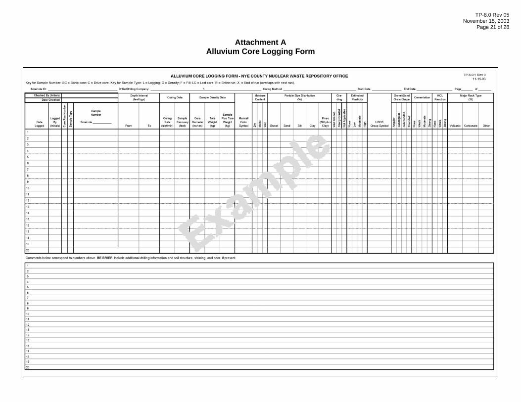
Before extruding the brass liners from the solid tube core barrel, NWRPO personnel shall perform the following tasks and record core run data on the Alluvium Core Logging Form (Attachment A) as a single entry.
1. Record the date the sample is logged and the initials of the logger.
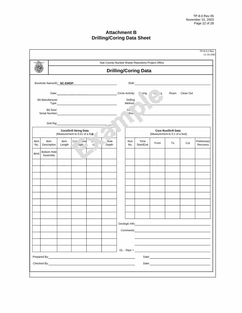
2. Record the core run number and the depth interval, using information from the Drilling/Coring Data Sheet (Attachment B). Note that the “To” depth on Attachment B will be the “From” depth plus either the length of the barrel plus shoe (i.e., when the core barrel is driven further than its own length) or the distance the barrel is driven (i.e., when the core barrel is driven less than its own length).
3. Record the sample type. Sample types include geologically logged core segments (L); samples designated for density measurements (D); the sample comprising the entire run before it is divided into subsamples (R); lost core (LC), and a sample composed of fill (i.e., previously disturbed material) (F). For this sample, record “RD” to designate the entire core run with density measurements.
TP-8.0 Rev 05 November 15, 2003
Page 5 of 28
4. Record the sample number, using a compilation of the borehole name, the depth interval, and whether the core is drive core (C) or sonic core (SC). For example, a drive core sample from borehole NC-EWDP-27P with a depth interval of 100.0 to 102.5 feet would be numbered 27P-100.0-102.5-C.
5. Measure and record the coring rate, in feet per minute, for the entire cored interval.
6. Make the following whole core bulk density measurements and record them in the appropriate columns:
a. Core diameter: determine the inside diameter of the core barrel liners.
b. Tare weight: enter the weight of the empty core barrel, plus the backhead, plus the shoe, plus liners, measured before beginning the core run.
c. Sample plus tare weight: weigh the full core barrel, plus backhead, plus shoe, plus liners upon completion of the core run.
7. Remove the backhead and shoe from the core barrel and determine the following core recovery measurements:
a. Measure the length of any void space at the top and bottom of the core barrel plus shoe and assume that this total void space length is equal to core loss. Subtract core loss from the “Cut” length (i.e., the “To” minus the “From” lengths) shown on Attachment B to determine the core length recovered (i.e., sample recovery).
b. At this time, also record the recovered core length as the preliminary recovery on the Drilling/Coring Data Sheet.
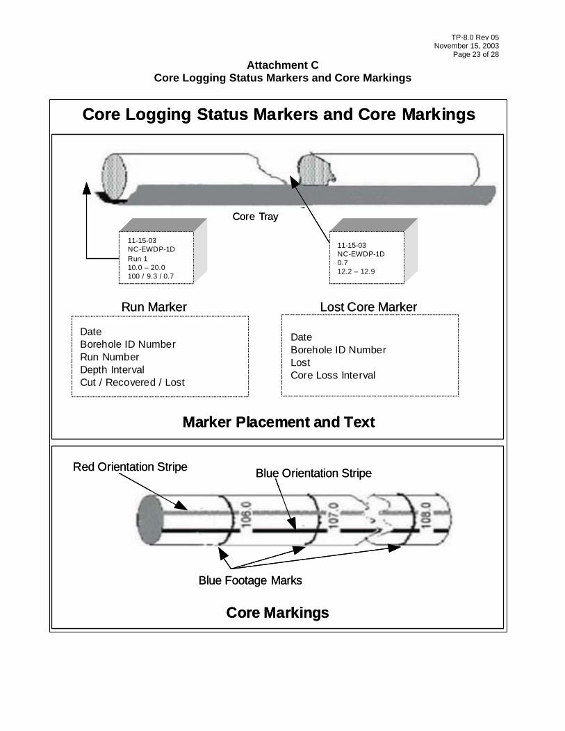
8. Using the measurements and calculations determined in the steps above, fill out the information on the polystyrene foam Run and Lost Core Markers shown on the Core Logging Status Markers and Core Markings Form (Attachment C). This information includes:
a. Date
b. Borehole ID.
c. Run number.
d. Depth interval.
e. Cut, recovered, and lost footage.
f. Core loss depth interval.
TP-8.0 Rev 05 November 15, 2003
Page 6 of 28
9. Place the Run Marker at the top of the core barrel and the Lost Core Marker(s) at the top and/or bottom of the core barrel plus shoe. Keep these markers in place during the core processing steps described in the following sections.
5.2.3 Core Segment Processing Tasks
NWRPO personnel shall carry out the following steps in a manner that minimizes evaporation and physical disturbance to the core segments.
1. Hydraulically extrude the 3- and 6-inch-long core liners from the solid tube core barrel onto a core tray or individual sample pans.
2. As specified in WP-8, immediately separate and package time-sensitive analytical samples (i.e., core segments that would suffer damage if left exposed to the atmosphere while awaiting processing). If samples are not time-sensitive, skip this step and proceed to Step 3.
a. Time-sensitive samples will be the exception rather than the rule. An example is a core segment designated for special (i.e., volatile organics) laboratory analysis.
b. Special packaging and handling, including labeling, sealing, and temporary storage requirements, for time-sensitive samples are specified in WP-8. In addition, these samples will not be geologically logged.
3. Label each core liner containing geologic material with the borehole ID and depth interval, using an indelible felt-tipped pen. In addition, denote the top and bottom of the core liners by using red and blue indelible felt-tipped pens to place parallel orientation stripes along each liner from end to end so that the red stripe is on the right when the liner is placed upright.
4. Separate core liners, using a large putty knife, in a manner that minimizes the disturbance of the top and bottom surfaces.
5. Using the large putty knife, flatten the top and bottom surfaces by removing sediment from high spots and adding this excess to low spots, compacting it at the same time.
6. While examining the liner and flattening liner surfaces, generate a geologic log of each segment using the steps described in the following section.
7. After geologic logging and the flattening of top and bottom surfaces, cover the surfaces with a tight-fitting plastic cap and tape the cap to the brass liner to provide an additional seal.
8. Label the top (i.e., uphole) end cap with the same information written on the liner (i.e., borehole ID and depth interval).
TP-8.0 Rev 05 November 15, 2003
Page 7 of 28
9. If a special airtight Protectore® wrap is available, seal each segment with this wrap. Label the additional wrap with the same information written on the brass liner and the top end cap (i.e., borehole ID and depth interval).
5.2.4 Drive Core Logging
NWRPO field personnel shall log, using visual manual methods, both ends of each 3- and 6-inch-long core segment. Physical and chemical logging parameters and the criteria for their description are based on ASTM D-2488-93, Standard Practice for the Description and Identification of Soils (Visual Manual Procedure).
NWRPO personnel shall perform the following tasks for each core segment and record the resulting data for each segment as a single entry on the Alluvium Core Logging Form (Attachment A).
1. Record the date the sample is logged and the initials of the logger.
2. Record the core run number and depth interval.
a. Record the depth interval from the liner if the liner is completely full of either core material from the formation or fill material.
b. If the liner is partially full of either core or fill, record the depth interval corresponding to the portion of the liner that is full.
c. If the liner contains both fill and core, make separate depth interval entries for the different materials. For each entry, include the date the sample is logged, the initials of the logger, and the core run number.
3. Record the sample type for each depth interval (i.e., “L” for geologically logged core, “LC” for lost core, or “F” for fill).
4. Record the sample number, using a compilation of the borehole name, the depth interval, and whether the core is drive core (C) or sonic core (SC).
5. Discard fill material Do not record additional data for “F” or “LC” samples on the Alluvium Core Logging Form. Continue as follows for “L” sample types.
6. Examine the compaction of core sediments in each liner and identify those that are poorly compacted and therefore likely to be disturbed further by handling in the field and in the laboratory.
a. Write “Poorly Compacted” on the label of these liners.
b. Also, note that these samples are poorly compacted in the comments section of the Alluvium Core Logging Form.
7. Determine and record the following geologic logging data for each core segment:
TP-8.0 Rev 05 November 15, 2003
Page 8 of 28
a. Munsell Color – Estimate the predominant Munsell color name and hue/chroma/value of each core segment. Samples should be moist when describing color.
b. Moisture Content – Estimate the water in each core segment as dry, moist, or wet, using criteria in Table 3 of ASTM D-2488-93.
c. Particle Size Distribution – Estimate the percentages of gravel, sand, and fines (i.e., silt plus clay) using the following criteria.
- Gravel particles pass a 3-inch (75-millimeter [mm]) sieve and are retained on a No. 4 (4.75-mm) sieve.
- Sand particles pass a No. 4 (4.75-mm) sieve and are retained on a No. 200 (0.075-mm) sieve.
- Clay particles pass a No. 200 (0.075-mm) sieve and exhibit plasticity (i.e., putty-like properties) over a range of water contents.
- Silt particles pass a No. 200 (0.075-mm) sieve but do not exhibit plasticity at any water content.
d. Gradation – Estimate only for soils with less than 15 percent fines (i.e., silt plus clay). A coarse-grained soil is well-graded if it contains a wide range of particle sizes and substantial amounts of intermediate particle sizes. It is poorly graded if it contains predominantly one particle size, or if it has a wide range of particle sizes with some intermediate sizes missing.
e. Plasticity – Estimate plasticity for soil material where medium sand and larger sized fractions have been removed using criteria in Table 11 of ASTM D-2488-93.
f. Unified Soil Classification System (USCS) Group Symbol – Determine the USCS group symbol for coarse-grained sediments based on particle size distribution, grading, and plasticity, using criteria in Table 2 of ASTM D-2488-93. Determine USCS group symbols for fine-grained soils using criteria in Table 1a of ASTM D-2488.
g. Grain Shape – Estimate the angularity of coarse-grained particles using criteria in Table 1 of ASTM D-2488-93.
h. HCl Reaction – Describe the reaction of HCl as none, weak, or strong, using criteria in Table 4 of ASTM D-2488-93.
i. Cementation – Describe the cementation of intact coarse-grained soils as weak, moderate, or strong, using criteria in Table 6 of ASTM D-2488-93.
j. Rock Type – Identify and estimate the percentage of major rock types in the coarse sand and/or gravel fraction. Describe other types of rock present in significant amounts in the comments section.
TP-8.0 Rev 05 November 15, 2003
Page 9 of 28
2. Describe additional geologic logging information for each core segment in the comments section. Examples of additional logging information include maximum clast diameter, typical degree of welding in tuffs, or typical alteration and/or weathering of tuff clasts and other rock types.
5.2.5 Drive Core Boxing
1. Store sufficient quantities of waxed cardboard core boxes to accommodate projected daily core recovery cycles at the drill site.
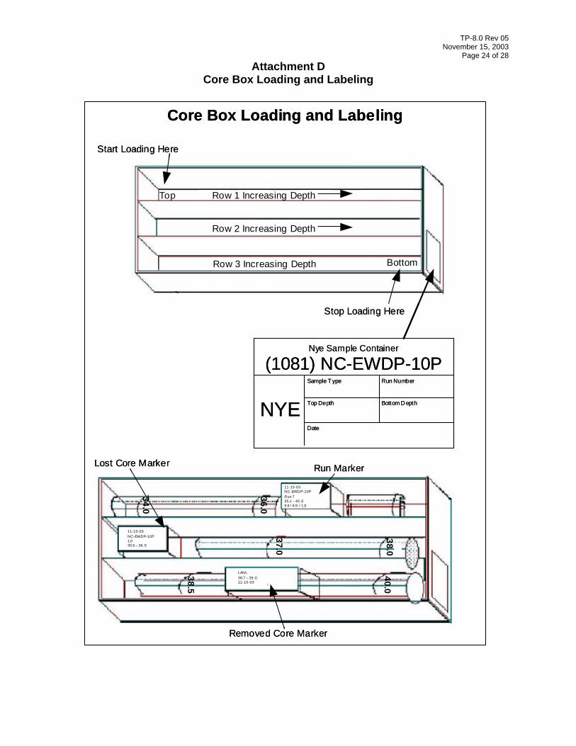
2. Place the core in the box with the top of the run in the upper left corner and the core orientation maintained as shown on the Core Box Loading and Labeling Form (Attachment D).
3. During the loading process, transfer all polystyrene foam Run and Lost Core Markers to their appropriate positions in the core box.
5.2.6 Drive Core Distribution
1. Refer to WP-8 or the appropriate TPN for core sample distribution instructions, including requestors and the core segments requested. The PI may make field changes to these distribution instructions to accommodate changing priorities. Changes shall be recorded in the field scientific notebook assigned to the relevant borehole.
2. Remove the specified core segment from the core box.
a. Place a polystyrene Removed Core Marker in place of the removed core as shown on Attachment D.
b. Write the requester, depth interval, and date on the marker.
3. Distribute core samples to requestors following chain-of-custody procedures.
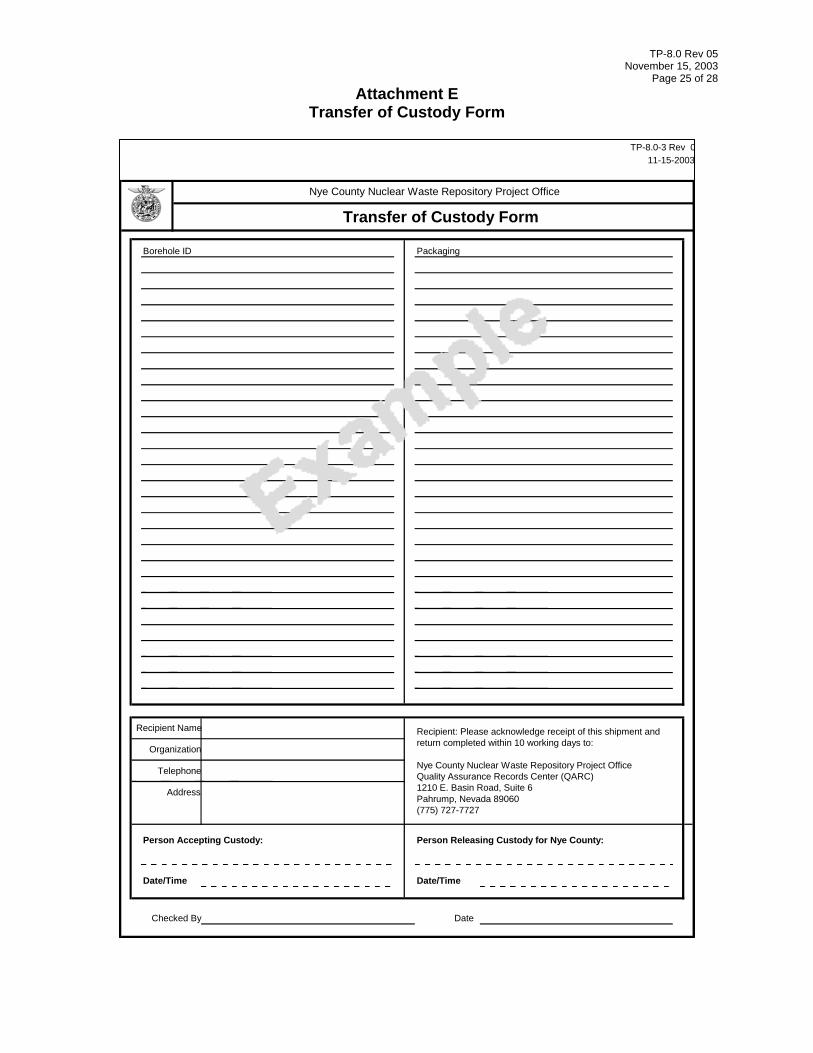
a. A Transfer of Custody Form (Attachment E) shall accompany distributed core samples.
b. The recipient shall sign the original form and return it to the NWRPO for inclusion in the QARC files.
4. Transfer Nye County core samples remaining in the Nye County core box to the Yucca Mountain Project (YMP) SMF following chain-of-custody procedures.
a. Fill out a Nye Sample Container label shown on the Core Box Loading and Labeling Form (Attachment D) and affix it to the outside of the box. Duplicate labels may be placed elsewhere inside and outside the box.
TP-8.0 Rev 05 November 15, 2003
Page 10 of 28
b. A Transfer of Custody Form shall accompany the core box to the YMP SMF for archiving.
5.3 Sonic Core Activities
The Driller shall collect sonic core in 10-foot runs where possible. In no cases will a run exceed 10 feet. In cases where refusal is met before the 10-foot depth is reached, one or more additional runs will be conducted to reach the target depth.
After a core run is brought to the ground surface, the driller shall transfer the core in approximately 2-foot lengths from the core barrel to polyethylene or equivalent tubes (i.e., plastic socks) with an ID approximately equal to the OD of the core barrel.
If more than one core run is required to meet the 10-foot target, the corehole shall be depth-sounded between runs to determine whether core has been left behind (i.e., lost core) and/or caving has occurred. Disturbed material shall be removed from the hole before the next core run. NWRPO field personnel shall determine whether disturbed material is lost core or caved formation material.
After each 10-foot interval has been cored, the drill casing shall be advanced to the bottom of the corehole. The core barrel shall then be used to clean out disturbed sediments before initiating a new core run.
5.3.1 Core Run Tasks and Measurements
NWRPO field personnel shall perform the following tasks for each core run and record the resulting data on the Alluvium Core Logging Form (Attachment A). The following measurements shall be recorded as a single entry on the Alluvium Core Logging Form.
1. Record the date the sample is logged and the initials of the logger.
2. Record the core run number and the depth interval, using information from the Drilling/Coring Data Sheet (Attachment B).
3. Record the sample type. For this sample, use “R” to designate the entire core run.
4. Record the sample number. For this sample, use “SC” at the end of the sample number to designate sonic core.
5. Measure and record the coring rate, in feet per minute, for the entire cored interval.
6. After completing Steps 4e and f in the following section, record the resulting sample recovery measurement.
TP-8.0 Rev 05 November 15, 2003
Page 11 of 28 5.3.2 Core Segment Tasks and Measurements
The following measurements shall be made for each approximately 2-foot long core segment in a plastic sock and recorded as a single entry for each segment on the Alluvium Core Logging Form.
1. Record the date the sample is logged and the initials of the logger.
2. Record the core run number, using information from the Drilling/Coring Data Sheet (Attachment B).
3. Record the sample type. Use “D” to designate density measurements.
4. Determine and record the depth interval for each segment and the sample recovery length for each core run as follows:
a. Place the core segments end to end in an approximately 5-foot-long PVC pipe, split lengthwise, with approximately the same ID as the core barrel OD. The split PVC pipe acts as a cradle for the core, helping to minimize additional mixing of cored material and making it easier to assign depth intervals to the segments.
b. Measure the length of each core segment and write this value on the uphole portion of the plastic sock with an indelible felt-tipped pen. This length will be referred to as the “uncorrected segment length.”
c. Add the uncorrected segment lengths of all core segments in the core run and write this value on the plastic sock of the downhole portion of the lowermost core segment using an indelible felt-tipped pen. This value will be referred to as the “uncorrected sample recovery length.”
d. Calculate and record the depth interval of each segment when measured void space in the bottom of the core barrel, measured disturbed material in the corehole, and/or measured core sample recovery meet the following criteria. In all other cases, determine the depth interval of each core segment as described in Step 4f.
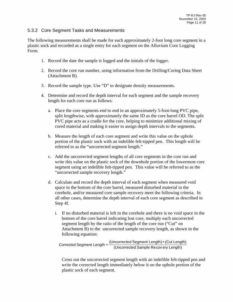
i. If no disturbed material is left in the corehole and there is no void space in the bottom of the core barrel indicating lost core, multiply each uncorrected segment length by the ratio of the length of the core run (“Cut” on Attachment B) to the uncorrected sample recovery length, as shown in the following equation:
)LengtherycovReSampledUncorrecte(
)LengthCut(×)LengthSegmentdUncorrecte(=LengthSegmentCorrected
Cross out the uncorrected segment length with an indelible felt-tipped pen and write the corrected length immediately below it on the uphole portion of the plastic sock of each segment.
TP-8.0 Rev 05 November 15, 2003
Page 12 of 28
Finally, determine and record depth intervals for each segment as follows. Beginning at the uppermost segment, add the corrected segment length to the “From” depth on Attachment B to calculate the “To” depth for this segment. Write these “From” and “To” values on the plastic sock below the corrected length value. The “To” depth of the first segment becomes the “From” depth of the second segment. Calculate the “To” depth of this second segment and record both “From” and “To” values as in the first segment. Repeat this process for each subsequent core segment in the core run. Finally, record the depth intervals for each core segment on Attachment A.
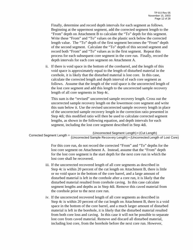
ii. If there is void space in the bottom of the corebarrel, and the length of this void space is approximately equal to the length of disturbed material in the corehole, it is likely that the disturbed material is lost core. In this case, calculate the corrected length and depth interval of each core segment as follows. Assume that the length of the void space is the uncorrected length of the lost core segment and add this length to the uncorrected sample recovery length of all core segments in Step 4c.
This sum is the “revised” uncorrected sample recovery length. Cross out the uncorrected sample recovery length on the lowermost core segment and write this sum below it. Use the revised uncorrected sample recovery length in place of the uncorrected sample recovery length in the correction ratio presented in Step 4di; this modified ratio will then be used to calculate corrected segment lengths, as shown in the following equation, and depth intervals for each segment, including the lost core segment described in Step 4di.
)CoreLostofLengthdUncorrecte(+)LengtherycovReSampledUncorrecte()LengthCut(×)LengthSegmentdUncorrecte(
=LengthSegmentCorrected
For this core run, do not record the corrected “From” and “To” depths for the lost core segment on Attachment A. Instead, assume that the “From” depth for the lost core segment is the start depth for the next core run in which the lost core shall be recovered.
iii. If the uncorrected recovered length of all core segments as described in Step 4c is within 20 percent of the cut length on Attachment B, there is little or no void space in the bottom of the core barrel, and a large amount of disturbed material is left in the corehole after a core run, it is likely that the disturbed material resulted from corehole caving. In this case calculate segment lengths and depths as in Step 4di. Remove this caved material from the corehole prior to the next core run.
iv. If the uncorrected recovered length of all core segments as described in Step 4c is within 20 percent of the cut length on Attachment B, there is a void space in the bottom of the core barrel, and a much larger amount of disturbed material is left in the borehole, it is likely that the disturbed material resulted from both core loss and caving. In this case it will not be possible to separate lost core from caved material. Remove and discard all disturbed material, including lost core, from the borehole before the next core run. However,
TP-8.0 Rev 05 November 15, 2003
Page 13 of 28
correct the segment lengths and depths using the approach described in Step 4dii. In this case, and all other cases where lost core is discarded, use “LC” to designate lost coreto the corresponding depth interval on Attachment A.
e. Calculate the true sample recovery length for each core run by summing up all corrected core segment lengths. Record this sum as the sample recovery value as described above in Section 5.3.1, Step 6d.
f. In scenarios other than those described in Step 4d, it will not be possible to distinguish lost core from disturbed material in the corehole, nor will it be possible to calculate corrected depths for core segments. In these cases, assign depths as follows.
i. If the uncorrected sample recovery length is less than the cut length, assign depths using a tape measure. Assume that lost core is equal to the cut length minus the recovery length, and assume the sample recovery value to be equal to the uncorrected sample recovery length.
ii. If the sample recovery length is greater then the cut length, the NWRPO and DOE contract geologist will jointly choose a consistent and logical approach to depth assignment.
5. Record the sample number, using the corrected depth interval. Use “SC” at the end of the sample number to designate sonic core.
6. Make the following density measurements for each segment and record them as follows.
a. Weigh each segment in its plastic sock and record it as the sample plus tare weight.
b. Assume that the tare weight of each sock is approximately 0.1 kilograms (kg) and that the core diameter is approximately equal to the OD of the core barrel.
7. Photograph each core run as follows, using a digital camera.
a. Slit the plastic sock of each core segment in the cradle lengthwise and expose approximately one-third of the core surface.
b. Photograph the exposed surface of each segment. Include the core run number and corrected depth interval information in the photographs.
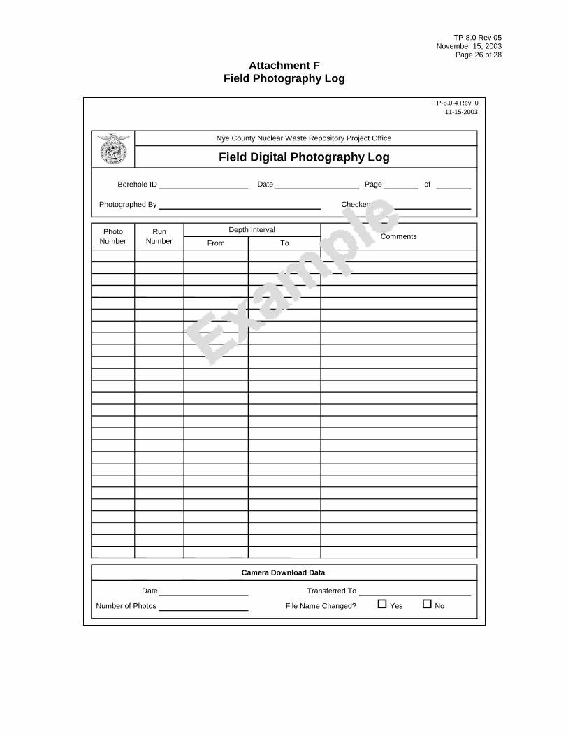
c. Fill out Field Digital Photography Log (Attachment F).
5.3.3 Sonic Core Logging
With the entire core run in the cradle(s), NWRPO field personnel shall identify the boundaries between layers with noticeably different particle sizes using visual manual logging methods. Adjacent core runs shall be logged at the same time to identify layers that overlap core runs.
TP-8.0 Rev 05 November 15, 2003
Page 14 of 28 Layer thicknesses may range from less than an inch to tens of feet. Logging methods shall be based on ASTM D-2488-93.
After boundaries of distinct layers have been clearly marked on the plastic sock with an indelible felt-tipped pen, NWRPO field personnel shall fill out the Alluvium Core Logging Form (Attachment A) as follows, using a single entry for each layer.
1. Record the date the sample is logged and the initials of the logger.
2. Record the core run number using information from the Drilling/Coring Data Sheet (Attachment B).
3. Record the sample type. For this sample, record “L” to designate a geologically logged core segment.
4. Determine and record the depth interval for each layer.
a. Measure the uncorrected length of each layer. Calculate the corrected lengths and depths using the methods described in Section 5.3.2, Step 4. If a layer overlaps more than one core run, use the appropriate run-specific correction factor.
b. Record the corrected depth interval adjacent to the boundary mark on the plastic sock and the Alluvium Core Logging Form.
5. Record the sample number, adding SC at the end to designate sonic core. Before recording the number, check the existing sample numbers for duplicates. If a duplicate exists, add SCa instead of SC so that the sample number will be unique.
6. Scrape a small portion (e.g. approximately one-fourth to one-twentieth) from the upper exposed surface from each identified layer. Scrape at least 1 to 2 liters, where possible. If it is not possible to obtain a representative sample by scraping, collect one or more vertical slices. Homogenize and split the collected core material into three NWRPO subsamples: one for more detailed field geologic logging, one for laboratory measurements, and one for archival at the SMF.
If the layer length is short and the volume of sample small, the split for archival at the SMF does not need to be collected. If the volume of the sample is very small, use the same material for both detailed field logging and laboratory testing. If one or more splits are not collected, note this in the comments section.
If core material is scraped from the exposed upper surface of the layer, fill out a Removed Core Marker for each layer. Record the depth interval of the entire layer with the estimated percentage removed and place each marker at the beginning of the core run.
If one or more vertical slices are removed, fill out and place the marker as described in Section 5.2.6.
TP-8.0 Rev 05 November 15, 2003
Page 15 of 28
7. Determine and record the same geologic logging parameters as drive core (Section 5.2.4) on the split designated for detailed logging.
8. Transfer of Custody Forms (Attachment E) shall accompany the testing split, which shall be shipped to the NWRPO laboratory and the archival splits, which shall be shipped to the SMF.
9. If a sample is removed from each layer by scraping, take final photographs of each core segment, focusing on the scraped surface where the interior of the core has been exposed.
a. Photograph the exposed surface of each segment and each layer with distinct particle size differences. Include the core run number and segment depth interval information in the photographs.
b. Fill out Field Digital Photography Log (Attachment F).
i. On a daily basis, download data from the digital camera. Assign file names as follows: ooooyymmdd999, where oooo is the borehole ID, yy is the last two digits of the year, mm is the month, dd is the day of the month, and 999 is the photo number (e.g., 29P031115001).
ii. Once a week, transfer the photographic images to electronic storage media (i.e., Zip disk or CD) for submission to the NWRPO QARC.
5.3.4 Sonic Core Distribution
1. Fill out a Transfer of Custody Form (Attachment E) and transfer the core to DOE geologists, who will package, label, box, transport, and archive the core according to standard DOE practices.
2. DOE geologists will carry out these tasks in a manner that maintains layering and minimizes sediment mixing.
5.4 Drill Cuttings Activities
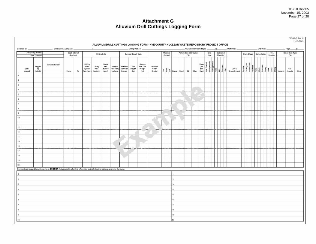
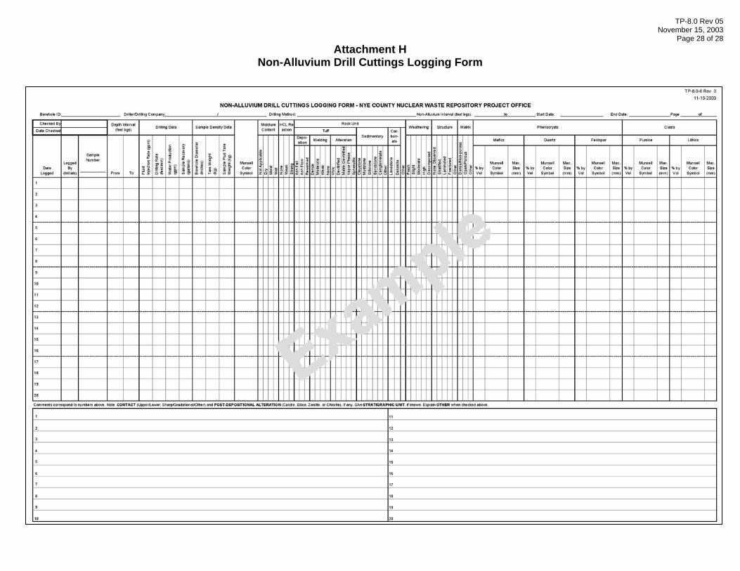
Drill cuttings data are recorded on the Alluvium Drill Cuttings Logging Form (Attachment G) and the Non-Alluvium Drill Cuttings Logging Form (Attachment H).
5.4.1 Drill Cuttings Collection
The processing and logging procedures described in the following sections have been designed under the assumption that appropriate drilling methods have been selected to yield samples that are as representative as reasonably possible of in situ formation rocks. Drilling methods applicable to the EWDP drilling phase of interest are presented in WP-5 and/or associated TPNs.
Although drill cuttings are considered more disturbed from in situ formation conditions than core samples, some drilling methods, in some rock types, can yield cuttings samples that are approximately representative of in situ conditions. Examples of drilling methods and the
TP-8.0 Rev 05 November 15, 2003
Page 16 of 28 representative properties/conditions, or lack thereof, of the resulting drill cuttings include the following:
1. In unsaturated alluvium, only a limited number of drilling methods (e.g., reverse air rotary and casing advance drilling methods) produce drill cuttings samples with particle size distributions that are approximately representative of in situ conditions.
2. These methods can also yield samples with representative particle size distributions in the upper region of saturated alluvium not producing significant amounts of water.
3. No drilling methods are known to consistently produce drill cutting samples with representative particle size distributions from regions of saturated alluvium that produces significant amounts of water during drilling.
4. Many drilling methods in most non-alluvium rock types and in both saturated and unsaturated zones are known to produce drill cuttings samples of sufficient quality to permit the identification of minerals and rock types.
5.4.2 Preliminary Sample Processing
Methods for splitting and homogenizing alluvium drill cuttings collected from the unsaturated zone, and from the upper portion of the saturated zone that does not produce a significant amount of water, are presented in WP-8 and/or in applicable TPNs. Systematic sample splitting and homogenization shall be done to maximize the usefulness particle size distribution data from these samples
1. Sieve and wash splits of non-alluvium drill cuttings designated for geologic logging from both the unsaturated and saturated zones to remove the silt and clay fraction, which will facilitate mineralogical description and the identification of rock types.
2. Place the following drill cuttings splits in muffin pans for geologic logging of unsieved/unwashed alluvium samples from both the unsaturated and saturated zones and sieved/washed samples of non-alluvium from both the unsaturated and saturated zones.
3. Place subsamples of the splits placed in muffin pans for logging in plastic trays for future reference.
4. If a sample was not collected due to loss of circulation or for any other reason, place a marker in the space left by the lost sample to preserve sample continuity.
5.4.3 Drilling Data and Sample Density Measurements
The following drilling and bulk density measurements shall be made for each depth interval sampled. This interval is generally 2.5 feet in unsaturated alluvium and 5 feet in saturated alluvium and both saturated and unsaturated non-alluvium. The following information shall be recorded on the appropriate Drill Cuttings Logging Form (Attachments G or H) as appropriate.
TP-8.0 Rev 05 November 15, 2003
Page 17 of 28
1. Record the date the sample is logged and the initials of the logger.
2. Record the sample number. Drill cuttings sample numbers will be comprised only of the borehole ID and depth interval.
3. Record the 2.5- or 5-foot depth interval.
4. Record the following drilling data for each depth interval:
a. Drilling fluid injection rate (gallons per minute [gpm]) – Calculate using the bucket and stopwatch method for every second length of drill rod or drill casing and more frequently if injection rates are adjusted due to formation changes.
b. Drilling rate (foot/minute) – Calculate from the time to advance (i.e., drill) the length of the drill rod or drill casing, excluding any time needed for clean out or hole conditioning.
c. Water production (gpm) - Air lift the borehole and calculate using the bucket and stopwatch method after drilling every second length of drill rod or drill casing, unless air is not being used as the primary circulation fluid.
d. Sample recovery (gallons) – Calculate from the number of buckets, or volume within buckets, required to contain drill cuttings collected from every depth interval sampled. If a splitter system is used within the sample return system (e.g., Ananconda® wet splitter), record the splitter ratio on the form in the comments section so that the total sample volume can be back-calculated.
5. Record the following sample density data for each sample only when drilling with casing advance drilling methods. In all other cases, do not record sample density measurements.
a. Borehole diameter – Determine the diameter of the borehole, assuming that it is equal to the drill bit diameter.
b. Tare weight – Weigh the empty buckets used to collect the drill cuttings samples for the drilled interval and hole cleaning operations.
c. Sample plus tare weight - Weigh the buckets containing the drill cuttings collected for the drilled sample interval and hole cleaning operations conducted at the end of the drill run. Add the weight of these clean-out cuttings to the weight of the cuttings from the last depth interval sampled.
5.4.4 Logging of Alluvium Drill Cuttings
Alluvium drill cuttings shall be geologically logged using the methods described for drive and sonic core. The logging data shall be recorded on the Alluvium Drill Cuttings Logging Form (Attachment G) as a continuation of the single entry for each sample interval as described in
TP-8.0 Rev 05 November 15, 2003
Page 18 of 28 Section 5.4.3. The following additional requirements apply when logging alluvium drill cuttings:
1. Do not record particle size distributions for alluvium samples collected below the water table in regions that produce significant amounts of water (e.g., less than 1 gpm). Particle size distributions in these samples are not representative of in situ conditions.
2. Record moisture content for drill cuttings produced using only compressed air as the drilling fluid in the unsaturated zone and the upper region of the saturated zone not producing significant amounts of water.
3. Relatively large, intact pieces of the sample are necessary to accurately describe the degree of cementation. Record cementation data only when such pieces are available.
5.4.5 Logging of Non-Alluvium Drill Cuttings
Non-alluvium drill cuttings shall be geologically logged and the data shall be recorded on the Non-Alluvium Drill Cuttings Logging Form (Attachment H) as a continuation of the single entry for each sample interval as described in Section 5.4.3. The following logging data shall be recorded for non-alluvium drill cuttings:
1. Rock unit – The following major rock units may be present beneath alluvium in the region targeted by the EWDP: volcanic tuffs, sedimentary rocks, and carbonate rocks. Tuffs are further subdivided by depositional mode, degree of welding, and alteration. Types of sedimentary rocks include claystone, mudstone, siltstone, sandstone, conglomerate, and chert. Types of carbonate rocks include limestone and dolomite. Describe other types of rock in the comments section.
2. Alteration – Rocks may undergo mineralogical alteration. Possible alteration products include calcite, silica, zeolite, chlorite, and other mineral types. Describe other mineral types in the comments section.
3. Weathering – Examine natural rock surfaces and fractures, and select one of the following descriptors: fresh, slightly weathered, moderately weathered, highly weathered, or decomposed. Fresh refers to cuttings where natural surfaces show no evidence of oxidation, discoloration, separation of grains, change in texture, or dissolution. Slightly weathered describes natural surfaces that show some evidence of oxidation and discoloration, dull feldspars, and minor leaching, but no separation of grains. Moderately weathered indicates that natural surfaces are mostly discolored or oxidized, grains are partially separated, crystals are rusty or cloudy, and there is evidence of moderate leaching of soluble minerals. Highly weathered indicates total discoloration or oxidation of natural surfaces, extensive clay alteration and grain separation, complete leaching, and that the rock is friable. Decomposed refers to consolidated rock where grain separation and clay alteration are complete.
4. Structure – Examine intact pieces of rock, if present, for bedding and natural fractures. Stratified structure describes bedding where layers are at least 6 millimeters
TP-8.0 Rev 05 November 15, 2003
Page 19 of 28
(mm) thick; the actual thickness should be noted in the comments section. Laminated structure describes bedding less than 6 mm thick; again, the actual thickness should be noted in the comments section. Fractured structure describes the presence of natural breaks along planes of weakness.
5. Matrix porosity – Describe the relative porosity of the rock matrix as porous, non-porous, or other. Describe other porosity in the comments section.
6. Phenocrysts and clasts – Examine intact pieces of rock, if present, for the presence of phenocrysts and clasts. Record the percent by volume, color, and maximum size of these features. In addition, to the extent possible, include the degree of pumice flattening in the comments section.
7. Use the comments section for additional geologic descriptive information for each sample.
5.4.6 Drill Cuttings Distribution
Cuttings samples shall normally be split into at least two portions per sampled interval, but may be further subdivided. WP-8 and/or related TPNs provide instructions regarding sample splitting and distribution to different users. NWRPO field personnel shall place a sufficient quantity of representative cuttings in sample bags; alternative containers, such as bottles, are also acceptable. The bag shall be labeled using indelible felt-tipped pen with the following information: borehole ID, sample depth interval, and date sampled.
Cuttings samples shall be maintained under chain of custody at all times, either in view of the current holder or secured in locked storage. The distribution of splits of cuttings to authorized recipients shall be accompanied by a completed Transfer of Custody Form (Attachment E). The recipient shall sign the original form and return it to the NWRPO for inclusion in the QARC files.
6.0 DATA ACQUISITION METHODOLOGY AND LIMITATIONS
Geologic data acquired from the logging of borehole samples shall be descriptive geologic terms tied to specific physical locations at depth in a drilled borehole. Drilling-related logging measurements shall be similarly tied to a borehole and depth. It is possible that these field data and the additional laboratory testing data derived from these samples will be used during U.S. Nuclear Regulatory Commission proceedings to evaluate the DOE license application.
Logging data shall be recorded on forms by NWRPO field personnel, who will sign off as recorders. These data shall be independently reviewed by NWRPO field personnel trained to this procedure, and the review shall be verified by the reviewer's signature on forms.
Uncertainty attached to the methodology in the acquisition of geologic data from borehole samples includes the variability of the level of skill of the NWRPO field personnel performing the logging and individual professional judgment. Completed forms shall be submitted to the NWRPO QARC approximately once a week for capture and preservation in the project files.
TP-8.0 Rev 05 November 15, 2003
Page 20 of 28 7.0 REFERENCES
ASTM D-2488-93. Standard Practice for the Description and Identification of Soils (Visual Manual Procedure). In: 1996 Annual Book of ASTM Standards, Vol.04.08, American Society for Testing and Materials.
EWDP Health and Safety Plan.
QAP-3.2, Procedures for Documentation of Scientific Investigations.
TP-7.0, Drill Site Management.
WP-5, Early Warning Drilling Program Drilling and Well Construction Work Plan
WP-8, Sample Management Plan for EWDP
8.0 RECORDS
Alluvium Core Logging Form
Drilling/Coring Data Sheet
Transfer of Custody Form
Field Photography Log
Alluvium Drill Cuttings Logging Form
Non-Alluvium Drill Cuttings Logging Form
9.0 ATTACHMENTS
A. Alluvium Core Logging Form
B. Drilling/Coring Data Sheet
C. Core Logging Status Markers and Core Markings
D. Core Box Loading and Labeling
E. Transfer of Custody Form
F. Field Photography Log
G. Alluvium Drill Cuttings Logging Form
H Non-Alluvium Drill Cuttings Logging Form
TP-8.0 Rev 05 November 15, 2003
Page 21 of 28
Attachment A Alluvium Core Logging Form
TP-8.0 Rev 05 November 15, 2003
Page 22 of 28
Attachment B Drilling/Coring Data Sheet
Clean Out
Item No. Cut Preliminary
Recovery
BHA
Date:
Date:
TP-8.0-2 Rev
NC-EWDP-
Coring Drilling Ream
Item Length
Cumulative Length
Stick Up
Hole Depth
Run No.
Time Start/End From To
011-15-2003
Checked By:
Borehole Name/ID:
Date: Bit Manufacture/
Type: Bit Size/
Serial Number:
Drill Rig:
Bottom Hole Assembly
GL - Slips =
Geologic Info:
Comments:
(Mill Data
ent to 0.1 of a foot) Item
Description
Drilling/Coring Data
Nye County Nuclear Waste Repository Project Office
Prepared By:
Coring Method:
Core/Drill String Data easurement to 0.01 of a foot )
Core Run/Dr(Measurem
Shift:
Circle Activity:
Drilling Method:
TP-8.0 Rev 05 November 15, 2003
Page 23 of 28 Attachment C
Core Logging Status Markers and Core Markings
Marker Placement and Text
Red Orientation Stripe Blue Orientation Stripe
Blue Footage Marks
Core Markings
Core Logging Status Markers and Core Markings
DateBorehole ID NumberRun NumberDepth IntervalCut / Recovered / Lost
DateBorehole ID NumberLostCore Loss Interval
11-15-03NC-EWDP-1DRun 110.0 – 20.0100 / 9.3 / 0.7
Run Marker Lost Core Marker
Core Tray
11-15-03NC-EWDP-1DRun 110.0 – 20.0100 / 9.3 / 0.7
11-15-03NC-EWDP-1D0.712.2 – 12.9
TP-8.0 Rev 05 November 15, 2003
Page 24 of 28 Attachment D
Core Box Loading and Labeling
Start Loading Here
Bottom
Top Row 1 Increasing Depth
Row 2 Increasing Depth
Row 3 Increasing Depth
Stop Loading Here
Nye Sample Container
(1081) NC-EWDP-10PSample T ype
Top Depth
Run Number
Bottom D epth
Date
NYE
Run MarkerLost Core Marker
Removed Core Marker
11-15-03NC-EWDP-10PRun 735.1 – 45 .09.9 / 8.9 / 1.0
11-15-03NC-EWDP-10P1.035.5 – 36 .5
LANL38.7 – 39 .011-15-03
34.0
36.0
37.0
38.5
40.038.0
Core Box Loading and Labeling
TP-8.0 Rev 05 November 15, 2003
Page 25 of 28 Attachment E
Transfer of Custody Form
Borehole ID
Person Accepting Custody:
Date/Time Date/Time
Checked By Date
TP-8.0-3 Rev
Packaging
011-15-2003
Person Releasing Custody for Nye County:
Address
Recipient: Please acknowledge receipt of this shipment and return completed within 10 working days to: Nye County Nuclear Waste Repository Project Office Quality Assurance Records Center (QARC) 1210 E. Basin Road, Suite 6Pahrump, Nevada 89060(775) 727-7727
Telephone
Nye County Nuclear Waste Repository Project Office
Transfer of Custody Form
Recipient Name Organization
TP-8.0 Rev 05 November 15, 2003
Page 26 of 28 Attachment F
Field Photography Log
of
TP-8.0-4 Rev 011-15-2003
Borehole ID
Nye County Nuclear Waste Repository Project Office
Photographed By
Photo Number Num
Date Number of Photos Yes
Transferred To
File Name Changed?
Camera Download Data
No
Date Page
Field Digital Photography Log
Comments Depth Interval
From ToRun
ber
Checked By
TP-8.0 Rev 05 November 15, 2003
Page 27 of 28 Attachment G
Alluvium Drill Cuttings Logging Form
TP-8.0 Rev 05 November 15, 2003
Page 28 of 28 Attachment H
Non-Alluvium Drill Cuttings Logging Form