Embed Size (px)
Citation preview
Field Based Methods
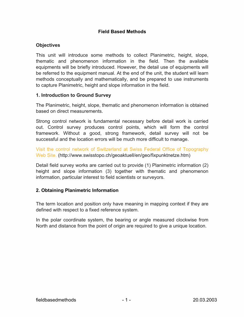
Objectives
This unit will introduce some methods to collect Planimetric, height, slope, thematic and phenomenon information in the field. Then the available equipments will be briefly introduced. However, the detail use of equipments will be referred to the equipment manual. At the end of the unit, the student will learn methods conceptually and mathematically, and be prepared to use instruments to capture Planimetric, height and slope information in the field.
1. Introduction to Ground Survey
The Planimetric, height, slope, thematic and phenomenon information is obtained based on direct measurements.
Strong control network is fundamental necessary before detail work is carried out. Control survey produces control points, which will form the control framework. Without a good, strong framework, detail survey will not be successful and the location errors will be much more difficult to manage.
Visit the control network of Switzerland at Swiss Federal Office of Topography Web Site. (http://www.swisstopo.ch/geoaktuell/en/geo/fixpunktnetze.htm)
Detail field survey works are carried out to provide (1) Planimetric information (2) height and slope information (3) together with thematic and phenomenon information, particular interest to field scientists or surveyors. 2. Obtaining Planimetric Information The term location and position only have meaning in mapping context if they are defined with respect to a fixed reference system.
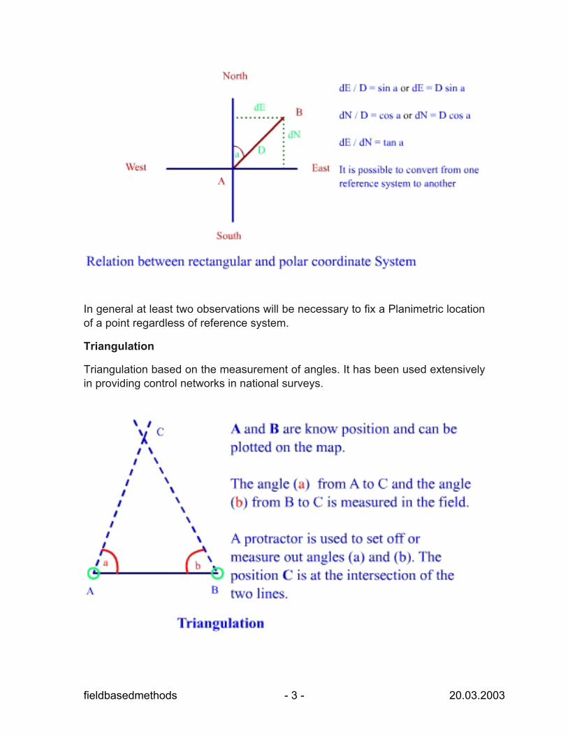
In the polar coordinate system, the bearing or angle measured clockwise from North and distance from the point of origin are required to give a unique location.
fieldbasedmethods - 1 - 20.03.2003
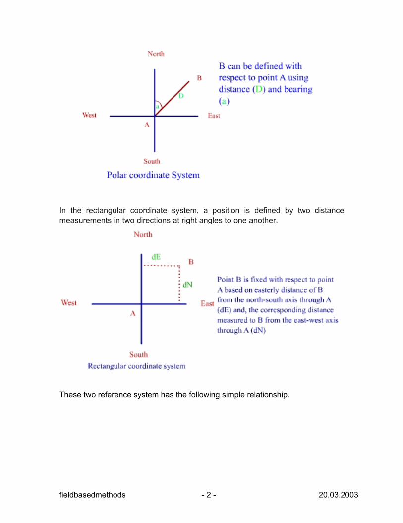
In the rectangular coordinate system, a position is defined by two distance measurements in two directions at right angles to one another.
These two reference system has the following simple relationship.
fieldbasedmethods - 2 - 20.03.2003
In general at least two observations will be necessary to fix a Planimetric location of a point regardless of reference system.
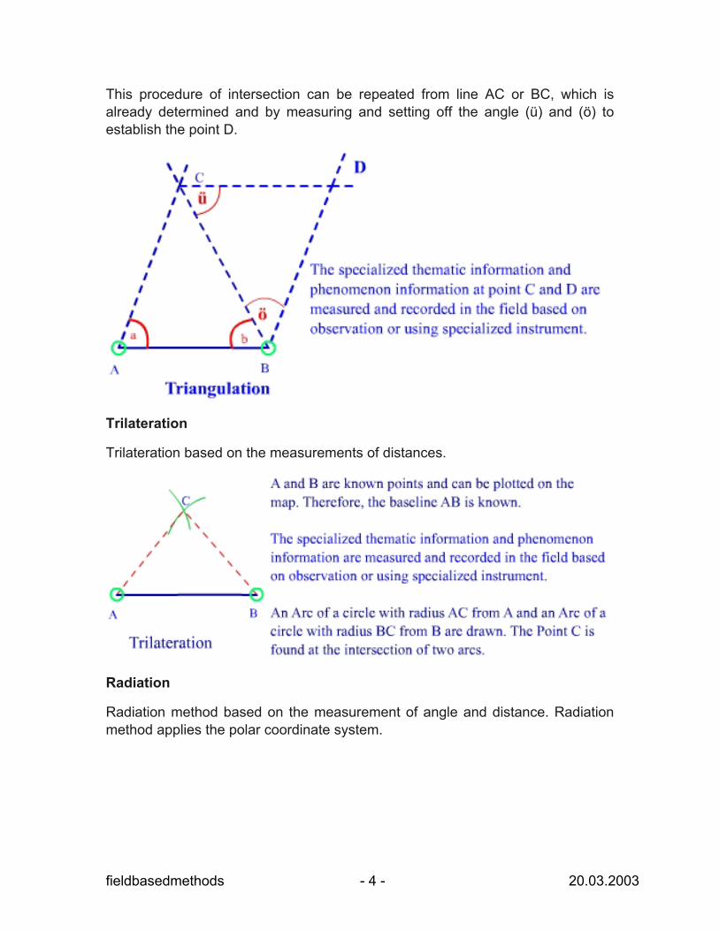
Triangulation
Triangulation based on the measurement of angles. It has been used extensively in providing control networks in national surveys.
fieldbasedmethods - 3 - 20.03.2003
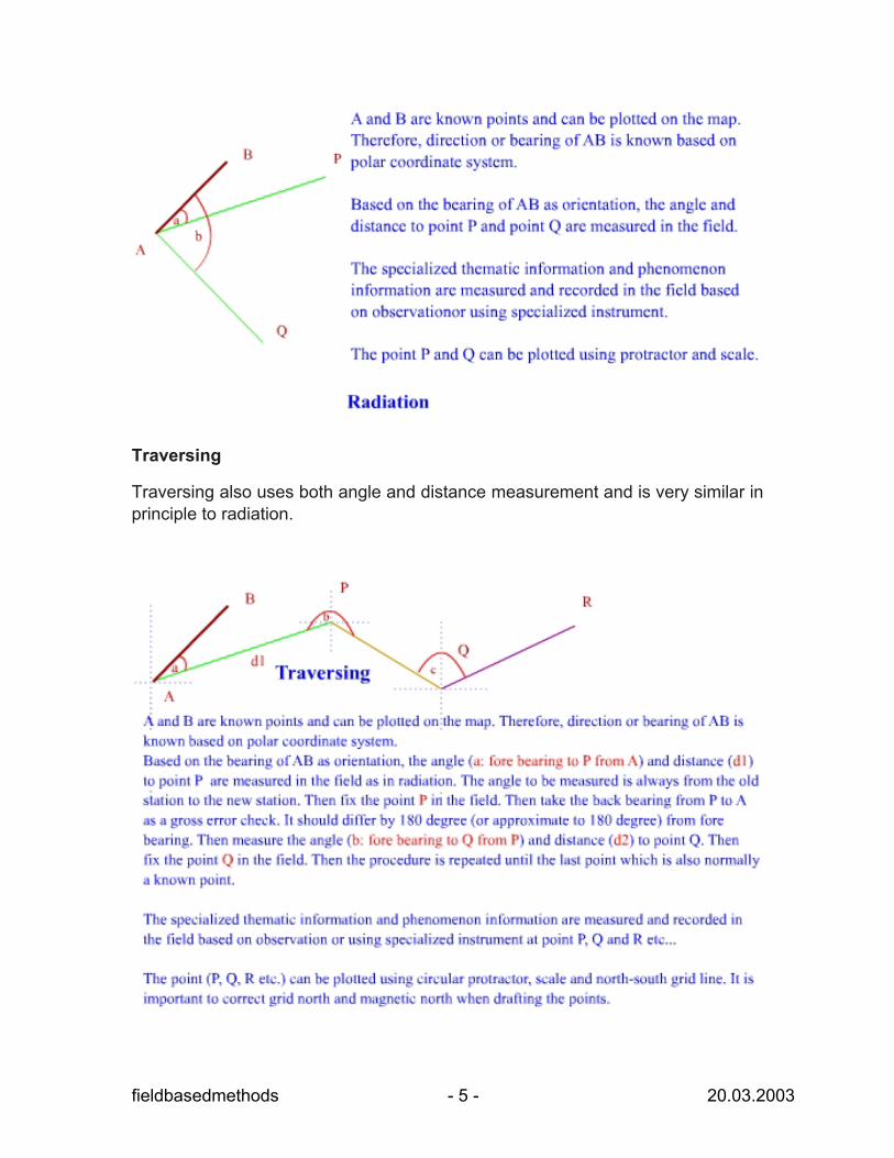
This procedure of intersection can be repeated from line AC or BC, which is already determined and by measuring and setting off the angle (ü) and (ö) to establish the point D.
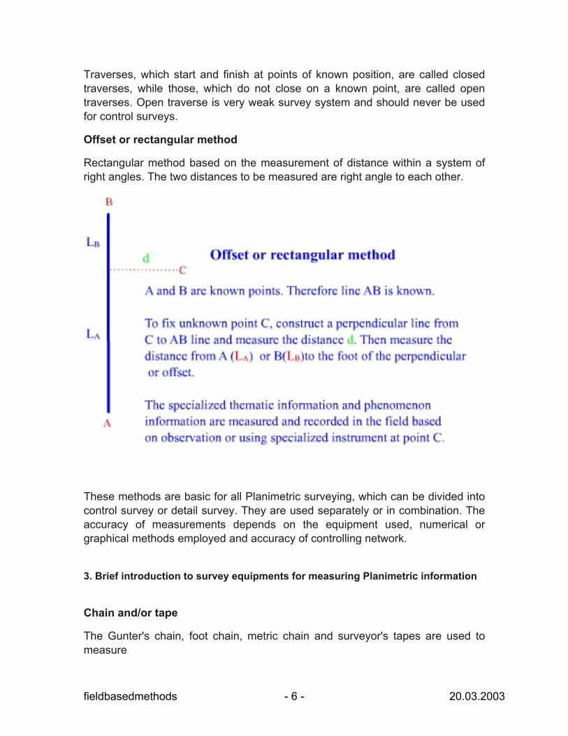
Trilateration
Trilateration based on the measurements of distances.
Radiation
Radiation method based on the measurement of angle and distance. Radiation method applies the polar coordinate system.
fieldbasedmethods - 4 - 20.03.2003
Traversing
Traversing also uses both angle and distance measurement and is very similar in principle to radiation.
fieldbasedmethods - 5 - 20.03.2003
Traverses, which start and finish at points of known position, are called closed traverses, while those, which do not close on a known point, are called open traverses. Open traverse is very weak survey system and should never be used for control surveys.
Offset or rectangular method
Rectangular method based on the measurement of distance within a system of right angles. The two distances to be measured are right angle to each other.
These methods are basic for all Planimetric surveying, which can be divided into control survey or detail survey. They are used separately or in combination. The accuracy of measurements depends on the equipment used, numerical or graphical methods employed and accuracy of controlling network.
3. Brief introduction to survey equipments for measuring Planimetric information
Chain and/or tape
The Gunter's chain, foot chain, metric chain and surveyor's tapes are used to measure
fieldbasedmethods - 6 - 20.03.2003
- the straight horizontal lines in flat and - the straight horizontal lines in non-flat terrains
by using the trilateration and offset methods.
The Gunter's chain is 66 ft in length and is divided into 100 parts known as link. The 100-foot chain and the metric chain (either 20 m or 30 m) are more common. The 100-foot chain is divided into 100 links. Therefore each link is 1 ft. In metric chain, each link is 200 mm.
The chain survey is suitable to survey a small area at a fairly large scale for the purpose of sampling or monitoring changes. Refer to the equipment manual for detail use.
Visit the following link for more information on Chain. (http://www.orbitals.com/self/survey/chain/chain.html)
Plane Table
The Plane Table is used to measure the angles by triangulation method for establishment of control networks or fixing a few points of detail over long distances especially to map greater than 1:2500 scale.
For the large-scale survey, plane table can be used to establish close detail by using the method of radiation, which is based on the measurement of angles and distance. In such application, the distance is measured by chain or tape and angle is measured by the plane table.
Traversing, which uses both angle and distance measurement, is suitable for control surveys where measurement along the line is required. The detail surveying can be carried out by radiation, intersection or offsets from the traverse control stations. Traversing with compass and chain can supplement control establishment by traversing with plane table especially in areas (where all-round vision is restricted and having problems connected with the formation of triangles with good intersection angles) causing difficulty for triangulation.
Refer to the equipment manual for detail use.
Visit the site for more information on Plane table.
http://uregina.ca/~sauchyn/geog411/mapping.html
Compass and chain
Traversing with compass and chain can be carried out to measure angles or bearing with a surveyor compass or a prismatic compass and distances with a surveyor’s chain or tape. This method can supplement control establishment with
fieldbasedmethods - 7 - 20.03.2003
plane table especially in areas where all -round vision is restricted and causing difficulty for triangulation.
Visit the following page to view the prismatic compass.
http://www.stanleylondon.com/comprism.htm
Refer to the equipment manual for detail use.
Theodolites
Visit the following page to view the surveyor compass
http://www.stanleylondon.com/compsurv.htm
Theodolites are most extensively used of all survey equipments. All theodolites are designed to perform two simple operations, namely to measure angles in horizontal and vertical planes.
Measurement of horizontal angles is applied for a triangulation scheme, for intersection ( method of fixing in which angular observations are taken at known points to fix the position of unknown points), for resection (method of fixing in which angular observations are taken at an unknown point to at least three known points whose positions are already or can be mapped), for radiation method and for traverse method. Plane table can be replaced by theodolites.
Radiation using theodolites and tape can be very efficient method of producing a detailed survey at a large scale.
A theodolite can be used to set out lines at right angles very readily.
Visit to the following link for more information on Theodolites equipment.
http://www.theodolite.com/
http://www.stanleylondon.com/theod.htm
Refer to the equipment manual for detail use.
4. Obtaining Height and Slope Information
The gradient of a slope, the relative height of a point to another, the absolute height of a point and the vertical dimension of an object are several forms of following triangular situation.
fieldbasedmethods - 8 - 20.03.2003
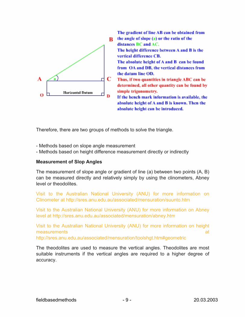
Therefore, there are two groups of methods to solve the triangle.
- Methods based on slope angle measurement - Methods based on height difference measurement directly or indirectly
Measurement of Slop Angles
The measurement of slope angle or gradient of line (a) between two points (A, B) can be measured directly and relatively simply by using the clinometers, Abney level or theodolites.
Visit to the Australian National University (ANU) for more information on Clinometer at http://sres.anu.edu.au/associated/mensuration/suunto.htm
Visit to the Australian National University (ANU) for more information on Abney level at http://sres.anu.edu.au/associated/mensuration/abney.htm
Visit to the Australian National University (ANU) for more information on height measurements at http://sres.anu.edu.au/associated/mensuration/toolshgt.htm#geometric
The theodolites are used to measure the vertical angles. Theodolites are most suitable instruments if the vertical angles are required to a higher degree of accuracy.
fieldbasedmethods - 9 - 20.03.2003
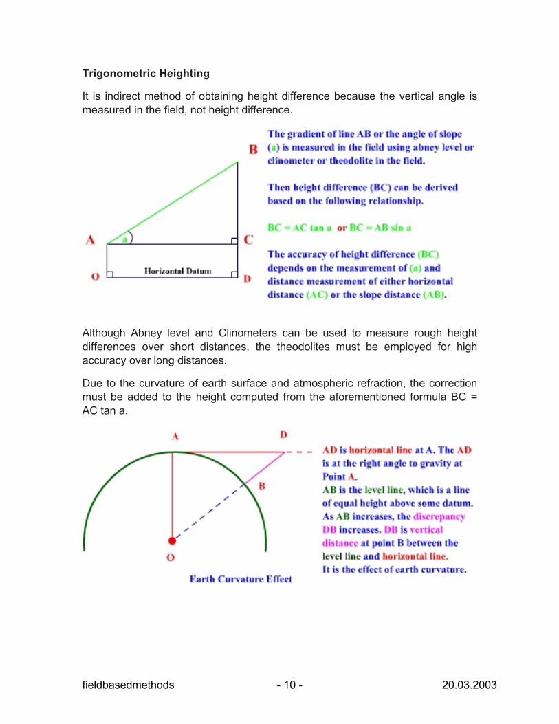
Trigonometric Heighting
It is indirect method of obtaining height difference because the vertical angle is measured in the field, not height difference.
Although Abney level and Clinometers can be used to measure rough height differences over short distances, the theodolites must be employed for high accuracy over long distances.
Due to the curvature of earth surface and atmospheric refraction, the correction must be added to the height computed from the aforementioned formula BC = AC tan a.
fieldbasedmethods - 10 - 20.03.2003
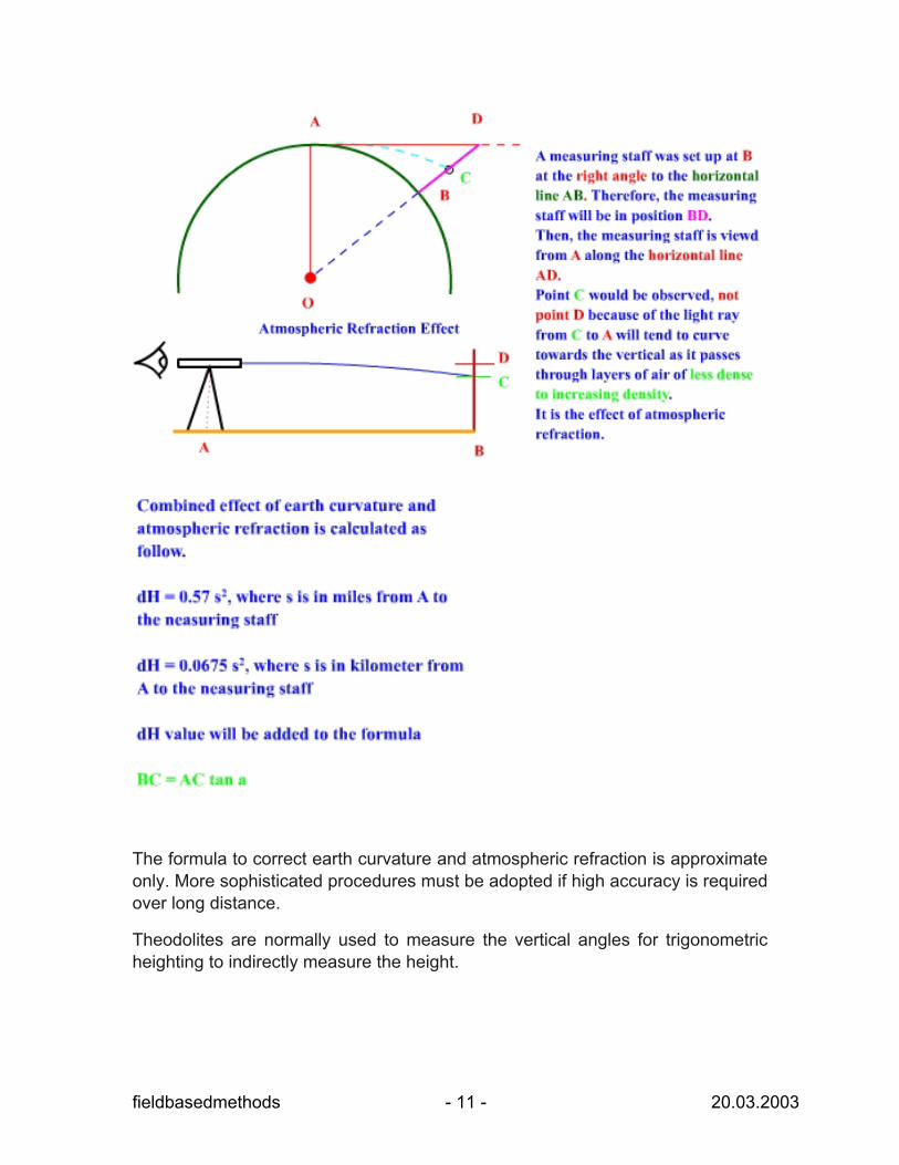
The formula to correct earth curvature and atmospheric refraction is approximate only. More sophisticated procedures must be adopted if high accuracy is required over long distance.
Theodolites are normally used to measure the vertical angles for trigonometric heighting to indirectly measure the height.
fieldbasedmethods - 11 - 20.03.2003
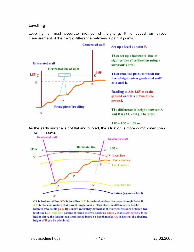
Levelling
Levelling is most accurate method of heighting. It is based on direct measurement of the height difference between a pair of points.
As the earth surface is not flat and curved, the situation is more complicated than shown in above.
fieldbasedmethods - 12 - 20.03.2003
The levelling procedure based on horizontal line instead of level lines can be developed one of the following conditions holds.
If the level is midway between A and B, (CY' = ZY, and therefore Y'A - YB = CA - ZB)
If the distance from the levelling instrument to the graduated staff is short (if less than 150 m), the level line and horizontal line can be considered to be coincident.
Level instrument is required to measure the height directly. The level instrument defines a horizontal line, and a staff graduated in suitable units. There are three main types of level is available, namely dumpy level, the tilting level and the automatic level. Refer to the manual of each specific instrument for technical detail.
Visit to the site http://www.stanleylondon.com/dumpylg.htm to view the Dumpy level.
Global Positioning System provided Planimetric information and elevation information from 100 meter accuracy to sub-cm accuracy. Therefore, GPS and GPS integrated surveying instruments are substituting the traditional field surveys. Moreover, the data dictionary can be designed and integrated into GPS in order to record attribute, thematic and phenomenon details of particular interest by the field scientists or field data collectors.
5. Obtaining Thematic and Phenomenon Information
The location specific phenomenon and attribute of soil, vegetation, land, water, noise, air, ecological and natural resources are measured in the field using specialized equipments in addition to the Planimetric and height information. These instruments used to measure specific chemical properties, physical properties and electronic properties by the field scientists and field data collector based on their interests. The measurements are recorded in analogous form as alphanumeric and graphic or digital form on magnetic tape, CD-ROM or DVD-ROM or solid-state memory. Refer to the specialized subject and instrument for collection of specialized attribute and phenomenon.
fieldbasedmethods - 13 - 20.03.2003
6. Automated Surveying
The horizontal position, the vertical position, distance, direction and attributes can be collected by ground or field survey using chains, tapes of various materials, transits, theodolites and modern GPS integrated electronic systems such as total station. Electronic system measures distance using the time of travel of beams of light or radio waves. The total station captures distance and direction data in digital form by referencing a reference point, which is generally accepted and properly defined coordinate system. These data can be downloaded to a host computer system and software such as
AutoCivil (http://www.reel.co.uk/product/ACPlus/ACPlus.asp) at the end of the data collection section for direct input to GIS, or other programs and to construct the geometry and topology. The traditional and automated surveying is applied to collect the series of point locations and attributes through data loggers or hand units. These point data can be directly exported to a GIS through an exchange format. These point data can be then interpolated to generate a continuous surface.
7. GPS GPS has the capability to collect the X, Y coordinates (geographical location) and altitudes (Z), to a varying degree of accuracy. Moreover, the GPS can collect attributes of spatial objects, point, line and polygons data. Moreover, GPS also provides precise time, direction and velocity. Depending on the type of GPS and method of data collection, the spatial accuracy may achieve 100 meters to 1 millimetre.
Low-cost, single-receiver with Standard Positioning Service (SPS) may achieve 100 meter accuracy. Medium-cost, differential SPS code Positioning may achieve 1-10 meter accuracy. High-cost, single-receiver with Precise Positioning Service (PPS) may achieve 20 meter accuracy. High-cost, differential carrier phase surveys may receive 1 mm to 1 cm accuracy.
The data dictionary can be designed and transferred to GPS unit, in order to ensure collecting all the required attributes of spatial object or phenomenon in the field. The attribute values can be entered through GPS interface menu while collecting the geometry of point, line and polygon objects in the fields. A GPS receiver can determine the geographic location and altitude of a point on earth surface through triangulation geometry based on signals transmitted by NAVSTAR GPS satellites. There are 24 NAVSTAR GPS Satellites (21 operational and 3 space spare) in the constellation of NAVSTAR GPS Satellite system. These satellites are arranged to be able to see or communicate from GPS receiver to at least 4 satellites from anywhere in the world.
fieldbasedmethods - 14 - 20.03.2003
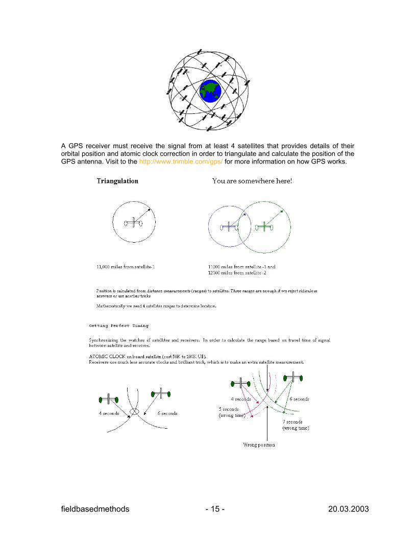
A GPS receiver must receive the signal from at least 4 satellites that provides details of their orbital position and atomic clock correction in order to triangulate and calculate the position of the GPS antenna. Visit to the http://www.trimble.com/gps/ for more information on how GPS works.
fieldbasedmethods - 15 - 20.03.2003
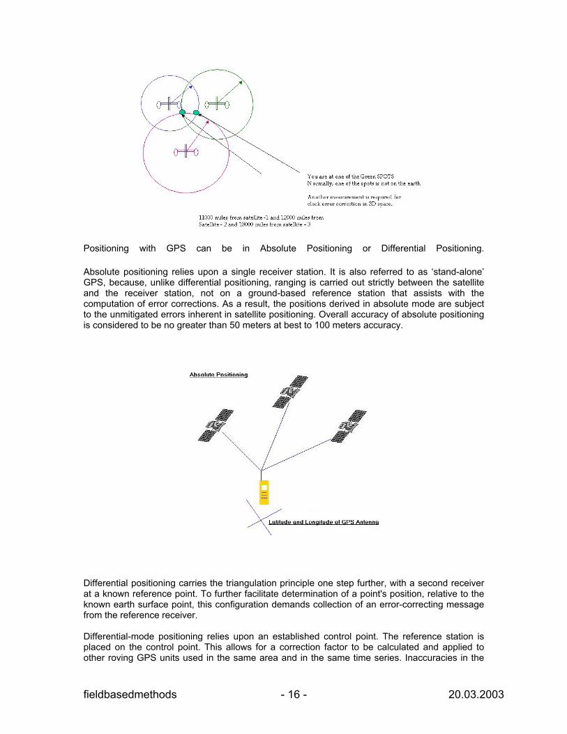
Positioning with GPS can be in Absolute Positioning or Differential Positioning. Absolute positioning relies upon a single receiver station. It is also referred to as ‘stand-alone’ GPS, because, unlike differential positioning, ranging is carried out strictly between the satellite and the receiver station, not on a ground-based reference station that assists with the computation of error corrections. As a result, the positions derived in absolute mode are subject to the unmitigated errors inherent in satellite positioning. Overall accuracy of absolute positioning is considered to be no greater than 50 meters at best to 100 meters accuracy.
Differential positioning carries the triangulation principle one step further, with a second receiver at a known reference point. To further facilitate determination of a point's position, relative to the known earth surface point, this configuration demands collection of an error-correcting message from the reference receiver. Differential-mode positioning relies upon an established control point. The reference station is placed on the control point. This allows for a correction factor to be calculated and applied to other roving GPS units used in the same area and in the same time series. Inaccuracies in the
fieldbasedmethods - 16 - 20.03.2003
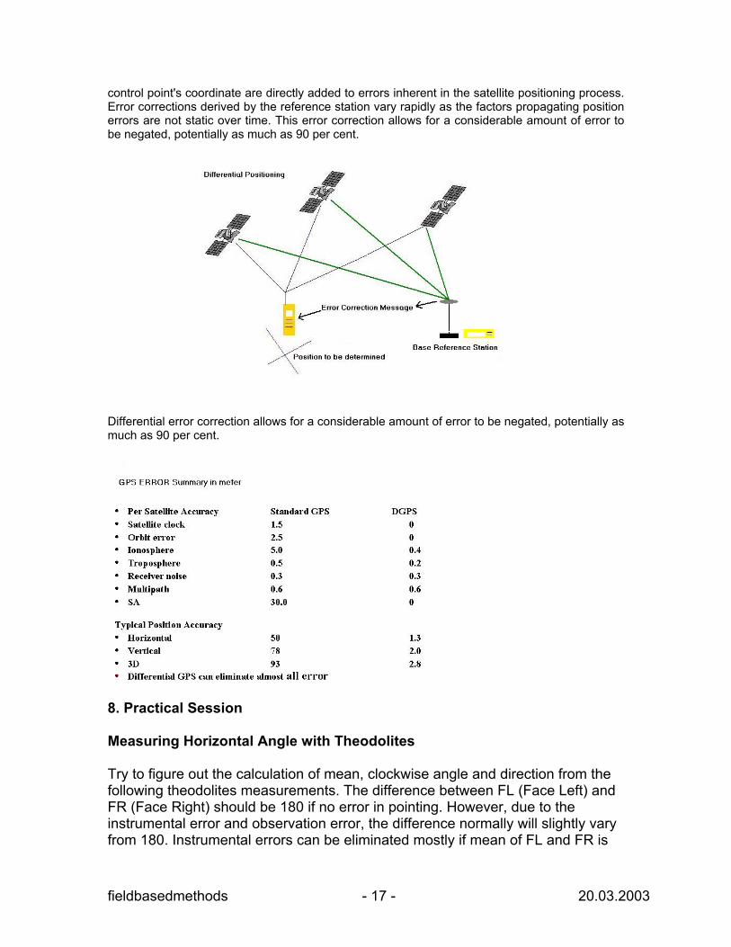
control point's coordinate are directly added to errors inherent in the satellite positioning process. Error corrections derived by the reference station vary rapidly as the factors propagating position errors are not static over time. This error correction allows for a considerable amount of error to be negated, potentially as much as 90 per cent.
Differential error correction allows for a considerable amount of error to be negated, potentially as much as 90 per cent.
8. Practical Session Measuring Horizontal Angle with Theodolites Try to figure out the calculation of mean, clockwise angle and direction from the following theodolites measurements. The difference between FL (Face Left) and FR (Face Right) should be 180 if no error in pointing. However, due to the instrumental error and observation error, the difference normally will slightly vary from 180. Instrumental errors can be eliminated mostly if mean of FL and FR is
fieldbasedmethods - 17 - 20.03.2003
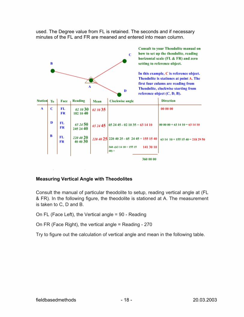
used. The Degree value from FL is retained. The seconds and if necessary minutes of the FL and FR are meaned and entered into mean column.
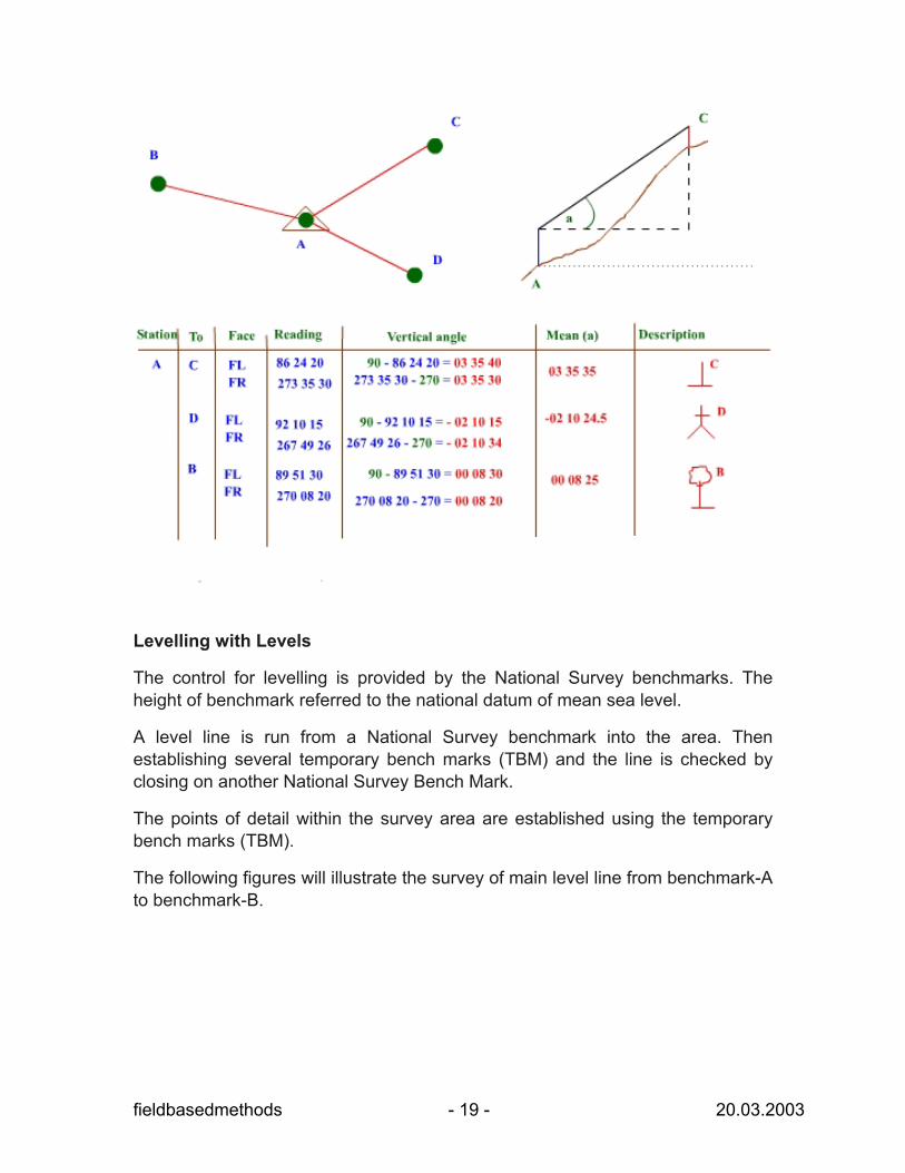
Measuring Vertical Angle with Theodolites Consult the manual of particular theodolite to setup, reading vertical angle at (FL & FR). In the following figure, the theodolite is stationed at A. The measurement is taken to C, D and B.
On FL (Face Left), the Vertical angle = 90 - Reading
On FR (Face Right), the vertical angle = Reading - 270
Try to figure out the calculation of vertical angle and mean in the following table.
fieldbasedmethods - 18 - 20.03.2003
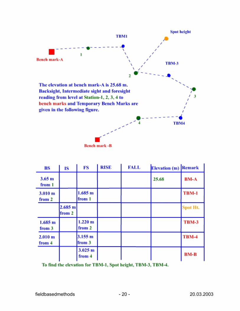
Levelling with Levels
The control for levelling is provided by the National Survey benchmarks. The height of benchmark referred to the national datum of mean sea level.
A level line is run from a National Survey benchmark into the area. Then establishing several temporary bench marks (TBM) and the line is checked by closing on another National Survey Bench Mark.
The points of detail within the survey area are established using the temporary bench marks (TBM).
The following figures will illustrate the survey of main level line from benchmark-A to benchmark-B.
fieldbasedmethods - 19 - 20.03.2003
fieldbasedmethods - 20 - 20.03.2003
fieldbasedmethods - 21 - 20.03.2003
fieldbasedmethods - 22 - 20.03.2003
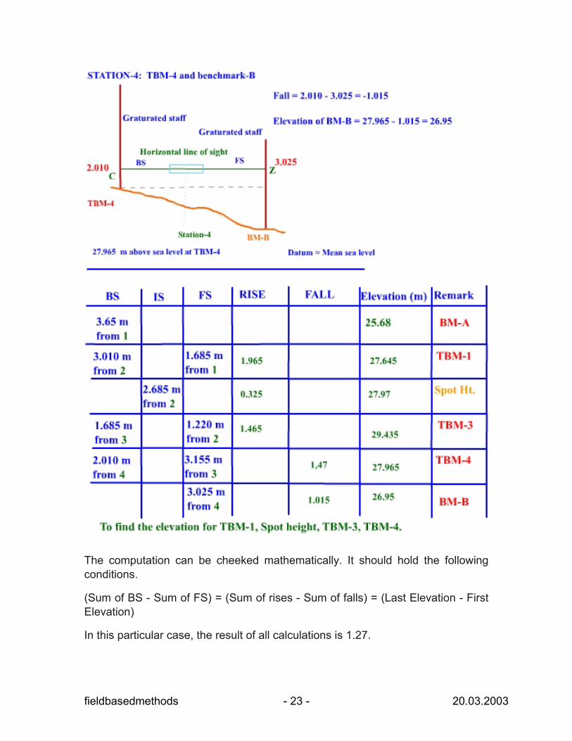
The computation can be cheeked mathematically. It should hold the following conditions.
(Sum of BS - Sum of FS) = (Sum of rises - Sum of falls) = (Last Elevation - First Elevation)
In this particular case, the result of all calculations is 1.27.
fieldbasedmethods - 23 - 20.03.2003
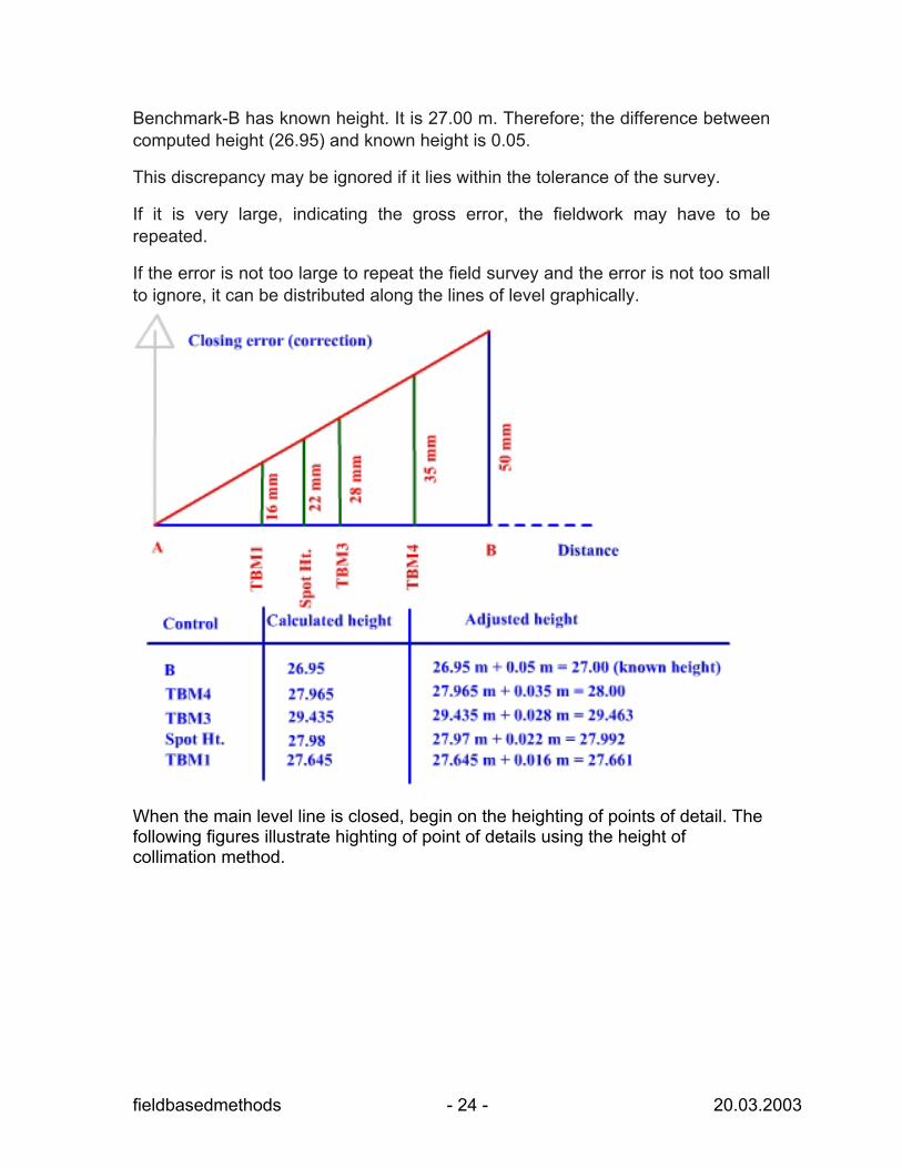
Benchmark-B has known height. It is 27.00 m. Therefore; the difference between computed height (26.95) and known height is 0.05.
This discrepancy may be ignored if it lies within the tolerance of the survey.
If it is very large, indicating the gross error, the fieldwork may have to be repeated.
If the error is not too large to repeat the field survey and the error is not too small to ignore, it can be distributed along the lines of level graphically.
When the main level line is closed, begin on the heighting of points of detail. The following figures illustrate highting of point of details using the height of collimation method.
fieldbasedmethods - 24 - 20.03.2003
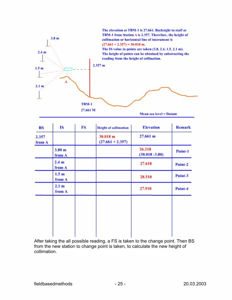
After taking the all possible reading, a FS is taken to the change point. Then BS from the new station to change point is taken, to calculate the new height of collimation.
fieldbasedmethods - 25 - 20.03.2003
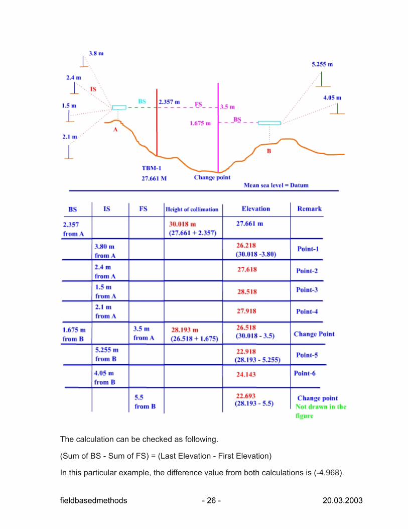
The calculation can be checked as following.
(Sum of BS - Sum of FS) = (Last Elevation - First Elevation)
In this particular example, the difference value from both calculations is (-4.968).
fieldbasedmethods - 26 - 20.03.2003
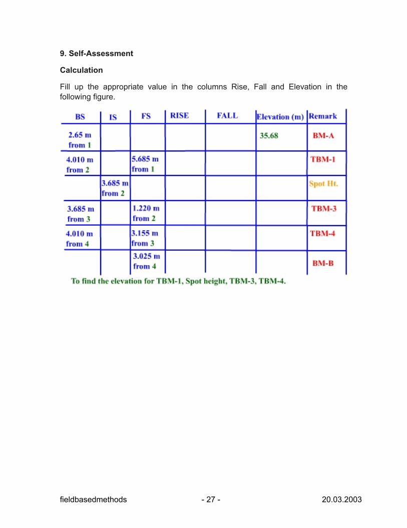
9. Self-Assessment
Calculation
Fill up the appropriate value in the columns Rise, Fall and Elevation in the following figure.
fieldbasedmethods - 27 - 20.03.2003
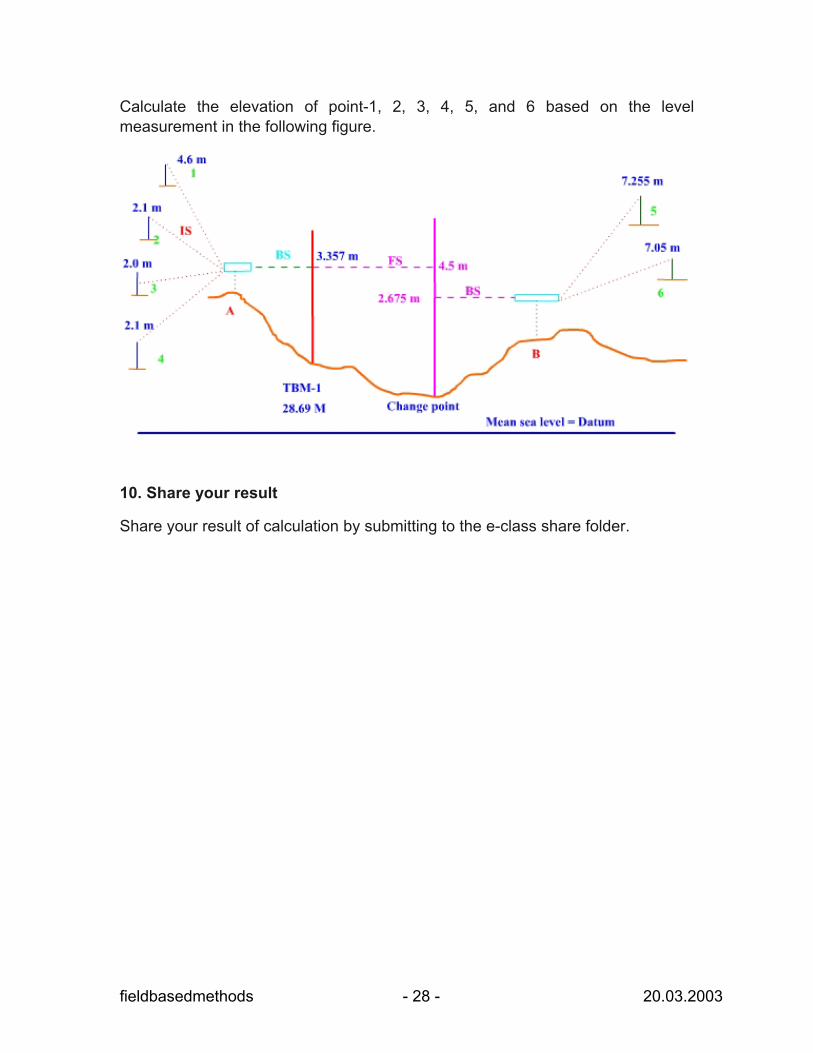
Calculate the elevation of point-1, 2, 3, 4, 5, and 6 based on the level measurement in the following figure.
10. Share your result
Share your result of calculation by submitting to the e-class share folder.
fieldbasedmethods - 28 - 20.03.2003