Embed Size (px)
Citation preview

Ficha técnicaLibro de servicioData sheetService book
2 | 4
FT


FTÍNDICE
1. CARACTERÍSTICAS PRINCIPALES2. CARACTERÍSTICAS TÉCNICAS3. FUNCIONAMIENTO DEL EQUIPO4. INTERFACE. ESTADO EN EL QUESE ENCUENTRA EL SISTEMA5. GARANTÍA6. HOJA DE REGISTRO DE INSTALACIÓNY PUESTA EN SERVICIO DEL EQUIPO7. LIBRO DE SERVICIO. USUARIO
INDEX
1. MAIN SPECIFICATIONS2. TECHNICAL CHARACTERISTICS3. HOW THE EQUIPMENTS WORKS4. INTERFACE. SYSTEM STATUS.5. WARRANTY6. EQUIPMENT INSTALLATION ANDINITIAL OPERATION REGISTRATION SHEET7. SERVICE BOOK. USER.
469
910
1112
1416181920
2123

Espa
ñol
Espa
ñol
4
1. CARACTERÍSTICAS PRINCIPALES PUMP
PRESSURE PUMPMayor producción y rendimiento
SOLENOID VALVEControl inmediato.Malla de seguridad incorporada
PRESSURE CONTROLProtección de caídas depresión en la red
DOUBLE FLOWMayor caudal de agua dispensada
REMINERALIZERPostfiltro ajustador de pH
CLICKConexiones rápidas y de máxima seguridad
ELECTRONIC ADAPTERMayor seguridad y eficiencia
DIRECT ACCESSFacilidad de acceso y mantenimiento
CS FILTERSFiltros exclusivos. Máximaseguridad e higiene
INSERTMáxima seguridad enlas conexiones de tubos
Q CARBONCarbón según norma UNE EN 12915-1
RELIABLE CONNECTIONSConectores rápidos.Máxima seguridad

Espa
ñol
Espa
ñol
5
PUMP
AQUASTOPSistema automático dedetección de fugas
INTERFACEEquipo parametrizable y adaptablea las necesidades del usuariomediante interface a ordenador
FILTER CONTROLAviso automático de mantenimiento
QUALITY CONTROLControl de la conductividaddel agua producida
SOUND WARNINGSAvisos sonoros
SWITCHInterruptor eléctrico paramantenimiento seguro
FLUSHING READYPreparada para montaje rápidode sistema de limpieza de membrana
EL EQUIPO POSEE LA CARACTERÍSTICA INDICADA CON EL SÍMBOLO

Espa
ñol
Espa
ñol
6
2. CARACTERÍSTICAS TÉCNICAS
AplicaciónTratamiento del agua •Ósmosis inversa
Uso •Mejora de las características del agua potable (que cumpla con los requisito de la Directiva Europea sobre Agua de consumo humano 98/83 o sus trasposicines nacionales en los distintos estados miembros de la Comunidad Europea).
Modificaciones por reducción o aporte •Eltratamientodeaguamedianteósmosisinversaescapazdereducirconcentra ciones de sales y otras substancias en elevados porcentajes. •Reducciónmínima*dedeterminadoscompuestosyparámetros: Sodio – 90 % Calcio – 90% Sulfato – 90% Cloruro – 90% DurezaTotal–90% Conductividad – 90%
(*)Enfuncióndelascaracterísticasdelaguaatratar.
Datos técnicos PUMPTipo de control Presostatodemáximapresión. Electroválvuladepasodecontrol de entrada.Sistema de seguridad Presostatodemínimapresión. Sensordefugaselectrónico. Control de calidad del agua. Aviso de mantenimiento. Interruptor posteriorDimensiones (mm) 435x250x420 (A x B x C) Peso (kg) 13Depósito (dimensiones) IntegradoVolumen total depósito 5,5 lConexión entrada 1/4”Conexión desagüe 1/4”Conexión grifo 3/8”Adaptador pared 3/8”M-F*****Collarín desagüe Abrazaderaparatubo de desagüe de 40 mmPrefiltros 1xCSSedimentos 2xCSGAC
Límites de funcionamiento PUMPPresión (máx./mín.) 2,5bar(250kPa) 1bar(100kPa)TDS (máx.) 2000ppm
Temperatura (máx./mín.) 40ºC–2ºC
Dureza (máx.) 15ºHF**
ENTRADA DESAGÜE GRIFO
A
BC
OUT/SALIDAIN/ENTRADA
IN:ESPIGA3/8”OUT:ESPIGA3/8”

Espa
ñol
Espa
ñol
7
Datos técnicos PUMPMembrana 1812x50GPDGREENFILTER
Postfiltro 1xFP-AREMINERALIZADOR
Alimentación eléctrica 24Vdc1,25AAdaptador eléctrico 100-240Vac50/60Hz:24VdcTipo de grifo Klein 1 víaProducción 0,25lpm. Sincontrapresión. Aguaatratar15ºHF. 200ppm,20ºC,5bar****Sistema electrónico de PJK-260-A+PJK031control y gestión
Esquema hidráulico PUMP
IN/ENTRADA
OUT/R OUT/RO
IN:RH1/8”OUT:RORH1/8”OUT:RRH1/8”
OUT/SALIDA
IN/ENTRADA
IN:ESPIGA3/8”OUT:RM1/4”

Espa
ñol
Espa
ñol
8
Datos técnicos
Esquema eléctrico PUMP
Esquema de conexionado hidráulico* Para salinidades superiores a 2000 ppm, consulte con su distri-buidor. Atención: una elevada salinidad y/o baja presión de entrada puede provocar que el equipo SO se encuentre fuera de sus límites de funcionamiento, imposibilitando o limitando sustancialmente el proceso de ósmosis inversa.** Durezas superiores podrán reducir la vida y funcionamiento de de-terminados componentes.*** Acumulación máxima en función de la presión de entrada.**** Los caudales pueden variar un 20% en función de la temperatu-ra, presión y composición concreta del agua a tratar.***** Podrá variar en función del modelo.
100/110/220/240 Vac50 / 60 Hz 24 Vdc
LPS HPS
Si
P
R - PJK 260
Sf
PJK260
L
Q
FABRICADO POR:PURICOMINDUSTRIALWATERCORPORATION(Taiwan)
DISTRIBUIDO POR: IONFILTER.PURICOMEUROPE.PURICOMAMÉRICAPol.Ind.L’AmetllaPark.C.Aiguafreda,8.08480L’AmetlladelVallès.Barcelona(España)T.902305310F.+34936934329
•Losequiposconbomba(PUMP)controlanelllenadodeldepósitomedianteunpresostato(HPS)
•Alsolicitaraguapormediodelgrifodelequipo,elaguaacumulada en el tanque pasa a través de un postfiltro (R)cuyafinalidadeslaeliminacióndeposiblesoloresysabores,asícomoajustarelpH(enfuncióndelmodelo)que pudiese retener el agua antes de ser dispensada.
•Enfuncióndelmodelo,losequiposincorporandistin-tos sistemas funcionales y/o de seguridad, gestionados porunmóduloelectrónicodeúltimageneración:
• Sistema electrónico de detección de fugas (L).Cuandoelsistemadetectaestasituación,bloqueaelequipoemitiendounaseñalacústicayluminosainformando al respecto. El equipo permanecerábloqueadohastaquelasondadedetecciónseen-cuentre seca.
•Sondadeestimacióndelaconductividaddelaguaproducidaparaevaluacióndelestadoenelqueseencuentra la membrana y componentes (Q). Al pul-sarelbotónfrontal,elsistemarealizaráunamedi-cióndelaconductividaddelaguaproducida.
3. FUNCIONAMIENTO DEL EQUIPO
•Elaguaderedatratarentraenelequipoatravesandolaetapadeprefiltraciónqueincorporafiltrosdeturbie-dad(S)ydecarbónGAC(G).Enestaetapadefiltración,quedanretenidaslaspartículasensuspensión,elcloro,susderivadosyotrassustanciasorgánicas.
•Elpasodelaguahaciaelinteriordelequipoescontro-ladomedianteunaelectroválvuladecorte(Si)oválvulamecánicade4vías(enfuncióndelmodelo).
• Los equipos con bomba (PUMP) incorporan un pre-sostatodemínimapresiónparaprotegerlabombaantecaídasdepresiónenlared(LPS).
•Elagua,trassertratadaenlaetapadefiltración,esimpulsadahacialamembranadeósmosisinversa(M).Enfuncióndelmodelo,elequipopodráincorporarunabomba (P) para aumentar la presión. La presión delagua sobre la membrana hace posible el proceso de ósmosisinversa.
•El aguaosmotizada se almacenaenundepósito deacumulaciónparasuposteriorconsumo.Elaguadere-chazooconexcesodesalesyotrassustanciasdisueltassedirigehaciaeldesagüeparasueliminación.
ENTRADA DESAGÜE GRIFO
GRIFO DESAGÜE ENTRADA

Espa
ñol
Espa
ñol
9
•Avisoautomáticodecambiodefiltros,conobjetode informaralusuariodequesedeberealizarelmantenimiento adecuado para garantizar la cali-dad del agua dispensada.
INDICACIÓN ACÚSTICA
4. INTERFACE. ESTADO EN EL QUE SE ENCUENTRA EL SISTEMA
CONTROLADOR PJK-260-A + PJK -031
INDICACIÓN VISUAL
LED AZUL“Power”
LED VERDE“Water quality detector”
LED AZUL“Power”
LED VERDE“Water quality detector”
LED VERDE“Water quality detector”
LED ROJO“Leaking sensor/filters”
LED ROJO“Leaking sensor/filters”
LED ROJO“Leaking sensor/filters”
Equipo alimentado eléctricamente.-
-
-
-
x1
x1
x2
Indica calidad de agua producida óptima tras pulsar el botón PUSH del panel frontal.
Indica calidad reducida de agua producida óptima tras pulsar el botón PUSH del panel frontal.
Sistema de funcionamiento correcto. Si no se ilumina tras pulsar el botón PUSH del panel frontal, existe una alarma de mayor prioridad activada e indicándose.El mantenimiento necesario / cambio de filtros debe ser realizado inminentemente. Equipo bloqueado. *
Fuga de agua detectada. Equipo Bloqueado. *
El mantenimiento necesario / cambio de filtros deberá ser realizado en breve. *
Incidencia o funcionamiento incorrecto del sistema eléctrico/electrónico.
PULSADORESTADOLED
SIGNIFICADO
- Led no iluminado - Led iluminado fijo Led iluminado parpadeo simple
Led iluminado parpadeo doble Señales acústicas Señal acústica periódica
x1
-
-
-
-
-
-
* Póngase en contacto con su Servicio Técnico.** Cuando detecte que el equipo se encuentra en al-guno de los estados descritos, póngase en contacto con el servicio de mantenimiento para concertar la cita y así realizar el mantenimiento que el equipo requiere.Vea el correspondiente apartado en el ManualTécnico.Póngase en contacto con su Servicio Técnico si el equipo no detuviera la producción (llegando a llenar
el depósito) tras varias horas de funcionamiento conti-nuo, sin haberse producido extracción de agua.Póngase en contacto con su Servicio Técnico si de forma reiterada el equipo se encuentra bloqueado por falta de presión de agua de red a la entrada del mismo y habiendo presión en el resto de la vivienda.Póngase en contacto con su Servicio Técnico si, despues de abrir el grifo, el equipo se encontrase en
reposo, sin dispensar agua a través del grifo ni mostrar ningún tipo de alarma.Los avisos acústicos no son continuados, durando unos segundos (10”). Mientras la alarma continúe indicándose por medio de los LEDs del panel, el aviso acústico se emitirá periódicamente cada 7 horas.
x2

Espa
ñol
Espa
ñol
10
5. GARANTÍA
GARANTÍA DEL EQUIPO DIRIGIDA AL USUARIO FINAL:
EMPRESA Y/O INSTALADOR AUTORIZADO: (fecha y firma)
TELÉFONO DE ASISTENCIA TÉCNICA:
IDENTIFICACIÓN DEL EQUIPO:
S/O
P/N
S/N
El distribuidor garantiza los equipos durante el período de dos años ante cualquier falta de conformidad que se detecte en los mismos tal y como dispone el RD 1/2007 de 16 de noviembre (Texto refundido de la Ley General de Defensa de los Consumidores y usuarios) La garantía comprende la reparación y sustitución de las piezas defectuosas por el personal autorizado por el Distribuidor o el Servicio de Asistencia Técnica Oficial (SAT), en el lugar de la instalación o en sus talleres. Se incluye en la garantía la mano de obra y los gastos de envío que se puedan generar. IF/PEU/PAM* queda exonerado de prestar garantía en los casos de piezas sometidas al desgaste natural, falta de mantenimiento, golpes u otras faltas de conformidad que sean consecuencia de un uso indebido del equipo o inadecuado según las condiciones y límites de funcionamiento indicadas por el fabricante del mismo. Asimismo la garantía pierde eficacia en supuestos de mala manipulación y uso de los equipos, o en aquellos casos en los que han sido modificados o reparados por personal ajeno a la empresa distribuidora o SAT oficial. Las piezas sustituidas en garantía quedarán en propiedad de IF/PEU/PAM*IF/PEU/PAM* responde por la falta de conformidad del equipo cuando ésta se refiera al origen, identidad o idoneidad de los productos, de acuerdo con su naturaleza y finalidad. Teniendo en cuenta las características de los equipos es imprescindible para que la garantía cubra la falta de conformidad, la cumplimentación de las condiciones técnicas de instalación y funcionamiento de la presente hoja de garantía; así como la factura o ticket de compra. La falta de cumplimentación de dichas condiciones puede comportar la ausencia de garantía, teniendo en cuenta la relevancia del destino del equipo y las condiciones y límites de funcionamiento en las que debe operar el mismo.El distribuidor garantiza que el equipo instalado es adecuado para la mejora de la calidad del agua a tratar en particular, según características del equipo y normativa vigente. El instalador y/o distribuidor garantiza la correcta instalación y puesta en marcha del equipo, según lo indicado por el fabricante y normativa vigente y además responderá por la falta de conformidad derivada de una incorrecta aplicación, instalación o puesta en marcha del equipo.Para cualquier reclamación en garantía es preciso presentar la factura de compra. El plazo de 2 años se computa desde la compra del equipo al distribuidor.Si durante el período de garantía su equipo presenta algún problema contacte con su distribuidor.En caso de instalación del equipo, con agua a tratar de durezasuperior a 25ºF, IF/PEU/PAM* no se hará responsable delas averías, mal funcionamiento y consecuencias de losmismos, provocados por las características del agua.
* IF/PEU/PAM = IONFILTER/PURICOM EUROPE/ PURICOM AMÉRICA
El equipo queda instalado y en funciona-miento de forma satisfactoria para el cliente y para que conste:*Tratamiento previo al equipo RO:
*Dureza de entrada equipo RO [ºF]:
*TDS de entrada equipo RO [ppm]:
*Presión de entrada equipo RO [bar]:
*TDS Agua producida (Grifo) [ppm]:
*Resultado de la hoja de instalación y puesta en servicio CORRECTO.
OTROS: El propietario del equipo ha sido informado adecuada y claramente del uso, manipulación y mantenimiento que el equipo requiere para garantizar su correcto funcionamiento y la calidad del agua producida. A tal efecto se le ofrece un contrato de mantenimiento. *Ref. Contrato de mantenimiento
ACEPTA el contrato de mantenimiento. NO ACEPTA el contrato de mantenimiento.
En caso de necesitar información, comunicación de avería o mal funcionamiento, solicitud de mantenimiento o intervención de un técnico, lea previamente los apartados de funcionamiento, detección y resolución de problemas de este manual y póngase en contacto con el distribuidor o empresa que le vendió su equipo.

Espa
ñol
Espa
ñol
11
6. HOJA DE REGISTRO DE INSTALACIÓN Y PUESTA EN SERVICIO DEL EQUIPO. TÉCNICO
HOJA A CUMPLIMENTAR POR EL TÉCNICO INSTALADOR. HOJA PARA EL TÉCNICO INSTALADOR.
HOJA DEL REGISTRO DE INSTALACIÓN Y PUESTA EN SERVICIO DEL EQUIPO
NOTAS PARA TÉCNICO/INSTALADOR: Lea atentamente el presente Manual. Ante cualquier duda, póngase en contacto con el servicio de atención técnica (S.A.T.) de su distribuidor.
Los datos marcados con (*) debe rellenarlos el técnico instalador y transcribirlos él mismo a la HOJA DE GARANTÍA.Esta hoja deberá ser conservada por el instalador/distribuidor y podrá ser requerida por IF/PEU/PAM*, con objeto de mejorar el servicio postventa y de atención al cliente.El técnico que realice la instalación y puesta en servicio del equipo deberá tener la capacitación técnica adecuada.
S/O
P/N
S/N
COMENTARIOS
*Resultado de la instalación y puesta en servicio:
CORRECTO (equipo instalado y funcionando correcta-
mente. Agua producida adecuada a la aplicación.)
OTROS:
IDENTIFICACIÓN DEL TÉCNICO/INSTALADOR AUTORIZADO:
Empresa y/o instalador, fecha y firma:
CONFORMIDAD DEL PROPIETARIO DEL EQUIPO:
He sido informado claramente del uso, manipulación y
mantenimiento que requiere el equipo instalado, habién-
doseme ofrecido un contrato de mantenimiento e infor-
mado de cómo contactar con un Servicio de Atención al
Cliente, en caso de solicitar información, comunicación de
avería o mal funcinamiento, solicitud de mantenimiento o
intervención de un técnico.
Comentarios
*Ref. Contrato de mantenimiento
ACEPTA el contrato de mantenimiento.
NO ACEPTA el contrato de mantenimiento.
Modelo / Ref.:
Propietario Sr./Sra.:
Calle:
Teléfono/s:
Población:
Provincia: C.P:
Fecha y firma:
DATOS SOBRE LA APLICACIÓN DEL EQUIPO:
Procedencia del agua a tratar:
Red de abastecimiento público.
Otras:
*Tratamiento previo al equipo RO:
*Dureza entrada equipo RO [ºF]:
*TDS entrada equipo RO [ppm]:
*Presión de entrada equipo RO [bar]:
Concentración Cloro entrada equipo RO [ppm]:
CONTROL DE LOS PASOS DE LA INSTALACIÓN:
Lavado de prefiltros de carbón.
Lavado de postfiltro de carbón.
Montaje membrana.
Higienización según protocolo descrito.
Comprobación restrictor caudal.
Tarado del presostato de máxima.
Revisión y racorería.
Estanqueidad sistema presurizado.
*TDS agua producida (grifo encimera) [ppm]:
Informar claramente del uso, manipulación y manten-imiento que el equipo requiere para garantizar un correcto funcionamiento del mismo y la calidad de agua producida. Dada la importancia que un correcto mantenimiento del equipo tiene para garantizar la calidad del agua producida, al propietario se le deberá ofrecer un contrato de manten-imiento realizado por técnicos capacitados para ello.

Espa
ñol
Espa
ñol
12
MANTENIMIENTO COMPLETO
REPARACIÓN
HIGIENIZACIÓN
OTROS
/ /
/ /
/ /
/ /
MANTENIMIENTO COMPLETO
REPARACIÓN
HIGIENIZACIÓN
OTROS
/ /
/ /
/ /
/ /
MANTENIMIENTO COMPLETO
REPARACIÓN
HIGIENIZACIÓN
OTROS
/ /
/ /
/ /
/ /
MANTENIMIENTO COMPLETO
REPARACIÓN
HIGIENIZACIÓN
OTROS
/ /
/ /
/ /
/ /
MANTENIMIENTO COMPLETO
REPARACIÓN
HIGIENIZACIÓN
OTROS
/ /
/ /
/ /
/ /
TIPO DE SERVICIOFECHA NOMBRE, FIRMA Y SELLODEL TÉCNICO AUTORIZADO
MANTENIMIENTO COMPLETO
REPARACIÓN
HIGIENIZACIÓN
OTROS
/ /
PUESTA EN MARCHA/ /
/ /
/ /
/ /
TÉCNICO
ORDINARIA
EXTRAORDINARIA
GARANTÍA
SELLO
TÉCNICO ORDINARIA
EXTRAORDINARIA
GARANTÍA
SELLO
TÉCNICO ORDINARIA
EXTRAORDINARIA
GARANTÍA
SELLO
TÉCNICO ORDINARIA
EXTRAORDINARIA
GARANTÍA
SELLO
TÉCNICO ORDINARIA
EXTRAORDINARIA
GARANTÍA
SELLO
TÉCNICO ORDINARIA
EXTRAORDINARIA
GARANTÍA
SELLO
6. HOJA DE REGISTRO DE INSTALACIÓN Y PUESTA EN SERVICIO DEL EQUIPO. TÉCNICO

Espa
ñol
Espa
ñol
13
MANTENIMIENTO COMPLETO
REPARACIÓN
HIGIENIZACIÓN
OTROS
/ /
/ /
/ /
/ /
MANTENIMIENTO COMPLETO
REPARACIÓN
HIGIENIZACIÓN
OTROS
/ /
/ /
/ /
/ /
MANTENIMIENTO COMPLETO
REPARACIÓN
HIGIENIZACIÓN
OTROS
/ /
/ /
/ /
/ /
MANTENIMIENTO COMPLETO
REPARACIÓN
HIGIENIZACIÓN
OTROS
/ /
/ /
/ /
/ /
MANTENIMIENTO COMPLETO
REPARACIÓN
HIGIENIZACIÓN
OTROS
/ /
/ /
/ /
/ /
TIPO DE SERVICIOFECHA NOMBRE, FIRMA Y SELLODEL TÉCNICO AUTORIZADO
MANTENIMIENTO COMPLETO
REPARACIÓN
HIGIENIZACIÓN
OTROS
/ /
PUESTA EN MARCHA/ /
/ /
/ /
/ /
TÉCNICO
ORDINARIA
EXTRAORDINARIA
GARANTÍA
SELLO
TÉCNICO ORDINARIA
EXTRAORDINARIA
GARANTÍA
SELLO
TÉCNICO ORDINARIA
EXTRAORDINARIA
GARANTÍA
SELLO
TÉCNICO ORDINARIA
EXTRAORDINARIA
GARANTÍA
SELLO
TÉCNICO ORDINARIA
EXTRAORDINARIA
GARANTÍA
SELLO
TÉCNICO ORDINARIA
EXTRAORDINARIA
GARANTÍA
SELLO
7. LIBRO DE SERVICIO. USUARIO
Atención: los intervalos recomendados de mantenimiento se encuentran descritos en el correspondiente apartadodel Manual Técnico.

Engl
ish
14
1. MAIN SPECIFICATIONS PUMP
PRESSURE PUMPHigher performance and production
SOLENOID VALVEImmediate control. Built-in safety mesh
PRESSURE CONTROLProtection against pressure drops in the supply network
DOUBLE FLOWHigher flow of produced water
REMINERALIZERpH-regulating post-filter
CLICKQuick connectors and maximum safety
ELECTRONIC ADAPTERHigher safety and efficiency
DIRECT ACCESSEasy access and maintenance
CS FILTERSExclusive filters. Maximum safety and hygiene
INSERTMaximum safety in all threaded connections
Q CARBONUNE EN 12915-1 compliant carbon
QUICK CONNECTORQuick connectors.Maximum security.

Engl
ish
15
PUMP
AQUASTOPAutomatic leakage sensor
INTERFACEThe equipment can be configured and adapted to the user's needs through a computer interface
FILTER CONTROLAutomatic maintenance warning
QUALITY CONTROLControl of conductivity of water produced
SOUND WARNINGSAcoustic warnings
FLUSHING READYAutoflushing solenoid valve preassembly kit
SWITCHElectrical switch for safety maintenance
THE EQUIPMENT FEATURES THE OPTION MARKED WITH

Engl
ish
16
2. TECHNICAL CHARACTERISTICS
Application Water treatment •Reverseosmosis
Use •Improvesthedrinkingwater’scharacteristics(meetingallEuropeanDirectiveon WaterforHumanConsumption98/83requirementsanditsnationaltranspositions in the various EU member states).
Modifications due to reduction or contribution •Watertreatmentviareverseosmosisisabletogreatlyreducesaltandother concentrations. •Minimumreduction*ofspecificcompoundsandparameters: Sodium – 90 % Calcium – 90% Sulphates – 90% Chloride – 90% TotalHardness–90% Conductivity – 90% (*)Dependingonthecharacteristicsofthewatertobetreated(inthemembraneoutlet). Thesevaluesmayvaryinfunctionofthetypeofpost-filterusedbytheequipmentand/orsetting ofthemixingvalve(whereapplicable).
Technical Information PUMPControl type High pressure switch. Inlet solenoid valve
Safety lock Low pressure switch. Electronicleakingsensor. Waterqualitycontrol. Maintenancewarning. Switch
Dimensions (mm) 435x250x420 (A x B x C) Weight (kg) 13Tank (dimensions) Built-in Total tank volume 5.5 lEntry connection 1/4”Drain connection 1/4”Tap connection 3/8”Wall adapter 3/8”M-F*****Drain collar 40mm drain tube clampPre-filters 1xCSSediments 2xCSGAC
Working limits PUMPPressure (max./min.) 2.5bar(250kPa) 1bar(100kPa)TDS (max.) 2000ppm
Temperature (max./min.) 40ºC–2ºC
Hardness (max.) 15ºHF**
ENTRADA DESAGÜE GRIFO
IN:STEM3/8”OUT:STEM3/8”
IN/INLETOUT/OUTLET

Engl
ish
17
Technical Information PUMPMembrane 1812x50GPDGREENFILTER
Post-filter 1FPAxREMINERALIZER
Power supply 24Vdc1,25AElectrical adaptor 100-240Vac50/60Hz:24VdcTap type Klein1wayProduction 0,25lpm. Withoutcounterpressure. Watertobetreated15ºHF. 200ppm,20ºC,2bar****Control and management PJK-260-A+PJK-031electronic system Hydraulic diagram PUMP
IN/INLET
OUT/R OUT/RO
IN:RH1/8”OUT:RORH1/8”OUT:RRH1/8”
OUT/OUTLET
IN/INLET
IN:STEM3/8”OUT:RM1/4”
Engl
ish
18
Technical Information
Electrical diagram PUMP
Hydraulic connections diagram * For salinity levels above 2000 ppm, please check with your distri-butor. Warning: a high salinity rate and/or low entry pressure may cause the machine to operate outside of its working limits thus substantially limiting or preventing the reverse osmosis process. ** Higher levels of hardness can reduce the service life and co-rrect function of certain components. ***Maximum accumulation may vary depending on the model. **** Flows can vary by up to 20% in function of the temperature, pressure and specific composition of the water to be treated. ***** Possible variations depending on the model chosen.
MANUFACTURED BY: PURICOMINDUSTRIALWATERCORPORATION(Taiwan)
DISTRIBUTED BY: IONFILTER.PURICOMEUROPE.PURICOMAMÉRICAPol.Ind.L’AmetllaPark.C.Aiguafreda,8.08480L’AmetlladelVallès.Barcelona(Spain)T.902305310F.+34936934329
thetankflowsthroughapost-filteringstage(R)whoseaim is the elimination of possible odours and taste, as wellaspHleveladjustment(dependingonthemodel),whichthewatermayretainbeforebeingdispensed.
•Dependingonthemodel,theappliancesmayhavedi-fferent functional and/or safety systems, managed by a state-of-the-artelectronicmodule:
•Electronicsystemfor leakagedetection(L).Whenthesystemdetectsthiscondition,itblocksthesystemand emits an acoustic signal and a light signal to in-formaboutthesituation.Theunitwillremainblockeduntiltheleakagesensorisdry.
• Probe used to estimate the conductivity of waterproduced, thus assessing the state of the membrane and the components (Q). Press the front button to me-asuretheconductivityofwaterproduced.
•Automaticfilterchangewarning,inordertoinformthe user that proper maintenance must be carried out toguaranteethequalityofwaterproduced.
3. HOW THE EQUIPMENT WORKS
•Themainswatertobetreatedisfedthroughtheequi-pment after passing through the pre-filtering stage that incorporates a turbidity (S) and carbon filter (C). During this filtering stage, chlorine, its derivatives and other organic substance particles are retained.
•Waterflowtowardstheapplianceiscontrolledeitherbya4waysshutoffvalve(So)orbyasolenoidvalve(Si)(depending on the model).
•Theunitwithapump(PUMP)haveabuilt-inlowpres-sureswitchtoprotectthepumpagainstpressuredropsfromthenetwork(LPS).
• After the filtering stage, water flows towards thereverse osmosis membrane (M). Depending on each model, the appliance may incorporate a pump (P) to in-creasepressure. It is theeffectof thewaterpressureuponthemembrane,whichmakesthereverseosmosispossible.
•Thetreatedwaterisstoredinthetank(T)foritssub-sequentuse.Waterthatisrejectedorhasexcessivesaltorotherdissolvedsubstancesflowstowards thedrainoutlet(G)tobedisposedof.
•Theequipmentwithapump(PUMP)controlthefillingofthetankviaapressureswitch(HPS).
•Whenthesystem’stapisturnedon,thewaterstoredin
INLET DRAIN FAUCET
FAUCET DRAIN INLET

Engl
ish
19
4. INTERFACE. SYSTEM STATUS.
ACOUSTICINDICATION
CONTROLLER PJK-260-A + PJK -031
VISUAL INDICATION
BLUE LED“Power”
GREEN LED“Water quality detector”
BLUE LED“Power”
GREEN LED“Water quality detector”
GREEN LED“Water quality detector”
RED LED“Leaking sensor/filters”
RED LED“Leaking sensor/filters”
RED LED“Leaking sensor/filters”
Electrically powered system.-
-
-
-
x1
x1
x2
When the PUSH-button on the front panel is pressed, it indicates that the quality of water produced is excellent.
When the PUSH-button on the front panel is pressed, it indicates that the quality of water produced is poor.
The system is working properly. If it doesn’t light up after pressing the PUSH-button on the front panel, it means that another alarm of a higher priority has lit up.Carry out the maintenance/change the filters immediately. System blocked. *
A water leak has been detected. System bloc-ked. *
Carry out the maintenance/change the filters soon. *
The electric/electronic system is not wor-king properly/has failed.
PUSHBUTTON
LED STATE
MEANING
- Led is off - Led is permanently on LED is on: single flashing
Led is on: double flashing S Acoustic signals Regular acoustic signal
x1
-
-
-
-
-
-
* Contact your service.** When you detect any of the states described abo-ve, contact with the maintenance service to arrange appointment. See the relevant section in the Manual Technical.Contact your service if the unit does not stops pro-ducing water (after completely filling the tank) after several hours, without any water extraction.
Contact your service if the unit blocks repeatedly due to low water pressure and having pressure water on the rest of the house.Contact your service if , after opening the faucet, the unit would find at rest, without dispensing water using the tap or showing any alarm.The beeps are not continuous; they last a few seconds (10 “). While maintenance state is maintained it will be
indicated by LEDs on the panel and acoustic notifica-tion periodically every 7 hours.
x2
Engl
ish
20
5. WARRANTY
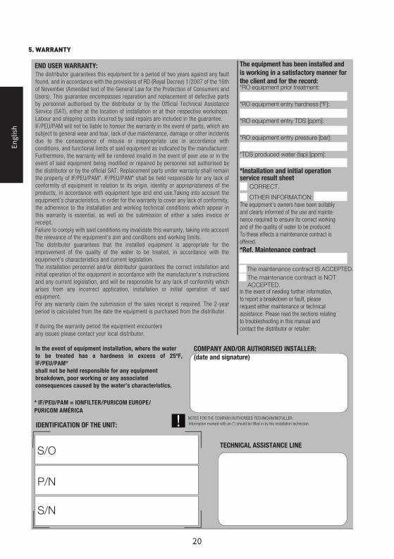
END USER WARRANTY:
COMPANY AND/OR AUTHORISED INSTALLER: (date and signature)
TECHNICAL ASSISTANCE LINES/O
P/N
S/N
* IF/PEU/PAM = IONFILTER/PURICOM EUROPE/ PURICOM AMÉRICA
The equipment has been installed and is working in a satisfactory manner for the client and for the record:
*RO equipment prior treatment:
*RO equipment entry hardness [ºF]:
*RO equipment entry TDS [ppm]:
*RO equipment entry pressure [bar]:
*TDS produced water (tap) [ppm]:
*Installation and initial operation service result sheet CORRECT.
OTHER INFORMATION: The equipment’s owners have been suitably and clearly informed of the use and mainte-nance required to ensure its correct workingand of the quality of water to be produced. To these effects a maintenance contract is offered.
*Ref. Maintenance contract
The maintenance contract IS ACCEPTED. The maintenance contract is NOT
ACCEPTED. In the event of needing further information, to report a breakdown or fault, please request either maintenance or technical assistance. Please read the sections relating to troubleshooting in this manual and contact the distributor or retailer.
NOTES FOR THE COMPANY/AUTHORISED TECHNICIAN/INSTALLER:Information marked with an (*) should be filled in by the installation technician.IDENTIFICATION OF THE UNIT:
The distributor guarantees this equipment for a period of two years against any fault found, and in accordance with the provisions of RD (Royal Decree) 1/2007 of the 16th of November (Amended text of the General Law for the Protection of Consumers and Users). This guarantee encompasses reparation and replacement of defective parts by personnel authorised by the distributor or by the Official Technical Assistance Service (SAT), either at the location of installation or at their respective workshops. Labour and shipping costs incurred by said repairs are included in the guarantee. IF/PEU/PAM will not be liable to honour the warranty in the event of parts, which are subject to general wear and tear, lack of due maintenance, damage or other incidents due to the consequence of misuse or inappropriate use in accordance with conditions, and functional limits of said equipment as indicated by the manufacturer. Furthermore, the warranty will be rendered invalid in the event of poor use or in the event of said equipment being modified or repaired by personnel not authorised by the distributor or by the official SAT. Replacement parts under warranty shall remain the property of IF/PEU/PAM*. IF/PEU/PAM* shall be held responsible for any lack of conformity of equipment in relation to its origin, identity or appropriateness of the products, in accordance with equipment type and end use.Taking into account the equipment’s characteristics, in order for the warranty to cover any lack of conformity, the adherence to the installation and working technical conditions which appear in this warranty is essential, as well as the submission of either a sales invoice or receipt. Failure to comply with said conditions my invalidate this warranty, taking into account the relevance of the equipment’s aim and conditions and working limits. The distributor guarantees that the installed equipment is appropriate for the improvement of the quality of the water to be treated, in accordance with the equipment’s characteristics and current legislation. The installation personnel and/or distributor guarantees the correct installation and initial operation of the equipment in accordance with the manufacturer’s instructions and any current legislation, and will be responsible for any lack of conformity which arises from any incorrect application, installation or initial operation of said equipment. For any warranty claim the submission of the sales receipt is required. The 2-year period is calculated from the date the equipment is purchased from the distributor.
If during the warranty period the equipment encounters any issues please contact your local distributor.
In the event of equipment installation, where the water to be treated has a hardness in excess of 25ºF, IF/PEU/PAM*shall not be held responsible for any equipment breakdown, poor working or any associated consequences caused by the water’s characteristics.

Engl
ish
21
6. EQUIPMENT INSTALLATION AND INITIAL OPERATION REGISTRATION SHEET. TECHNICIAN

Engl
ish
22
MANTENIMIENTO COMPLETO
REPARACIÓN
HIGIENIZACIÓN
OTROS
/ /
/ /
/ /
/ /
MANTENIMIENTO COMPLETO
REPARACIÓN
HIGIENIZACIÓN
OTROS
/ /
/ /
/ /
/ /
MANTENIMIENTO COMPLETO
REPARACIÓN
HIGIENIZACIÓN
OTROS
/ /
/ /
/ /
/ /
MANTENIMIENTO COMPLETO
REPARACIÓN
HIGIENIZACIÓN
OTROS
/ /
/ /
/ /
/ /
MANTENIMIENTO COMPLETO
REPARACIÓN
HIGIENIZACIÓN
OTROS
/ /
/ /
/ /
/ /
TIPO DE SERVICIOFECHA NOMBRE, FIRMA Y SELLODEL TÉCNICO AUTORIZADO
MANTENIMIENTO COMPLETO
REPARACIÓN
HIGIENIZACIÓN
OTROS
/ /
PUESTA EN MARCHA/ /
/ /
/ /
/ /
TÉCNICO
ORDINARIA
EXTRAORDINARIA
GARANTÍA
SELLO
TÉCNICO ORDINARIA
EXTRAORDINARIA
GARANTÍA
SELLO
TÉCNICO ORDINARIA
EXTRAORDINARIA
GARANTÍA
SELLO
TÉCNICO ORDINARIA
EXTRAORDINARIA
GARANTÍA
SELLO
TÉCNICO ORDINARIA
EXTRAORDINARIA
GARANTÍA
SELLO
TÉCNICO ORDINARIA
EXTRAORDINARIA
GARANTÍA
SELLO
6. EQUIPMENT INSTALLATION AND INITIAL OPERATION REGISTRATION SHEET. TECHNICIAN

Engl
ish
23
MANTENIMIENTO COMPLETO
REPARACIÓN
HIGIENIZACIÓN
OTROS
/ /
/ /
/ /
/ /
MANTENIMIENTO COMPLETO
REPARACIÓN
HIGIENIZACIÓN
OTROS
/ /
/ /
/ /
/ /
MANTENIMIENTO COMPLETO
REPARACIÓN
HIGIENIZACIÓN
OTROS
/ /
/ /
/ /
/ /
MANTENIMIENTO COMPLETO
REPARACIÓN
HIGIENIZACIÓN
OTROS
/ /
/ /
/ /
/ /
MANTENIMIENTO COMPLETO
REPARACIÓN
HIGIENIZACIÓN
OTROS
/ /
/ /
/ /
/ /
TIPO DE SERVICIOFECHA NOMBRE, FIRMA Y SELLODEL TÉCNICO AUTORIZADO
MANTENIMIENTO COMPLETO
REPARACIÓN
HIGIENIZACIÓN
OTROS
/ /
PUESTA EN MARCHA/ /
/ /
/ /
/ /
TÉCNICO
ORDINARIA
EXTRAORDINARIA
GARANTÍA
SELLO
TÉCNICO ORDINARIA
EXTRAORDINARIA
GARANTÍA
SELLO
TÉCNICO ORDINARIA
EXTRAORDINARIA
GARANTÍA
SELLO
TÉCNICO ORDINARIA
EXTRAORDINARIA
GARANTÍA
SELLO
TÉCNICO ORDINARIA
EXTRAORDINARIA
GARANTÍA
SELLO
TÉCNICO ORDINARIA
EXTRAORDINARIA
GARANTÍA
SELLO
7. SERVICE BOOK. USER

FTINFINITY2016
FT