Embed Size (px)
Citation preview

United StatesDepartment ofAgriculture
Forest Service
ForestProductsLaboratory
ResearchPaperFPL-RP-532
Fiber Stress Valuesfor Design ofGlulam TimberUtility StructuresRoland HernandezRussell C. MoodyRobert H. Falk

24
Contents
Page
Introduction ................................................................. 1
Definitions .............................................................. 1
Background............................................................. 1
Objective and Scope .................................................... 1
Procedures ................................................................... 2
Design Stress in Bending and Average Bending Strength .................................. 2
Glulam Data Base ................................................... 3
Determination of K-Factor From Actual Test Results .................................... 4
Fiber Bending Stress and MOR.............................. 4
Results ......................................................................... 4
K-Factors ................................................................ 4
Fiber Bending Stress and MOR.............................. 6
Conclusions ................................................................. 7
Literature Cited ............................................................ 7
Appendix A—Research Publications on Glulam Timber ......................................................... 8
Douglas Fir Beams From Visually Graded Lumber .................................................... 8
Southern Pine Beams From Visually Graded Lumber .................................................... 11
Douglas Fir Beams From E-Rated Lumber ............ 14
Southern Pine Beams From E-Rated Lumber ........ 15
Douglas Fir Beams From Proof-Loaded, E-Rated Lumber .......................... 17
Southern Pine Beams From Proof-Loaded, E-Rated Lumber .......................... 19
References .............................................................. 19
Appendix B—Supplemental Investigation on Volume Effects .................................................... 22
Abstract
In this study, we developed a simple equation to calculateaverage fiber stress values for design of glued-laminated(glulam) timber utility structures as a function of designbending stress. We took design stress in bending valuesspecified by the American Institute of Timber Construction(AITC) for various combinations of glulam timber, appliedappropriate end-use adjustments, and determined an appro-priate factor to obtain average modulus of rupture. Fiberstresses for glulam were then determined from the averagemodulus of rupture values using the relationship betweenthese values and the fiber stress values for round timberpoles. To verify this relationship, a data base was compiledthat contained bending strength results of glulam timberbeams manufactured following the design combinationsestablished by the AITC. Results indicate that the proposedequation can be used to calculate fiber stresses for all glulambeams manufactured with visually graded or E-rated lumber.For bending members less than 50 ft (15.24 m) long, theaverage fiber stress was found to be approximately 2.7 timesthe design stress in bending.
Keywords: Glulam, Douglas Fir, Southern Pine, designstress, fiber stress, utility structures
August 1995
Hernandez, Roland; Moody, Russell C.; Falk, Robert H. 1995. Fiber stressvalues for design of glulam timber utility structures. Res. Pap.FPL–RP–532. Madison, WI: U.S. Department of Agriculture, ForestService, Forest Products Laboratory. 23 p.
A limited number of free copies of this publication are available to thepublic from the Forest Products Laboratory, One Gifford Pinchot Drive,Madison, WI 53705–2398. Laboratory publications are sent to more than1,000 libraries in the United States and elsewhere.
The Forest Products Laboratory is maintained in cooperation with theUniversity of Wisconsin.
The United States Department of Agriculture (USDA) Forest Service is adiverse organization committed to equal opportunity in employment andprogram delivery. USDA prohibits discrimination on the basis of race, color,national origin, sex, religion, age, disability, political affiliation, and familialstatus. Persons believing they have been discriminated against shouldcontact the Secretary, U.S. Department of Agriculture, Washington, DC20250, or call (202) 720–7327 (voice), or (202) 720–1127 (TTY).

1
Fiber Stress Values forDesign of Glulam TimberUtility StructuresRoland Hernandez, Research EngineerRussell C. Moody, Research EngineerRobert H. Falk, Research EngineerForest Products Laboratory, Madison, Wisconsin
Introduction
Definitions
For clarity, we define some terms used in this report:
Fiber stress: basis for design of wood members in bendingused in utility applications. Fiber stress values are publishedin ANSI O5.1 for round timbers (ANSI 1992).
Design stress in bending: basis for design of various typesof wood members for applications in buildings and bridges,commonly denoted Fb. Values are available in industryliterature and through various building codes.
Modulus of rupture: measure of ultimate strength inbending calculated using ultimate failure load and sectionproperties, commonly denoted MOR. The MOR data used inthis report are from tests of structural glulam timber beams.
Background
The decreased availability of large timbers for use instructural applications has led to the development of severaltypes of engineered structural wood products. One suchproduct is structural glued-laminated (glulam) timber, whichwas developed in Europe and first used in the United Statesin the 1930s. Glulam timber permits the design of largemembers using nominal-sized lumber to form a variety oflengths, sizes, and shapes of structural components. Also,glulam allows for better utilization of the lumber resourcebecause low-strength material can be used in areas subjectedto low stresses.
Glulam timber can replace both round poles and sawntimbers in utility structures. The American NationalStandards Institute (ANSI) establishes requirements for themanufacture, marking, coding, testing, inspection, quality
control, storage, and shipping of all glulam products used forutility structures in the ANSI 05.2 Standard (ANSI 1983).The manufacturing procedures established for glulam in theANSI A190.1 Standard (ANSI 1992) are included in the 05.2Standard by reference. Also, the standard glulam combina-tions provided by the American Institute of Timber Con-struction (AITC) in AITC 117–Manufacturing (AITC 1988)are referenced.
The design of structural glulam timber beams for use inbuildings is based on the design stress in bending, whereasthe design of glulam timber for utility structures is based onfiber stresses. The ANSI 05.1 Standard (ANSI 1992), whichgoverns the design of round timber utility poles, providesfiber stresses for several species of round timber poles. Fiberstress values for the design of glulam timber for utilitystructures that would allow the comparative design of glulamto round pole design do not exist. For glulam timber to bedesigned equitably with round timbers, a method is neededto determine fiber stresses for glulam timbers.
Objective and Scope
The objective of this research was to develop a method fordetermining fiber stress values for glulam timber to beincluded in ANSI 05.2. These fiber stress values must bedeveloped on a similar basis to those found in ANSI 05.1 toprovide equal reliability for glulam timber used in utilitystructures. The research to develop these fiber stresses wasconducted in four parts:
1. A simple equation was proposed to calculate averageglulam beam MOR as a function of both the designstress in bending for glulam combinations inAITC 117–Manufacturing (AITC 1988) and severalend-use factors in AITC 117–Design (AITC 1987).

2
Figure 1—Relationship between design bending stressand actual modulus of rupture (MOR).
Equation (1) becomes
Fb( 2.1C) = MORavg (1 − 1.645 COV) (2)
By dividing both sides of the equation by MORavg andsolving for MORavg,
(3)
Equation (3) relates the Fb value (factored for safety, loadduration, end-use, and MOR variability) to MORavg.
Safety, Load Duration, and Variability Factors
Combining the safety, load duration, and variability compo-nents into a single factor K gives (also shown in Fig. 1)
MORavg = FbK C (4)
where
(5)
The factor K is dependent on the COV of the glulam beambending strength, which normally ranges from 15 to20 percent. For COV ranging from 15 to 20 percent, calcu-lated K ranges from 2.79 to 3.13, respectively.
End-Use Factors
In glulam beam design, end-use factors are applied to thepublished design bending stress values to account for variousconditions of use. The conditions of use directly affect thebending strength performance of the glulam timber. Thefollowing sections describe the end-use factors for tensionlamination, volume, loading, and moisture content.
2. A data base of glulam beam tests using AITC117–Manufacturing (AITC 1988) glulam beamcombinations was compiled for validating theproposed equation.
3. An actual relationship between design stress in bendingand average MOR was determined using results fromthe data base.
4. Published fiber stress for round poles was related toaverage MOR for round poles so that the relationshipfor glulam was consistent with the relationship thatforms the basis for round poles in ANSI 05.1 (ANSI1992).
Procedures
Design Stress in Bending andAverage Bending Strength
Each glulam timber combination provided in AITC 117–Manufacturing (AITC 1988) has a specified value for designstress in bending (Fb). The relationship between these Fbvalues and the actual bending strength of the glulam combi-nations involves a safety factor, a load duration factor, andseveral end-use factors. These factors, when applied to the Fbvalue, relate the specified design stress to the lower fifthpercentile of an actual beam bending strength distribution forthat particular combination. This relationship is representedby the following equation and illustrated in Figure 1:
(1)
where
Fb is design stress in bending at normal conditions,
MOR.05 fifth percentile of glulam MOR distribution(75-percent tolerance limit),
2.1 combined factor for safety and load duration, and
C product of all end-use adjustment factors.
The factored Fb values in the AITC 117 Standard (AITC1988) are related to the fifth percentile of the MOR distribu-tion to obtain the reliability levels required by glulam timberfor use as main load-carrying members.
To arrive at the relationship between Fb and average MORfor glulam, another factor, not shown in Equation (1), has tobe considered. The variability, or coefficient of variation(COV), of MOR directly affects the relationship betweenMOR.05 and the average MOR value (MORavg). If Equation(1) is rewritten, the following relationship for the normaldistribution and large sample sizes is used:
MOR.05 = MORavg (1 − 1.645 COV)
MOR .05
MOR
MORavg
K = 2.11 − 1.645COV
Fb = MOR.05
2.1C
MORavg = Fb (2.1C)
1 − 1.645COV

3
Moisture Content: The moisture content factor (Cm)accounts for the reduction in strength as moisture contentincreases. The following moisture content factors are listedin both the ASTM D3737 Standard (ASTM 1991) and AITC117–Design (AITC 1987):
Cm = 1.0 for ≤16 percent moisture content
= 0.8 for >16 percent moisture content, as in ground contact and other exterior conditions
Equation for All End-Use Factors: By applying all theend-use factors to Equation (3), the following is obtained:
(6)
where C = Ct CvCLCm (see Eq. (3))
Glulam Data Base
To verify if the relationship between MOR and Fb presentedin Equation (6) is feasible, test data of glulam beamsmanufactured using standard AITC 117-Manufacturing(AITC 1988) combinations were compiled. The glulam beamtest results were obtained from past research reports as wellas recent laboratory tests. The beam tests were divided intotwo species groups, Douglas Fir and Southern Pine, and eachspecies group was further divided into horizontally andvertically laminated combinations. The horizontally lami-nated combinations were separated into three groups thatrepresented the use of (a) visually graded lumber, (b) E-ratedlumber, and (c) both E-rated and tension-proof-loadedlaminations. Data on critical features, such as beam dimen-sions, moisture content, MOR, and use of tension lamina-tions, were compiled for analysis. These data are availablethrough the National Technical Information Service(Hernandez and others 1995). Each research report isdescribed in detail in Appendix A. Table 1 lists the samplesizes associated with the data base compilation.
Tension Lamination: Past research has shown that specialprovisions are required for the tension lamination of a glulambeam to achieve the specified design bending strength levels.Strength reduction factors must be incorporated in determin-ing bending strength if a special tension lamination is notincluded in the beam combination. Tension laminationfactors (Ct), which can be found in the ASTM StandardD3737 (ASTM 1991), have the following values:
Ct = 1.00 for special tension laminations per AITC 117
= 0.85 without tension laminations and for depth≤15 in. (≤380 mm)
= 0.75 without tension laminations and for depth >15 in. (≥380 mm)
Volume: The volume factor (Cv) accounts for an observedreduction in strength when length, width, and depth ofstructural members increase. This strength reduction is dueto the higher probability of occurrence of strength-reducingcharacteristics, such as knots, in higher volume beams. Thisvolume factor adjustment is given in AITC Technical Note21 (AITC 1991) in the form
Cv = (12/d)0.10 (5.125/w)0.10 (21/L)0.10 Douglas Fir= (12/d)0.05 (5.125/w)0.05 (21/L)0.05 Southern Pine
where
d is depth (in.),w is width (in.), andL is length (ft).
Loading: An adjustment for the type of loading on themember is also necessary because the volume factors werederived assuming a uniform load. For MOR values derivedusing loading conditions other than uniform, the values mustbe adjusted using the following method of loading factors(CL) recommended in AITC Technical Note 21 (AITC1991):
CL = 1.08 for center-point loading on simple span
= 1.00 for uniform loading on simple span
= 0.97 for third-point loading
= 0.92 for constant stress over full length
For other loading conditions, an approximate CL factor canbe determined by calculating the proportion of the beamlength subjected to ≥83 percent of the maximum stress, L0,and
CL = (0.408/L0)0.1 (Moody and others 1988)
Table 1—Sample sizes for glulam beam data base
Laminating stockDouglas
FirSouthern
Pine Combined
Horizontally laminated Visually graded lumber 372 262 634 E-rated lumber 53 80 133 Tension-proof-loaded end-joints
105 48 153
Vertically laminated Visually graded lumber 272 126 398
MORavg = Fb (2.1CtCvCLCm )
1 − 1.645COV

4
Determination of K-FactorFrom Actual Test Results
To determine the actual K-factors for each beam discussed inthe section on compiling the glulam data base, Equation (5)was substituted into Equation (6) and solved for K. Theresulting equation was applied individually to the MORvalue of each beam:
(7)
A supplemental investigation was also conducted to deter-mine if the volume effect factor Cv should be applied forbeam depths shallower than 12 in. (30.48 cm). Currently, theAITC 117–Design Standard (AITC 1987) specifies that anybeam with a depth shallower than 12 in. (30.48 cm) shouldnot be adjusted by Cv. Therefore, the effects of limiting Cv to1.0 for shallower depths, as opposed to using the calculatedCv across all depths, were addressed (Appendix B).
Fiber Bending Stress and MOR
The MOR values of round timbers were examined andrelated to the fiber stresses published in ANSI 05.1 (ANSI1992). This comparison may provide the basis for determin-ing fiber stresses for glulam to be published in ANSI 05.2(ANSI 1983). The basis for these values should be similar tothat for the fiber stress values published for round timbers inANSI 05.1.
ResultsData from individual tests are available through the NTIS(Hernandez and others 1995). In this section, we discussoverall volume effects, K-factors calculated from all data,and the relationship between fiber bending stress values andMOR values.
K-FactorsBased on results given in Appendix B, we determined thatthe K-factor analysis should be conducted by applying Cv,over all depths, to glulam beams. The K-factor analysis ofhorizontally laminated Douglas Fir and Southern Pine beamsmanufactured with visually graded lumber are illustrated inFigures B2 and B4, respectively. The K-factor analyses ofthe Douglas Fir beams manufactured with E-rated lumberand tension-proof-loaded laminations are illustrated inFigures 2 and 3, respectively. Similar analyses for theSouthern Pine beams are shown in Figures 4 and 5. Figures 6and 7 show the results obtained for the vertically laminatedcombinations for Douglas Fir and Southern Pine, respec-tively. Table 2 summarizes the findings for the K-factoranalysis for all beam groups.
Figure 2—Calculated K-factors for horizontallylaminated Douglas Fir beams made from E-ratedlumber. (Volume effect factor applied to all depths.)
Figure 3—Calculated K-factors for horizontally laminatedDouglas Fir beams made from proof-loaded lumber.
Figure 4—Calculated K-factors for horizontally laminatedSouthern Pine beams made from E-rated lumber.
7
6
5
4
3
2
1
K-f
acto
r
Beam depth (in.)
0 6 12 18 24 30 36 42 48 54
If depth <12 in., Cv = CvSample size = 53
Average = 2.695
7
6
5
4
3
2
1
K-f
acto
r
Beam depth (in.)
0 6 12 18 24 30 36 42 48 54
If depth <12 in., Cv = CvSample size = 80
Average = 2.810
K = MORCtCvCLCmFb
7
6
5
4
3
2
1
K-f
acto
r
Beam depth (in.)
0 6 12 18 24 30 36 42 48 54
If depth <12 in., Cv = CvSample size = 105
Average = 3.420

5
Figure 5—Calculated K-factors for horizontally laminatedSouthern Pine beams made from proof-loaded lumber.
Figure 6—Calculated K-factors for vertically laminatedDouglas Fir beams made from visually graded lumber.
Figure 7—Calculated K-factors for vertically laminatedSouthern Pine beams made from visually graded lumber.
The results in Table 2 indicate that the calculated K-factorsare similar to those calculated with Equation (5) using theexperimental COV values. Results for glulam beamsfabricated with visually graded lumber were similar to thosefor beams with E-rated lumber, for both Douglas Fir andSouthern Pine; this includes beams tested in both thehorizontal and vertical orientations. However, tension proofloading the laminations prior to fabricating the beamsapparently resulted in a significantly higher K-factor.
As the visually graded, E-rated, and vertically laminatedgroups gave similar results, the K-factors calculated from acombination of these groups are shown in Table 2. Thecalculated K-factor of 2.95 for all combinations of DouglasFir and Southern Pine combined (excluding those withtension-proof-loaded laminations) is based on results of1,165 beam tests. This result corresponds to a value pre-dicted with Equation (5) using a COV between 17 and18 percent.
To further examine the proposed relationship for calculatingthe K-factor (Eq. (5)), the beam data were grouped bydiffering number of laminations. This procedure permitted usto examine the effect of number of laminations on the COVof glulam timber MOR. All beam groups were included:Douglas Fir and Southern Pine, visually graded and E-ratedlumber, and vertical and horizontal orientations. Only beamsfabricated with proof-loaded tension laminations wereexcluded.
Results shown in Table 3 and Figure 8 indicate a trend ofdecreasing COV with increasing number of laminations;however, the differences in COV were small. For the threegroups of beams with ≤15 laminations, the K values
7
6
5
4
3
2
1
K-f
acto
r
Beam depth (in.)
0 6 12 18 24 30 36 42 48 54
If depth <12 in., Cv = CvSample size = 126
Average = 3.147
7
6
5
4
3
2
1
K-f
acto
r
Beam depth (in.)
0 6 12 18 24 30 36 42 48 54
If depth <12 in., Cv = CvSample size = 272
Average = 2.996
Table 2—K-factor results for all glulam beam groupsa
Douglas Fir Southern Pine Combined
Laminating stock Avg. COV Avg. COV Avg. COV
Horizontally laminated
Visually graded lumber
2.985 22.8 2.902 21.5 2.951 22.3
E-rated lumber 2.695 17.5 2.810 14.6 2.759 15.9
Tension-proof- loaded end joints
3.420 17.3 4.046 12.7 3.616 17.3
Vertically laminated
Visually graded lumber
2.996 24.6 3.147 19.7 3.044 23.2
Combinationb 2.967 23.4 2.930 20.1 2.952 22.1
aVolume effect equation used throughout all beam depths. COV values are percent.bCombination of horizontally and vertically laminated stock, excluding the tension-proof-loaded end joints.
7
6
5
4
3
2
1
K-f
acto
r
Beam depth (in.)
0 6 12 18 24 30 36 42 48 54
If depth <12 in., Cv = CvSample size = 48
Average = 4.046

6
Figure 8—Decrease in coefficient of variation withincrease in laminations.
predicted using Equation (5) and a COV ≥ 19.5 percent weresignificantly higher than the K values determined from thedata base. Thus, it would be unconservative to predict theMOR of shallow beams using these COV values andEquation (5). Beams with ≥16 laminations had COV valuesof 16 or 17 percent, and the predicted and actual K valueswere quite close. Overall, the K values of all groups wereclose to that predicted using a COV of 17.5 percent. TheCOV values reported in Table 3 are for results of glulamtests from several different studies; expected COV valuesfrom one source would be slightly lower.
Fiber Bending Stress and MOR
The K values calculated previously relate design stress inbending to MOR. Next, the relationship between the pub-lished fiber stress values for round timber and the results ofround timber tests was examined using data from AppendixC of the ANSI 05.1 Standard (ANSI 1992). Results arecompiled in Table 4.
The results in Table 4 indicate that actual pole strengthgenerally exceeded the fiber stress value; the ratio betweenactual pole strength and the published fiber stress in ANSI05.1 (ANSI 1992) was 1.086 for poles <50 ft (<15.24 m)long and 1.048 for poles >50 ft (>15.24 m) long.
Therefore, calculating average MOR with Equation (6)would result in the following equations for relating designbending stress:
Glulam members <50 ft (<15.24 m) long
(8)
0.4
0.3
0.2
0.1
Coe
ffici
ent o
f var
iatio
n
Number of laminations
0 5 10 15 20 25 30 35 40
+ ++
+ +
Table 3—Evaluation of COV of modulus of rupture for various beam sizes
Number oflaminations
Samplesize
Average K-value
COV(%)
Predicted K-value
2 to 5 596 3.031 23.4 3.4226 to 10 300 2.947 22.3 3.31311 to 15 73 2.672 19.5 3.08816 to 20 158 2.858 17.0 2.913≥21 38 2.938 16.1 2.857Alla 1,165 2.952 22.1 3.300
aCombining data across all depths will underestimate the COV for shallow beams and overestimate the COV for deep beams.
Table 4—Ratio of actual pole strength to published fiber stressa
Lumber speciesSample
size
MeanMOR
(lb/in2)
Fiberstress (FS)
(lb/in2)Ratio ofMOR/FS
Poles <50 ft long
Northern white- cedar
28 4,100 4.0 1.025
Western redcedar 387 6,310 6.0 1.052 Pacific silver fir 51 6,380 6.6 0.967 Douglas Fir Coastal 118 9,620 8.0 1.202 Coastalb 118 8,660 8.0 1.082 Interior 99 8,020 8.0 1.002 Western hemlock 154 7,530 7.4 1.018 Western larch 48 10,000 8.4 1.190 Western larchb 48 9,000 8.4 1.071 Jack pine 189 7,300 6.6 1.106 Lodgepole Pine 218 6,700 6.6 1.008 Red pine 231 6,350 6.6 0.962 Southern Pine 143 10,190 8.0 1.274 Southern Pinec 143 8,660 8.0 1.082 White spruce 56 5,520 6.6 0.836 Weighted average 1.086
Poles >50 ft long Southern Pine 120 8,430 8.0 1.054 Southern Pinec 120 7,170 8.0 0.896 Douglas Fir Coastal 165 7,860 8.0 0.982 Coastalb 165 7,070 8.0 0.884 Western redcedar 100 5,200 6.0 0.867 Weighted average 1.048
aActual results and published values obtained from ANSI 05.1 (ANSI 1992). 1 lb/in2 = 6.895 ×10³ Pa. 1 ft = 0.3048 m.bConsiders common practice of Boultonizing.cConsiders common practice of steam conditioning for Southern Pine.
Fiber stress =Fb (2.1CtCvCLCm )
1.086(1 − 1.645COV)

7
Glulam members >50 ft (>15.24 m) long
(9)
As an example, consider members less than <50 ft (<15.24 m)long and the COV of 17 percent, which was found to beapplicable across a range of sizes of glulam. Using Equation(8), the relationship becomes
Glulam fiber stress = 2.68Fb (predicted)
Using the previously calculated average K-factor of 2.952based on the data, the relationship would be
Glulam fiber stress = 2.72Fb (actual)
for members <50 ft (<15.24 m) long.
Using Equation (9), for members >50 ft (>15.24 m) long, theK-factor is 2.82.
ConclusionsIn this study, we developed a simple relationship for derivingaverage glulam beam fiber stress based on design bendingstresses published in AITC 117. A data base of glulam beamdata was also compiled and analyzed to determine thisrelationship between average fiber stress and design bendingstress, referred to as the K-factor. In analyzing the glulamdata base, we noted the following:
• Volume effect adjustments should be applied to all depthsof glulam.
• Calculated K-factors were similar for glulam manufac-tured with visually graded and E-rated lumber.
• Calculated K-factors were similar for glulam manufac-tured with Douglas Fir and Southern Pine lumber.
• Calculated K-factors were similar for glulam manufac-tured as horizontally and vertically laminated members.
• Proof loading the tension lamination or laminations of aglulam beam resulted in a higher calculated K-factor.
• Coefficient of variation in glulam modulus of rupturedecreased slightly as the number of laminations increased.
In addition, to determine a possible adjustment to thedeveloped equation that would relate the average fiber stressvalues to published fiber stress values, results of actual poletests were studied. Based on this analysis of the pole data,the following results were noted:
• Fiber stress values applicable for glulam beams <50 ft(<15.24 m) long would be approximately 2.7 times thedesign stress in bending.
• Fiber stress values applicable for glulam beams >50 ft(>15.24 m) long would be approximately 2.8 times thedesign stress in bending.
Literature Cited
AITC. 1987. Laminating specifications. AITC 117—Design.Vancouver, WA: American Institute of Timber Construction.
AITC. 1988. Manufacturing standard specification forstructural glued laminated timber of softwood species.AITC 117—Manufacturing. Vancouver, WA: AmericanInstitute of Timber Construction.
AITC. 1991. Use of a volume effect factor in the design ofglued laminated timber beams. AITC Tech. Note 21.Vancouver, WA: American Institute of Timber Construction.
ANSI. 1983. American national standard for wood prod-ucts—structural glued laminated timber for utility structures.ANSI 05.2. New York, NY: American National StandardsInstitute, Inc.
ANSI. 1992. American national standard for wood poles—specification and dimensions. ANSI 05.1. New York, NY:American National Standards Institute, Inc.
ASTM. 1991. Standard test method for establishing stressesfor structural glued laminated timber (glulam). ASTMD3737. Annual Book of ASTM Standards. Philadelphia, PA:American Society for Testing and Materials.
Hernandez, R.; Moody, R.C.; Falk, R.H. 1995. Fiber stressvalues for design of glulam timber utility structures—A database. PB95–219614. Springfield, VA: National TechnicalInformation Service.
Moody, R.C.; Dedolph, C.; Plantinga, P.L. 1988. Analysisof size effect for glulam beams. USDA Forest Service.In: Proceedings of the international conference on timberengineering; 1988 September; Seattle, WA. 1: 892–898.
Fiber stress =Fb (2.1CtCvCLCm )
1.048(1 − 1.645COV)

8
Figure A1—Specifications for Douglas Fir beams madefrom visually graded lumber in study by Bohannan (1966).For this and other figures, 1 lb/in2 = 6.89 kPa; 1 in. = 25.4mm; and 1 ft = 0.3048 m. Fb is design stress in bending.
This layup closely resembles the 20F-V3 layup of AITC 117,which has a design stress of 2,000 lb/in2 (13.8 MPa).Calculations using ASTM D3737 procedures confirm thisdesign stress. This design bending stress is further reducedby a factor of 0.75 because of the absence of a specialtension lamination. Thus, a design stress of 1,500 lb/in2 (10.3MPa) was selected for the layup.
Johnson (Marx and Moody 1981a)
Results of research by Johnson were published in theappendix of FPL Research Paper 380 (Marx and Moody1981a) and included beams manufactured with five types oflumber having knot sizes of 10, 20, 30, 40, or 50 percent ofthe cross section. Four sizes of beams having 2, 4, 6, or 8laminations were evaluated (Fig. A2). Each lamination ofeach beam used the same grade of lumber with a limitingcharacteristic near mid-length, and each type-size categoryhad five replications. Thus, the experiment was a 5 × 4 × 5design with a total of 100 beams.
Appendix A—ResearchPublications on Glulam Timber
This appendix contains a description of all beams included inthe glulam data base by research study. Six groups of dataare presented:
• Douglas Fir beams from visually graded lumber
• Southern Pine beams from visually graded lumber
• Douglas Fir beams from E-rated lumber
• Southern Pine beams from E-rated lumber
• Douglas Fir beams from E-rated and proof-loaded lumber
• Southern Pine beams from E-rated and proof-loadedlumber
The beams were generally tested following ASTM D198Standard (ASTM 1991) using a 5- to 10-min ramp loading tofailure. Ultimate load plus dead load stress was used withactual dimensions to calculate modulus of rupture (MOR).Unless otherwise stated, the beams were manufactured usingnominal 2- by 6-in. (standard 38- by 140-mm) lumber (2 by6 lumber) and evaluated under dry-use conditions with amoisture content near 12 percent. Lumber was gradedfollowing rules in effect at the time of manufacture, pub-lished by either the West Coast Lumber Inspection Bureau(1991) or Western Wood Products Association (1991) forDouglas Fir, and the Southern Pine Inspection Bureau (SPIB1970) for Southern Pine.
Glulam made with Douglas Fir and Southern Pine visuallygraded and E-rated lumber was assigned design stressesbased on a comparison of similar combinations in the currentAITC 117-Manufacturing Standard (AITC 1988). If neces-sary, some criteria in the ASTM D3737 Standard (ASTM1991) was applied. Applicable design stresses for E-ratedand proof-loaded lumber could not be related to presentstandards. Thus, the design stresses were taken from resultsof the research reports in which lumber for the tension sidewas proof loaded to between 1.1 and 1.5 times the stress inthe laminations at design load. Table A1 summarizes thefindings of the research studies in terms of minimum proof-load levels for the various design stresses. Applicable designstresses were determined using these criteria.
Douglas Fir Beams FromVisually Graded Lumber
Bohannan (1966)
The beams, shown in Figure A1, were made of 21 lamina-tions using nominal 2- by 10-in. (standard 38- by 235-mm)lumber (2 by 10 lumber). Although six beams were evalu-ated, only the three structural beams were included.
Table A1—Results of research on required proof-load levels for various design stresses of Douglas Firand Southern Pinea
Minimum tension proof-load factor (tensile stress (lb/in2))
Design stress(lb/in2) Douglas Fir Southern Pine
2,200 1.1 (2,420) 1.2 (2.64)
2,400 1.1 (2,640) 1.3 (3.12)
2,600 1.3 (3,380) 1.5 (3.90)
2,800 1.4 (3,920) 1.5 (4.20)
3,000 — — 1.5 (4.50)
a1 lb/in2 = 6.89 kPa.
L2DL2
L2L2D
L3
(1)(1)
(1)(1)
(17)

9
Figure A3—Specifications for Douglas Fir beams madefrom visually graded lumber in study by Bohannan andMoody (1969). The 301-67 grade is a special tensionlamination grade.
Figure A4—Specifications for Douglas Fir beams madefrom visually graded lumber in study by Moody andBohannan (1970a).
Moody (1974a)
The three beam configurations evaluated in this study eachhad 16 laminations; lodgepole pine lumber was used for theinner laminations (Fig. A5). Five beams each of the 16F(1,600 lb/in2) and 20F (2,000 lb/in2) layups and10 beams of the 24F (2,400 lb/in2) layup were evaluated. Acomparison with current standards confirmed that the designstresses would be 1,600, 2,000, and 2,400 lb/in2 (11, 13.8,and 16.6 MPa), respectively.
Figure A2—Specifications for Douglas Fir beams madefrom visually graded lumber in study by Johnson (1969).
Beams with knot sizes of 10 and 20 percent of the crosssection were assumed to be of L1 grade, those with 30percent of L2 grade, and those with 40 and 50 percent of L3grade. The design bending stresses were obtained from table2 of AITC 117-Design (AITC 1987) for configurationswithout special tension laminations.
Bohannan and Moody (1969)
Bohannan and Moody (1969) studied two beam configura-tions: one with 15 laminations and the other with 21 lamina-tions (Fig. A3). For the 15-lamination beams, beams 1 to 5were manufactured with a 301-67 special tension laminationand beams 6 to 10 were manufactured with a 301+ specialtension lamination. Three 21-lamination beams (21 to 23)were manufactured with 2 by 10 lumber and with a 301-67special tension lamination. The criteria for the 301-67 specialtension lamination are different than those currently used andallow a 1:16 slope-of-grain and a maximum knot size of 25percent of the cross section. The criteria for the 301+ specialtension lamination allow a 1:16 slope-of-grain and a maxi-mum knot size of 20 percent of the cross section.
According to the design standard in effect at the time ofmanufacture, the design bending stress value for all theseconfigurations was 2,600 lb/in2 (17.9 MPa).When the layupsare compared with those in current standards (AITC 1988),most were found to have a design bending stress of 2,400 lb/in2 (16.6 MPa). An exception was one of the 15-laminationbeams (No. 5) that had a tension lamination with a 1:10slope-of-grain, which did not meet the tension laminationrequirements for this design stress. Using current standards,the design stress on this beam would be reduced to 1,800 lb/in2 (12.4 MPa) using a 0.75 factor.
Moody and Bohannan (1970a)
Ten 16-lamination beams were evaluated in this study, fiveof each layup are shown in Figure A4. According to the 1970standards, these beams had a design stress of 2,600 lb/in2
(17.9 MPa). Using current standards, the design stress wouldbe 2,400 lb/in2 (16.6 MPa).
(3)
(2)(1)
(11)
969)
7
(2)
(2)
L1
L1301-67
L3
L2
L2
9.0 in.31.5 in.48 ft
3
2,400
1+
970a)
-69
(2)
(3)
(3)
(6)
(1)
SL1
SL5
SL5
SL6
SL1301A-69(1)5.125 in.24 in.38 ft
5
2,400
5.0 in.3.0 in.7 ft5.0 in.6.0 in.10 ft
5.0 in.9.0 in.13.5 ft5.0 in.12.0 in.20 ft
2b
(2) (4) (6) (8)

10
Figure A5—Specifications for Douglas Fir beams madefrom visually graded lumber in study by Moody (1974a).
Figure A6—Specifications for Douglas Fir beams madefrom visually graded lumber in study by Moody (1977).
Moody (1977)
Three beam configurations were made with nominal 2- by4-in. (standard 38- by 89-mm) lumber (2 by 4 lumber)(Fig. A6). Engelmann spruce was used for the inner lamina-tions of layups A and B; inner laminations of layups B and Chad significant amounts of wane.
Using current standards, layup A was determined to havea design bending stress of 2,000 lb/in2 (13.8 MPa);both layups B and C had a design bending stress of2,200 lb/in2 (15.2 MPa).
(1)
(2)
(3)
(8)
(1)
L2D
L2
L2
L3*
L2D301-20(1)
5.125 in.24 in.38 ft5
(2)
(3)
(3)
(6)
(1)
L1
L2
L2L3*
L1301-24(1)
5.125 in.24 in.38 ft10
16-Lam 16-Lam
Lodgepole pine
2,000 2,400
Design stress ( lb/in2 (MPa))
Grade 2 Lam 3 Lam 4 and 5 Lam
L1 1,800 (12.4) 2,100 (14.5) 2,400 (16.6)
L3 1,000 ( 6.9) 1,250 ( 8.6) 1,450 (10.0)
(4)
)
(3) (5)
7.5 in.5.125 in.11 ft
32
5-Lam2,400
6 in.5.125 in.11 ft
32
4-Lam2,400
4.5 in..125 in.11 ft
32
3-Lam2,100
(4)(3) (5)1,4501,450,250
Figure A7—Specifications for Douglas Fir beams made fromvisually graded lumber in study by Wolfe and Moody (1979).
Wolfe and Moody (1979)
Vertically laminated beam groups were made of either L1 orL3 lumber and were fabricated with 2 to 5 plies (Fig. A7).Forty replicates were included for the 2-Lam samples and32 replicates for each of the 3-, 4-, and 5-Lam groups. Theapplicable design stresses from table 2 of AITC 117 are asfollows:
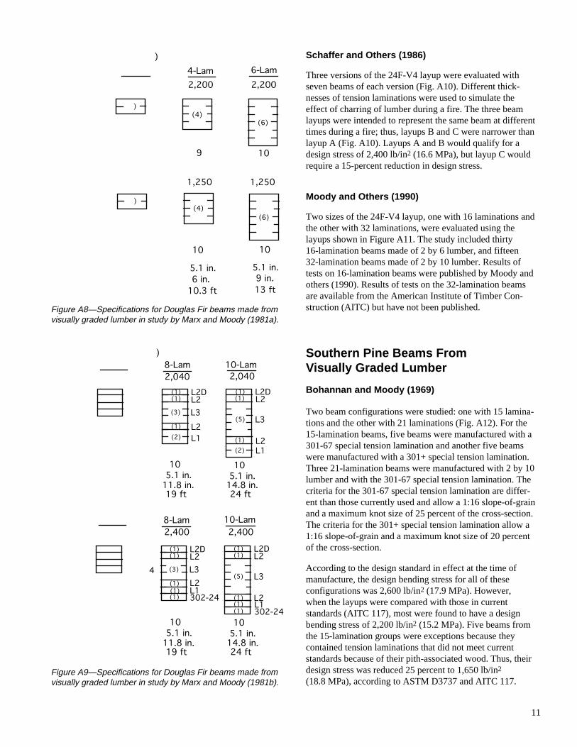
Marx and Moody (1981a)
Three sizes of shallow beams using either L1 or L3 lumberwere evaluated. Beam sizes were 2, 4, or 6 laminations deep,and the beams were made of uniform-grade material(Fig. A8). The design stresses for each beam size from table2 of AITC 117 are as follows:
L1 2,200 lb/in2 (15.2 MPa)
L3 1,250 lb/in2 (8.6 MPa)
Marx and Moody (1981b)
Six beam configurations using the 24F-V4 layup of AITC117 were evaluated, including three sizes of beams madeusing the layups shown in Figure A9. Ten beams wereincluded for each size-layup combination. For each beamsize, the design stress for those beams with special tensionlaminations was 2,400 lb/in2 (16.6 MPa). The design stressof beams with the L1 grade tension lamination was reducedby 15 percent (2,040 lb/in2 (14.1 MPa)) (ASTM D3737).
(2)
(8)
(1)
L2
L3No.3***
L2D301-22(1)
3.08 in.17.9 in.19 ft15
13-Lam2,200(2)
(2)
(6)
(1)
L2
L3
L3No.3**
L2D301-22(1)
3.08 in.17.9 in.19 ft14
13-Lam2,200(1)
(1)
lemann spruceemann spruce with wanelas Fir with wane
B C
11
Figure A8—Specifications for Douglas Fir beams made fromvisually graded lumber in study by Marx and Moody (1981a).
Figure A9—Specifications for Douglas Fir beams made fromvisually graded lumber in study by Marx and Moody (1981b).
Schaffer and Others (1986)
Three versions of the 24F-V4 layup were evaluated withseven beams of each version (Fig. A10). Different thick-nesses of tension laminations were used to simulate theeffect of charring of lumber during a fire. The three beamlayups were intended to represent the same beam at differenttimes during a fire; thus, layups B and C were narrower thanlayup A (Fig. A10). Layups A and B would qualify for adesign stress of 2,400 lb/in2 (16.6 MPa), but layup C wouldrequire a 15-percent reduction in design stress.
Moody and Others (1990)
Two sizes of the 24F-V4 layup, one with 16 laminations andthe other with 32 laminations, were evaluated using thelayups shown in Figure A11. The study included thirty16-lamination beams made of 2 by 6 lumber, and fifteen32-lamination beams made of 2 by 10 lumber. Results oftests on 16-lamination beams were published by Moody andothers (1990). Results of tests on the 32-lamination beamsare available from the American Institute of Timber Con-struction (AITC) but have not been published.
Southern Pine Beams FromVisually Graded Lumber
Bohannan and Moody (1969)
Two beam configurations were studied: one with 15 lamina-tions and the other with 21 laminations (Fig. A12). For the15-lamination beams, five beams were manufactured with a301-67 special tension lamination and another five beamswere manufactured with a 301+ special tension lamination.Three 21-lamination beams were manufactured with 2 by 10lumber and with the 301-67 special tension lamination. Thecriteria for the 301-67 special tension lamination are differ-ent than those currently used and allow a 1:16 slope-of-grainand a maximum knot size of 25 percent of the cross-section.The criteria for the 301+ special tension lamination allow a1:16 slope-of-grain and a maximum knot size of 20 percentof the cross-section.
According to the design standard in effect at the time ofmanufacture, the design bending stress for all of theseconfigurations was 2,600 lb/in2 (17.9 MPa). However,when the layups were compared with those in currentstandards (AITC 117), most were found to have a designbending stress of 2,200 lb/in2 (15.2 MPa). Five beams fromthe 15-lamination groups were exceptions because theycontained tension laminations that did not meet currentstandards because of their pith-associated wood. Thus, theirdesign stress was reduced 25 percent to 1,650 lb/in2
(18.8 MPa), according to ASTM D3737 and AITC 117.
)
5.1 in.9 in.13 ft
10
6-Lam2,200
5.1 in.6 in.10.3 ft
10
4-Lam2,200
1,2501,250
) (4) (6)
) (4) (6)
109
)
10-Lam2,4008-Lam2,400
10-Lam2,0408-Lam2,040
(3) (5)
1010 5.1 in.14.8 in.24 ft5.1 in.11.8 in.19 ft
1010 5.1 in.14.8 in.24 ft5.1 in.11.8 in.19 ft
(1)
(1)(2)
(1)(2)
(1)L3L2L1
L2DL3L2D
L1L2
(1) L2 (1) L2
(3) (5)
(1)
(1)(1)(1)(1)
(1)4 L3
L2L1
L2DL3L2D
L1L2
(1) L2 (1) L2
(1) 302-24(1) 302-24

12
Figure A10—Specifications for Douglas Fir beams madefrom visually graded lumber in study by Schaffer andothers (1986).
Figure A11—Specifications for Douglas Fir beamsmade from visually graded lumber in study by Moodyand others (1990).
Figure A12—Specifications for Southern Pine beamsmade from visually graded lumber in study byBohannan and Moody (1969).
Moody and Bohannan (1970b)
Five 16-lamination beams were evaluated with the layupshown in Figure A13. According to the 1970 standards, thesebeams had a design stress of 2,600 lb/in2 (17.9 MPa). Usingcurrent standards, the design stress would be 2,400 lb/in2
(16.6 MPa).
Moody and Bohannan (1971)
Ten beams were manufactured using the same layup as thatused in a previous study by these authors (Moody andBohannan 1970b) (Fig. A14). Five beams were manufac-tured with no finger joints near the midlength of the tensionlamination. For another five beams, specific gravity criteria,in addition to the visual criteria, were used to positionlaminations. All 10 beams had an applicable design bendingstress of 2,400 lb/in2 (16.6 MPa) by current standards.
Moody (1974b)
Two different 15-lamination beams were evaluated, with 10beams in each group, using the layups shown in Figure A15.Combination I was determined to be comparable to a layupwith a 1,600 lb/in2 (19 MPa) stress in the current standard.Combination II compared to a layup with a design stress of2,200 lb/in2 (15.2 MPa).
Wolfe and Moody (1979)
Vertically laminated beams made of No. 2D lumber and 1 to5 laminations were evaluated (Fig. A16). The data for beamswith 2 to 5 laminations were included in the data set. Thirty-six replicates were included for the 2-Lam samples and
86)10-Lam2,04011-Lam2,400
(5)
772.125 in.15 in.25.5 ft
3.625 in.15.75 in.25.5 ft
(5)
B C4
(1)(2)
(1)(1)(1)(1)
(1)(2)
(1) 302-24L1L2L3L2L2D
L1L2L3L2L2D
969)21-Lam2,200
9 in.31.5 in.48 ft3
15-Lam2,200
5.25 in.24 in.38 ft5
laminationsbteria had F
(17)(11)
(2)
(1)(1)
(2)
(1)(1)
No.2D
No.2
No.2DTL*
No.2D
No.2
No.2D301-67
)32-Lam2,400
8.75 in.48 in.64 ft
15
(18)-24
(3)(2)(2)
(3)(4)
L3
L2L1302-24
L2L2D

13
Figure A15—Specifications for Southern Pine beams madefrom visually graded lumber in study by Moody (1974b).
Figure A16—Specifications for Southern Pine beams madefrom visually graded lumber in study by Wolfe and Moody(1979).
30 replicates for each of the 3-, 4-, and 5-Lam groups. Theapplicable design stresses from table 2 of AITC 117 are asfollows: for 2-Lam beams, 1,500 lb/in2 (10.3 MPa); 3-Lam,1,800 lb/in2 (12.4 MPa); and 4- and 5-Lam, 2,000 lb/in2
(13.8 MPa).
Marx and Moody (1981a)
Three sizes of shallow beams using No. 2D lumber wereevaluated (Fig. A17). The beams were made of uniform-grade material. The design stress for each beam size wasfrom table 2 of AITC 117 (1,600 lb/in2 (18.8 MPa)).
Figure A13—Specifications for Southern Pine beamsmade from visually graded lumber in study by Moodyand Bohannan (1970b).
Figure A14—Specifications for Southern Pine beamsmade from visually graded lumber in study by Moodyand Bohannan (1971).
970b)16-Lam2,400
5.25 in.24 in.38 ft5
2
(12)
(1)(1)
(2)
No.2
No.1D301A-69
No.2D
.
(9)
17-Lam2,200
5 in.24 in.40 ft
10
tion I Combination II
(3)
(4)
(4)(1)(1)(1)
(1)(2)
(2)(2)
(2)(1)(1)
No.3C
No.2CNo.2M
No.2CNo.2D301-20
No.3CNo.2C
No.2CNo.2MNo.1D301-24
No.2MNo.1M
)
6.875 in.5.125 in.11 ft30
5-Lam2,000
5.5 in.5.125 in.11 ft30
4-Lam2,000
.125 in.125 in.11 ft30
-Lam,800(4)(3) (5)971)
2,400
5.25 in.24 in.38 ft
10
(2)
(12)
(1)
No. 2D
No. 2
No. 1D301A-69(1)
2

14
Figure A17—Specifications for Southern Pine beams madefrom visually graded lumber in study by Marx and Moody(1981a).
Figure A18—Specifications for Southern Pine beams madefrom visually graded lumber in study by Marx and Moody(1981b).
Marx and Moody (1981b)
Six beam configurations were evaluated: three beam sizes ofthe 24F-V2 combination from AITC 117–ManufacturingStandard (1988) and three beam sizes of the same combina-tion without a special tension lamination (Fig. A18). Theinitial study plan included 10 beams of each size-layupcombination. When the beams were evaluated, the authorsfound that the finger joints did not meet the ANSI A190.1standard for a 2,400 lb/in2 (16.6 MPa) design stress, butwould meet the standard for a lower design stress
)6-Lam1,600
4-Lam1,600
(2)(6)
1010in..ft5.1 in.9 in.13 ft
5.1 in.6 in.10.3 ft
(4)
(2,040 lb/in2 (14.1 MPa)). Thus, another complete set of10 beams for each size-layup combination was manufacturedand evaluated. For the analyses in this study, the beams thatcontained special tension laminations from the initial setwere removed from the data base because of the inadequacyof the finger joints. Therefore, the beams from the initial setthat did not have special tension laminations as well as theentire second set were included.
For each beam size, the design stress for those beams withspecial tension laminations would be 2,400 lb/in2 (16.6MPa). Beams with the No. 1D grade tension laminationswould have a design stress reduced by 15 percent or2,040 lb/in2 (14.1 MPa) (ASTM D3737).
Marx and Moody (1982)
All the beams in this study were made with four laminationsand complemented the beams in a previous study (Marx andMoody 1981b). One set of beams was made with an interme-diate grade of 2 by 6 tension lamination lumber, and threesets were made with 2 by 10 lumber. The sets made with2 by 10 lumber had three grades of tension laminations:No. 1D, 302-20, and 302-24 (Fig. A19).
The design bending stress for the beams with either the302-20 or 302-24 tension laminations was 2,400 lb/in2
(16.6 MPa); the design stress for the beams with No. 1Dtension laminations was 2,040 lb/in2 (14.1 MPa).
Gopu (1991)
The study evaluated fifteen 35-lamination beams of the24F-V3 layup (Fig. A20). The beams were made with 2 by10 lumber and the design stress was 2,400 lb/in2 (16.6 MPa).
Soltis and Rammer (1994)
Two sizes of beams made with the 24F-V5 layup wereevaluated, using 20 beams of each size (Fig. A21). The8-Lam beams were made from 2 by 4 lumber and the16-Lam beams were made from 2 by 6 lumber. The designstress was 2,400 lb/in2 (16.6 MPa).
Douglas Fir Beams FromE-Rated Lumber
Johnson (1969a)
A total of 11 beams were manufactured from E-rated lumbersimilar to the visually graded lumber used to manufacture thebeams studied by Bohannan and Moody (1969). For thelayup shown in Figure A22, the 15-lamination beams weretargeted to have a design stress in bending of 2,600 lb/in2
(17.9 MPa). The standard (AITC 117) does not providelayups for this design stress for E-rated Douglas Fir. How-ever, the layup (Fig. A22) would qualify for a design stressof 2,600 lb/in2 (17.9MPa) using the criteria of ASTMD3737. Thus, this design stress was used.
)
10-Lam2,4008-Lam
2,400
10-Lam2,0408-Lam2,040
(5) (7)
1010 5.0 in.15.0 in.24 ft5.0 in.12.0 in.19 ft
1010 5.0 in.15.0 in.24 ft5.0 in.12.0 in.19 ft
(1)
(1)(1)(1)(1)
(1)No.2MNo.2DNo.1D
No.1DNo.2MNo.1D
No.2DNo.1D
(5) (7)
(1)
(1)(1)(1)(1)
(1)4 No.2M
No.2D302-24
No.1DNo.2MNo.1D
No.2D302-24

15
Figure A19—Specifications for Southern Pine beamsmade from visually graded lumber in study by Marx andMoody (1982).
Two layups were evaluated, with six beams in each group(Fig. A23). The 16-lamination beams closely paralleled thelayups in the current standard for a 2,200 lb/in2 (15.2 MPa)or 2,400 lb/in2 (16.6 MPa) design stress in bending. Layupsfor 2,600 lb/in2 (17.9 MPa) are not given for E-rated DouglasFir in AITC 117. However, the 26F layup would qualify forthis design stress value using the criteria of ASTM D3737.Thus, this design stress was used for the 26F layup.
Moody (1977)
A total of 15 beams were manufactured from E-rated 2 by 4lumber using the layup shown in Figure A24. The lumbermet the requirements of layup 24F-E5, so the applicabledesign stress was 2,400 lb/in2 (16.6 MPa).
Wolfe and Moody (1978)
The Douglas Fir beam combination used for this study wasthe same as the combination in the study by Moody (1977)(Fig. A24). The beams were immersed in water for severalweeks and then tested to failure in bending to determine theeffect of high moisture content. This beam combination wasassigned a 2,400 lb/in2 design stress in bending, as was thegroup E combination from Moody (1977). Reduction indesign bending stress resulting from high moisture contentwas accounted for by the 0.8 end-use factor for moisturecontent (Cm), which reduced the design bending stressto 1,920 lb/in2.
Figure A20—Specifications for Southern Pine beamsmade from visually graded lumber in study by Gopu (1991).
Southern Pine BeamsFrom E-Rated Lumber
Johnson (1969b)
Two layups were evaluated, with six beams in each group(Fig. A25). The 16-lamination beams closely paralleled thecurrent layups in AITC 117 for a 2,200 lb/in2 (15.2 MPa) or2,400 lb/in2 (16.6 MPa) design stress in bending. Layups for2,600 lb/in2 (17.9 MPa) are not given for E-rated SouthernPine in AITC 117. However, the 26F layup would qualify fora design stress of 2,600 lb/in2 (17.9 MPa) using the criteriaof ASTM D3737. Thus, this design stress was used.
4-Lam2,040
108.75 in6 in9.5 ft
20(1)(1)(2)
No.1DNo.1DNo.2M
4-Lam2,400
108.75 in.6 in.9.5 ft
(1)(1)(2)
No.1D302-24No.2MD
-20M
35-Lam2,400
(19)
8.5 in.49 in.64 ft15(2)(2)
(5)
(3)
(4)
No.2M
302-24No.1D
No.2D
No.2D
No.1D

16
Figure A21—Specifications for Southern Pine beamsmade from visually graded lumber in study by Soltisand Rammer (1994).
Figure A22—Specifications for Douglas Fir beams madefrom E-rated lumber in study by Johnson (1969a).
Moody (1977)
A total of 15 beams were manufactured from E-rated 2 by 4lumber using the layup shown in Figure A26. The lumberused in the beams closely approximated the requirements oflayup 22F-E2 of AITC 117, so the applicable design stresswas 2,200 lb/in2 (15.2 MPa).
Figure A23—Specifications for Douglas Fir beamsmade from E-rated lumber in study by Johnson (1969b).
Figure A24—Specifications for Douglas Fir beamsmade from E-rated lumber in study by Moody (1977).
Hernandez and Moody (1992)
The beam configurations were new layups with a targetdesign bending stress of 3,000 lb/in2 (20.7 MPa) and designmodulus of elasticity (MOE) of 2,000,000 lb/in2 (13.8 GPa)(Fig. A27). The 2.3E material was sorted for stiffness from apopulation of visually graded No. 1D material. The No. 1Dmaterial used in manufacture of the beams was sorted toassure that it had an average MOE of 2,000,000 lb/in2
(13.8 GPa) to correspond with the industry design value forthis grade. Twenty beams of each configuration wereevaluated.
4)16-Lam2,400
5 in.22 in.40 ft20
(10)
(1)(1)(1)
(1)(1)(1)24
24 No.2M
No.2DNo.1D302-24
302-24No.1DNo.2D
16-Lam2,600
5 in.23.5 in.38 ft
6
(8)
(2)(2)
(2)(2)
-1/4-1/6
L3
2.0E2.4E
2.0E-1/62.4E-1/6
-Lam2,400
.08 in.2.4 in.19 ft
15(1)
(6)
(1) 2.0E
L32.0E-1/6(1) 2.2E-1/6
15-Lam2,600
5.2 in.24 in.38 ft
11
(5)
(1)(1)(1)(2)
(2)(2)
(1)
L2 and L31.7E1.8 to 2.2E2.0 to 2.2E2.3 to 2.5E
2.2 to 2.3E2.5 to 2.7E1.7E
2

17
Figure A25—Specifications for Southern Pine beamsmade from E-rated lumber in study by Johnson (1969b).
Figure A26—Specifications for Southern Pine beamsmade from E-rated lumber in study by Moody (1977).
Wolfe and Moody (1978)
The Southern Pine beam combination used for this study wasthe same as the combination in the study by Moody (1977)(Fig. A26). The beams were immersed in water for severalweeks and then tested to failure in bending to determine theeffect of high moisture content. This beam combination wasassigned a 2,000 lb/in2 (13.8 MPa) design stress in bending,as was the group F combination from Moody (1977).Reduction in design bending stress resulting from highmoisture content was accounted for by the 0.8 end-use factorfor moisture content (Cm), which reduced the design bendingstress to 1,760 lb/in2 (12.1 MPa).
Figure A27—Specifications for Southern Pine beamsmade from E-rated lumber in study by Hernandez andMoody (1992).
Douglas Fir Beams FromProof-Loaded, E-Rated Lumber
Pellerin and Strickler (1971)
Three beams each of three 7-lamination layups were evalu-ated (Fig. A28). The layups differed in the stiffness oflumber selected for the L1 and L2 zones and were designatedas 2200f, 2400f, and 2600f. Before beam manufacture, thetwo outer laminations on the tension side were proof-loadedin tension to 1.4 times their nominal stress at the design load.Findings of this and later studies, summarized in Table A1,suggest that the applicable design stresses for the 2200f,2400f, and 2600f layups should be 2.4, 2.6, and2.6 × 103 lb/in2 (16.6, 17.9, and 17.9 MPa), respectively.
Strickler and Pellerin (1971)
Six beams each of three layups were evaluated (Fig. A29).The layups differed in the stiffness of lumber selected for theL1 and L2 zones and were designated as L, M, and H. Beforebeam manufacture, the four outer laminations on the tensionsize were proof-loaded in tension. Findings of this and laterstudies, summarized in Table B1, suggest that the applicabledesign stresses for the L, M, and H layups should be 2.4, 2.6,and 2.6 × 10³ lb/in2 (16.6, 17.9, and 17.9 MPa), respectively.
Pellerin and Strickler (1972)
Six beams each of four layups were evaluated (Fig. A30).The lumber was arranged with stiffer lumber in the outerzones. The layups differed in the stiffness of lumber selectedfor the various zones and in the proof-load level used.
992)
)
17-Lam3,000
5 in.23.4 in.40 ft20
(7)
(3)(1)(1)
(3)(2))
.2M3E. 1D
2-22 No.2M
No.1D302-30
)
)) . 1D
2.3ENo. 1D
2.3E
16-Lam2,600
5 in.23.5 in.38 ft6
(8)
(2)(2)
(2)(2)
. 2
8E0E
8E-1/40E-1/6
No. 2
1.8E2.2E
1.8E-1/42.2E-1/6
-Lam,200
.14 in.2.4 in.19 ft
15(1)
(6)
(1) 1.8ENo.21.8E-1/6(1) 2.0E-1/6

18
Figure A28—Specifications for Douglas Fir beamsmade from proof-loaded, E-rated lumber in study byPellerin and Strickler (1971).
Figure A29—Specifications for Douglas Fir beamsmade from proof-loaded, E-rated lumber in studyby Strickler and Pellerin (1971).
Layups B1 and B2 were designed for 2.2 × 10³ lb/in2 (15.2MPa); layups A1 and A2 were designed for 2.6 × 10³ lb/in2
(17.9 MPa). The outer two laminations on the tension sidewere proof-loaded in tension prior to beam manufacture. Aproof-load level of 1.4 times the nominal stress at designload was used for layups A1 and B1. For layups A2 and B2,the level was 1.2 times the nominal stress at design load.Findings of this and later studies, summarized in Table B1,suggest that the applicable design stresses for the layups are
Figure A30—Specifications for Douglas Fir beamsmade from proof-loaded,E-rated lumber in studyby Pellerin and Strickler (1972).
2.6 × 10³ lb/in2 (17.9 MPa) for layup A1 and 2.4 × 10³ lb/in2
(16.6 MPa) for the other three layups.
Strickler and Pellerin (1974)
Six beams each of nine layups were evaluated (Fig. A31).The visual grades of the layups followed one of two 16-lamination layups, and the lumber was arranged with stifferlumber in the outer zones. The layups differed in the stiffnessof lumber selected for the various laminations, in the proof-load level used, and in the number of proof-loaded lamina-tions. Four layups (A3, A6, B3, and B4) were similar tothose from the research reported by these authors in 1972except that the outer three laminations on the tension side,rather than two laminations, were proof loaded. One layup(A7) had four proof-loaded laminations. Proof-loads differ-ent from those used in earlier studies were used for twolayups (A4 and A5), and higher stiffness lumber was usedfor another two layups (C1 and C2). Findings of this andlater studies suggest that the applicable design stresses forthe layups are as follows: A3, A7, B3, and B4, 2,400 lb/in2
(16.6 MPa); A4, A5, A6, and C1, 2,600 lb/in2 (17.9 MPa);and C2, 2,800 lb/in2 (19.3 MPa).
71)
7-Lam2,600
7-Lam2,600
33
(3)(1)(1)
(1)(1)L3 (3)
(1)(1)
(1)(1)L3
2400f 2600f
5.25 in. 5.25 in.10.5 in. 10.5 in.16 ft 16 ft
inations were tension proof .4 times design stresser sorted from L1 gradeer sorted from L2 grade
2.1E*
2.4E*1.8E**1.7E** 2.3E*
3.0E*2.1E**2.2E**
71)12-Lam2,60012-Lam2,600
66 5.25 in.16 in.23 ft5.25 in.16 in.23 ft
6-2.0E*
8-2.2E*3-1.8E**
3-1.6E**
M H
(2)(2) 2.0-2.3E*
2.2-2.5E*1.8-2.0E**
1.6-1.8E**L3(4)
(2)(2)
(2)(2) 2.3-2.6E*
2.5-3.0E*2.0-2.4E**
1.8-2.3E**L3(4)
(2)(2)
minations were tension proof 1.4 times design stresser sorted from L1 gradeer sorted from L2 grade
72)
-1.7E**
-2.3E**
16-Lam
(2)
Combination 2
(8)
tions were tension proof loaded as follows: 1, Group B1 = 1.4 times design stress 1, Group B2 = 1.2 times design stress 2, Group A1 = 1.4 times design stress 2, Group A2 = 1.2 times design stress
(2)
(2)(2)
125.125 in.24 in.38 ft
orted from L1 and L2 gradeorted from L2 and L3 grade
-1.9E**
-1.9E**-2.3E**
1.0-1.7E**
2.1-2.7E**1.8-2.1E**
1.8-2.1E**2.1-2.7E**
A1 = 2,600A2 = 2,400

19
Figure A31—Specifications for Douglas Fir beamsmade from proof-loaded, E-rated lumber in studyby Strickler and Pellerin (1974).
Southern Pine Beams FromProof-Loaded, E-Rated LumberStrickler and Pellerin (1976)
Six beams each of four layups, designated X1, Y1, Y2, andZ1, were evaluated (Fig. A32). The lumber was arrangedwith stiffer lumber in the outer zones. The layups differed inthe stiffness of lumber selected for the various zones and inthe proof-load level used. The outer three laminations on thetension side were each proof-loaded in tension to differentlevels for each layup. Using the results of this and thefollowing study, which are summarized in Table B1, thedesign stresses for X1, Y1, Y2, and Z1 were 2,200, 2,400,2,400, and 2,600 lb/in2 (15.2, 16.6, 16.6, and 17.9 MPa),respectively.
Pellerin and Strickler (1977)
Six beams each of four layups, designated X2, Y3, Y4, andZ2, were evaluated (Fig. A33). The lumber was arrangedwith stiffer lumber in the outer zones. The layups differed inthe stiffness of lumber selected for the various zones and inthe proof-load level used. The outer three laminations on thetension side were each proof-loaded in tension prior to beammanufacture. Using the results of this and the previous studygiven in Table A1, the design stresses for X2, Y3, Y4, andZ2 were 2,400, 2,600, 2,800, and 3,000 lb/in2 (16.6, 17.9,19.3, and 20.7 MPa), respectively.
References
AITC. 1987. Laminating specifications. AITC 117–Design.Vancouver, WA: American Institute of Timber Construction.
AITC. 1988. Manufacturing standard specification forstructural glued laminated timber of softwood species. AITC117–Manufacturing. Vancouver, WA: American Institute ofTimber Construction.
Bohannan, B. 1966. Flexural behavior of large glued-laminated beams. Res. Pap. FPL–RP–72. Madison, WI: U.S.Department of Agriculture, Forest Service, Forest ProductsLaboratory.
Bohannan, B.; Moody, R.C. 1969. Large glued laminatedtimber beams with two grades of tension laminations. Res.Pap. FPL–RP–113. Madison, WI: U.S. Department ofAgriculture, Forest Service, Forest Products Laboratory.
Gopu, V.K.A. 1991. Evaluation of large Southern Pineglulam timber beams. Report to AITC Task Committee onResearch. Vancouver, WA: American Institute of TimberConstruction.
Hernandez, R.; Moody, R.C. 1992. Development of highperformance Southern Pine structural glued-laminatedtimber. Res. Pap. FPL–RP–514. Madison, WI: U.S. Depart-ment of Agriculture, Forest Service, Forest ProductsLaboratory.
74)Group B3
Bottom 3 Lamsproof tested to 2640 lb/in2
Bottom 3 Lamsproof tested to 3120 lb/in2
3640 lb/in2
Group C1Bottom 2 Lamsproof tested to
2,600 lb/in2F :b
Group C2Bottom 2 Lamsproof tested to 3920 lb/in2
2,800 lb/inF :b 2
2,400 lb/in2F :b
Group B42,400 lb/in 2F :b
Bottom 4 Lamsproof tested toGroup A7
3120 lb/in2
2,400 lb/inF : 2b
Group A5Bottom 3 Lamsproof tested to 3380 lb/in2
2,600 lb/in2F :bGroup A6
Bottom 3 Lamsproof tested to2,600 lb/inF : 2b
3640 lb/in2
Group A3Bottom 3 Lamsproof tested to
2,400 lb/in2F :b
3120 lb/in2
Group A4Bottom 2 Lamsproof tested to
2,600 lb/in2F :b
3380 lb/in2

20
Figure A32—Specifications for Southern Pine beamsmade from proof-loaded, E-rated lumber in study byStrickler and Pellerin (1976).
Figure A33—Specifications for Southern Pine beamsmade from proof-loaded, E-rated lumber in study byPellerin and Strickler (1977).
76)
s were tension proof loaded as follows: times design stress times design stress times design stress times design stress
18-Lam2,400Y1
.0-1.7E****
.9-2.15E***
.7-1.9E***
.7-1.9E**
.9-2.15E*
1.0-1.7E****
2.15`-2.4E***1.9-2.15E***
1.9-2.15E**2.15-2.4E*
(2)
(10)
(1)(3)
(2)
65 in.24 in.38 ft
18-Lam2,600Z1
.0-1.7E****
.15-2.4E***
.9-2.15E***
.9-2.15E**
.15-2.4E*
1.0-1.7E****
2.15`-2.4E**2.4-3.0E*
(2)
(10)
(1)(3)
(2)
65 in.24 in.38 ft
ed from No. 1 gradeed from No. 2 gradeed from No. 3 and Better gradeed from No. 3 grade
2.15-2.4E***2.4-3.0E***
77)
tension proof loaded to 1.5 times design stress
17-Lam2,600Y3
.0-1.7E**
.9-2.15E***
.7-1.9E**
.7-1.9E**
.9-2.15E*
1.0-1.7E**
2.15`-2.4E***1.9-2.15E**
1.9-2.15E**2.15-2.4E*
(2)
(9)
(1)(3)
(2)
65.1 in.23.375 in.38 ft
17-Lam3,000Z2
.0-1.7E**
.15-2.4E***
.9-2.15E**
.9-2.15E**
.15-2.4E*
1.0-1.7E**
2.15-2.4E**2.4-3.0E*
(2)
(9)
(1)(3)
(2)
65.1 in.38 ft
ed from No. 1 gradeed from No. 2 gradeed from No. 2 and Better grade
2.15-2.4E**2.4-3.0E***
23.375 in.

21
Johnson, J.W. 1969a. Flexural tests of large glued-lami-nated beams made of nondestructively tested lumber. ReportT–26. Corvallis, OR: Forest Research Laboratory, School ofForestry, Oregon State University.
Johnson, J.W. 1969b. Flexural tests of large glued-lami-nated beams made of nondestructively tested lumber. ReportT–27. Corvallis, OR: Forest Research Laboratory, School ofForestry, Oregon State University.
Marx, C.M.; Moody, R.C. 1981a. Bending strength ofshallow glued-laminated beams of a uniform grade. Res.Pap. FPL–RP–380. Madison, WI: U.S. Department ofAgriculture, Forest Service, Forest Products Laboratory.
Marx, C.M.; Moody, R.C. 1981b. Strength and stiffness ofsmall glued-laminated beams with different qualities oftension laminations. Res. Pap. FPL–RP–381. Madison, WI:U.S. Department of Agriculture, Forest Service, ForestProducts Laboratory.
Marx, C.M.; Moody R.C. 1982. Effect of lumber width andtension lamination quality on the bonding strength of four-ply laminated beams. Forest Products Journal. 32(1): 45–52.
Moody, R.C. 1974a. Design criteria for large structuralglued-laminated timber beams using mixed species ofvisually graded lumber. Res. Pap. FPL–RP–236. Madison,WI: U.S. Department of Agriculture, Forest Service, ForestProducts Laboratory.
Moody, R.C. 1974b. Flexural strength of glued-laminatedtimber beams containing coarse-grain Southern Pine lumber.Res. Pap. FPL–RP–222. Madison, WI: U.S. Department ofAgriculture, Forest Service, Forest Products Laboratory.
Moody, R.C. 1977. Improved utilization of lumber in gluedlaminated beams. Res. Pap. FPL–RP–292. Madison, WI:U.S. Department of Agriculture, Forest Service, ForestProducts Laboratory.
Moody, R.C.; Bohannan, B. 1970a. Large glued-laminatedbeams with AITC 301A–69 grade tension laminations.Res. Pap. FPL–RP–146. Madison, WI: U.S. Department ofAgriculture, Forest Service, Forest Products Laboratory.
Moody, R.C.; Bohannan, B. 1970b. Flexural properties ofglued-laminated Southern Pine beams with laminationspositioned by visual-stiffness criteria. Res. Pap.FPL–RP–127. Madison, WI: U.S. Department ofAgriculture, Forest Service, Forest Products Laboratory.
Moody, R.C.; Bohannan, B. 1971. Flexural properties ofglued-laminated Southern Pine beams—finger joint andspecific gravity effects. Res. Pap. FPL–RP–151. Madison,WI: U.S. Department of Agriculture, Forest Service, ForestProducts Laboratory.
Moody, R.C.; Falk, R.H.; Williamson, T.G. 1990. Strengthof glulam beams—Volume effects. In: Proceedings of the1990 International Timber Engineering Conference; 1990;Tokyo. 1: 176–182.
Pellerin, R.F.; Strickler, M.D. 1971. Tension proof loadingof lam stock for laminated beams. Forest Products Journal.21(5): 50–55.
Pellerin, R.F.; Strickler, M.D. 1972. Proof loading oftension laminations for large glued laminated beams. ForestProducts Journal. 22(10): 24–30.
Pellerin, R.F.; Strickler, M.D. 1977. Southern Pine beamsfrom E-rated and proof loaded lumber. Proc. Pap. 1049.American Society of Civil Engineers. Journal of theStructural Division of ASCE. 1103(ST1): 270–274.
Schaffer, E.L.; Marx, C.M.; Bender, D.A.; Woeste, F.E.1986. Strength validation and fire endurance of glued-laminated timber beams. Res. Pap. FPL–RP–467. Madison,WI: U.S. Department of Agriculture, Forest Service, ForestProducts Laboratory.
Soltis, L.; Rammer, D. 1994. Experimental shear strengthof glued-laminated beams. Res. Pap. FPL–RP–527. Madison,WI: U.S. Department of Agriculture, Forest Service, ForestProducts Laboratory.
Strickler, M.D.; Pellerin, R.F. 1971. Tension proof loadingof finger joints for laminated beams. Forest Products Journal.21(6): 19–24.
Strickler, M.D.; Pellerin, R.F. 1974. Glued-laminatedDouglas Fir beams from E-rated and tension proof loadedlumber. Bull. 337. Pullman, WA: Washington StateUniversity, College of Engineering.
Strickler, M.D.; Pellerin, R.F. 1976. Tension proof loadingfor Southern Pine beams. Proc. Pap. 11978. AmericanSociety of Civil Engineers. Journal of the StructuralDivision of ASCE. 102(ST3): 645–657.
Western Wood Products Association. 1991. Westernlumber grading rules. Portland, OR: Western Wood ProductsAssociation.
West Coast Lumber Inspection Bureau. 1991. Standardgrading rules for West Coast lumber. Portland, OR: WestCoast Lumber Inspection Bureau.
Wolfe, R.W.; Moody, R.C. 1978. Bending strength ofwater-soaked glued laminated beams. Res. Pap. FPL–RP–307. Madison, WI: U.S. Department of Agriculture, ForestService, Forest Products Laboratory.
Wolfe, R.W.; Moody, R.C. 1979. Bending strength ofvertically glued laminated beams with one to five plies.Res. Pap. FPL–RP–333. Madison, WI: U.S. Department ofAgriculture, Forest Service, Forest Products Laboratory.

22
Appendix B—SupplementalInvestigation on Volume Effects
As noted, AITC currently specifies that the end-use factor Cvshould be used for all depths greater than 12 in. (30.48 cm).For depths shallower than 12 in. (30.48 cm), the Cv islimited to a maximum value of 1.0. The issue of limitingCv values to 1.0 for shallow beams is addressed first. FiguresA1 and A2 show calculated K values for the Douglas Firbeams fabricated with visually graded lumber. Figure A1applies the current AITC rule ( Cv = 1.0) for beam depthsshallower than 12 in. (30.48 cm) and Figure A2 applies thecalculated volume factors throughout all depths. Similarplots for Southern Pine beams made from visually gradedlumber are illustrated in Figures A3 and A4; Figure A3shows Cv = 1.0, and Figure A4 shows Cv applied through-out all depths. Table A1 summarizes the calculated K valuesfor these beam groups.
The results from this initial analysis indicated that whenthevolume effect factor was applied throughout all beamdepths, the average K value for each beam depth remainedfairly constant in relation to the overall mean K value of thegroup. When the current AITC rule for shallow beams wasapplied (Cv = 1.0), the calculated K values for the shallowerbeams were significantly greater. As a result of applying theAITC rule, average K values for each beam depth werehighly scattered around the overall mean of the group; theaverage K values were approximately 6 percent higher forboth species compared with groups in which Cv was appliedthroughout all depths. The results of this analysis suggestthat all beams be analyzed by applying Cv over all depths;this was done for all remaining analyses.
Figure B1—Calculated K-factors for horizontally laminatedDouglas Fir beams made from visually graded lumber.(Volume effect factor equal to 1.0 for beams ≤12 in. deep.)
Figure B2—Calculated K-factors for horizontally laminatedDouglas Fir beams made from visually graded lumber.(Volume effect factor applied to all depths.)
Figure B3—Calculated K-factors for horizontally laminatedSouthern Pine beams made from visually graded lumber.(Volume effect factor equal to 1.0 for beams ≤12 in. deep.)
Figure B4—Calculated K-factors for horizontally laminatedSouthern Pine beams made from visually graded lumber.(Volume effect factor applied to all depths.)
7
6
5
4
3
2
1
K-f
acto
r
Beam depth (in.)
0 6 12 18 24 30 36 42 48 54
If depth <12 in., Cv = Cv
Sample size = 372Average = 2.985
7
6
5
4
3
2
1
K-f
acto
r
Beam depth (in.)
0 6 12 18 24 30 36 42 48 54
If depth <12 in., Cv = 1.0Sample size = 372
Average = 3.2107
6
5
4
3
2
1
K-f
acto
r
Beam depth (in.)
0 6 12 18 24 30 36 42 48 54
If depth <12 in., Cv = Cv
Sample size = 262Average = 2.902
7
6
5
4
3
2
1
K-f
acto
r
Beam depth (in.)
0 6 12 18 24 30 36 42 48 54
If depth <12 in., Cv = 1.0Sample size = 262
Average = 2.994

23
Table B1—K-factor results for volume effect studya
Douglas Fir Southern Pine Combined
Volume factor Avg. COV Avg. COV Avg. COV
Cv = 1.0 for d < 12 in.b 3.210 26.7 2.994 22.6 3.121 25.5
Cv applied at all depthsc 2.985 22.8 2.902 21.5 2.951 22.3
Difference between average values (%) 7.5 3.2 5.8
aAll beams were horizontally laminated with visually graded lumber. COV is coefficient of variation (%).bThe AITC rule was applied for depths shallower than 12 in. (30.48 cm). cThe volume effect factor was used for all depths.