Embed Size (px)
Citation preview
infrastructures
Review
Fiber Optics Sensors in Asphalt Pavement:State-of-the-Art Review
Patricia Kara De Maeijer 1,* , Geert Luyckx 2, Cedric Vuye 1 , Eli Voet 2, Wim Van den bergh 1,Steve Vanlanduit 3, Johan Braspenninckx 4, Nele Stevens 4 and Jurgen De Wolf 5
1 EMIB Research Group, Faculty of Applied Engineering, University of Antwerp, 2020 Antwerp, Belgium;[email protected] (C.V.); [email protected] (W.V.d.b.)
2 Com&Sens, 9810 Nazareth, Belgium; [email protected] (G.L.); [email protected] (E.V.)3 Op3Mech Research Group, Faculty of Applied Engineering, University of Antwerp, Groenenborgerlaan 171,
2020 Antwerp, Belgium; [email protected] Port of Antwerp, Zaha Hadidplein 1, 2030 Antwerp, Belgium;
[email protected] (J.B.); [email protected] (N.S.)5 Agency for Roads and Traffic, 1140 Evere, Belgium; [email protected]* Correspondence: [email protected]; Tel.: +32-3-265-8851
Received: 15 May 2019; Accepted: 14 June 2019; Published: 20 June 2019�����������������
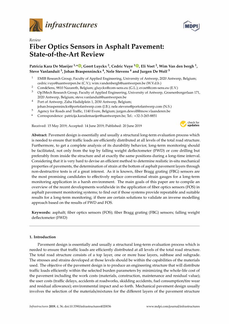
Abstract: Pavement design is essentially and usually a structural long-term evaluation process whichis needed to ensure that traffic loads are efficiently distributed at all levels of the total road structure.Furthermore, to get a complete analysis of its durability behavior, long-term monitoring shouldbe facilitated, not only from the top by falling weight deflectometer (FWD) or core drilling butpreferably from inside the structure and at exactly the same positions during a long-time interval.Considering that it is very hard to devise an efficient method to determine realistic in-situ mechanicalproperties of pavements, the determination of strain at the bottom of asphalt pavement layers throughnon-destructive tests is of a great interest. As it is known, fiber Bragg grating (FBG) sensors arethe most promising candidates to effectively replace conventional strain gauges for a long-termmonitoring application in a harsh environment. The main goals of this paper are to compile anoverview of the recent developments worldwide in the application of fiber optics sensors (FOS) inasphalt pavement monitoring systems; to find out if those systems provide repeatable and suitableresults for a long-term monitoring; if there are certain solutions to validate an inverse modellingapproach based on the results of FWD and FOS.
Keywords: asphalt; fiber optics sensors (FOS); fiber Bragg grating (FBG) sensors; falling weightdeflectometer (FWD)
1. Introduction
Pavement design is essentially and usually a structural long-term evaluation process which isneeded to ensure that traffic loads are efficiently distributed at all levels of the total road structure.The total road structure consists of a top layer, one or more base layers, subbase and subgrade.The stresses and strains developed at those levels should be within the capabilities of the materialsused. The objective of the pavement design is to produce an engineering structure that will distributetraffic loads efficiently within the selected burden parameters by minimizing the whole-life cost ofthe pavement including the work costs (materials, construction, maintenance and residual value);the user costs (traffic delays, accidents at roadworks, skidding accidents, fuel consumption/tire wearand residual allowance); environmental impact and so forth. Mechanical pavement design usuallyinvolves the selection of the materials/mixtures for the different layers of the pavement structure
Infrastructures 2019, 4, 36; doi:10.3390/infrastructures4020036 www.mdpi.com/journal/infrastructures
Infrastructures 2019, 4, 36 2 of 16
and the calculation of the required thickness of the designed pavement. Stiffness is a fundamentaland important parameter that must be fully understood in the selection of the materials. Usuallypavement layers have a higher stiffness while the layers underneath such as base and subbase have agreater thickness with a lower stiffness to get the same pressure on the underside. The thickness ofthe pavement structure layers can be reduced by increasing the stiffness of the layers and introducingmultilayered pavement structures which are commonly used in, for example, Belgium, France and TheNetherlands. One of the important facets of material behavior is the consideration of the situationwhere the layers are susceptible to moisture. If the area becomes saturated, the stiffness is reduced(normally imposed stresses taken by the dry material cause the layer to fail). For sure it can be avoidedif drainage is installed in such a way that groundwater never reaches the pavement layers. Sincemoisture may affect the subgrade and the sub-base (and, also the base if it is unbound). Another one isa temperature monitoring, as temperature affects the bitumen-bound layers. It is essential that thedesign process takes the climatic conditions into account [1,2]. Also, the pavement compaction qualityis a very important facet.
In the last 50 years, pavement research and related pavement techniques have grown. Thesetheories, principles, and/or procedures which were based on the knowledge and research achievementsat that time, have helped the pavement professionals to make specific analysis, design, construction andmaintenance on pavements. Therefore, they have created a far-reaching influence on later pavementtechnology [3]. On the other hand, during the same period, a lot of new pavement materials wereinvented and widely used. The properties of these new materials are considerably different comparedto the conventional materials. Neither traditional pavement analysis methods nor existing designprinciples can provide a direct way to consider these differences. This leads to the necessity andthe difficulty of modifying the pavement design methods used so far. Currently, there are severalimportant challenges to pavement research related to asphalt pavement analysis and design thatinclude: how to deal with more and more common heavy traffic loads (the allowed max. weight for 5axles to be 44 tons in Belgium and France and 50 tons in The Netherlands) [4], or even overloads andwith increasing traffic volumes; how to consider emerging pavement materials; how to incorporatenew materials, new techniques and new design concepts into pavement analysis and design; and howto consider ageing and healing effects.
The assessment of pavement mechanical state and service life is very important for designevaluation and road maintenance. However, this job seems to be a mission impossible, because itis unimaginable to learn how exactly a pavement works inside [5]. Conventional monitoring andinvestigation methods adopted by researchers are core drilling, pavement cutting, Benkelman beam,falling weight deflector (FWD), automatic deflectometer, surface-curvature apparatus and so forth.They are either destructive or with low-precision or low-frequency and most important is that all thesemethods are discontinuous and short-term. A pavement which is exposed for a long time to a naturalenvironment, is deteriorating at the coupled effect of load, temperature, water and ultraviolet light. Itis very difficult to completely understand the mechanical response of a pavement structure in an actualenvironment by regular methods [5]. In fact, pavement monitoring is a rather complicated process andeach pavement is another case to survey. Furthermore, it cannot be monitored only for a short-termperiod to get a complete analysis of the pavement behavior.
The past two decades some major technological breakthroughs produced by the fusion of differentdisciplines have been witnessed. This trend is likely to develop in the future due to the recent significantadvancements of fiber optics communications, photonics, biomedical and nanotechnologies worldwide.In parallel with the communications and information technology revolution, fiber and waveguideoptics sensor and imaging technologies have enjoyed an unseen technological maturity and revealedenormous potentials for a broad variety of new applications [6].
Asphalt material is often considered to behave in a linearly viscoelastic-plastic manner; thus,its mechanical response is a continuous function of time and temperature. Considering the stiffnessof the material, its behavior at lower temperatures is equivalent to a higher strain rate, such as the
Infrastructures 2019, 4, 36 3 of 16
strain on pavement due to fast moving traffic. In the case of high stiffness, the strain on asphaltshould ideally be measured directly for the greatest accuracy; however, instruments capable of makingsuch measurements are not generally available. Electrical strain gauges are often assumed to havenegligible stiffness and the stress transferred from the asphalt to an embedded sensor decreasesdrastically, thereby reducing the sensitivity of the sensor reading [7]. The sensors used for pavementinstrumentation must be as much compatible with the heterogeneous nature and mechanical propertiesof pavement materials. First, the sensors should be as small as possible so that they are not toointrusive in the bituminous layers. Secondly for strain measurements, the stiffness of the sensors hasto match that of the asphalt mixture in order to correctly measure the mechanical properties of thepavement. More-over, the embedded sensors must withstand the highest stresses experienced duringthe pavement construction process (high temperature and compression). After that, if a long-termmonitoring is considered, the sensor should be resistant to corrosion and to thermo-mechanical fatigueconditions [8].
Several fiber optic sensor technologies (fiber Bragg grating (FBG) and Fabry-Perot (FP)interferometry) have already been used for the experimental investigation of pavement behavior andpavement monitoring with positive results. FBG is a small portion of an optical fiber several millimeterslong in which a diffraction grating is written by ultraviolet (UV) exposure. The optical property of thisgrating is to reflect a narrow optical band (around a center wavelength called Bragg wavelength) of theincident spectrum. FBG have the intrinsic quality to be very sensitive to thermal and mechanical stimuli.The Bragg wavelength is proportional to the temperature and/or strain variation. Since, this sensor isvery brittle, it needs to be packaged. The fiber FP sensor is essentially an optical cavity that is definedby two semi-reflecting parallel mirrors. The FP cavity (at least in a bulk optic form) has highly reflectingmirrors of reflectivity such that the device has a high finesse and consequently its reflection/transmissionis spectrally selective and serves as an interference filter element. In its use with optical fibers, the cavityis formed in a short length (1–30 mm) of optical fiber that has partially reflecting coated ends whichis then fusion-spliced onto the end of the connecting fiber [9]. Those technologies allow to performdynamic measurements at a sampling rate of at least of 0.5–1 kHz (for the standard interrogators),they are investigated particularly for the development of traffic classification and weigh-in-motionsystems. In particular, FBG sensors have been widely applied in different sensing fields, where theyare used as strain and temperature sensors [10–13], for deformation investigation [14–16], ruttingperformance [17,18], response of asphalt concrete [19,20] and weigh-in-motion [21]. Compared withconventional sensors, FBG sensors are the most promising candidates to effectively replace conventionalstrain gauges for long-term real-time monitoring applications in a harsh environment. They exhibitseveral advantages: flexibility, embeddability, high frequency, electromagnetic interference immunityand so forth. FBG and FP technologies deliver a strain local measurement like an electrical strain gauge.Despite their high sensitivity and accuracy, they are not suitable for detection of cracks or damage.Due to their relatively small dimensions compared to those of a pavement, a crack can be detectedonly if it propagates in the vicinity of the sensor, by means of fiber optic sensing techniques based onthe Brillouin scattering or the Rayleigh scattering [8].
The FBG monitoring system prototype installed at UAntwerp—a three-layered pavement testtrack (width—4 m and length—96 m), the CyPaTs bicycle path—in September 2017, proved that theFBG technique can be successfully applicable for in-situ strain and temperature measurements underreal heavy loaded traffic (e.g., truck, paver, roller) in the asphalt pavement structures during the asphaltpaving process [22–26]. It also proved that an FBG monitoring system can be functional for long-termpavement monitoring as it is still operational. Nowadays, the determination of strain at the bottom ofasphalt pavement layers through non-destructive tests is of a great interest. Therefore, the applicationof FBG in an asphalt pavement structure can be considered as an advanced research method for along-term and real-time process.
The main goals of this review are to compile an overview of the recent developments worldwidein the application of fiber optics sensors (FOS) in asphalt pavement monitoring systems; to find out if
Infrastructures 2019, 4, 36 4 of 16
those systems provide repeatable and suitable results for a long-term monitoring; if there are certainsolutions to validate an inverse modelling approach based on the results of FWD and FOS. Sectiontwo gives an overview of the standardized FWD methodology compared to several test cases usingfiber optics sensors in asphalt pavements. The results of the inverse modeling approach performed byseveral researchers using FOS and FWD are described in section three. A concluding summary on theapplication of FOS to determine tensile strain at the bottom of an asphalt layer is given in Section 4.
2. Testing Methods and Technologies
This part of the review describes the standardized FWD methodology and several cases ofapplication of FOS in asphalt pavement as an alternative method to FWD to determine tensile strainsat the bottom of the asphalt layer.
2.1. Falling Weight Deflectometer
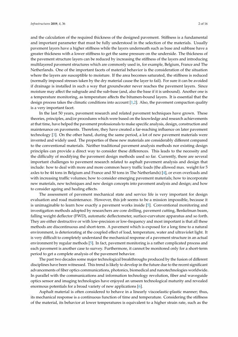
FWD is by now one of the most common non-destructive testing methods to assess bearingcapacity on major road infrastructures by using deflection data generated from a loading device toquantify the response of a pavement structure to known load drops [27,28]. This non-destructivetechnique allows measuring the deflection response of the pavement at several positions under a givenload (Figure 1). The surface deflections obtained from FWD testing are used to back-calculate in situmaterial properties using software which has been developed in the eighties [29]. These properties areconsidered representative for the pavement response to a load and can be used to assess stresses andstrains that are valid for pavement structural and fatigue analysis and design. However, the accuracyof the results (stresses and strains at critical locations in the pavement) depends upon the assumptionsused for the analysis [30].
Infrastructures 2019, 4, x FOR PEER REVIEW 4 of 16
the application of FOS to determine tensile strain at the bottom of an asphalt layer is given in Section 4.
2. Testing Methods and Technologies
This part of the review describes the standardized FWD methodology and several cases of application of FOS in asphalt pavement as an alternative method to FWD to determine tensile strains at the bottom of the asphalt layer.
2.1. Falling Weight Deflectometer
FWD is by now one of the most common non-destructive testing methods to assess bearing capacity on major road infrastructures by using deflection data generated from a loading device to quantify the response of a pavement structure to known load drops [27,28]. This non-destructive technique allows measuring the deflection response of the pavement at several positions under a given load (Figure 1). The surface deflections obtained from FWD testing are used to back-calculate in situ material properties using software which has been developed in the eighties [29]. These properties are considered representative for the pavement response to a load and can be used to assess stresses and strains that are valid for pavement structural and fatigue analysis and design. However, the accuracy of the results (stresses and strains at critical locations in the pavement) depends upon the assumptions used for the analysis [30].
Figure 1. Schematics of the falling weight deflectometer (FWD) test (figure is reproduced from Bilodeau & Doré [31]).
2.2. Fiber Optics Sensors
Pavement monitoring is an essential part of pavement research and plays an important role in pavement management systems [32]. It is known that it is very hard to devise an efficient method to determine realistic mechanical properties of the asphalt pavement. Several gauges were developed to instrument the pavement for its monitoring but considering their high sensitivity to a lot of parameters, not many succeeded to obtain real-time strain data [33] as an alternative method for traditional FWD. FOS gained popularity in the last two decades when an attempt was made to instrument FOS inside the pavement for monitoring purposes. FOS is not commonly used in asphalt technology due to its application restrictions during rough construction processes, which require the sensors to endure high temperatures, moisture, high compaction force, repeated heavy loading and so forth. The accurate measurement of the pavement responses (strain and stress) distributions in pavement structure, combined with temperature, is critical for the understanding of pavement
Figure 1. Schematics of the falling weight deflectometer (FWD) test (figure is reproduced from Bilodeau& Doré [31]).
2.2. Fiber Optics Sensors
Pavement monitoring is an essential part of pavement research and plays an important role inpavement management systems [32]. It is known that it is very hard to devise an efficient method todetermine realistic mechanical properties of the asphalt pavement. Several gauges were developed toinstrument the pavement for its monitoring but considering their high sensitivity to a lot of parameters,not many succeeded to obtain real-time strain data [33] as an alternative method for traditionalFWD. FOS gained popularity in the last two decades when an attempt was made to instrument FOSinside the pavement for monitoring purposes. FOS is not commonly used in asphalt technology
Infrastructures 2019, 4, 36 5 of 16
due to its application restrictions during rough construction processes, which require the sensors toendure high temperatures, moisture, high compaction force, repeated heavy loading and so forth.The accurate measurement of the pavement responses (strain and stress) distributions in pavementstructure, combined with temperature, is critical for the understanding of pavement behavior and themodeling of pavement failure [32]. It was noted by Papavasiliou & Loizos [28] that implementing aFOS system is a time consuming and delicate procedure but it has proved to be a useful and promisingtool for in-situ strain measurements under real traffic loading; however, due to the deviations betweencalculated strains (pavement design, FWD data analysis) and FOS signal records (measured strains)more experimental work was needed.
Below several cases of application of FOS in asphalt pavements are discussed in further detail.
2.2.1. Fiber-Optic Strain Gauge (2007) (Laval University, Canada)
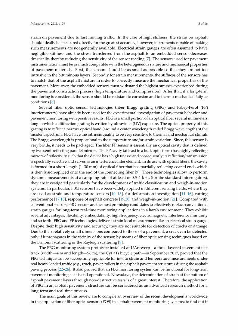
The proposed gauge/instrumented core relates to horizontal strain measurements at the bottomof bound surfacing layers of pavements [34,35]. The gauge is designed to be retrofitted in existingpavement surfacing layers (asphalt concrete, Portland cement concrete or other bound material)through a small diameter core hole to minimize perturbation to the pavement layer to be instrumented.Fiber optic strain sensors are imbedded in the polymeric proof body. Even though electric strain gaugescan be used for the proposed application, fiber optic sensors are preferred due to their insensitivity towater, frost action and electric fields. Figure 2 shows the schematic design of OpSens interferometricfiber optic strain transducer.
Infrastructures 2019, 4, x FOR PEER REVIEW 5 of 16
behavior and the modeling of pavement failure [32]. It was noted by Papavasiliou & Loizos [28] that implementing a FOS system is a time consuming and delicate procedure but it has proved to be a useful and promising tool for in-situ strain measurements under real traffic loading; however, due to the deviations between calculated strains (pavement design, FWD data analysis) and FOS signal records (measured strains) more experimental work was needed.
Below several cases of application of FOS in asphalt pavements are discussed in further detail.
2.2.1. Fiber-Optic Strain Gauge (2007) (Laval University, Canada)
The proposed gauge/instrumented core relates to horizontal strain measurements at the bottom of bound surfacing layers of pavements [34,35]. The gauge is designed to be retrofitted in existing pavement surfacing layers (asphalt concrete, Portland cement concrete or other bound material) through a small diameter core hole to minimize perturbation to the pavement layer to be instrumented. Fiber optic strain sensors are imbedded in the polymeric proof body. Even though electric strain gauges can be used for the proposed application, fiber optic sensors are preferred due to their insensitivity to water, frost action and electric fields. Figure 2 shows the schematic design of OpSens interferometric fiber optic strain transducer.
Figure 2. Strain sensor based on the Fabry-Perot (FP) interferometer (figure is reproduced from OpSens Solutions [36]).
The sensor is made of two optical fibers that are precisely aligned inside a microcapillary tube to form an optical FP sensing interferometer. This makes the strain gauge completely immune to any electromagnetic interference and completely insensitive to transverse strains and temperature, as opposed to fiber optic Bragg gratings sensors.
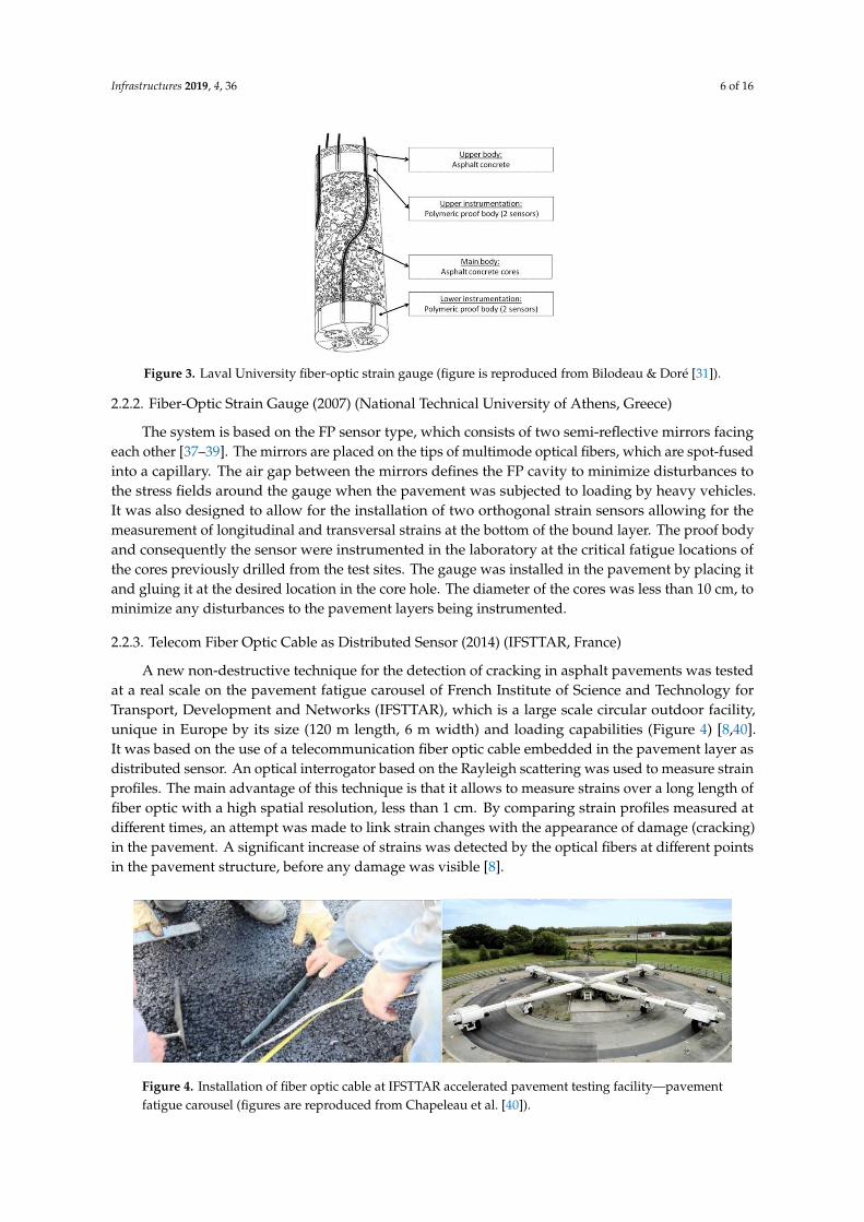
Figure 3. Laval University fiber-optic strain gauge (figure is reproduced from Bilodeau & Doré [31]).
Figure 3 shows a schematic illustration of an instrumented core which includes two measurement levels. Inside each polymeric proof body, two orthogonal fiber optic sensors are
Figure 2. Strain sensor based on the Fabry-Perot (FP) interferometer (figure is reproduced from OpSensSolutions [36]).
The sensor is made of two optical fibers that are precisely aligned inside a microcapillary tubeto form an optical FP sensing interferometer. This makes the strain gauge completely immune toany electromagnetic interference and completely insensitive to transverse strains and temperature, asopposed to fiber optic Bragg gratings sensors.
Figure 3 shows a schematic illustration of an instrumented core which includes two measurementlevels. Inside each polymeric proof body, two orthogonal fiber optic sensors are inserted (dash lines) formeasuring the strain along the longitudinal and the transverse directions of the road. The polymericproof body is made of a plastic composite having an elastic modulus and a thermal coefficient ofcontraction like asphalt concrete, allowing both materials to be mechanically compatible. The materialis sufficiently robust to protect the gauge when the core is subjected to heavy traffic loads and severeclimatic conditions.
Infrastructures 2019, 4, 36 6 of 16
Infrastructures 2019, 4, x FOR PEER REVIEW 5 of 16
behavior and the modeling of pavement failure [32]. It was noted by Papavasiliou & Loizos [28] that implementing a FOS system is a time consuming and delicate procedure but it has proved to be a useful and promising tool for in-situ strain measurements under real traffic loading; however, due to the deviations between calculated strains (pavement design, FWD data analysis) and FOS signal records (measured strains) more experimental work was needed.
Below several cases of application of FOS in asphalt pavements are discussed in further detail.
2.2.1. Fiber-Optic Strain Gauge (2007) (Laval University, Canada)
The proposed gauge/instrumented core relates to horizontal strain measurements at the bottom of bound surfacing layers of pavements [34,35]. The gauge is designed to be retrofitted in existing pavement surfacing layers (asphalt concrete, Portland cement concrete or other bound material) through a small diameter core hole to minimize perturbation to the pavement layer to be instrumented. Fiber optic strain sensors are imbedded in the polymeric proof body. Even though electric strain gauges can be used for the proposed application, fiber optic sensors are preferred due to their insensitivity to water, frost action and electric fields. Figure 2 shows the schematic design of OpSens interferometric fiber optic strain transducer.
Figure 2. Strain sensor based on the Fabry-Perot (FP) interferometer (figure is reproduced from OpSens Solutions [36]).
The sensor is made of two optical fibers that are precisely aligned inside a microcapillary tube to form an optical FP sensing interferometer. This makes the strain gauge completely immune to any electromagnetic interference and completely insensitive to transverse strains and temperature, as opposed to fiber optic Bragg gratings sensors.
Figure 3. Laval University fiber-optic strain gauge (figure is reproduced from Bilodeau & Doré [31]).
Figure 3 shows a schematic illustration of an instrumented core which includes two measurement levels. Inside each polymeric proof body, two orthogonal fiber optic sensors are
Figure 3. Laval University fiber-optic strain gauge (figure is reproduced from Bilodeau & Doré [31]).
2.2.2. Fiber-Optic Strain Gauge (2007) (National Technical University of Athens, Greece)
The system is based on the FP sensor type, which consists of two semi-reflective mirrors facingeach other [37–39]. The mirrors are placed on the tips of multimode optical fibers, which are spot-fusedinto a capillary. The air gap between the mirrors defines the FP cavity to minimize disturbances tothe stress fields around the gauge when the pavement was subjected to loading by heavy vehicles.It was also designed to allow for the installation of two orthogonal strain sensors allowing for themeasurement of longitudinal and transversal strains at the bottom of the bound layer. The proof bodyand consequently the sensor were instrumented in the laboratory at the critical fatigue locations ofthe cores previously drilled from the test sites. The gauge was installed in the pavement by placing itand gluing it at the desired location in the core hole. The diameter of the cores was less than 10 cm, tominimize any disturbances to the pavement layers being instrumented.
2.2.3. Telecom Fiber Optic Cable as Distributed Sensor (2014) (IFSTTAR, France)
A new non-destructive technique for the detection of cracking in asphalt pavements was testedat a real scale on the pavement fatigue carousel of French Institute of Science and Technology forTransport, Development and Networks (IFSTTAR), which is a large scale circular outdoor facility,unique in Europe by its size (120 m length, 6 m width) and loading capabilities (Figure 4) [8,40].It was based on the use of a telecommunication fiber optic cable embedded in the pavement layer asdistributed sensor. An optical interrogator based on the Rayleigh scattering was used to measure strainprofiles. The main advantage of this technique is that it allows to measure strains over a long length offiber optic with a high spatial resolution, less than 1 cm. By comparing strain profiles measured atdifferent times, an attempt was made to link strain changes with the appearance of damage (cracking)in the pavement. A significant increase of strains was detected by the optical fibers at different pointsin the pavement structure, before any damage was visible [8].
Infrastructures 2019, 4, x FOR PEER REVIEW 6 of 16
inserted (dash lines) for measuring the strain along the longitudinal and the transverse directions of the road. The polymeric proof body is made of a plastic composite having an elastic modulus and a thermal coefficient of contraction like asphalt concrete, allowing both materials to be mechanically compatible. The material is sufficiently robust to protect the gauge when the core is subjected to heavy traffic loads and severe climatic conditions.
2.2.2. Fiber-Optic Strain Gauge (2007) (National Technical University of Athens, Greece)
The system is based on the FP sensor type, which consists of two semi-reflective mirrors facing each other [37–39]. The mirrors are placed on the tips of multimode optical fibers, which are spot-fused into a capillary. The air gap between the mirrors defines the FP cavity to minimize disturbances to the stress fields around the gauge when the pavement was subjected to loading by heavy vehicles. It was also designed to allow for the installation of two orthogonal strain sensors allowing for the measurement of longitudinal and transversal strains at the bottom of the bound layer. The proof body and consequently the sensor were instrumented in the laboratory at the critical fatigue locations of the cores previously drilled from the test sites. The gauge was installed in the pavement by placing it and gluing it at the desired location in the core hole. The diameter of the cores was less than 10 cm, to minimize any disturbances to the pavement layers being instrumented.
2.2.3. Telecom Fiber Optic Cable as Distributed Sensor (2014) (IFSTTAR, France)
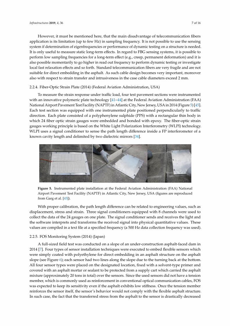
A new non-destructive technique for the detection of cracking in asphalt pavements was tested at a real scale on the pavement fatigue carousel of French Institute of Science and Technology for Transport, Development and Networks (IFSTTAR), which is a large scale circular outdoor facility, unique in Europe by its size (120 m length, 6 m width) and loading capabilities (Figure 4) [8,40]. It was based on the use of a telecommunication fiber optic cable embedded in the pavement layer as distributed sensor. An optical interrogator based on the Rayleigh scattering was used to measure strain profiles. The main advantage of this technique is that it allows to measure strains over a long length of fiber optic with a high spatial resolution, less than 1 cm. By comparing strain profiles measured at different times, an attempt was made to link strain changes with the appearance of damage (cracking) in the pavement. A significant increase of strains was detected by the optical fibers at different points in the pavement structure, before any damage was visible [8].
Figure 4. Installation of fiber optic cable at IFSTTAR accelerated pavement testing facility—pavement fatigue carousel (figures are reproduced from Chapeleau et al. [40]).
However, it must be mentioned here, that the main disadvantage of telecommunication fibers application is its limitation (up to few Hz) in sampling frequency. It is not possible to use the sensing system if determination of eigenfrequencies or performance of dynamic testing on a structure is needed. It is only useful to measure static long-term effects. In regard to FBG sensing systems, it is possible to perform low sampling frequencies for a long-term effect (e.g., creep, permanent deformation) and it is also possible momentarily to go higher in read out frequency to perform dynamic testing or investigate local fast relaxation effects and so forth. Standard telecommunication fibers are very fragile and are not suitable for direct embedding in the asphalt. As such cable design
Figure 4. Installation of fiber optic cable at IFSTTAR accelerated pavement testing facility—pavementfatigue carousel (figures are reproduced from Chapeleau et al. [40]).
Infrastructures 2019, 4, 36 7 of 16
However, it must be mentioned here, that the main disadvantage of telecommunication fibersapplication is its limitation (up to few Hz) in sampling frequency. It is not possible to use the sensingsystem if determination of eigenfrequencies or performance of dynamic testing on a structure is needed.It is only useful to measure static long-term effects. In regard to FBG sensing systems, it is possible toperform low sampling frequencies for a long-term effect (e.g., creep, permanent deformation) and it isalso possible momentarily to go higher in read out frequency to perform dynamic testing or investigatelocal fast relaxation effects and so forth. Standard telecommunication fibers are very fragile and are notsuitable for direct embedding in the asphalt. As such cable design becomes very important, moreoveralso with respect to strain transfer and intrusiveness in the case cable diameters exceed 2 mm.
2.2.4. Fiber-Optic Strain Plate (2014) (Federal Aviation Administration, USA)
To measure the strain response under traffic load, four test pavement sections were instrumentedwith an innovative polymeric plate technology [41–44] at the Federal Aviation Administration (FAA)National Airport Pavement Test Facility (NAPTF) in Atlantic City, New Jersey, USA in 2014 (Figure 5) [45].Each test section was equipped with one instrumented plate positioned perpendicularly to trafficdirection. Each plate consisted of a polyphenylene sulphide (PPS) with a rectangular thin body inwhich 24 fiber optic strain gauges were embedded and bonded with epoxy. The fiber-optic straingauges working principle is based on the White Light Polarization Interferometry (WLPI) technology.WLPI uses a signal conditioner to sense the path length difference inside a FP interferometer of aknown cavity length and delimited by two dielectric mirrors [34].
Infrastructures 2019, 4, x FOR PEER REVIEW 7 of 16
becomes very important, moreover also with respect to strain transfer and intrusiveness in the case cable diameters exceed 2 mm.
2.2.4. Fiber-Optic Strain Plate (2014) (Federal Aviation Administration, USA)
To measure the strain response under traffic load, four test pavement sections were instrumented with an innovative polymeric plate technology [41–44] at the Federal Aviation Administration (FAA) National Airport Pavement Test Facility (NAPTF) in Atlantic City, New Jersey, USA in 2014 (Figure 5) [45]. Each test section was equipped with one instrumented plate positioned perpendicularly to traffic direction. Each plate consisted of a polyphenylene sulphide (PPS) with a rectangular thin body in which 24 fiber optic strain gauges were embedded and bonded with epoxy. The fiber-optic strain gauges working principle is based on the White Light Polarization Interferometry (WLPI) technology. WLPI uses a signal conditioner to sense the path length difference inside a FP interferometer of a known cavity length and delimited by two dielectric mirrors [34].
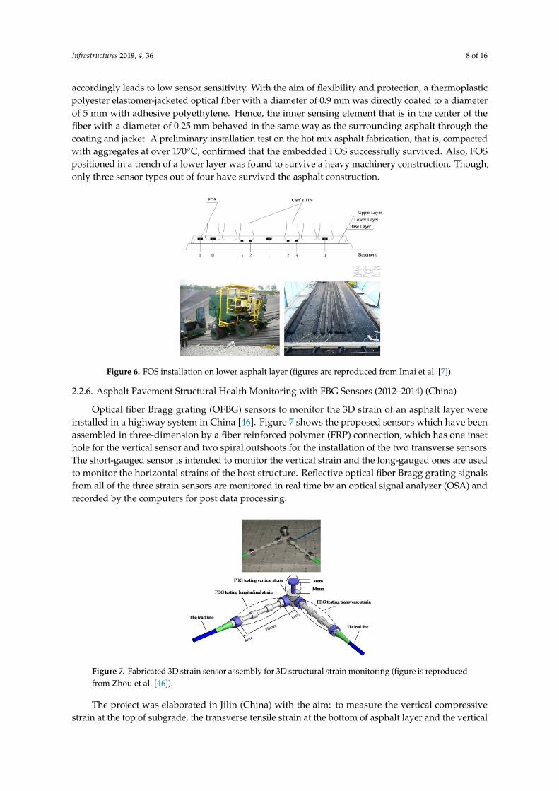
Figure 5. Instrumented plate installation at the Federal Aviation Administration (FAA) National Airport Pavement Test Facility (NAPTF) in Atlantic City, New Jersey, USA (figures are reproduced from Garg et al. [45]).
With proper calibration, the path length difference can be related to engineering values, such as displacement, stress and strain. Three signal conditioners equipped with 8 channels were used to collect the data of the 24 gauges on one plate. The signal conditioner sends and receives the light and the software interprets and transforms the received signal into physical quantitative values. These values are compiled in a text file at a specified frequency (a 500 Hz data collection frequency was used).
2.2.5. FOS Monitoring System (2014) (Japan)
A full-sized field test was conducted on a slope of an under-construction asphalt-faced dam in 2014 [7]. Four types of sensor installation techniques were executed to embed flexible sensors which were simply coated with polyethylene for direct embedding in an asphalt structure on the asphalt slope (see Figure 6); each sensor had two lines along the slope due to the turning back at the bottom. All four sensor types were placed on the designated location, fixed with a solvent-type primer and covered with an asphalt mortar or sealant to be protected from a supply cart which carried the asphalt mixture (approximately 20 tons in total) over the sensors. Since the used sensors did not have a tension member, which is commonly used as reinforcement in conventional optical communication cables, FOS was expected to keep its sensitivity even if the asphalt exhibits low stiffness. Once the tension member reinforces the sensor itself, the sensor’s behavior would not comply with the flexible asphalt structure. In such case, the fact that the transferred stress from the asphalt to the sensor is drastically decreased accordingly leads to low sensor sensitivity. With the aim of flexibility and protection, a thermoplastic polyester elastomer-jacketed optical fiber with a diameter of 0.9 mm was directly coated to a diameter of 5 mm with adhesive polyethylene. Hence, the inner sensing element that is in the center of the fiber with a diameter of 0.25 mm behaved in the same way as the surrounding asphalt through the coating and jacket. A preliminary installation test on the hot mix asphalt fabrication, that is, compacted with aggregates at over 170°C, confirmed that the embedded
Figure 5. Instrumented plate installation at the Federal Aviation Administration (FAA) NationalAirport Pavement Test Facility (NAPTF) in Atlantic City, New Jersey, USA (figures are reproducedfrom Garg et al. [45]).
With proper calibration, the path length difference can be related to engineering values, such asdisplacement, stress and strain. Three signal conditioners equipped with 8 channels were used tocollect the data of the 24 gauges on one plate. The signal conditioner sends and receives the light andthe software interprets and transforms the received signal into physical quantitative values. Thesevalues are compiled in a text file at a specified frequency (a 500 Hz data collection frequency was used).
2.2.5. FOS Monitoring System (2014) (Japan)
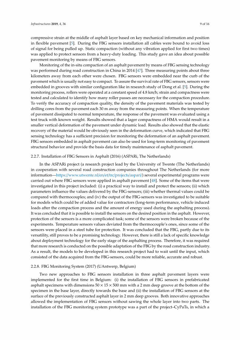
A full-sized field test was conducted on a slope of an under-construction asphalt-faced dam in2014 [7]. Four types of sensor installation techniques were executed to embed flexible sensors whichwere simply coated with polyethylene for direct embedding in an asphalt structure on the asphaltslope (see Figure 6); each sensor had two lines along the slope due to the turning back at the bottom.All four sensor types were placed on the designated location, fixed with a solvent-type primer andcovered with an asphalt mortar or sealant to be protected from a supply cart which carried the asphaltmixture (approximately 20 tons in total) over the sensors. Since the used sensors did not have a tensionmember, which is commonly used as reinforcement in conventional optical communication cables, FOSwas expected to keep its sensitivity even if the asphalt exhibits low stiffness. Once the tension memberreinforces the sensor itself, the sensor’s behavior would not comply with the flexible asphalt structure.In such case, the fact that the transferred stress from the asphalt to the sensor is drastically decreased
Infrastructures 2019, 4, 36 8 of 16
accordingly leads to low sensor sensitivity. With the aim of flexibility and protection, a thermoplasticpolyester elastomer-jacketed optical fiber with a diameter of 0.9 mm was directly coated to a diameterof 5 mm with adhesive polyethylene. Hence, the inner sensing element that is in the center of thefiber with a diameter of 0.25 mm behaved in the same way as the surrounding asphalt through thecoating and jacket. A preliminary installation test on the hot mix asphalt fabrication, that is, compactedwith aggregates at over 170◦C, confirmed that the embedded FOS successfully survived. Also, FOSpositioned in a trench of a lower layer was found to survive a heavy machinery construction. Though,only three sensor types out of four have survived the asphalt construction.
Infrastructures 2019, 4, x FOR PEER REVIEW 8 of 16
FOS successfully survived. Also, FOS positioned in a trench of a lower layer was found to survive a heavy machinery construction. Though, only three sensor types out of four have survived the asphalt construction.
Figure 6. FOS installation on lower asphalt layer (figures are reproduced from Imai et al. [7]).
2.2.6. Asphalt Pavement Structural Health Monitoring with FBG Sensors (2012–2014) (China)
Optical fiber Bragg grating (OFBG) sensors to monitor the 3D strain of an asphalt layer were installed in a highway system in China [46]. Figure 7 shows the proposed sensors which have been assembled in three-dimension by a fiber reinforced polymer (FRP) connection, which has one inset hole for the vertical sensor and two spiral outshoots for the installation of the two transverse sensors. The short-gauged sensor is intended to monitor the vertical strain and the long-gauged ones are used to monitor the horizontal strains of the host structure. Reflective optical fiber Bragg grating signals from all of the three strain sensors are monitored in real time by an optical signal analyzer (OSA) and recorded by the computers for post data processing.
The project was elaborated in Jilin (China) with the aim: to measure the vertical compressive strain at the top of subgrade, the transverse tensile strain at the bottom of asphalt layer and the vertical compressive strain at the middle of asphalt layer based on key mechanical information and position in flexible pavement [5]. During the FBG sensors installation all cables were bound to avoid loss of signal for being pulled up. Static compaction (without any vibration applied for first two times) was applied to protect sensors from a heavy-duty loading. This study gave an idea about possible pavement monitoring by means of FBG sensors.
Figure 7. Fabricated 3D strain sensor assembly for 3D structural strain monitoring (figure is reproduced from Zhou et al. [46]).
Figure 6. FOS installation on lower asphalt layer (figures are reproduced from Imai et al. [7]).
2.2.6. Asphalt Pavement Structural Health Monitoring with FBG Sensors (2012–2014) (China)
Optical fiber Bragg grating (OFBG) sensors to monitor the 3D strain of an asphalt layer wereinstalled in a highway system in China [46]. Figure 7 shows the proposed sensors which have beenassembled in three-dimension by a fiber reinforced polymer (FRP) connection, which has one insethole for the vertical sensor and two spiral outshoots for the installation of the two transverse sensors.The short-gauged sensor is intended to monitor the vertical strain and the long-gauged ones are usedto monitor the horizontal strains of the host structure. Reflective optical fiber Bragg grating signalsfrom all of the three strain sensors are monitored in real time by an optical signal analyzer (OSA) andrecorded by the computers for post data processing.
Infrastructures 2019, 4, x FOR PEER REVIEW 8 of 16
FOS successfully survived. Also, FOS positioned in a trench of a lower layer was found to survive a heavy machinery construction. Though, only three sensor types out of four have survived the asphalt construction.
Figure 6. FOS installation on lower asphalt layer (figures are reproduced from Imai et al. [7]).
2.2.6. Asphalt Pavement Structural Health Monitoring with FBG Sensors (2012–2014) (China)
Optical fiber Bragg grating (OFBG) sensors to monitor the 3D strain of an asphalt layer were installed in a highway system in China [46]. Figure 7 shows the proposed sensors which have been assembled in three-dimension by a fiber reinforced polymer (FRP) connection, which has one inset hole for the vertical sensor and two spiral outshoots for the installation of the two transverse sensors. The short-gauged sensor is intended to monitor the vertical strain and the long-gauged ones are used to monitor the horizontal strains of the host structure. Reflective optical fiber Bragg grating signals from all of the three strain sensors are monitored in real time by an optical signal analyzer (OSA) and recorded by the computers for post data processing.
The project was elaborated in Jilin (China) with the aim: to measure the vertical compressive strain at the top of subgrade, the transverse tensile strain at the bottom of asphalt layer and the vertical compressive strain at the middle of asphalt layer based on key mechanical information and position in flexible pavement [5]. During the FBG sensors installation all cables were bound to avoid loss of signal for being pulled up. Static compaction (without any vibration applied for first two times) was applied to protect sensors from a heavy-duty loading. This study gave an idea about possible pavement monitoring by means of FBG sensors.
Figure 7. Fabricated 3D strain sensor assembly for 3D structural strain monitoring (figure is reproduced from Zhou et al. [46]).
Figure 7. Fabricated 3D strain sensor assembly for 3D structural strain monitoring (figure is reproducedfrom Zhou et al. [46]).
The project was elaborated in Jilin (China) with the aim: to measure the vertical compressivestrain at the top of subgrade, the transverse tensile strain at the bottom of asphalt layer and the vertical
Infrastructures 2019, 4, 36 9 of 16
compressive strain at the middle of asphalt layer based on key mechanical information and positionin flexible pavement [5]. During the FBG sensors installation all cables were bound to avoid lossof signal for being pulled up. Static compaction (without any vibration applied for first two times)was applied to protect sensors from a heavy-duty loading. This study gave an idea about possiblepavement monitoring by means of FBG sensors.
Monitoring of the in-situ compaction of an asphalt pavement by means of FBG sensing technologywas performed during road construction in China in 2014 [47]. Three measuring points about threekilometers away from each other were chosen. FBG sensors were embedded near the curb of thepavement which is usually not easy to compact. To assure the survival rate of FBG sensors, sensors wereembedded in grooves with similar configuration like in research study of Dong et al. [5]. During themonitoring process, rollers were operated at a constant speed of 4.8 km/h; strain and compactness weretested and calculated to identify how many roller passes are necessary for the compaction procedure.To verify the accuracy of compaction quality, the density of the pavement materials was tested bydrilling cores from the pavement each 30 m away from the measuring points. When the temperatureof pavement dissipated to normal temperature, the response of the pavement was evaluated using atest truck with known weight. Results showed that a lager compactness of HMA would result in asmaller vertical deformation of the pavement under dynamic load. Results also showed that the elasticrecovery of the material would be obviously seen in the deformation curve, which indicated that FBGsensing technology has a sufficient precision for monitoring the deformation of an asphalt pavement.FBG sensors embedded in asphalt pavement can also be used for long-term monitoring of pavementstructural behavior and provide the basis data for timely maintenance of asphalt pavement.
2.2.7. Installation of FBG Sensors in Asphalt (2016) (ASPARi, The Netherlands)
In the ASPARi project (a research project lead by the University of Twente (The Netherlands)in cooperation with several road construction companies throughout The Netherlands (for moreinformation—https://www.utwente.nl/en/et/trc/projects/aspari/) several experimental programs werecarried out where FBG sensors were applied in asphalt pavement [48]. Some of the items that wereinvestigated in this project included: (i) a practical way to install and protect the sensors; (ii) whichparameters influence the values delivered by the FBG-sensors; (iii) whether thermal values could becompared with thermocouples; and (iv) the output of the FBG-sensors was investigated to be suitablefor models which could be of added value for contractors (long-term performance, vehicle inducedloads after the compaction process and the amount of energy used during the asphalting process).It was concluded that it is possible to install the sensors on the desired position in the asphalt. However,protection of the sensors is a more complicated task; some of the sensors were broken because of theexperiments. Temperature sensors values deviated from the thermocouple’s ones, since some of thesensors were placed in a steel tube for protection. It was concluded that the FBG, partly due to itsversatility, still proves to be a promising technology. However, there is still a lack of specific knowledgeabout deployment technology for the early stage of the asphalting process. Therefore, it was requiredthat more research is conducted on the possible adaptation of the FBG by the road construction industry.As a result, the models to be developed in this research project had to wait until the input, whichconsisted of the data acquired from the FBG-sensors, could be more reliable, accurate and robust.
2.2.8. FBG Monitoring System (2017) (UAntwerp, Belgium)
Two new approaches to FBG sensors installation in three asphalt pavement layers wereimplemented for the first time in Belgium: (i) the installation of FBG sensors in prefabricatedasphalt specimens with dimensions 50 × 15 × 500 mm with a 2 mm deep groove at the bottom of thespecimen in the base layer, directly towards the base and (ii) the installation of FBG sensors at thesurface of the previously constructed asphalt layer in 2 mm deep grooves. Both innovative approachesallowed the implementation of FBG sensors without sawing the whole layer into two parts. Theinstallation of the FBG monitoring system prototype was a part of the project–CyPaTs, in which a
Infrastructures 2019, 4, 36 10 of 16
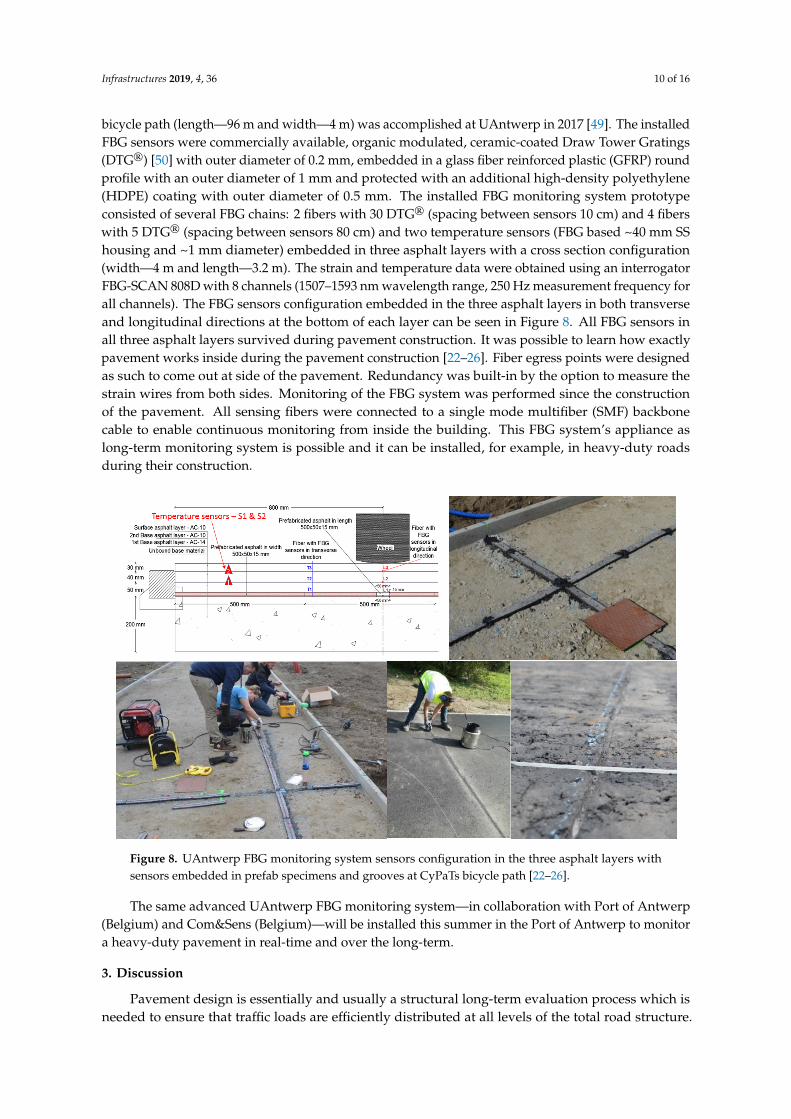
bicycle path (length—96 m and width—4 m) was accomplished at UAntwerp in 2017 [49]. The installedFBG sensors were commercially available, organic modulated, ceramic-coated Draw Tower Gratings(DTG®) [50] with outer diameter of 0.2 mm, embedded in a glass fiber reinforced plastic (GFRP) roundprofile with an outer diameter of 1 mm and protected with an additional high-density polyethylene(HDPE) coating with outer diameter of 0.5 mm. The installed FBG monitoring system prototypeconsisted of several FBG chains: 2 fibers with 30 DTG® (spacing between sensors 10 cm) and 4 fiberswith 5 DTG® (spacing between sensors 80 cm) and two temperature sensors (FBG based ~40 mm SShousing and ~1 mm diameter) embedded in three asphalt layers with a cross section configuration(width—4 m and length—3.2 m). The strain and temperature data were obtained using an interrogatorFBG-SCAN 808D with 8 channels (1507–1593 nm wavelength range, 250 Hz measurement frequency forall channels). The FBG sensors configuration embedded in the three asphalt layers in both transverseand longitudinal directions at the bottom of each layer can be seen in Figure 8. All FBG sensors inall three asphalt layers survived during pavement construction. It was possible to learn how exactlypavement works inside during the pavement construction [22–26]. Fiber egress points were designedas such to come out at side of the pavement. Redundancy was built-in by the option to measure thestrain wires from both sides. Monitoring of the FBG system was performed since the constructionof the pavement. All sensing fibers were connected to a single mode multifiber (SMF) backbonecable to enable continuous monitoring from inside the building. This FBG system’s appliance aslong-term monitoring system is possible and it can be installed, for example, in heavy-duty roadsduring their construction.
Infrastructures 2019, 4, x FOR PEER REVIEW 10 of 16
consisted of several FBG chains: 2 fibers with 30 DTG® (spacing between sensors 10 cm) and 4 fibers with 5 DTG® (spacing between sensors 80 cm) and two temperature sensors (FBG based ~40 mm SS housing and ~1 mm diameter) embedded in three asphalt layers with a cross section configuration (width—4 m and length—3.2 m). The strain and temperature data were obtained using an interrogator FBG-SCAN 808D with 8 channels (1507–1593 nm wavelength range, 250 Hz measurement frequency for all channels). The FBG sensors configuration embedded in the three asphalt layers in both transverse and longitudinal directions at the bottom of each layer can be seen in Figure 8. All FBG sensors in all three asphalt layers survived during pavement construction. It was possible to learn how exactly pavement works inside during the pavement construction [22–26]. Fiber egress points were designed as such to come out at side of the pavement. Redundancy was built-in by the option to measure the strain wires from both sides. Monitoring of the FBG system was performed since the construction of the pavement. All sensing fibers were connected to a single mode multifiber (SMF) backbone cable to enable continuous monitoring from inside the building. This FBG system’s appliance as long-term monitoring system is possible and it can be installed, for example, in heavy-duty roads during their construction.
The same advanced UAntwerp FBG monitoring system—in collaboration with Port of Antwerp (Belgium) and Com&Sens (Belgium)—will be installed this summer in the Port of Antwerp to monitor a heavy-duty pavement in real-time and over the long-term.
Figure 8. UAntwerp FBG monitoring system sensors configuration in the three asphalt layers with sensors embedded in prefab specimens and grooves at CyPaTs bicycle path [22–26].
3. Discussion
Pavement design is essentially and usually a structural long-term evaluation process which is needed to ensure that traffic loads are efficiently distributed at all levels of the total road structure. Furthermore, it cannot be monitored only for a short-term period to get a complete analysis of the pavement behavior. As shown in the selected literature, FBG sensors are the most promising candidates to effectively replace conventional strain gauges for a long-term monitoring application in a harsh environment.
This part of the review describes the outcome of the results if those systems provide repeatable and suitable results for a long-term monitoring and of the inverse modeling approach performed by several researchers from the above-mentioned research studies using FOS, strain gauges and FWD. It must be noted that only few studies made the comparison between the FOS strain results and the
Figure 8. UAntwerp FBG monitoring system sensors configuration in the three asphalt layers withsensors embedded in prefab specimens and grooves at CyPaTs bicycle path [22–26].
The same advanced UAntwerp FBG monitoring system—in collaboration with Port of Antwerp(Belgium) and Com&Sens (Belgium)—will be installed this summer in the Port of Antwerp to monitora heavy-duty pavement in real-time and over the long-term.
3. Discussion
Pavement design is essentially and usually a structural long-term evaluation process which isneeded to ensure that traffic loads are efficiently distributed at all levels of the total road structure.
Infrastructures 2019, 4, 36 11 of 16
Furthermore, it cannot be monitored only for a short-term period to get a complete analysis ofthe pavement behavior. As shown in the selected literature, FBG sensors are the most promisingcandidates to effectively replace conventional strain gauges for a long-term monitoring application ina harsh environment.
This part of the review describes the outcome of the results if those systems provide repeatableand suitable results for a long-term monitoring and of the inverse modeling approach performed byseveral researchers from the above-mentioned research studies using FOS, strain gauges and FWD.It must be noted that only few studies made the comparison between the FOS strain results andthe FWD measurements. Most of the studies were focused on the feasibility of applying FOS inpavement structures.
In the research group of NTUA, Greece [39] a FOS system was used for horizontal (tensile) strainmeasurements at the top and the bottom of a foamed asphalt (FA) layer. These locations were selected,considering the results of the strain response analysis based on back-calculated moduli at characteristiclocations within the body of the recycled layer in a similar pavement structure. Tensile strains at theselocations were critical in terms of possible fatigue failure and directly related to the performance of thepavement structure. Strain measurements were conducted with the FOS system during FWD loading(40 kN). In-depth temperature measurements were conducted with thermometers into drilled holesand using a single drop of glycerol, according to COST 336. Back-calculation of the recycled pavementlayer moduli was carried out using MODCOMP© software (US). The horizontal (tensile) strains at thetop as well as at the bottom of the foamed asphalt layer were calculated using finite-element linearanalysis (FEA), using the ABAQUS© software (US). Compared to a much simpler multilayer elasticsystem analysis, the three-dimensional (3D) FEA was considered as more precise for the simulation ofthe FWD loading. The back-calculated moduli of the pavement’s layers were used as input for theforward FEA. Because the target of the analysis is the comparison of the calculated strains with themeasured values, no adjustment of the back-calculated foamed asphalt moduli was conducted. Themaximum measured tensile strains at the bottom of the FA layer, transversely or longitudinally, rangedfrom 6 to 15 µε when applying FWD loading of 40 kN. The maximum calculated tensile strains (FEA)ranged from 19 to 34 µε. The maximum measured tensile strains at the top of the foamed asphaltlayer (respectively bottom of the asphalt layers), transversely or longitudinally, ranged from −10 to7 µε when applying an FWD loading of 40 kN. The maximum calculated tensile strains (FEA) rangedfrom 3 to 19 µε. In all cases, the measured strains were lower than the relative calculated strains,indicating that the FEA overestimates the tensile strains, especially at the bottom of the FA layer. Thisdiscrepancy can be attributed to various sources of uncertainty during the calculations. There may alsobe errors and limitations in instrumentation design and installation that contribute to the mentioneddifferences [39]. It can be noted here that the strain measurements could also be underestimated orthat the sensing system itself had influence on the material behavior. It was concluded that FWD canonly be used as excitation to obtain tensile strain values of FA pavement materials by means of FOS.This outcome is promising towards the possibility of potential use of FWD for simulating the straininduced by a moving tire. However, as it was noted by Loizos et al. [39], more in situ data (measuredstrains) could lead to more reliable conclusions.
In the research group of University of Laval, Canada, it was noted by Bilodeau & Doré [31] that anexisting alternative approach for determining the tensile strain occurring at the bottom of the asphaltconcrete layer consists of bypassing the necessity of back-calculating the modulus of each layer bydirect strain estimation from the deflection basin. In most cases, this approach overestimates thetensile strains occurring at the bottom of asphalt/concrete layers, leading to an underestimation ofthe pavement’s fatigue life. A model has been developed based on a theoretical analysis and a fieldcalibration using data obtained at the Laval University experimental pavement site which allowed tocompute tensile strain values that are in good agreement with tensile strain values obtained usingtheoretical models and, also with field measurements. The proposed approach to determine the tensilestrain at the bottom of asphalt concrete layers using the deflection basin is based on Equations (1)–(3)
Infrastructures 2019, 4, 36 12 of 16
to estimate the modulus of the mechanically involved layers, which are the asphalt concrete and baselayers:
εmodelt =
HAC(0.199 + 3.868× 10⁻² log(EAC) − 1.122× 10⁻⁴Ebase − 8.627× 10⁻³HAC
2R(1)
log|E∗| = 0.95 +3.27
1 + e(−2.67−0.51 log f+0.07T)(2)
Ebase = [41.333 ln(EAC) − 438.43][ln(HAC) − 5.9877] + 50.683 (3)
in which HAC is the thickness (mm), EAC is modulus of the asphalt concrete layer (MPa), Ebase isthe modulus of the aggregate base layer (MPa), |E∗| is the dynamic modulus (MPa), f is the loadingfrequency (Hz) and T is the temperature (◦C). To use the proposed model, the following values have tobe obtained: temperature of the asphalt concrete, loading frequency of the FWD, deflection basin (d0
and d200 in mm), loading plate radius (mm) and thickness of asphalt concrete (mm). Therefore, themodel is based on easily obtainable parameters and has a good prediction capacity. The tensile strainsinduced at the bottom of the asphalt concrete layer were measured with two different fiber optic straingauges (asphalt concrete cores and plate). The FWD drops (40 kN) were applied directly on top ofthe sensors. The temperature was measured using a sensor located inside the asphalt concrete layer.Between the FWD tests, the temperature of the instrumented pavement zone was also controlled witha thermal blanket connected to two thermal baths controlling the circulated fluid temperature. Anaverage loading frequency of 34 Hz was found for the FWD tests. A calibration factor of 1.87 is foundbetween the model and the field conditions. This difference may be attributed to numerous factors, suchas the difference between idealized modelling conditions, which were set for simplification reasonsand non-ideal field conditions. As part of the field validation and calibration process, the objective wasto identify a coefficient such as the one that was presented to consider the main differences between themodel and the field conditions. Equation (1) allows the tensile strain to be determined at the bottom ofthe asphalt concrete layer as determined with finite element modelling using a combination of asphaltconcrete thickness and modulus, base layer modulus, as well as using the deflection basin through theradius of curvature [31].
In the study of Primusz et al. [51], an approach was presented to define the modulus of theexamined pavement layers, knowing the deflection curve and the thickness of the bound layer,without using further back-calculation. According to the performed research, there is a very strongcorrespondence between the E modulus of the bottom layer, the vertical deflection interpreted at theload axis and the radius of curvature of the pavement:
E = 1224.45·D−1.6230 ·R−0.629
0 (4)
where D0 is the measured vertical deflection (mm), R0 is radius of curvature (m).The objective of the study of Grellet et al. [44], as a part of a collaborative project between Laval
University (Quebec City, Canada) and the IFSTTAR (Nantes, France), was to integrate viscoelasticproperties in an asphalt pavement model in order to understand and predict the two types of crackingmechanisms: (i) initiated at the bottom of the asphalt layer and propagating toward the surface(bottom-up cracks); (ii) the second is initiated near the surface of the pavement and propagatesdownward through the bound layers (top-down cracks). The field tests have been conducted at theIFSTTAR’s accelerated pavement testing facility and at the SERUL (Laval University Road ExperimentalSite). Results from these studies showed that fiber optic sensors allowed adequately characterizingthe strains occurring within the layer and evaluating the effects of the load configurations [43]. Itwas concluded in Grellet et al. [44] that a better pavement modeling is obtained using viscoelasticproperties for the mechanical behavior of the asphalt layers and for the interface. Modeling the tackcoat with a viscoelastic layer modifies the stresses and strain distribution through the layers and alters
Infrastructures 2019, 4, 36 13 of 16
the prediction of pavement performance. Significant tensile stresses appear near the surface and couldproduce top-down cracking. The integration of the viscoelastic interface imposes a redistribution ofthe stresses through the layer. Tensile stresses increase near the surface and near the interface butdecrease at the bottom of the layers. However, strains are higher considering the interface. The highextension strains (more than 250 µε) have been measured at the bottom of the bituminous wearingcourse of a thin pavement structure at a high temperature (30◦C) with a slow return of the strains tozero after loading.
The high tensile strains observed at high temperature at the bottom of the wearing course suggestthat at high temperature, the interface with the lower layers cannot be considered as fully bonded andthat some sliding between the wearing course and the base course occurs, generating these tensilestrains. In other words, this means that the degree of bonding of the interface seems to change withtemperature. This could be explained by the behavior of the tack coat (bitumen emulsion) at theinterface; at high temperature, this emulsion presents a low stiffness, which reduces the shear resistanceof the interface [51] It was stated that several temperature and load parameters must be evaluated todetermine the most critical conditions.
An interesting outcome can be found in the study of Duong et al. [52], showing the results of themonitoring by means of strain gauges of an experimental pavement section recently re-constructedon a French motorway. The measurements showed that at high temperatures (above 30◦C), highstrain levels (150 µε) are measured at the bottom of the bituminous layers. These strains exceed thelimit fatigue strain, leading to failure for 1 million load cycles, determined using standard two-pointbending fatigue tests, performed at 10◦C and 25 Hz. Similar tests results had been obtained previouslyat IFSTTAR in accelerated pavement tests. Calculations were performed with the ALIZE-LCPC andViscoroute programs (France), to fit the experimental strains, using elastic and viscoelastic pavementmodels. These calculations have shown that the pavement interfaces cannot be considered as fullybonded and that their level of bonding clearly changes with temperature. Different modelling caseshave been tested and the best predictions have been obtained when modelling the interfaces as thinelastic layers (2 mm thick), with a low elastic modulus (in the range of 120 to 20 MPa for the rangeof low to high temperatures obtained on site). These interface layer moduli decreased when thetemperature increased, and a particularly significant drop was observed between 25◦C and 30◦Cwith both ALIZE-LCPC and Viscoroute calculations. These results stress the fact that in pavementcalculations, great attention should be paid to the modelling of pavement layer interfaces. Theseinterfaces cannot be considered as fully bonded in all cases and in particular, their degree of bondingmay decrease at high temperatures (above 30◦C), where the stiffness of the tack coat at the interfacebecomes very low. This can lead to higher tensile strains at the bottom of the bituminous layers thanpredicted by standard design calculations, with bonded layers and thus to higher fatigue damagethan predicted.
4. Conclusions
The most significant cases/attempts to perform experimental measurements with optical fibersin asphalt pavements in the last two decades have been included in this paper. Some of the mainconclusions can be summarized as follows: the available technical information described mostly theattempts to install the FOS in the pavement; only a few studies provided technical details on the FOSinstallation; only a few cases could be referred to as long-term pavement monitoring; most of the casesenvisaged more experimental measurements than monitoring of the pavement itself. Some suggestedsolutions were given to validate an inverse modelling approach based on the results of FWD and FOS.It can be concluded that the application of FOS in the asphalt pavement: (i) has proved to be a usefuland a promising tool for in-situ strain measurements under real traffic loading at the bottom of theasphalt layers; (ii) it also proved that interfaces of the pavement structure cannot be considered as fullybonded, in particular, at high temperatures, although when using the standardized FWD methodologyit is always considered that interfaces are fully bonded; (iii) instrumentation design and installation
Infrastructures 2019, 4, 36 14 of 16
of FOS contributes to the differences in calculated and measured tensile strain values; (iv) due to thedeviations between calculated strains (pavement design, FWD data analysis) and FOS signal records(measured strains) more experimental work is needed to define a calibration factor.
Author Contributions: Writing—original draft preparation, P.K.D.M.; Writing—editing, G.L., C.V., E.V. andW.V.d.b.; Writing—review, S.V., J.B., N.S. and J.D.W.
Funding: This research was funded by the Port of Antwerp (within the project “Duurzame Asfaltverhardingenvoor zwaar belaste wegdekken”) and by the University Research Fund at the University of Antwerp throughthe project BOF/STIMPRO/36539 “Development of a novel optical signal processing method for analyzing dataof the deformations of the asphalt construction by using Fiber Bragg technology to design new asphalt model,”supported by both the Road Engineering Research Section (EMIB) and Op3Mech research group.
Conflicts of Interest: The authors declare no conflict of interest.
References
1. Read, J.; Whiteoak, D.; Hunter, R.N. The Shell Bitumen Handbook; Thomas Telford: London, UK, 2003; p. 460.2. Van Gurp, C.A.P.M. Characterization of Seasonal Influences on Asphalt Pavements with the Use of Falling Weight
Deflectometers. Ph.D. Thesis, TU Delft, Delft, The Netherland, 1995. Available online: https://repository.tudelft.nl/islandora/object/uuid:596d5b28-308d-4c74-a3b8-cad632a93619?collection=research (accessed on 12 May 2019).
3. Sun, L. Structural Behavior of Asphalt Pavements; Butterworth-Heinemann: Oxford, UK, 2016; p. 1070,ISBN 978-0-1280-2893-3.
4. Permissible Maximum Weights of Lorries in Europe, International Transport Forum. 2015. Available online:https://www.itf-oecd.org/sites/default/files/docs/weights_0.pdf (accessed on 12 May 2019).
5. Dong, Z.; Li, S.; Wen, J.; Chen, H. Asphalt pavement structural health monitoring utilizing FBG sensors.Adv. Eng. Forum 2012, 5, 339–344. [CrossRef]
6. Bock, W.J.; Gannot, I.; Tanev, S. Optical Waveguide Sensing and Imaging, NATO Science for Peace and SecuritySeries-B: Physics and Biophysics; Springer: Dordrecht, The Netherlands, 2008; p. 269. [CrossRef]
7. Imai, M.; Igarashi, Y.; Shibata, M.; Miura, S. Experimental study on strain and deformation monitoring ofasphalt structures using embedded fiber optic sensor. J. Civ. Struct. Health Monit. 2014, 4, 209–220. [CrossRef]
8. Chapeleau, X.; Blanc, J.; Hornych, P.; Gautier, J.-L.; Carroget, J. Assessment of cracks detection in pavementby a distributed fiber optic sensing technology. J. Civ. Struct. Health Monit. 2017, 7, 459–470. [CrossRef]
9. Meggitt, B.T. Chapter 17-Fiber Optics in Sensor Instrumentation. In Instrumentation Reference Book; Boyes, W.,Ed.; Butterworth-Heinemann: Oxford, UK, 2010; pp. 191–216. [CrossRef]
10. Wang, J.-N.; Tang, J.-L.; Chang, H.-P. Fiber Bragg grating sensors for use in pavement structuralstrain-temperature monitoring. Proc. SPIE 2006, 6174, 61743S. [CrossRef]
11. Luyckx, G.; Voet, E.; Lammens, N.; Degrieck, J. Strain measurements of composite laminates with embeddedfibre Bragg gratings: Criticism and opportunities for research. Sensors 2011, 11, 384–408. [CrossRef] [PubMed]
12. Geernaert, T.; Sulejmani, S.; Sonnenfeld, C.; Luyckx, G.; Chah, K.; Areias, L.; Mergo, P.; Urbanczyk, W.; VanMarcke, P.; Coppens, E.; et al. Microstructured optical fiber Bragg grating-based strain and temperaturesensing in the concrete buffer of the Belgian supercontainer concept. Proc. SPIE 2014, 9157, 915777. [CrossRef]
13. Luyckx, G.; Voet, E.; Grefhorst, R.; Peeters, J.; Degrieck, J. Long term monitoring of an all-composite waterlock using fibre optics. In Proceedings of the SAMPE EUROPE 2016, Liege, Belgium, 13–15 September 2016.
14. Liu, W.; Liu, X.; Wang, Z.; Zhi, Z. High temperature deformation investigation of asphalt mixture withnanosized volcanic ash fillers using optical fiber sensor. Measurement 2019, 140, 171–181. [CrossRef]
15. Li, L.; Huang, X.; Wang, L.; Li, C. Integrated experimental and numerical study on permanent deformationof asphalt pavement at intersections. J. Mater. Civ. Eng. 2013, 25, 907–912. [CrossRef]
16. Abe, N.; Mizukami, J.; Kimura, M. Influence of moving load to extend the deformation of asphalt pavement.In Proceedings of the 11th ISAP conference on Asphalt Pavements, Nagoya, Japan, 1–6 August 2010;pp. 1054–1063.
17. Xie, J.; Li, H.; Gao, L.; Liu, M. Laboratory investigation of rutting performance for multilayer pavement withfiber Bragg gratings. Constr. Build. Mater. 2017, 154, 331–339. [CrossRef]
18. Dong, Z.; Tan, Y.; Cao, L.; Li, S. Rutting mechanism analysis of heavy-duty asphalt pavement based onpavement survey, finite element simulation and instrumentation. J. Test. Eval. 2012, 40, 1228–1237. [CrossRef]
Infrastructures 2019, 4, 36 15 of 16
19. Li, K.; Xie, J. Experiment and research of using fiber Bragg grating to monitor the dynamic response ofasphalt concrete. Appl. Mech. Mater. 2011, 97–98, 301–304. [CrossRef]
20. Li, Q.; Cary, C.; Combs, S.; Garg, N. Evaluation of asphalt concrete layer response using asphalt straingauges and fiber optic strain gauges. In Proceedings of the International Conference on Transportation andDevelopment, Houston, TX, USA, 26–29 June 2016; pp. 42–53. [CrossRef]
21. Chen, S.-Z.; Wu, G.; Feng, D.-C.; Zhang, L. Development of a bridge weigh-in-motion system based onlong-gauge fiber Bragg grating sensors. J. Bridge Eng. 2018, 23, 04018063. [CrossRef]
22. Kara De Maeijer, P.; Van den bergh, W.; Vuye, C. Case study on the technique of installation of fiber Bragggratings sensors in three asphalt layers. In Proceedings of the 13th ISAP Conference on Asphalt Pavements,Fortaleza, Brazil, 19–21 June 2018; pp. 1–7.
23. Kara De Maeijer, P.; Van den bergh, W.; Vuye, C. Fiber Bragg gratings sensors in three asphalt pavementlayers. Infrastructures 2018, 3, 16. [CrossRef]
24. Kara De Maeijer, P.; Van den bergh, W.; Vuye, C. Case study on strain and temperature real-time monitoringby using fiber Bragg grating sensors embedded in three asphalt layers. In Proceedings of the 4th InternationalConference on Service Life Design for Infrastructures, Delft, The Netherlands, 27–30 August 2018; Ye, G.,Yuan, Y., Romero Rodriguez, C., Zhang, H., Šavija, B., Eds.; RILEM PRO 125. RILEM Publications: Paris,France; pp. 937–940.
25. Kara De Maeijer, P. The Effectiveness of Application of Fiber Bragg Grating Sensors in Pavement Engineering.Presented at the Asphalt Innovatie Symposium (AIS2018), Antwerp, Belgium, 13 December 2018; Availableonline: https://www.uantwerpen.be/en/research-groups/emib/rers/activities/ais2018 (accessed on 12 May 2019).
26. Kara De Maeijer, P.; Van den bergh, W.; Vuye, C.; Vanlanduit, S.; Braspenninckx, J.; Stevens, N.; Voet, E.;Luyckx, G.; De Wolf, J. Inverse modelling approach-fiber Bragg grating (FBG) measurements in comparisonto falling weight deflectometer (FWD) measurements: Review. In Proceedings of the 7th InternationalConference Bituminous Mixtures and Pavements, Thessaloniki, Greece, 12–14 June 2019; p. 211.
27. Lenngren, C. Advanced backcalculation of FWD data on asphalt pavements. In Proceedings of the 13thISAP Conference on Asphalt Pavements, Fortaleza, Brazil, 19–21 June 2018.
28. Papavasiliou, V.; Loizos, A. Assessment of the bearing capacity of pavements using fiber optic sensors. InProceedings of the 10th International Conference on the Bearing Capacity of Roads, Railways and Airfields(BCRRA 2017), Athens, Greece, 28–30 June 2017; Taylor & Francis Group: London, UK, 2017; pp. 653–660,ISBN 978-1-138-29595-7.
29. Kim, Y.R.; Park, H. Use of Falling Weight Deflectometer Multi-Load Data for Pavement Strength Estimation; FinalReport, Research Project No HWY-00-4; Department of Civil Engineering, North Carolina State UniversityRaleigh: Raleigh, NC, USA, 2002.
30. Chen, D.; Scullion, T. Forensic investigations of roadway pavement failures. J. Perform. Constr. Facil. 2008, 22,35–44. [CrossRef]
31. Bilodeau, J.-P.; Doré, G. Estimation of tensile strains at the bottom of asphalt concrete layers under wheelloading using deflection basins from falling weight deflectometer tests. Can. J. Civ. Eng. 2012, 39, 771–778.[CrossRef]
32. Xue, W.; Wang, D.; Wang, L. A review and perspective about pavement monitoring. Int. J. Pavement Res.Technol. 2012, 5, 295–302.
33. Bueche, N.; Rychen, P.; Dumont, A.G. Optical fiber feasibility study in accelerated pavement testing facility.In Proceedings of the 6th International Conference on Maintenance and Rehabilitation of Pavement andTechnological Control (MAIREPAV), Torino, Italy, 8–10 July 2009.
34. Doré, G.; Duplain, G.; Pierre, P. Monitoring mechanical response of in service pavements using retrofittedfibre optic sensors. In Proceedings of the Advanced Characterization of Pavement and Soil Engineering,Athens, Greece, 20–22 June 2007; Loizos, A., Scarpas, T., Al-Qadi, I.L., Eds.; CRC Press Taylor & FrancisGroup: London, UK, 2007; pp. 883–891, ISBN 978-0-415-44882-6.
35. Grellet, D.; Dore, G.; Bilodeau, J.-P. Comparative study on the impact of wide base tires and dual tires onthe strains occurring within flexible pavements asphalt concrete surface course. Can. J. Civ. Eng. 2012, 39,526–535. [CrossRef]
36. OpSens Solutions White-Light Polarization Interferometry Technology. Available online: https://opsens-solutions.com/wp-content/uploads/sites/4/2015/04/IMP0002-WLPI-REV2.5.pdf (accessed on 17 June 2019).
Infrastructures 2019, 4, 36 16 of 16
37. Loizos, A.; Papavasiliou, V.; Plati, C. Investigating in situ stress-dependent behavior of foamed asphalt-treatedpavement materials. Road Mater. Pavement Des. 2012, 13, 678–690. [CrossRef]
38. Loizos, A.; Plati, C.; Papavasiliou, V. Fiber optic sensors for assessing strains in cold in-place recycledpavements. Int. J. Pavement Eng. 2013, 14, 125–133. [CrossRef]
39. Loizos, A.; Papavasiliou, V.; Plati, C. Effectiveness of FWD to simulate traffic loading in recycled pavements.J. Perform. Constr. Facil. 2016, 30, 04014193. [CrossRef]
40. Chapeleau, X.; Blanc, J.; Hornych, P.; Gautier, J.-L.; Carroget, J. Use of distributed fiber optic sensors to detectdamage in a pavement. In Proceedings of the 7th European Workshop on Structural Health Monitoring,Nantes, France, 8–11 July 2014; pp. 1847–1854.
41. Grellet, D.; Doré, G.; Bilodeau, J.-P. Effect of tire type on strains occurring in asphalt concrete layers. InProceedings of the 11th International Conference on Asphalt Pavements, Nagoya, Japan, 1–6 August 2010;p. 10.
42. Grellet, D.; Doré, G.; Kerzreho, J.-P.; Piau, J.-M.; Chabot, A.; Hornych, P. Experimental and TheoreticalInvestigation of three-dimensional strain occurring near the surface in asphalt concrete layers. In 7th RILEMInternational Conference on Cracking in Pavements; Scarpas, A., Kringos, N., Al-Qadi, I.A.L., Eds.; Springer:Dordrecht, The Netherlands, 2012; pp. 1017–1027. [CrossRef]
43. Grellet, D.; Doré, G.; Bilodeau, J.-P.; Gauliard, T. Wide-base single-tire and dual-tire assemblies: Comparisonbased on experimental pavement response and predicted damage. Transp. Res. Rec. 2013, 2369, 47–56.[CrossRef]
44. Grellet, D.; Doré, G.; Chupin, O.; Piau, J.-M. Experimental evidence of the viscoelastic behavior of interfacesin bituminous pavements—An explanation to top-down cracking? In 8th RILEM International Conference onMechanisms of Cracking and Debonding in Pavements; Springer: Dordrecht, The Netherlands, 2016; pp. 575–580.
45. Garg, N.; Bilodeau, J.-P.; Doré, G. Experimental study of asphalt concrete strain distribution in flexiblepavements at the national airport pavement test facility. In Proceedings of the 2014 FAA Worldwide AirportTechnology Transfer Conference, Galloway, NJ, USA, 5–7 August 2014.
46. Zhou, Z.; Liu, W.; Huang, Y.; Wang, H.; He, J.; Huang, M.; Ou, J. Optical fiber Bragg grating sensor assemblyfor 3D strain monitoring and its case study in highway pavement. Mech. Syst. Signal Process. 2012, 28, 36–49.[CrossRef]
47. Tan, Y.; Wang, H.; Ma, S.; Xu, H. Quality control of asphalt pavement compaction using fiber Bragg gratingsensing technology. Constr. Build. Mater. 2014, 54, 53–59.
48. Van der Vegt, J. Over de Haalbaarheid van Fiber Bragg Grating Sensoren in Het Asfaltverwerkingsproces.Bachelor’s Thesis, UTwente, Enschede, The Netherlands, 2016. (In Dutch). Available online: https://essay.utwente.nl/71035/1/Vegt-Jurian.pdf (accessed on 12 May 2019).
49. Van den bergh, W.; Jacobs, G.; Kara De Maeijer, P.; Vuye, C.; Arimilli, S.; Couscheir, K.; Lauriks, L.; Baetens, R.;Severins, I.; Margaritis, A.; et al. Demonstrating innovative technologies for the Flemish asphalt sector in theCyPaTs project. In Proceedings of the 3rd World Multidisciplinary Civil Engineering, Architecture, Urban PlanningSymposium, Prague, Czech Republic, 18–22 June 2018; IOP Publishing: Bristol, UK, 2019; Volume 471, p. 022031.[CrossRef]
50. FBGS, Strain Measurement Wire SMW-01, Technical Datasheet. 2015. Available online: http://www.fbgs.com/products/strain-sensors/smw-01/ (accessed on 17 June 2019).
51. Prismusz, P.; Peterfalvi, J.; Marko, G.; Toth, C. Effect of pavement stiffness on the shape of deflection bowl.Acta Silv. Lign. Hung. 2015, 11, 39–54. [CrossRef]
52. Duong, N.S.; Blanc, J.; Hornych, P. Analysis of the behavior of pavement layers interfaces from in situmeasurements. In Bearing Capacity of Roads, Railways and Airfields; Taylor & Francis Group: London, UK,2017; pp. 1503–1510, ISBN 978-1-138-29595-7.
© 2019 by the authors. Licensee MDPI, Basel, Switzerland. This article is an open accessarticle distributed under the terms and conditions of the Creative Commons Attribution(CC BY) license (http://creativecommons.org/licenses/by/4.0/).