Embed Size (px)
Citation preview
ASSEMBLY, INSTALLATION, AND REMOVAL OF CONTACTS AND MODULESFOR FIBER OPTIC CONTACTS AND MODULES
INDEX (CLICK TO NAVIGATE TO PAGE)
PAGE
CONTACT INSTALLATION & REMOVAL
1 RECEIVER CONTACT INSTALLATION AND REMOVAL
2 ITA CONTACT INSTALLATION AND REMOVAL
MODULES, ACCESSORIES, & SPECIFICATIONS
3 STRAIN RELIEF GUIDE
4 90 SERIES MODULE INSTALLATION & REMOVAL
5 ICON MODULE INSTALLATION & REMOVAL
6 MULTIMODE RECEIVER CONTACT CLEANING GUIDE
7 MULTIMODE ITA CONTACT CLEANING GUIDE
8 CONTACT & MODULE CARE
9 CROSS REFERANCE TABLES
10 PERFORMANCE SPECIFICATIONS
5/11/20
Please note that any printed or downloaded User Manuals or Procedure Sheets may not refl ect the most current revisions. The information contained in these materials is subject to change.
For the most current information available, visit www.vpc.com.
FIBER OPTIC CONTACTS AND MODULES USER MANUAL VIRGINIA PANEL CORPORATION
5/11/20For the most current information available, visit www.vpc.com
RECEIVER CONTACT INSTALLATION AND REMOVALPART # 610 113 172
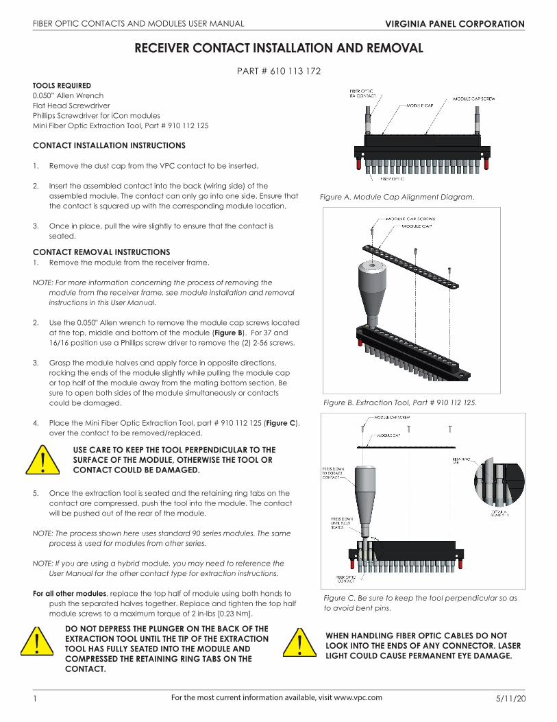
Figure B. Extraction Tool, Part # 910 112 125.
Figure A. Module Cap Alignment Diagram.
TOOLS REQUIRED0.050” Allen WrenchFlat Head ScrewdriverPhillips Screwdriver for iCon modulesMini Fiber Optic Extraction Tool, Part # 910 112 125
CONTACT INSTALLATION INSTRUCTIONS
1. Remove the dust cap from the VPC contact to be inserted.
2. Insert the assembled contact into the back (wiring side) of theassembled module. The contact can only go into one side. Ensure thatthe contact is squared up with the corresponding module location.
3. Once in place, pull the wire slightly to ensure that the contact isseated.
CONTACT REMOVAL INSTRUCTIONS1. Remove the module from the receiver frame.
NOTE: For more information concerning the process of removing the module from the receiver frame, see module installation and removal instructions in this User Manual.
2. Use the 0.050" Allen wrench to remove the module cap screws locatedat the top, middle and bottom of the module (Figure B). For 37 and16/16 position use a Phillips screw driver to remove the (2) 2-56 screws.
3. Grasp the module halves and apply force in opposite directions,rocking the ends of the module slightly while pulling the module capor top half of the module away from the mating bottom section. Besure to open both sides of the module simultaneously or contactscould be damaged.
4. Place the Mini Fiber Optic Extraction Tool, part # 910 112 125 (Figure C),over the contact to be removed/replaced.
5. Once the extraction tool is seated and the retaining ring tabs on thecontact are compressed, push the tool into the module. The contactwill be pushed out of the rear of the module.
NOTE: The process shown here uses standard 90 series modules. The same process is used for modules from other series.
NOTE: If you are using a hybrid module, you may need to reference the User Manual for the other contact type for extraction instructions.
For all other modules, replace the top half of module using both hands to push the separated halves together. Replace and tighten the top half module screws to a maximum torque of 2 in-lbs [0.23 Nm].
Figure C. Be sure to keep the tool perpendicular so as to avoid bent pins.
USE CARE TO KEEP THE TOOL PERPENDICULAR TO THE SURFACE OF THE MODULE, OTHERWISE THE TOOL OR CONTACT COULD BE DAMAGED.
1
DO NOT DEPRESS THE PLUNGER ON THE BACK OF THE EXTRACTION TOOL UNTIL THE TIP OF THE EXTRACTION TOOL HAS FULLY SEATED INTO THE MODULE AND COMPRESSED THE RETAINING RING TABS ON THE CONTACT.
WHEN HANDLING FIBER OPTIC CABLES DO NOT LOOK INTO THE ENDS OF ANY CONNECTOR. LASER LIGHT COULD CAUSE PERMANENT EYE DAMAGE.

FIBER OPTIC CONTACTS AND MODULES USER MANUAL VIRGINIA PANEL CORPORATION
5/11/20For the most current information available, visit www.vpc.com
ITA CONTACT INSTALLATION AND REMOVAL
PART # 610 113 173
TOOLS REQUIREDMini Fiber Optic Extraction Tool, Part # 910 112 125
CONTACT INSTALLATION INSTRUCTIONS
1. Remove the dust cap from the VPC contact to be inserted.
2. Insert the assembled contact into the back (wiring side) of themodule. Push the contact forward until the crimp is inside the modulehousing. Once in place, pull the wire slightly to ensure the contact isseated.
3. Reinstall dust cap.
CONTACT REMOVAL INSTRUCTIONS
1. Remove the module from the ITA frame.
NOTE: For more information concerning the process of removing the module from the ITA frame, see module installation and removal instructions in Section 2 of this User Manual.
2. Place the Mini Fiber Optic Extraction Tool, part # 910 112 125 (FigureA) over the contact to be removed/replaced. Use care to keep thetool perpendicular to the surface of the module, otherwise the tool orcontact could be damaged. Rotate the tool slightly while pushing itinto the counter bore on the mating side of the module.
3. Once the extraction tool is seated properly and the retaining ringtabs on the contact are compressed, push the tool into the module.The contact will be pushed out of the rear of the module (Figure B).
NOTE: The process shown here uses standard/90 series modules. The same process is used for modules from other series.
NOTE: If you are using a hybrid module, you may need to reference the User Manual for the other contact type for extraction instructions.
Figure B. Be sure to keep the tool perpendicular to avoid bent pins.
Figure A. Extraction Tool, Part # 910 112 125.
WHEN HANDLING FIBER OPTIC CABLES DO NOT LOOK INTO THE ENDS OF ANY CONNECTOR. LASER LIGHT COULD CAUSE PERMANENT EYE DAMAGE.
DO NOT DEPRESS THE PLUNGER ON THE BACK OF THE EXTRACTION TOOL UNTIL THE TIP OF THE EXTRACTION TOOL HAS FULLY SEATED INTO THE MODULE AND COMPRESSED THE RETAINING RING TABS ON THE CONTACT.
2
FIBER OPTIC CONTACTS AND MODULES USER MANUAL VIRGINIA PANEL CORPORATION
5/11/20 For the most current information available, visit www.vpc.com
STRAIN RELIEF GUIDEPART # 510 109 116/ 510 109 298/ 510 109 296
STRAIN RELIEF GUIDELINES
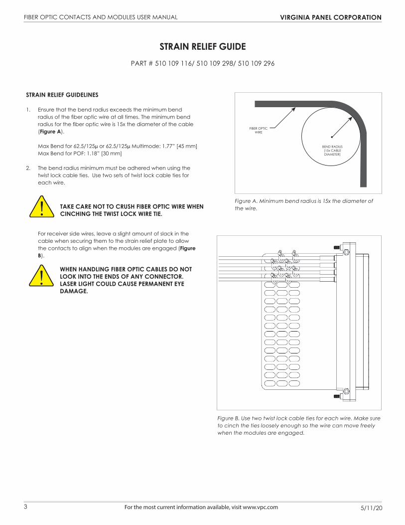
1. Ensure that the bend radius exceeds the minimum bendradius of the fiber optic wire at all times. The minimum bendradius for the fiber optic wire is 15x the diameter of the cable(Figure A).
Max Bend for 62.5/125µ or 62.5/125µ Multimode: 1.77” [45 mm]Max Bend for POF: 1.18” [30 mm]
2. The bend radius minimum must be adhered when using thetwist lock cable ties. Use two sets of twist lock cable ties foreach wire.
For receiver side wires, leave a slight amount of slack in the cable when securing them to the strain relief plate to allow the contacts to align when the modules are engaged (Figure B).
Figure A. Minimum bend radius is 15x the diameter of the wire.
Figure B. Use two twist lock cable ties for each wire. Make sure to cinch the ties loosely enough so the wire can move freely when the modules are engaged.
FIBER OPTICWIRE
BEND RADIUS(15x CABLEDIAMETER)
WHEN HANDLING FIBER OPTIC CABLES DO NOT LOOK INTO THE ENDS OF ANY CONNECTOR. LASER LIGHT COULD CAUSE PERMANENT EYE DAMAGE.
TAKE CARE NOT TO CRUSH FIBER OPTIC WIRE WHEN CINCHING THE TWIST LOCK WIRE TIE.
3

FIBER OPTIC CONTACTS AND MODULES USER MANUAL VIRGINIA PANEL CORPORATION
5/11/20 For the most current information available, visit www.vpc.com
90 SERIES MODULE INSTALLATION AND REMOVALPART # 510 104 120/ 510 104 150/ 510 104 243/ 510 104 301
510 108 111/ 510 108 132/ 510 108 210/ 510 108 276
TOOLS REQUIRED3/32 Allen Wrench
INSTALLATION INSTRUCTIONS
1. Place the module in the receiver or ITA until the upper andlower module screws touch the mating holes in the innerframe. Ensure that Pin 1 is located at the top for systems inwhich the modules are oriented vertically or to the left forsystems in which the modules are oriented horizontally.
2. Using a 3/32 Allen wrench, tighten the top screw 1 to 2 fullrevolutions, while pushing lightly against the face of themodule.
3. Maintain this pressure while tightening the bottom screw 1 to2 full revolutions.
4. Repeat this sequence until the module is seated. Torque thescrew to 4 in-lbs [0.23 Nm].
REMOVAL INSTRUCTIONS
1. To remove, loosen the top screw 1 to 2 full revolutions. Loosenbottom screw 1 to 2 full revolutions.
2. Repeat this sequence until the module is separated from thereceiver or ITA.
Note: For optimum performance and system longevity, distribute the contact load evenly throughout the module.
Figure A. Receiver Module.
Figure B. ITA Module.
POSITION 1
WHEN HANDLING FIBER OPTIC CABLES DO NOT LOOK INTO THE ENDS OF ANY CONNECTOR. LASER LIGHT COULD CAUSE PERMANENT EYE DAMAGE.
4

FIBER OPTIC CONTACTS AND MODULES USER MANUAL VIRGINIA PANEL CORPORATION
5/11/20For the most current information available, visit www.vpc.com
TOOLS REQUIREDPhillips Head Screwdriver
INSTALLATION INSTRUCTIONS
NOTE: The receiver strain relief plate or the ITA cover may need to be removed prior to installing or removing an iCon module. Please refer to the appropriate User Manual for instructions on how to perform these steps.
1. Place the module in the receiver or ITA until the upper and lowermodule screws touch the mating holes in the inner frame. Installmodules such that Position 1 is located at the top of the ITA/receiver frame.
2. Using a Phillips head screwdriver, tighten the top screw 1 to 2 fullrevolutions, while pushing lightly against the face of the module.
3. Maintain this pressure while tightening the bottom screw 1 to 2 fullrevolutions.
4. Repeat this sequence until the module is seated. Torque thescrew to 1.5 in-lbs [0.16 Nm].
REMOVAL INSTRUCTIONS
1. To remove, loosen the top screw 1 to 2 full revolutions. Loosenbottom screw 1 to 2 full revolutions.
2. Repeat this sequence until the module is separated from thereceiver or ITA.
NOTE: For optimum performance and system longevity, distribute the contact load evenly throughout the module.
ICON MODULE INSTALLATION AND REMOVALPART # 510 161 102/ 510 161 103/ 510 161 104
510 160 102/ 510 160 103/ 510 160 104
Figure A. Receiver Module.
Figure B. ITA Module.
WHEN HANDLING FIBER OPTIC CABLES DO NOT LOOK INTO THE ENDS OF ANY CONNECTOR. LASER LIGHT COULD CAUSE PERMANENT EYE DAMAGE.
5

FIBER OPTIC CONTACTS AND MODULES USER MANUAL VIRGINIA PANEL CORPORATION
5/11/20For the most current information available, visit www.vpc.com
MULTIMODE RECEIVER CONTACT CLEANING GUIDEPART # 910 121 192/ 610 113 172
TOOLS REQUIRED910 121 192 Tool, Fiber Optic Cleaning Pen, Multimode Glass Fiber, Receiver/ITA
RECEIVER CONTACT CLEANING INSTRUCTIONS
NOTE: Pen tool is the preferred tool for cleaning fi ber contact tips.
1. Remove Guide Cap from Pen Tool as shown in (Figure A).
2. Insert tip of Pen Tool into the receiver contact as shown in (Figure B).
3. Grasp Pen Tool body and push forward to start cleaning the contact end face.A click sound indicates the end of the cleaning process. Put Guide Cap on afteruse.
Continued on next page...
Figure B. Insert Pen Tool into the receiver contact.Figure A. Remove Guide Cap.
PEN TOOL BODYGUIDE CAP
PUSH FORWARD
RECEIVERCONTACT
CLICK SOUND =CLEANING FINISHED
WARNING: BE CAREFUL NOT TO SLANT THE PEN TOOL WHILE INSERTING INTO CONTACT.
WARNING: DO NOT USE TOO MUCH FORCE DURING THE INSERTION OF THE PEN TOOL INTO THE CONTACT. THIS MAY CAUSE DAMAGE TO CONTACT AND PEN TOOL.
WARNING: IF PUSHING THE PEN TOOL BODY FORWARD IS INHIBITED, STOP AND ENSURE THAT THERE IS NO DEBRIS INHIBITING THE CLEANING PROCESS.
6

FIBER OPTIC CONTACTS AND MODULES USER MANUAL VIRGINIA PANEL CORPORATION
5/11/20For the most current information available, visit www.vpc.com
MULTIMODE ITA CONTACT CLEANING GUIDE PART # 910 121 192/ 610 113 173
TOOLS REQUIRED910 121 192 Tool, Fiber Optic Cleaning Pen, Multimode Glass Fiber, Receiver/ITA
ITA CONTACT CLEANING INSTRUCTIONS
NOTE: Pen tool is the preferred tool for cleaning fi ber contact tips.
1. Remove Guide Cap Cover from Guide Cap on Pen Tool as shown in (Figure A).
2. Insert ITA contact into Guide Cap as shown in (Figure B).
3. Grasp Pen Tool body and push forward to start cleaning the contact end face.A click sound indicates the end of the cleaning process. Put cover back on afteruse.
Figure B. Insert ITA contact into Guide CapFigure A. Remove Guide Cap Cover.
PEN TOOL BODY
GUIDE CAP
GUIDE CAP COVER
PUSH FORWARD
ITACONTACT
CLICK SOUND =CLEANING FINISHED
GUIDE CAP
WARNING: BE CAREFUL NOT TO SLANT THE PEN TOOL WHILE INSERTING INTO CONTACT.
WARNING: DO NOT USE TOO MUCH FORCE DURING THE INSERTION OF THE PEN TOOL INTO THE CONTACT. THIS MAY CAUSE DAMAGE TO CONTACT AND PEN TOOL.
WARNING: IF PUSHING THE PEN TOOL BODY FORWARD IS INHIBITED, STOP AND ENSURE THAT THERE IS NO DEBRIS INHIBITING THE CLEANING PROCESS.
7
8
FIBER OPTIC CONTACTS AND MODULES USER MANUAL VIRGINIA PANEL CORPORATION
5/11/20 For the most current information available, visit www.vpc.com
CONTACT AND MODULE CAREPART # 510 108 189/ 510 109 295/ 510 104 227/ 510 109 294
ALL MINI COAX MODULES
The cleanliness of the Fiber Optic contacts is extremely critical to maintain high performance and extended life. Modules should be cleaned before initial usage and then after any extended storage period. The dust cover should be in place at any time the ITA is not mated with the receiver. Also, the contacts should be cleansed whenever questionable readings are encountered.
NOTE: Pen tool from pages 7 and 8 is the preferred tool for cleaing fiber contact tips.
MAKE SURE ALL LASER LIGHT SOURCES ARE TURNED OFF BEFORE CLEANING. LASER LIGHT CAN PERMANENTLY DAMAGE YOUR EYES.
FOLLOW MANUFACTURER’S DIRECTIONS ON PRESSURIZED CANS. DO NOT TIP OR SHAKE CAN DURING USAGE.
WEAR SAFETY GLASSES AND GOGGLES WHEN CLEANING THE MODULES. PARTICLES AND/OR ALCOHOL COULD BE PROJECTED INTO YOUR EYES BY THE PRESSURIZED CLEANER.
CLEANING INSTRUCTIONS FOR THE ITA FIBER OPTIC MODULE FOR INSTALLED CONTACTSRecommended Kit: VPC Part # 910 121 170
1. Remove the dust caps from the ITA contacts.2. Use a can of optical grade pressurized duster to clean the module by thoroughly spraying the inside of the casing containing the
termini.3. Saturate a clean foam tip with optical grade alcohol and wipe the end of an individual contact.4. Immediately dry the contact with a dry foam tip.5. Repeat the alcohol cleansing process for all existing contacts.6. Reinstall the dust cap on the ITA contact.
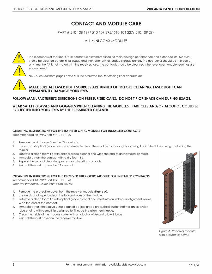
CLEANING INSTRUCTIONS FOR THE RECEIVER FIBER OPTIC MODULE FOR INSTALLED CONTACTSRecommended Kit: VPC Part # 910 121 170Receiver Protective Cover, Part # 510 109 501
1. Remove the protective cover from the receiver module (Figure A).2. Use an alcohol wipe to clean the top and sides of the module.3. Saturate a clean foam tip with optical grade alcohol and insert into an individual alignment sleeve,
wipe the end of the contact.4. Immediately dry the sleeve using a can of optical grade pressurized duster that has an extension
tube ending with a small tip designed to fit inside the alignment sleeve.5. Clean the inside of the module cover with an alcohol wipe and allow it to dry.6. Reinstall the dust cover on the receiver module.
Figure A. Receiver module with protective cover.
8

FIBER OPTIC CONTACTS AND MODULES USER MANUAL VIRGINIA PANEL CORPORATION
5/11/20 For the most current information available, visit www.vpc.com
RECEIVER CONTACTS
STA
ND
ARD
/ 90
SERI
ES R
ECEI
VER
MO
DU
LES
ICO
N R
ECEI
VER
MO
DU
LES
EXTR
ACTI
ON
CLEA
NIN
G
CLEA
NIN
G
STA
ND
ARD
/ 90
SERI
ES M
OD
ULE
PR
OTE
CTIV
E CO
VER
510
104
120
510
104
150
510
104
301
510
104
243
510
160
102
510
160
103
510
160
104
910
112
125
910
121
170
910
121
192
510
109
501
610 113 170 X X X X X X X X X X
610 113 172 X X X X X X X X X X X
CROSS REFERENCE TABLES
ITA CONTACTS
STA
ND
ARD
/ 90
SER
IES
ITA
MO
DU
LES
ICO
N IT
A M
OD
ULE
S
EXTR
ACTI
ON
CLEA
NIN
G
CLEA
NIN
G
510
108
111
510
108
132
510
108
276
510
108
210
510
161
102
510
161
103
510
161
104
910
112
125
910
121
170
910
121
192
610 113 171 X X X X X X X X X
610 113 173 X X X X X X X X X X
9

FIBER OPTIC CONTACTS AND MODULES USER MANUAL VIRGINIA PANEL CORPORATION
5/11/20 For the most current information available, visit www.vpc.com
CONTACT PERFORMANCE SPECIFICATIONS
Specifications
INSERTION LOSS - PLASTIC OPTICAL FIBER (POF) -4.0 db Max / Mated Pair
INSERTION LOSS - GLASS FIBER -1.5 db Max / Mated Pair
POF DIAMETER 980/1000 µm
GLASS FIBER DIAMETER Multimode 62.5/125 µm, 50/125 µm
Mechanical Characteristics
CYCLE LIFE 5,000 Cycles
MATING FORCE - POF 2.07 lbs [0.68 kg]
MATING FORCE - GLASS FIBER 2.8 lbs [1.27 kg]
Material
CONTACT BODY - POF Nickel Silver
CONTACT BODY - GLASS FIBER Ceramic and Nickel Silver
10


![Threats to Fiber- Optic Infrastructures · lMCI targeting Verizon for brand damage [tap disclosures] ... Defending Fiber Optic InfrastructuresDefending Fiber Optic Infrastructures](https://img.pdfslide.us/doc/110x75/5acb82e77f8b9ab10a8b583f/threats-to-fiber-optic-targeting-verizon-for-brand-damage-tap-disclosures-.jpg)