Embed Size (px)
Citation preview

F80R Series
F70A Series
F70 Series
F71 Series
Simplified Wiring K Series
F70T Series
F70V Series
F71RAN
F2R Series
FLD1R
F10R-AT
Fiber Optic Cables
■
■
■
■
■
■
■
■
■
■
■
■
Fiber optic sensors
Fiber
opticsensors
1
HOME

2
Fiberopticsenso
rs
Type
Fiber Optic Sensor withSimplified-wiringconnection
Fiber Optic sensors
■ List of models
F70A/F70F71
K
F70
F2R
FLD
F10R-AT
Fiber Optic Slim typeamplifier
Fiber Optic Laser amplifier
Fiber Optic Pulseamplificationtype amplifier
Misselanious Fiber optic cables
Characteristics tables (directionalcharacteristics/distance-output characteristics)
Attachments
Series Appearance (typical example) Overview/characteristics
12
10
46
50
54
56
60
140
158
●Simplified wiring●Connectible up to 16 units●Mixed use of different models within series
available with no master/slave distinction●Space saving
●Digital display of sensing information●Advanced functions for optimization●Ultra-thin packaging
●Ultra-slim packaging●Only requiring space for cord●Low-cost
●High-degree of accuracy achievedwith red laser
●Equipped with light emission stopfunction
●Pulse amplification method used●Unaffected by background●Minute variation detected
●Various detection methods●Various applications/conditions
●Displaying optimum useConfigurations
●For wider range of applications andmore stable detection
See page
Fiber Optic Sensor withDigital display
F70A 8●Digital display●High-sensitivity/high-accuracy●Ultra-thin packaging
F71RANFiber Optic Analog outputamplifier
42
●Fine-adjustment of output achievedwith 8-turn adjustment
●Ultra-thin packaging
F70TFiber Optic Sensor withTwo-outputamplifier
●Digital display of sensing information●Two-output/modes allows for various
detection scenarios●Ultra-thin packaging
18
F70VFiber Optic Sensor withpreset counter
●Equipped with two up/down presetcounter circuits
●Sensor on/off output and presetcounter output provided
36
F80RFiber Optic Sensor withDigital display
4
●Simple operation, low-cost●Selectable between long-distance and
high-speed modes according to purpose●Large digital display
●Anti Interference feature allowingadjacent installation of up to 8 units
●High accuracy 8-turn adjustment●Ultra-thin packaging
F71Thin Fiber Optic Sensor withmanualadjustment

3
Fiberopticsenso
rs
Fiber Optic sensors
■ Applications
● Positioning of wafers
● Detection of level of liquid inpipe
Sensor
● Detection of screw-in amountof screw
Elbow-shaped fiber optic cable
● Detection of glass plate atoutlet of furnace
● 300-mm wafer mapping detection
Double-beam
● Detection of level of liquid intank
● Detection of teabag strings
● Bad mark detection
● Checking for upside-downCD-ROMs
● Positioning of fluorescent tubes
● Label detection
● Distinction between sides ofcapacitors
Air nozzle

4
Fiberopticsenso
rs
F80RseriesDigital displayFiber optic sensors
● Simple operation and low cost design● “Long-distance” mode for dramatically
increased detecting distance● “Received light” indication enlarged
by about 8 times (compared withconventional Takex product)
● Larger digital display allows forsimple adjustment
● Low power consumption achieved
■ Type
■ ApplicationsPositioning of fluorescent tubes Checking for upside-down electronic components
Detection of double feed of CDs Checking of presence of silver paste
Electrodes detected for positioning prior to marking fluorescenttubes.
Sides of electronic components determined on part chute.
Detection method/detectingdistance
Dependent on fiber opticcable
NPN output
F80R
PNP output
F80RPN
Light source
Red LED
Output mode
Opencollector
Operation mode
Light-ON/Dark-ONselectable
Model
Detected from the side with small spot beam. Small amount of paste detected with spot of 0.5 mm in diameter.

5
Fiberopticsenso
rs
F80Rseries
■ Simple Operation
■ Low Power Consumption Achievedthrough Energy-Saving Design
■ High-Speed, Long-Distance Capability
Switching between long-distance and high-speed modes
High-speed mode
Long-distance mode
Yellow LED in the middle illuminated to indicate long-distance mode
Power consumption comparison between F80 and conventional model
(Typical example)
Current consum
ption (mA
)
Operating voltage(V)
Conventional model
ECO mode ECO ECO modemode ECO mode
High-speed mode
Long-distance mode
Swith selectable mode; between high speed and longdistance according to the purpose of detection.
Response time
Detecting distance (when combined with fiber optic cable FR105BC)
High-speed mode
High-speed mode
Long-distance mode
Long-distance mode
Press
Press
Easy monitoring of operation level
Pressing the button once activates flashing indication of the current operation level.Pressing the button again brings the view back to the received light level indication.
The digital display features LED indication of about 4.5 times larger then conventional model.Orange LED is used instead of red, which is often used as a danger signal.
About 4.5 times largerLarge digital display for improved visibility
¡Lower power consumption of less than half of that of aconventional model (by utilizing ECO operation),achieving power consumption of about 15 mA at 24 V(in long-distance mode).
¡Dark illumination enabled during normal operation,(when viewing of digital display tends to be lessfrequent, has reduced power consumption down toabout 1/5 of that of illuminated digital display).

6
Fiberopticsenso
rs
F80Rseries
■ Input/Output Circuitand Connection
¡NPN output
Inte
rnal
circ
uit
Brown: 12-24 VDC
Black: OUTPUT
Blue: 0V
¡PNP output
Inte
rnal
circ
uit
Brown: 12-24 VDC
Black: OUTPUT
Blue: 0V
AmplifierModel: F80 Series
Receiver
Transmitter
hole Mounting bracket
oval hole
Illumination on light receiving surface: 3,500 lx (incandescent lamp)
1-5 adjacent units in operation: –25 - +55 °C / Over 5 adjacent units in operation: –25 - +50 °C
Storage: –40 - +70 °C (non-freezing)
35-85%RH (non-condensing)
IP40
10-55 Hz / 1.5 mm amplitude / 2 hours each in 3 directions
500 m/s2 / 3 times each in 3 directions
■ Environmental Specification
Env
ironm
ent
Ambient light
Ambienttemperature
Ambient humidity
Protective structure
Vibration
Shock
■ Rating/Performance/Specification
Light-ON/Dark-ON selectable with sliding switch
Off delay/disabled selectable with sliding switch
Delay time: 45 ms fixed
High-speed mode: 190 µs s or less / Long-distance mode: 1.8 ms or less
Power supply
Power consumption
Output mode
Operation mode
Response time (*1)
Type
Model
Timer
NPNoutput
F80R
Red LED (680 nm)
Operation indicator: orange LED / Mode indicator: yellow LED / Teaching indicator: green LED
Received light level: 4 digits in orange LED (0-8000)
Output mode selector switch x 1 / Timer selector switch: 1 /
Teaching and sensitivity adjustment push + 4-direction button switch x 1
Full auto teaching / Auto teaching
Provided (manual sensitivity adjustment)
Reverse connection protection / Short circuit protection /Serge absorption
Polycarbonate
Permanently attached cord (Outer dimension: dia.3.7) 0.2sq. 3 core 2m length
Approx. 60 g (including 2-m cord and mounting bracket)
Mounting bracket / Operation manual
PNPoutput
F80RPN12-24V DC ±10% / Ripple 10% or less
Rat
ing/
perf
orm
ance
Spe
cific
atio
n
Light source (wavelength)
Indicator
Display
Switch
Sensitivity setting
Sensitivity adjustment function
Protection circuit
Material
Wiring
Mass
Accessory
■ Dimensions (in mm)
650 mW max. (25 mA max. at 24 V)
NPN open collector
Rating: sink current 100 mA (30 VDC max.)
Residual voltage: 1 V or less
830 mW max. (32 mA max. at 24 V)
PNP open collector
Rating: source current 100 mA (30 VDC max.)
Residual voltage: 2 V or less
(*1) For initial setting and checking, output operation is disabled for about 1.5 seconds after power-up.The operation mode factory setting is long-distance mode.

7
Fiberopticsenso
rs
●Operation panel
Teaching indicator (green LED):Flashes/illuminated during teaching.
Mode indicator (yellow LED):Illuminated when the long-distance modeis selected. Not illuminated in the high-speed mode.
Operation indicator (orange LED):Illuminated when the output is activated.
Received light level indication:The received light level is indicated in a 4-digit number between 0 and 8000.The number indication is slow for ease of reading. For instantaneous light reception (or
light blocking), even slower indication is given for the level of received light for lightreception (or light blocking).For an application in which the sensor output alternates between on and off consecu-tively, the levels of received light for light reception and blocking are alternately displayed.
ECO operation:The number indication is illuminated brightly immediately after power-up or during switchoperation. When about 7 seconds have passed after power-up or end of switch operation, thenumber indication is dimmed and the mode enters the ECO operation state requiring less power.
Button switch:Used for teaching or sensitivity adjustment. The buttoncan be pressed downwards and in 4 directions.
Timer selector switch:Switched for selecting the off-delay timer.OFFD. :Off delay timer enabledNORM. :Timer disabled
Light-ON/Dark-ON selector switch:Selects an output mode.
L.ON:Light-ON (output activated when light is received)D.ON :Dark-ON (output activated when light is blocked)When the mode is switched with the power on, turn off the power onceand back on or manually repeat turning on and off.
●Sensitivity setting■The setting condition is displayed after sensitivity setting has been completed:
good [Good] Optimum teaching achieved.high [High] Maximum sensitivity set.HArd [Hard] The hysteresis is small and the setting is severe.
This indication is also given for positioning teaching.SAtu [Saturated] The power is too high and the teaching condition is not optimum.
Replacing with a thinner fiber optic cable is recommended when a thickcable is used. Use in the high-speed mode is recommended when thelong-distance mode is selected.
■Sensitivity setting using stationary work<auto teaching>[Reflective type]①With no work placed, press and hold
down the button for 3 seconds.The indication rotates in the order of 1→2→3→SEt.
When SEt appears, release the button.②Place the work in a given position and
press the button.When SEt appears, release thebutton to complete sensitivity setting.[Note] The steps in the sensitivity settingprocess described above may bereversed by pressing the button first with the work placed.
■Sensitivity setting using moving work<full auto teaching>①Press and hold down the
button for 3 seconds.The indication rotatesin the order of 1→2→3→SEt.When SEt appears,release the button.
■ For Correct UseBe sure to follow the instructions in the operation manual provided for correct use of the product.
F80Rseries
Teaching indicator
Operation indicatorReceiver light level indication
Button switchTimer selector switch
Light-ON/Dark-ON selector switch
Mode indicator
②Press and hold the button for 3 seconds again.
・SEt is shown while the button isheld down.・Release the button when Auto
appears.
③The LEDs alternately flash to indicateactivation of full auto teaching. Letthe work pass in this condition.There is no time limit.
④Press the button to completesensitivity setting.
■Maximum sensitivity setting[Through-beam type]
Use a work, etc. to black the light. Set the sensitivity in this condition.[Reflective type]
Use of a reflective-type fiber optic cable at the maximum sensitivity maycause inadequate light blocking. Be sure to use a work for sensitivitysetting.
●Sensitivity adjustment (manual adjustment of activation level)<The value for the flashing number can be changed by pressing the button.>
①Press the button once.The current activation levelappears, allowing changing of theflashing number.・Pressing in the + direction
increases the activation level =SENS DOWN.・Pressing in the - direction decreases the activation level = SENS
UP[Note] Holding down the button changes the indication faster.・Pressing the button in the ▲ or ▼ direction shifts the active digit .②When the adjustment is finished, press the button once to complete
sensitivity setting.
●Activation level checking (for finding the current activation level)
①Press the button once.The number flashes and theactivation level is shown.
・For Light-ON, the value for thelevel that activates the outputfor light reception is displayed.・For Dark-ON, the value for the level that activates the output for
light blocking is displayed.
②Press the button once to complete sensitivity setting.
●Switching between the long-distance andhigh-speed modes
Press and hold down the button forabout 5 seconds.When Long or H-SP appears onthe display, release the button tocomplete switching.
D ONL ON
OFF DNORM
TAKEX
TAKEX
D ONL ON
OFF DNORM
TAKEX
D ONL ON
OFF DNORM
Green LED flashes
Received lightlevel indication
3 seconds1→
2→3→
SEt
D ONL ON
OFF DNORM
TAKEX
TAKEX
TAKEX
D ONL ON
OFF DNORM
D ONL ON
OFF DNORM
3 seconds
LEDs on the sidesalternately flashes
Received light level indication
LEDs on the sidesalternately flashes
D ONL ON
OFF DNORM
TAKEX
D ONL ON
OFF DNORM
TAKEX
D ONL ON
OFF DNORM
TAKEX
D ONL ON
OFF DNORM
TAKEX
D ONL ON
OFF DNORM
TAKEX
5 seconds
Yellow LED in the middle illuminatedto indicate long-distance mode
High-speed mode
Long-distance mode
D ONL ON
OFF DNORM
TAKEX
TAKEX
D ONL ON
OFF DNORM
Green LED flashes
Received light level indication
3 seconds1→
2→3→
SEt

● Digital indication of sensing information● Simple operation for setting functions● Direct reading of stablility level is
available along with received light leveland displace-ment indications
● LCD with backlight for ease of reading● Various convenient functions provided
● Full auto/auto teaching● Anti Mutual Interference● Manual sensitivity setting● Off-delay timer
F70Aseries
Variation
Simple operation Simple operation featured
Type
Digital display
general-
purpose type
NPN output
F70AR
F70AG
F70AB
F70AW
PNP output
F70ARPN
F70AGPN
F70ABPN
F70AWPN
Light source
Red LED
Green LED
Blue LED
White LED
Output mode
Open collector
(NPN/PNP)
Model
press
press
press
Received light level anddisplacement indicationsalternate every time the buttonis pressed “once.”
Self-diagnosisstability indication
Easily viewable color panel
Press “twice” for auto teachingand hold down for “3 seconds”for full auto teaching
Press and hold down for “3 seconds”for switching between operationmodes/light emission frequencychannels for Anti Mutual Interference.
Digital displayFiber optic sensors
8
Fiberopticsenso
rs

Detection
Output
40msoff-delay
A small object moving at a high speed can besecurely detected, thus allowing for a wider range of input conditions for the connected devices.
F70A
2 types of receivedlight level indication
Enhanced teaching features(sensitivity setting)
Secure detection of an instantaneous signal is ensured with the off-delay timer
The sensitivity position on the electronic volumeand the current received light level are displayed.There may be an error of ± 1-2 between the value onthe LCD and the actual value.
The level of received light is indicated in positive ornegative value with reference to the activation level.The activation level is taken as the reference (± 0) and the levelof received light with work used is indicated as a deviation fromthe reference in a positive or negative value.
Position on the electronicvolume: 8
The level of received light is indicated in 4-digit number.Min. = 0 / Max. = 1023
The example above shows that the current receive lightlevel is -123 with reference to the activation level.
Level indication mode Displacement indication mode
● Full auto teachingSimply pressing the button allows easy teaching; evenfor an object moving at a high speed.
● Auto teaching2-point teaching “with” and “without” the work allows thedetection of slight level difference such as the thicknessof a piece of work and the presence of a film.
● Position teachingThis feature is ideal for high-accuracy positioning thatrequires accurate determination of a detecting point.
● Maximum sensitivity settingFor applications requiring maximum sensitivity settingsuch as the detection of work with a through-beam typefiber optic cable, the extra-powerful light allows for usein an adverse environment.
● Manual settingArbitrary manual increase and decrease of a “set-point”allows level setting while checking the operation.
9
Fiberopticsenso
rs

Self-diagnosis stabilityindication
Function mode indicated
Operation/timer mode indicated
(6) 8-position sensing indicationwith electronic volume
Light emission frequencychannel switched forAntiMutual Interference feature
● Digital indication of sensing information
● Various advanced functions provide for
optimum use of the sensor
● Unparalleled “high resolution” allows
highly accurate detection
● LCD with backlight for ease of reading
● Longer detecting distance
(about 2-X that of a conventional Takex
model)
Variation
Excellent detectionperformance
Buitl-in high-resolution provides highly accuratedetection
Wide dynamic range and high resolution areachieved at the same timeHigh resolution is maintained even with a wide dynamic range.The provided electronic volume feature has both a wide dynamicrange and high resolution.
1 2 3 4 5 6 7 8
1024
Resolutionof 1024
Position on sensitivity volume
Detecting distance
Leve
l
The “electronic-volume” frequentlyswitches the sensitivity range, each ofwhich is divided into 1024 levels.
F70seriesDigital displayFiber optic sensors
Type
Digital display
high-performance
type
NPN output
F70R
F70G
F70B
F70W
PNP output
F70RPN
F70GPN
F70BPN
F70WPN
Light source
Red LED
Green LED
Blue LED
White LED
Output mode
Open collector
(NPN/PNP)
Model
10
Fiberopticsenso
rs

F70
Display function:(beyond received light level)
Displacement indication function Absolute value indication
supporting high resolution
Enhanced teaching features (sensitivity setting)
● Full auto teachingSimply pressing the button allows easy teaching of anobject moving at a high speed.The teach hold feature allows indication of themaximum and minimum data.
● Auto teaching2-point teaching with and without the presence of work,allows the detection of slight level differences such as thethickness of a piece of work and/or the presence of a film.
● Positioning teachingThis feature is ideal for high-accuracy positioning thatrequires accurate determination of a detecting point.
● Maximum sensitivity settingFor applications requiring a “maximum” sensitivity settingsuch as the detection of work with a through-beam type-fiber optic cable. The incorporated extra powerful lightwould allow use in an adverse environment.
● Manual settingArbitrary manual increase and decrease of a set-pointlevel allows level setting while checking the operation.
Auto sensing function compensates for adverse environmentThe level of received light is constantly monitored andfluctuation is detected and automatically adjusts theactivation/deactivation level.Stable detection at optimum sensitivity is ensured even ifthe received light level frequently fluctuates due to dust orwater drops.
Manual hysteresis setting featureThe hysteresis can be arbitrarily set according to theapplication, allowing setting of a small hysteresis forsevere, high-accuracy detection and a large hysteresis fordetection of large variation and prevention of chattering.
Timer functionsOn-delay, off-delay and on-off delay timer functions areprovided, which allows for a wide range of detecting andinput conditions from the connected devices.The delay time setting is variable between:10 ms, 20 ms, 40 ms, 60 ms, 80 ms, 100 ms and 120 ms.
Teach hold functionThe sensor has the ability to hold instantaneous data for anobject moving at a high rate of speed during full auto teaching.This data is displayed when the teaching has been completed.
All amplifiers should show “0” with no work.
Failure such as lightintensity degradationpossible if a negativevalue is shown.
Possible failure
Received light level indication going beyond the
If the received light level at light blockingis 10 and the level at light reception is6000, the light blocking / light receptionratio is calculated as 600 times.
87654321
9999
1024
Resolution of 1024
Position onelectronic volume
Detecting distance
Full range shown in valuesbetween 0 and 9999
Leve
l
The value for a deviation (positive or negative) ofreceived light level from the original level is shown atthe time of detection, which allows centralmanagement of sensors.
H 3 2 5 L 1 2 0
(Data for light reception is 325 and for light blocking 120.)
11
Fiberopticsenso
rs

Operation-mode switches betweenLight-ON and Dark-ON /timeroutput switch
Fine-tuning available with8-turn sensitivity adjustmentPosition indicator
8/4 switch for setting AntiInterference feature
Self-diagnosis stability indicationFlashes to indicate degradation
of received light intensity
● Adjacent installation of up to 8 units- Proprietary Anti Interference feature is used -
● High-accuracy-8-turn sensitivity adjustment- Position indicator is provided -
● High-speed response of 30 μs- H type sensor -
Variation
Manual highperformance model
High-accuracy 8-turn adjustment is equipped with aposition indicator, which allows direct reading of theadjustment position.
F71seriesManual setting Fiber optic sensors
Type
Manual settinggeneral-purposetype
Manual settinghigh-speed type
NPN outputF71RF71GF71BF71WF71RHF71GHF71BHF71WH
PNP outputF71RPNF71GPNF71BPNF71WPNF71RHPNF71GHPNF71BHPNF71WHPN
Light source
Red LEDGreen LEDBlue LEDWhite LEDRed LED
Green LEDBlue LEDWhite LED
Output mode
Open collector
(NPN/PNP)
Model
12
Fiberopticsenso
rs

F71
Useful 8-unit detection
Optical transmission-type AntiInterference feature
The Anti Interference feature prevents false operationdue to mutual interference even if up to 8 units areinstalled adjacently.
Anti Interference for up to 4sensors (response time: 250 μs)
Anti Interference for up to 8 sensors(response time: 500 μs, turbo functionenabled) Mutual interference
prevented by optical transmission when more than one unit is adjacently installed.
Light transmitted
Light received
ON
OFFON
OFFON
OFF
Normal operation (NOR)
On delay (ON.D)
Off delay (OFF.D)
120%
Activation level
Received light level
Detection output
Stability output
Stability indicatorFlashes
Easy-to-understand stability functionWhen four consecutive detections with a received light level of120% or lower of the activation level have occurred, the stabilityoutput is activated. At the same time, the stability indicator flashesan alert.
Timer operationA delay timer of about 40 ms is provided to allow for arange of input conditions of the connected devices.The timer is also useful for stabilization of detection outputsuch as canceling signal chattering.
Turbo function increases detecting distanceby 30%When it is desirable to increase the detecting distance forthe current condition of use, enabling the turbo functionallows a distance increase of about 30%.
8 4
8 4
Up 30%
13
Fiberopticsenso
rs

Type
End unit
Mounting bracket*
F70A・F70series
■ Type● Amplifier (main unit)
● Fiber optic cableFor different types of fiber optic cables, see pp. 59-.
● M8 connector typeM8 connector connection type is separately available for all models, which isidentified by “-J” following the model number. “-JE” and “-JS” are availabledepending on the input/output specification.For connector specifications, see p. 23.<Type of cords with M8 connector>・Model:FBC-4R2S (equipped with straight M8 connector and 2-m cord)・Model:FBC-4R2L (equipped with angled M8 connector and 2-m cord)
Model
FA7EU
AC-BF2
Description
DIN rail mounting stopper
Amplifier unit mounting bracket
End unit
● Optional parts
*Accessory
Type
Digital display
general-purpose type
Digital display
high-speed type
NPN output
F70AR
F70AG
F70AB
F70AW
F70R
F70G
F70B
F70W
PNP output
F70ARPN
F70AGPN
F70ABPN
F70AWPN
F70RPN
F70GPN
F70BPN
F70WPN
Light source
Red LED
Green LED
Blue LED
White LED
Red LED
Green LED
Blue LED
White LED
Open collector(NPN/PNP)
Output mode
Permanentlyattached cord M8 connector type
also available
ConnectionModel
14
Fiberopticsenso
rs

Rat
ing/
perf
orm
ance
F70A・F70series
■ Rating/Performance/Specification
Model
Power supply
Currentconsumption
Controloutput (*)
Stabilityoutput (*)
Operation mode
Timer
Response time
NPN type
PNP type
NPN type
PNP type
NPN type
PNP type
NPN type
PNP type
F70AR
F70ARPN
Open collector output / Rating: sink current 50 mA (30 VDC max.) / Residual voltage: 1 V or less
Open collector output / Rating: source current 50 mA (30 VDC max.) / Residual voltage: 2 V or less――――――
Light-ON/Dark-ON selectable
12-24V DC ±10% / Ripple 10% max.
39 mA max.
50 mA max.
Open collector output / Rating: sink current 100 mA (30 VDC max.) / Residual voltage: 1 V or less
Open collector output / Rating: source current 100 mA (30 VDC max.) / Residual voltage: 2 V or less
Light emission frequency channel 1: 600 μs max.Light emission frequency channel 2: 700 μs max.
Light emission frequency channel 1: 500 μs max.
Light emission frequency channel 2: 600 μs max.
Out
putm
ode
F70AG
F70AGPN
F70AB
F70ABPN
F70AW
F70AWPN
F70R
F70RPN
F70G
F70GPN
F70B
F70BPN
F70W
F70WPN
Off delay/disabled selectable
Delay time: 40 ms fixed
On delay/off delay/on-off delay/disabled selectable
Delay time: selectable between 10, 20, 40, 60, 80, 100 and 120 ms / Default: 40 ms
15
Fiberopticsenso
rs
Incandescent lamp: 10,000 lx / Sunlight: 20,000 lx
1-3 adjacent units in operation: -25 - +55 °C
4-10 adjacent units in operation: -25 - +50 °C
11-16 adjacent units in operation: -25 - +45 °C
Storage: -40 - +70 °C (non-freezing)
35-85%RH (non-condensing)
IP40
10-55 Hz / 1.5 mm amplitude / 2 hours each in 3 direction
500 m/s2 / 3 times each in 3 directions
Env
ironm
ent
■ Environmental Specification
Spe
cific
atio
n
Light source
(wavelength)
Indicator
Display
Switch
Sensitivity setting
Sensitivity setting input
Sensitivity adjustment function
Functions
Material
Connection
Mass
Accessory
Operation indicator: orange LED / Stability (STB) indicator: green LED
LCD display with backlight
Full auto teaching / Auto teaching
Set button input Set button input/external input
Provided (manual sensitivity adjustment)
Polycarbonate
For M8 connector specifications, see p. 23.
Permanently attached cord (outer dimension: dia. 4.8) 0.2sq. 3 core 2 m length Permanently attached cord (outer dimension: dia. 4.8) 0.2sq. 5 core 2 m length
Ambient light
Ambient
temperature
Ambient humidity
Protective structure
Vibration
Shock
Red LED
(660mm)
Green LED
(525mm)
Blue LED
(470mm)White LED
Red LED
(660mm)
Green LED
(525mm)
Blue LED
(470mm)White LED
2 set buttons / Mode selector switch: RUN/SET
Mounting bracket / Operation manual
(*) Avoid the transient condition (0.5 seconds) immediately after power-up for output.
● Anti Mutual Interference feature● Short circuit protection feature
● Sensor function: AUTO/TEACH/LOCK● Auxiliary function:
S for manual adjustment of sensitivity and activation levelH for manual hysteresis settingV for displacement indication and absolutevalue indication modes
● Anti Mutual Interference feature● Self-diagnosis feature● Short circuit protection feature
2 set buttons / Mode selector switch: RUN/SELECT/MODE
Approx. 80 g (including 2-m cord and mounting bracket)
Type
Manual setting
general-purpose type
Manual setting
high-speed type
Type
End unit
Mounting bracket*
F71series
NPN output
F71R
F71G
F71B
F71W
F71RH
F71GH
F71BH
F71WH
PNP output
F71RPN
F71GPN
F71BPN
F71WPN
F71RHPN
F71GHPN
F71BHPN
F71WHPN
Light source
Red LED
Green LED
Blue LED
White LED
Red LED
Green LED
Blue LED
White LED
Open collector
(NPN/PNP)
Output mode
Permanentlyattached cord
M8 connector typealso available
ConnectionModel
■ Type● Amplifier (main unit)
● Fiber optic cableFor different types and prices of fiber optic cables, see pp. 59-.
● M8 connector typeM8 connector connection type is separately available for all models.For identification, “-J” follows the model number.For connector specifications, see p. 23.<Type of cords with M8 connector>・Model:FBC-4R2S (equipped with straight M8 connector and 2-m cord)・Model:FBC-4R2L (equipped with angled M8 connector and 2-m cord)
Model
FA7EU
AC-BF2
Description
DIN rail mounting stopper
Amplifier unit mounting bracket
End unit
● Optional parts
*Accessory
16
Fiberopticsenso
rs

Env
ironm
ent
Incandescent lamp: 10,000 lx max. / Sunlight: 20,000 lx max.
1-3 adjacent units in operation: -25 - +55 °C
4-10 adjacent units in operation: -25 - +50 °C
11-16 adjacent units in operation: -25 - +45 °C
Storage: -40 - +70 °C (non-freezing)
35-85%RH (non-condensing)
IP40
Power supply line: 500 V / Cycle: 10 ms / Pulse duration: 1 μs
Radiation: 1 kV / Cycle: 10 ms / Pulse duration 1 μs (with noise simulator)
10-55 Hz / 1.5 mm amplitude / 2 hours each in 3 direction
100 m/s2 / 3 times each in 3 directions
1,000 VAC for 1 minute
500 VDC, 20 MΩ max.
F71series
■ Rating/Performance/Specification
■ Environmental Specification
Model
Power supply
Currentconsumption
Controloutput (*)
Stabilityoutput (*)
Operation mode
Timer
Response time
NPN type
PNP type
NPN type
PNP type
NPN type
PNP type
NPN type
PNP type
F71R
F71RPN
F71G
F71GPN
F71B
F71BPN
F71W
F71WPN
F71RH
F71RHPN
F71GH
F71GHPN
F71BH
F71BHPN
F71WH
F71WHPN
12-24V DC ±10% / Ripple 10% max.
35 mA max.
40 mA max.
Open collector output / Rating: sink current 100 mA (30 VDC max.) / Residual voltage: 1 V or less
Open collector output / Rating: source current 100 mA (30 VDC max.) / Residual voltage: 1 V or less
Open collector output / Rating: sink current 100 mA (30 VDC max.) / Residual voltage: 1 V or less
Open collector output / Rating: source current 100 mA (30 VDC max.) / Residual voltage: 1 V or less
Light-ON/Dark-ON selectable
On delay/off delay/disabled selectable
Delay time: about 40 ms fixed
With switch at 4 (turbo function disabled): 250 μs max.With switch at 8 (turbo function enabled): 500 μs max.
30 μs max. (*1)
Rat
ing/
perf
orm
ance
Out
putm
ode
Spe
cific
atio
n
Light source
(wavelength)
Indicator
Volume (VR)
Switch (SW)
Anti Mutual Interference
Short circuit protection
Material
Connection
Mass
Accessory
Operation indicator: orange LED / Stability (STB) indicator: green LED
SENS: sensitivity adjustment volume (8-turn without stopper equipped with indicator)
● Light-ON/Dark-ON selector switch: L.ON for Light-ON, D.ON for Dark-ON● Timer selector switch: NOR. for ON/OFF operation, ON.D for on delay (40 ms), OFF.D for of delay (40 ms)
Provided
Polycarbonate
Permanently attached cord (outer dimension: dia. 4.8) 0.2sq. 4 core 2 m length (-J type: M8 connector *2)
Approx. 90 g (including 2-m cord and mounting bracket)
Ambient light
Ambient
temperature
Ambient humidity
Protective structure
Noise
Vibration
Shock
Dielectric withstanding
Insulation resistance
Red LED
(660mm)
――――――
● Anti Mutual Interference/turbo mode selector switch (common)8:Anti Mutual Interference for up to 8 units, turbo function enabled4:Anti Mutual Interference for up to 4 units, turbo function disabled
Green LED
(525mm)
Blue LED
(470mm)White LED
Red LED
(660mm)
Green LED
(525mm)
Blue LED
(470mm)White LED
(*) Avoid the transient condition (0.5 seconds) immediately after power-up for output.(*1) The detecting distance for high-speed response H type is reduced to roughly 30% of the ordinary type.(*2) For details about -J (M8 connector type), see p. 23.
――――――Provided
Mounting bracket / Screwdriver for adjustment / Light shielding sticker (excluding H type) / Operation manual
17
Fiberopticsenso
rs

● Digital display
● Auto sensitivity setting
● Manual sensitivity setting
● The “new” simplified-wiring
connection system
employed for each major
amplifier model
Only one output wirerequired for 15 unitsModel F7K-1 uses adedicated outputconnector cord
Model F7K-3 power/outputconnector cord used for anyone of the units in group
Simplified Wiring Kseries
Power can be supplied collectively to all units in one group (up to 16 units) at once by simply feeding power supply to any unit though the connector.Stand-alone use is also available.No extra power supply lines required for additional units.
F70K Series
F70K Series
F70AK Series
F70AK Series
F71K SeriesF71K Series
Up to 16
units of “
mixed” m
odel
combinati
ons are
allowed
with
out
a mas
ter/sl
ave d
istincti
on 48 wires for conventionalmodels are now reduced to 18
wires
Power supplied to any unit, required output taken out of any unit
Convenient feature
(F70AKseries)
Simplified-wiring connection typeFiber optic sensors
18
Fiberopticsenso
rs

Simplified Wiring K Series
Trio
capa
ble
ofse
rvin
gal
ltyp
esof
dete
ctio
nne
eds Digital display general-purpose type
F70AK series
Digital display high-performance type
F70K series
Manual sensitivity settingGeneral-purpose type
High-speed type
F71K series
4 types of connector cords available according to input/output function required
Replacement of connector cords simply by detaching and attaching connectorswithout moving sensors
Innovativemini connector employed
● With model F7K-4 (4 leads for power supply, control output, stability output and ground)
BROWN:12 to 24VDCBLUE :0VBLACK :OUT PUTORANGE:STABILTY OUT
Brown: 12-24 VDCBlue: 0 V
Black: control outputOrange: stability output
● With model F7K-3 (3 leads for power supply, control output and ground)
BROWN:12 to 24VDCBLUE :0VBLACK :OUT PUTORANGE:STABILTY OUT
Brown: 12-24 VDCBlue: 0 V
Black: control output
● With model F7K-2 (2 leads for control and stability outputs)
BROWN:12 to 24VDCBLUE :0VBLACK :OUT PUTORANGE:STABILTY OUT
Black: control outputOrange: stability output
● With model F7K-1(1 lead for control output)
BROWN:12 to 24VDCBLUE :0VBLACK :OUT PUTORANGE:STABILTY OUT
Black: control output
Power/output connector cord
Dedicated output connector cord
19
Fiberopticsenso
rs

Type
Power supply /
output
Output only
Type
Digital displaygeneral-purpose
type
Digital displayhigh-performance
type
Manual settinggeneral-purpose
type
Manual settinghigh-speed type
Simplified Wiring K Series
NPN outputF70ARKF70AGKF70ABKF70AWKF70RKF70GKF70BKF70WKF71RKF71GKF71BKF71WKF71RHKF71GHKF71BHKF71WHK
PNP outputF70ARKPNF70AGKPNF70ABKPNF70AWKPNF70RKPNF70GKPNF70BKPNF70WKPNF71RKPNF71GKPNF71BKPNF71WKPNF71RHKPNF71GHKPNF71BHKPNF71WHKPN
Light source
Red LEDGreen LEDBlue LEDWhite LEDRed LED
Green LEDBlue LEDWhite LEDRed LED
Green LEDBlue LEDWhite LEDRed LED
Green LEDBlue LEDWhite LED
Open collector(NPN/PNP)
Output mode ConnectionModel
■ Type● Amplifier (main unit)
For the specification of connector cords, see p. 23.
Model
F7K-4
F7K-3
F7K-2
F7K-1
Description
4 leads: power supply, 0V, control output, stability output
3 leads: power supply, 0V, control output
2 leads: control output, stability output
1 lead: control output
2m
Cord length
● Specified connector cord
● Fiber optic cable
For different types and prices of fiber optic cables, see pp. 59-.
Type
End unit
Model
FA7EU
Description
DIN rail mounting stopper
● Optional parts
End unit
Simplified-wiringconnector type
specified connectorcord used
20
Fiberopticsenso
rs

Type
Model
Connector material
Cord
Mass
Simplified Wiring K Series
● Connection and connector cord● For simplified wiring, use the specified connector cord
separately available.
● Attachment of connector cord① Join fiber amplifiers.② Insert the connector cord into each amplifier until it clicks.
③ Attach caps on the power supply terminals on the sidesof the group of joined amplifiers.
● Detachment of connector cord① Cut the power supply to the fiber sensor.② Press down the lever of the connector cord to remove the
cord.
● To extend the cord, use wires of at least 0.3mm2 and limit the length to within 100 m
● Connector pin short circuit protectionFor stand-alone or joined use of amplifiers, be sure to attach
the terminal caps that come with amplifiers to the terminals
on the ends of a unit or group of units to prevent electrical
shock or short circuit with power supply terminals on the
back.
Terminal caps are in two types: convex and concave.
● The connector cord can be attached or detached as amplifiersare joined together without sliding them to either side.
● For the dimensions of connector cords, see p. 34.
● Connection diagram
Power/output connector cord
F7K-4
50
Polycarbonate
Cord length: 2 m
Outer diameter:4 mm
(0.2sq. 4 core)
Outer diameter:4 mm
(0.2sq. 3 core)
Outer diameter:4 mm
(0.2sq. 2 core)
Outer diameter:2.6 mm
(0.2sq. 1 core)
Approx. 55 g Approx. 50 g Approx. 45 g Approx. 20 g
F7K-3 F7K-2
Dedicated output connector cord
F7K-1
Brown: 12-24 VDC
Blue: 0V
Black: control output
Black: control output
Orange: stability output
Black: control output
Insert
Remove
Press down
Lever
Terminal cap (convex)
Terminal cap(concave)
■ For Correct UseBe sure to follow the instructions in the operation manual provided for correct use of the product.
Brown: 12-24 VDC
Blue: 0V
Black: control output
Orange: stability output
With power/output connector cord model F7K-4
With power/output connector cord model F7K-3
Dedicated output connector cord model F7K-2
Dedicated output connector cord model F7K-1
21
Fiberopticsenso
rs
Maximum number ofattachments and
detachments of connector

Output circuit diagramModel
NPN output typeF70AR F70ABKF70AG F70AWKF70ABF70AWF70ARKF70AGK
■ Input/Output Circuit and Connection
PNP output typeF70ARPN F70ABKPNF70AGPN F70AWKPNF70ABPNF70AWPNF70ARKPNF70AGKPN
NPN output typeF70RF70GF70BF70W
PNP output typeF70RPNF70GPNF70BPNF70WPN
PNP output typeF70RKPNF70GKPNF70BKPNF70WKPN
Inte
rnal
circ
uit
Brown: 12-24 VDC
Black: OUT PUT
Blue: 0V
Inte
rnal
circ
uit
Brown: 12-24 VDC
Black: OUT PUT
Blue: 0V
Brown: 12-24 VDC
Pink: external teaching (*)
Black: OUT PUT
Blue: 0V
Orange: STB OUT
Inte
rnal
circ
uit
Brown: 12-24 VDC
Pink: external teaching (*)
Black: OUT PUT
Blue: 0V
Orange: STB OUT
Inte
rnal
circ
uit
Brown: 12-24 VDC
Black: OUT PUT
Blue: 0V
Orange: STB OUT
Inte
rnal
circ
uit
(*) When not using external teaching, cut the pink lead at thebase or connect it to the positive terminal (for NPN type) or 0V(PNP type) of the power supply.
22
Fiberopticsenso
rs

F71RKPNF71GKPNF71BKPNF71WKPNF71RHKPNF71GHKPNF71BHKPNF71WHKPN
Output circuit diagramModel
NPN output typeF70RKF70GKF70BKF70WK
■ Input/Output Circuit and Connection
■M8 Connector Type IO Specification/Pin Arrangement/Lead Colors
F71RF71GF71BF71WF71RHF71GHF71BHF71WH
F71RKF71GKF71BKF71WKF71RHKF71GHKF71BHKF71WHK
● Dimensions of cord with M8 connector (optional) (in mm)
2000
30.7
22 5
Color: black
557
φ9
FBC-4R2S (straight)
2000
Color: black
5523
φ9
23.7 16
7
FBC-4R2L (angled)
PNP output typeF71RPNF71GPNF71BPNF71WPNF71RHPNF71GHPNF71BHPNF71WHPN
Inte
rnal
circ
uit
Brown: 12-24 VDC
Black: OUT PUT
Blue: 0V
Orange: STB OUT
Inte
rnal
circ
uit
Brown: 12-24 VDC
Black: OUT PUT
Blue: 0V
Orange: STB OUT
1 3
42
White Black
BlueBrown
N.C (unused) Control output
0V12-24 VDC
F70A” -J”
1 3
42
White Black
BlueBrown
Stability output Control output
0V12-24 VDC
F71” -J”
1 3
42
White Black
BlueBrown
External teaching output Control output
0V12-24 VDC
F70” -JE”
1 3
42
White Black
BlueBrown
Stability output Control output
0V12-24 VDC
F70” -JS”
23
Fiberopticsenso
rs

Common to F70A/F70/F71 Series
Connector pin
Tab
End unit
Press
Click
Press
■ For Correct UseBe sure to follow the instructions in the operation manual provided for correct use of the product.
Press down
Press down
Pull
Press
④To detach the amplifiers, follow the steps in reverseorder and remove one amplifier at a time.
③To prevent the connections from coming loose dueto vibration, etc., attach end units (optional) on theends of the group of amplifiers to secure them.
①Opening the case coverWhile pressing down thefront part of the casecover, l ift the cover bypulling up the tab.
Just roughly pulling thecase cover tab for openingmay damage the cover.Be sure to press the frontpart of the cover whenpulling the tab.
● Handling of amplifier case cover
● Attaching amplifier on DIN rail or mounting bracket
● Attachment of amplifiers for joined use
②Attaching the coverPut the case cover on theamplifier as shown on thefigure on the right andpush in at the hinge.
①AttachmentPut the front hook of theamplifier on the rail (ormounting bracket) andpress down the back ofthe amplifier.
②DetachmentWhile pressing the amplifierforward, lift the front partand detach the front hook.
The cover opens up to theconnector on the back and staysat the half-opened position.
Pulling at the hinge with the coverhalf open allows removal of thecover.
Cover removed
Press down the front partof the cover until it clicksand make sure that thetab is hooked.
②Slide the amplifiers so that the tabs on the front andthe connector pins on the back are respectivelyjoined together.
①Mount one amplifier at a time on the DIN rail whilekeeping a certain space between amplifiers.
When using two or more amplifiers by joining them together, besure to use a DIN rail for mounting.Up to 16 units can be joined for use.Be sure to cut the power supply before attempting to join orseparate units.
The mounting bracket is optional.The amplifier cannot be side-mounted with a mounting bracketused.
Removing the amplifiers as they are joined together withoutsliding may damage the amplifiers.
24
Fiberopticsenso
rs

Common to F70A/F70/F71 Series
● Notes on usage
● Attachment of fiber optic cableAttachment to amplifier
Attachment of coaxial reflective fiber optic cable
1. Open the case cover and press down the single-touch lock
lever.
● When using two or more amplifiers joined together, be sure
to use a DIN rail for mounting.
Different ambient temperatures apply according to the
number of joined amplifiers.
● Be sure to turn off the power supply before wiring.● To extend the cord, use wires of at least 0.3 mm2 and limit
the length to within 100 m.● Using the same conduit for the amplifier wiring and power
transmission or high-voltage lines may cause faulty operation
or damage due to noise. Be sure to route them separately.● Make sure that the power fluctuation is within an allowable
range so that the power input will not exceed the rating.● When using a commercially-available switching regulator,
use the frame ground or ground terminal.● For output, avoid the transient condition (0.5 seconds)
immediately after power-up.● Do not use the sensor in a place subject to steam, large
amount of dust or direct exposure to water or oil.● Do not use the sensor outdoors or in a place subject to direct
disturbing light on the light receiving surface.● Use of a reflective-type fiber optic cable at the maximum
sensitivity may cause inadequate light blocking. Be sure to
use a work for sensitivity setting.
Attach the multi-core fiber to the receiver and single-core fiber
to the transmitter.
Attachment of small-diameter fiber optic cableWhen attaching a small-diameter fiber optic cable, use the
adapter that comes with the fiber optic cable.
2. Insert the fiber optic cable all the
way until it stops.
To prevent inadequate insertion of a
fiber optic cable, marks to indicate
the insertion length are provided on
the case side, which can be used as
gauges.
3. Lift the single-touch lock lever.
No. of amplifiers
1-3
4-10
11-16
Ambient temperature
-25 - +55 ºC
-25 - +50 ºC
-25 - +45 ºC
ReceiverTransmitter
Multi-core fiber
Single-core fiber
ReceiverTransmitter
Adapter
Fiber optic cableinsertion length:about 13 mm
■ For Correct UseBe sure to follow the instructions in the operation manual provided for correct use of the product.
25
Fiberopticsenso
rs

F70ASeries
Part names Operation
TAKEX F70AR
LDF
TL 12S
RUN SET
+
Stability indicator:
Operationindictor:
Operation mode
orange LED
green LED
LCD display
Function
Mode selector switch
Light emission frequency channels
SSet button +: black
SSet button –: red
L: Light-ONL: Lock
T: Sensitivity settingS: Sensitivity adjustment (manual)
D: Dark-ONF: Off delay
● Mode selector switchThis switch should be set to RUN for normal object detection, whichenables the lock mode and disables all operations on the sensor.Setting the mode selector switch to SET releases the lock, which allowsoperations on the sensor.
■ For Correct UseBe sure to follow the instructions in the operation manual provided for correct use of the product.
RUN SET+ -
RUN SET+ -
RUN SET+ -
L 1
L
3 seconds
RUN SET
LF
1
LF
1
Light emission frequencychannel indication
Lock released
Red button
Red button
Black button
Sensitivitysetting
Display modeswitching
Operation modeswitching
Light emission frequencychannel switching
Full auto teaching
Auto teaching
Once Twice
Hold downfor 3 seconds or longer
Switched every timebutton is pressed
→
→
→
→
→ → →
→ → → →
→
Mode selector switch Function and operation button Operation
↓ Press once
Press once
Switched every timebutton is pressed
Switched every timeblack button is pressed
Received lightlevel indicationDisplacementindication
Hold down black buttonfor 3 seconds or longerfor switching operationmodes & light emissionfrequency channels
Set the switch back to “RUN” for completion
Set the switch back to“RUN” for completion
Light-ON Light-ONOff delay
Dark-ON Dark-ONOff delay
CH.1 CH.2
12
L LF F
D D
1
L L 1
Lock indication
Mode selector switch
RUN SET+ -
26
Fiberopticsenso
rs

F70ASeries
● Sensitivity setting (teaching) ● Manual adjustment of activation level
● Maximum sensitivity setting: Press the red set button twice with the light blocked.
For displacement indication mode
For received light indication mode
Sensitivity adjustment completedThe mode automatically switches back to the lock mode about 10seconds after the sensitivity adjustment has been completed.
For through-beam type1.Block the light beam with a work, etc. to make the light blocking
state.2.Press the red set button twice.
●Work positioning setting1.Place the work at the desired position.2.With the work kept in place, press the red set button twice.
For reflective typeUse of a reflective-type fiber optic cable at the maximum sensitivitymay cause inadequate light blocking. Be sure to use a work forsensitivity setting.
Sensor operation can be monitored while adjusting the activation level,which allows setting of the optimum operation level.
Sensitivity setting using stationary work ― auto teaching
Sensitivity setting using moving work ― full auto teaching
Set the operation mode selector switch from RUN to SET.The lock is released and the sensor enters the sensitivity settingready state.
1.With no work placed, press the red set button and release it. Theindicator flashes, showing that the sensor is ready for the nextsetting input.
1.Press and hold down the red set button. The orange and greenindicators start flashing alternately and the flashing becomesslower after about 3 seconds.
2.Let the work pass while holding down the red set button.3.When the passing of the work and the slow flashing of the
indicators have been confirmed, release the set button.
Interference between sensors prevents correct sensitivity setting. Forcorrect sensitivity setting, make sure that there is no interference oflight by blocking the light from either of the sensors or removing thefiber optic cable from either of the amplifiers.
2.Place the work in a given position and press the red set button.
The indicator stops flashing, showing that sensitivity setting is
complete.
After setting the switch from RUN to SET (1),set it back to RUN (2).
The lock is released and the sensor enters
the sensitivity adjustment mode.
“S” flashes to
indicate that the
sensitivity can be
adjusted.Indicates that the activation level is “23.”
Activation level raised every time button ispressed = SENS DOWN
Activation level lowered every time button ispressed = SENS UP
Before adjustment, activation levelof “0” is shown.
The number is increased (decreased) everytime the black (red) set button is pressed.
■ For Correct UseBe sure to follow the instructions in the operation manual provided for correct use of the product.
RUN SET+ -
WorkFor reflective type
RUN SETFlashes
Release the red set button
About3 seconds
Indicators
Let work pass in this period
Flash flash flash flash Flash flash Flash lash Flash flash
L 1
L 1
L 1
↓
↓
RUN SET+ -
Once Twice
RUN SET+ -
Once TwiceReflective type
RUN SET
RUN SET
L 1 S S
+
-
RU
NS
ET
+
-
27
Fiberopticsenso
rs

F70Series
1T2
RUNSELECT
MODE
2 1
RUNSELECT
MODE
→ → → → → → → L LOF FOFO OF
L L D D D D
LDOF
ATL 12SHV
Operation mode
Function
Received light level Light emission frequency channel
Position on he electronic volume
8-step indication: 1, 2,.. 8
L:Light-OND:Dark-ONO:On delayF:Off delay
Part names Operation
Select between Light-ON and Dark-ON and timer operations.
3) Select a desired mode and set the switch back to RUN, whichenables the selected operation mode.
1) Set the switch from RUNto SELECT.
2) Press Button 2. The indication rotates in the order shownbelow by one step every time the button is pressed.
Shows the status and functions of the sensor including operationmode and received light level.
Sensor functionA: Auto senseT: TeachingL: Lock
● Mode selector switch
● Operation mode settingInitial (factory) settingWhen a fiber optic sensor has been mounted and power supplied for the first time, indications asshown below appear with the corresponding settings enabled:
Simple setting for immediate use
(For reflective type)1) Press Button 1 once with no work present.
The orange and green indicators flash.2) With the work in place, press Button 1 once
again.
(For through-beam type)1) Block the light beam with the work, etc. to set the
light blocking state.2) Press Button 1 twice. The setting is complete.
Use of a reflective-type fiber optic cable at the maximum sensitivitymay cause inadequate light blocking. Be sure work is present for autoor full auto teaching.
Sensor functionFunctions as an ordinary sensor.
Select function*Selection of Light-ON/Dark-On and timer operation.*Selection of sensor function.*Selection of auxiliary function.
Mode function*Sensitivity setting (teaching) in the lock mode*Activates the auxiliary function selected in [SELECT]
Auxiliary functionS: manual adjustment of sensitivity and activation levelH: manual hysteresis (deactivation level) settingV: displacement indication and absolute value indication
③……LCD display
■ For Correct UseBe sure to follow the instructions in the operation manual provided for correct use of the product.
Note
TAKEX F70R
LDOF
ATL 12SHV
RUNSELECT
MODE
2 1
Stabilityindicator
Operationindicator
Orange LED
Green LED
LCD display
Mode selectorswitch
Set button
Set button
L T 1Light-ONTeaching mode
Received light levelPosition on electronic volume: 8
RUNSELECT
MODE
2 1
Teaching with Button 1
SELECT
2 1
RUN MODEWork
RUNSELECT
MODE
RUNSELECT
MODE
RUNSELECT
MODE
TAKEX
LDOF
ATL 12SHV
RUNSELECT
MODE
2 1
RUN SELECT MODE
Operation modeselection
Teaching
TeachingThis position for ordinary detection
Auxiliary functionoperation
Set from RUN toMODE for
teaching mode
Or
Teaching w th Button 1
Teaching wi h Button 1
Output selectionwi h Button 2
Auxiliary function selectionw th Button 1
RUNSELECT
MODE
2 1
RUNSELECT
MODE
2 1
TAKEX F70R
LDOF
ATL 12SHV
RUNSELECT
MODE
2 1
TAKEX F70R
LDOF
ATL 12SHV
RUNSELECT
MODE
2 1
L
Indication Timer operationOutput operation
Light-ON None
LO Light-ON On delay
LF Light-ON On delay
LFO Light-ON On/Off delay
D Dark-ON None
DO Dark-ON On delay
DF Dark-ON Off delay
DO F Dark-ON On/Off delay
①……Stability indicator②……Operation indicator③……LCD display④……Operation mode⑤……Position on electronic volume⑥……Received light level⑦……Function⑧……Light emission frequency channel⑨……Mode selector switch
28
Fiberopticsenso
rs

F70Series
● Sensor function/auxiliary function settingSensor function selection1) Set the switch to SELECT.2) Press Button 1
The indication rotates in the order belowby one step every time the button ispressed, allowing the selection of a“sensor function” and “auxiliary function”.
3) Select a function and set the switch back to [RUN].The function selection is stored in the memory.
Sen
sor
func
tion
A: Auto sense mode Constantly monitors the level of receivedlight and, if any variation is found, theon/off level is automatically adjusted.
・The adjusted on/off level is not stored inthe memory. The initial data is appliedwhen the power supply is cut off onceand supplied again.
T: Teaching mode Allows sensitivity setting.The settingmethod options include “auto teaching,”“full auto teaching” and “external signal.”
L: Lock mode Prohibits sensitivity setting.
The level of received light with the workused is indicated in positive or negativevalue (displacement) with reference to thelevel of received light at the time ofteaching.
AVTVLV
Auxiliary function selection
● Select one of these functions and set the switch to [MODE], whichenables the auxiliary function selected.
Aux
iliar
yfu
nctio
n S: Allows adjustment of the “sensitivity” and “activation level” already set.
H: Allows adjustment of the hysteresis (deactivation level).
V: Indicates the absolute value.
D isp lacemen tindication mode
■ For Correct UseBe sure to follow the instructions in the operation manual provided for correct use of the product.
● Sensitivity setting (teaching)
1) Press Button 1 with no work placedand release the button. The indicatorflashes, showing that the sensor isready for the next teaching input.
2) With the work in place, press Button 1once and release it. The indicatorstops flashing, showing that sensitivitysetting is complete.
1) Press and hold down Button 1 for 3 seconds or longer.The orange and green indicators start flashing alternately and theflashing becomes slower a little later.
2) Let the work pass while holding down Button 1.3) When the passing of work and the slow flashing of indicators have
been confirmed, release Button 1.
Auto teaching (with stationary work)
Full auto teaching (with moving work)
Teach hold functionHolds momentary data during full auto teaching.
Releasing Button 1 showsthe maximum andminimum data duringteaching (the maximumand minimum values arealternately shown for about 3 seconds).This hold function is not available with the external teaching function.
Positioning teaching1) Place the work at the desired
position.
2) Press Button 1 twice,which completes the positioning.
● The received light level displayed on the LCD shows anaverage value for a certain period of time and may contain anerror of +/- 1-2.
● When the Anti Interference feature is enabled, the receivedlight level indication on the LCD may show an incorrect value.For correct indication, eliminate the interference by blockingthe light causing the interference or cutting of the power supplyto the sensor causing the interference and read the value.
Work
For reflective type
T 1
RUNSELECT
MODE
2 1
T
RUNSELECT
MODE
TAKEX F70R
ATL 12SHV
RUNSELECT
MODE
2 1
→ → → → → → → A AV → T
SV V H VT L L
A AV
AV
TV
LV
T TV
L LV
H325 L120
Maximumvalue
Minimumvalue
About 3seconds
Let work pass in this period
Set button 1 = ON (press)
Flash flash flash flashFlash flash Flash flash Flash flash
S
H
V
T 1
RUNSELECT
MODE
2 1
Work
For reflective type
● LCD display
29
Fiberopticsenso
rs
30
Fiberopticsenso
rs
F71Series
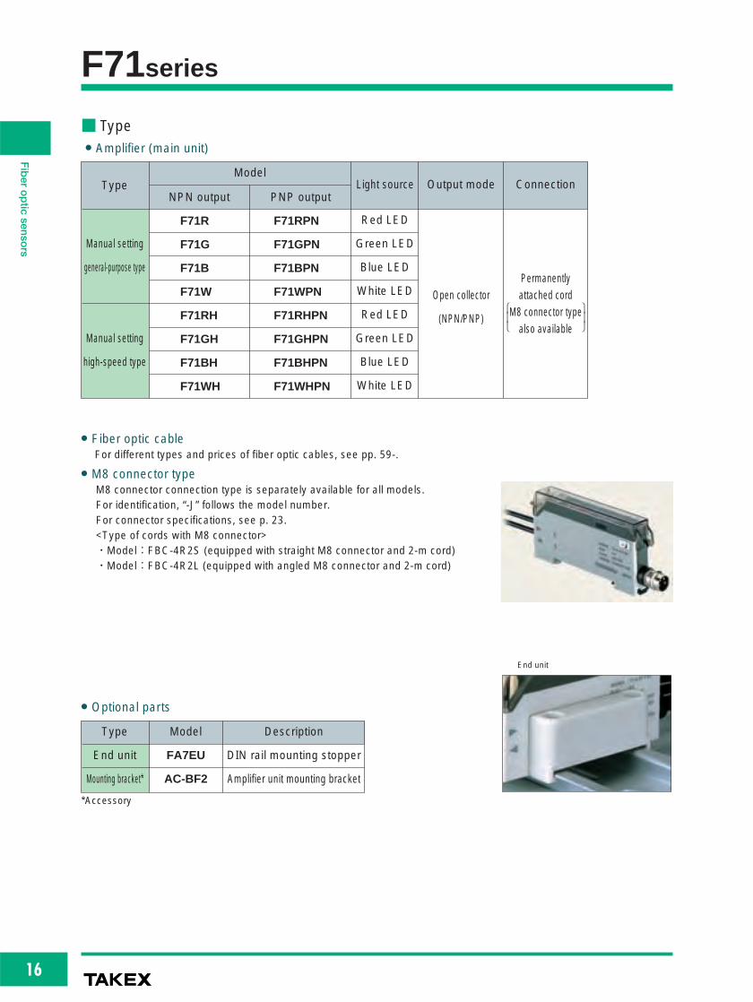
Part names
■ For Correct UseBe sure to follow the instructions in the operation manual provided for correct use of the product.
F71 K8 4
NOR.OFF.D
ON.DD.ON L.ON
+
-SENS.
Indicator for 8 turnsStability indicator
Operationindicator
Sensitivity adjustmentvolume
Light-ON/Dark-ON selector switch
Timer selector switch
Anti Mutual Interference selector switch/Turbomodeselector switch(common) xxxx
(Excluding H type)
F71 HKNOR.OFF D
ON.DD.ON
SENS.L.ON
Indicator for 8 turnsStability indicator
Operationindicator
Sensitivity adjustmentvolume
Light-ON/Dark-ON selector switch
Timer selector switch
SENS. :Sensitivity adjustment volumeL.ON/D.ON :Light-ON (ON when light is received)/Dark-ON
(ON when light is blocked) mode selector switch4/8 (excluding H type) :Anti Mutual Interference selector switch (4: 4
units/8: 8 units)Turbo mode selector switch (4: turbo off/8: turbo on)
NOR/ON.D/ :Timer selector switchOFF.D (Disabled/On delay/Off delay)
Operation indicatorThe orange LED is illuminated when the signal is activated.
Stability indicatorThe green LED is illuminated when the received light level is well above (120% of) the activationlevel. As long as the stability indicator is illuminated when the light is received, the stability of thedetection is ensured without being affected by variation of environment such as ambient temperature.
Anti Mutual Interference/turbo function (excluding H type)The Anti Mutual Interference selector switch doubles with turbo functionselector switch.
Switch set to 8 : The Anti Mutual Interference feature isavailable for up to 8 units and the turbofunction is enabled.
Switch set to 4: The Anti Mutual Interference feature isavailable for up to 4 units and the turbofunction is disabled. The response time is250 μs.
Emissionwindow
ReceptionwindowOpticaltransmissionwindow
Anti MutualInterferenceselector switch
8 4
8 4
Interference may be prevented for up to 4 units(the response time is 250 μs with this setting).
Interference may be prevented for up to 8 units (the response time is 500μs with this setting).
Stability outputThe stability output can be used to check for reduction of the lightintensity level along with any change in the operating environment oroperation over time or to perform initial check of the operation.When four consecutive detections have occurred with the level ofreceived light exceeding the operation level but not reaching 120 percentof the level (range not allowing stable operation), the stability signal isoutput when the control output is deactivated for Light-ON mode. Thestability indicator starts flashing at the same time as the activation of thestability output. If the level of received light gains a margin, the stabilityoutput is deactivated and the stability indicator stops flashing andbecomes illuminated (normal illumination).
Sensitivity adjustment
Reflective type (adjustment for Light-ON mode)①Place the object to be detected in a given position, turn up the
sensitivity adjustment volume (SENS) gradually from Min. and findthe point at which the operation indicator (orange LED) isilluminated (Point A).②Remove the object, turn down the sensitivity adjustment volume
gradually from Max. and find the point at which the operationindicator (orange LED) goes out (Point B). (If the operationindicator is not illuminated even at Max., Max. is regarded as PointB.)③Set the volume at midway between Points A and B.④With the object placed in a given position (light reception state),
make sure that the stability indicator (green LED) is illuminated.
Through-beam type (adjustment for Light-ON mode)①With the object to be detected removed, turn up the sensitivity
adjustment volume (SENS) to Max. and make sure that theoperation indicator (orange LED) and stability indicator (green LED)are illuminated. (If the stability indicator is not illuminated, the setdistance may be too long or the light axis may not be aligned.)②Turn down the sensitivity adjustment volume gradually from Max.
and find the point at which the operation indicator (orange LED)goes out (Point A).③With the object placed in a given position, turn up the sensitivity
adjustment volume gradually and find the point at which theoperation indicator (orange LED) is illuminated (Point B). (If theoperation indicator is not illuminated even at Max., Max. is regardedas Point B.)④Set the volume at midway between Points A and B.⑤With the object removed (light reception state), make sure that the
stability indicator (green LED) is illuminated.
120%100% Activation
level
Controloutput
ON
OFF
Stability output
ON
OFF
Controloutput
ON
OFF
Stability output
ON
OFF
Light-ON
Dark-O
N
+
-SENS.
+
-SENS.
+
-SENS.
Point A = 1 5 Point B = 7 5 Optimum position = 4 5
Anti Mutual Interference
This product is equipped with the Anti MutualInterference feature that takes advantage ofoptical transmission. The optical transmissionsystem uses the transmission windows includingemission and reception windows in the sides ofan amplifier unit as a light path. For this reason,amplifiers must be mounted adjacently on a DINrail so that the transmission windows of adjoiningunits are aligned for secure functioning of theAnti Mutual Interference feature.
Turbo function
Setting the turbo mode selector switch to “8” enables the turbo function.With this function enabled, the response time is increased to 500 μs but thedetecting distance is also increased by about 30% compared with that forthe turbo function disabled (set to “4”).

31
Fiberopticsenso
rs
Detecting distance
35mm
95mm
Detection method
Reflective
Through-beam
Detection method
FR5BC
FT5BC
F71Series
● Detecting distance for -H typeFor high-speed response models, the detecting distance is generallyabout 30% of normal models.
(With turbo function disabled)
Typical example
Use the light shielding sticker (accessory) for grouping amplifiersinto blocks when taking advantage of the Anti MutualInterference features to use more than one sensor. The stickercan also be used when the transmission windows may besubject to strong ambient light. (If the detection allows no mutualinterference, there is no need to use the sticker even if theamplifiers are mounted adjacently.)
8 sensors used (4 units of Block A and 4 units of Block B)
● Apply one light shielding sticker to each of the open transmission windows in thefourth and fifth units.
● After the stickers have been applied, slide one block of units until they come incontact with the other block.
● Note: There may be interference between the two blocks of sensors.
● Apply one light shielding sticker to each of the open transmission windows in theeighth and ninth units.
● After the stickers have been applied, slide one block of units until they come incontact with the other block.
● Note: There may be interference between the two blocks of sensors.
● Apply one light shielding sticker to each of the open transmission windows in the
fourth and fifth units.● After the stickers have been applied, slide one block of units until they come in
contact with the other block.● Note: There may be interference between the two blocks of sensors.
● The 4 units in Block A do notinterfere with each other
Selector switch = 4 (responsetime = 250 μs)
● The 3 units in Block B do notinterfere with each other
Selector switch = 8(response time = 500 μs,turbo function enabled)
● The 4 units in Block B do notinterfere with each otherSelector switch = 4 (response
time = 250μs)
● The 8 units in Block A do notinterfere with each other
Selector switch = 8 (response time = 500 μs, turbofunction enabled)
● The 2 units in Block B do notinterfere with each otherSelector switch = 8
(response time = 500 μs,turbo function enabled)
Example 1
7 sensors used (4 units of Block A and 3 units of Block B)
Example 2
10 sensors used (8 units of Block A and 2 units of Block B)
Example 3
87
65
43
21
Block B
Block A
Light shieldingsticker
● The 4 units in Block A do notinterfere with each otherSelector switch = 4 (response time = 250 μs)
76
5
43
21
Block B
Block A
Light shieldingsticker
Block B
Block A
Light shieldingsticker
4
87 6
5
109
32
1
If the selector switch setting is mixed (both “4” and “8” settings are present)within one block, the Anti Mutual Interference feature does not work. Make surethat the selector switch settings are consistent (either “4” or “8”) within one block.
■ For Correct UseBe sure to follow the instructions in the operation manual provided for correct use of the product.
32
Fiberopticsenso
rs
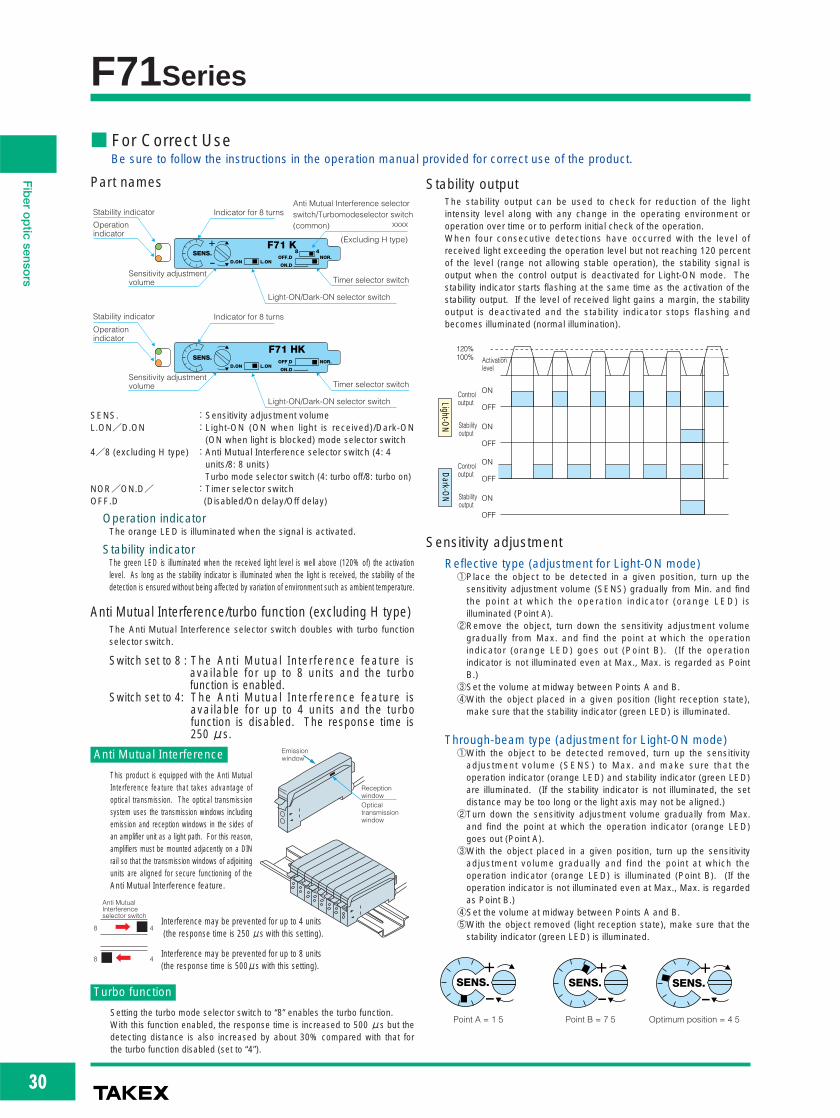
Cord-Connected Type■ Dimensions (in mm)
11
8
M8 connector
AmplifierF70A/F70 SeriesF 71 Series (Common)
M8 connector type
(For dimensions of connector cords, see p. 23.)
Receiver
Transmitter
5
9
9
16
16
21
(21)
11.5 36.5
2-φ3.2×5.2 oval hole
2-φ3.2 hole Mounting bracket
φ4.8 cord (2 m in length)
34.7
4
8
4 60 3
30
For dimensions of fiber optic cables, see pp. 67-.

33
Fiberopticsenso
rs
Simplified-Wiring Connective Type■ Dimensions (in mm)
Receiver
Transmitter
5
9
9
11.5 36.5 10
60
70
30
3
14.5
4.1
4 3
3
9
Amplifier
F70AK/F70K Series
F 71K Series
(Common)
11.5 36.5 10
60
70
30
3
4 3
3
2.5
2
2-4-core cordφ4
2.5
1
Single-core cordφ2.6
With specified connector cord attached
For dimensions of fiber optic cables, see pp. 67-.

34
Fiberopticsenso
rs
Simplified-Wiring Connective Type■ Dimensions (in mm)
3 3
6 5
7.7
13.7
12
2100
2
2.8φ4 cord (2-4-core)
40 10
3 3
6 5
7.7
13.7
12
2100
1
2.8φ2.6 cord (1 core)
40 10
Specified connector cordModel F7K-2Model F7K-3Model F7K-4
Model F7K-1
302-M3×12
40
39
8
17 14
1.9
1.4
1.535.5
32 5
3.2 5.2
16
7
16
23
35
4 7
2.5
4.5
[9]
Mounting bracket (optional)
Model AC-BF2
End unit (optional)
Model FA7EU
(Common to all models)(Provided as accessory for models other than simplified-wiring connective type)

35
Fiberopticsenso
rs

36
Fiberopticsenso
rs
F70TSeriesDigital display Fiber optic sensors
● 2-point “area” output modes
are available
● Inherits advanced functions
of the F70 Series and now
allows a wider range of
detecting conditions
■ Type
Output mode selectable
● 2-point output mode
● Area output (window comparator output) mode
Detection method/detecting distance PNP outputNPN output
ModelOperation mode Light sourceOutput mode
Dependant on fiber opticcable, light source, etc.
F70TRPN
F70TGPN
F70TBPN
F70TWPN
F70TR
F70TG
F70TB
F70TW
Light-ON/Dark-ON
selectable
Red LED
Green LED
Blue LED
White LED
2-pointoutput/area
outputselectable,
open collector
CH1 threshold
CH2 threshold
ON
ON
Output 1
Receivedlight level
Output 2
CH1 threshold
CH2 threshold
ON
ON
Output 1
Receivedlight level
Output 2

37
Fiberopticsenso
rs
Incandescent lamp: 10,000 lx max. / Sunlight: 20,000 lx max.
-25 ~ +55ºC Storage: -40 ~ +70 ºC (non-freezing)
35~85%RH (non-condensing)
10~55 Hz / 1.5 mm amplitude / 2 hours each in 3 direction
500 m/s2 / 3 times each in 3 directions
Fiber optic sensors
■ Environmental Specification
Env
ironm
ent Ambient light
Ambient temperature
Ambient humidity
Vibration
Shock
■ Rating/Performance/Specification
Model
2-point output/area output (window comparator output) selectable
2 open collector outputs
Ch 1: sink current 100 mA (30 VDC max.) / Residual voltage: 1 V or less
Ch 2: sink current 50 mA (30 VDC max.) / Residual voltage: 1 V or less
Ch 1: source current 100 mA (30 VDC max.) / Residual voltage: 2 V or less
Ch 2: source current 50 mA (30 VDC max.) / Residual voltage: 2 V or less
Detection method
Detecting distance
Power supply
Currentconsumption
Control output
Rat
ing
Operation mode
Response time
Accessory
NPN type
PNP type
NPN type
PNP type
NPN type
PNP type
Timer
F70TR
F70TRPN
Red LED
(660nm)
Operation indicator: CH1 = Green LED / CH2 = Orange LED
LCD display with backlight
2 set buttons / Mode selector switch: RUN/SELECT/TEACH
Full auto teaching / Auto teaching
Set button
Provided
Polycarbonate
Permanently attached cord (outer dimension: dia. 4.8) 0.2sq. 4 core 2 m length
Approx. 80 g (including mounting bracket)
Green LED
(525nm)
Blue LED
(470nm)White LED
F70TG
F70TGPN
F70TB
F70TBPN
F70TW
F70TWPNThrough-beam type, reflective type (Dependant on fiber optic cable)
Dependant on fiber optic cable, light source, etc.
12~24V DC ±10% / Ripple 10% max.
39 mA max.
50 mA max.
Light-ON/Dark-ON selectable
On delay/off delay/on-off delay/disabled selectable
Delay time: 40 ms fixed
1 ms max.
Mounting bracket / Operation manual
Rat
ing/
perf
orm
ance
Out
putm
ode
Spe
cific
atio
n
Light source
(wavelength)
Indicator
Display
Switch
Teaching method
Teaching input
Short circuit protection
Material
Connection
Mass
■ For different types and specifications of fiber optic cables, see pp. 59-.

38
Fiberopticsenso
rs
F70T■ Input/Output Circuit and Connection
● NPN output ● PNP output
● Connection
● To extend the cord, use wires of at least 0.3mm2 and limit the length to within 100 m.
Inte
rnal
circ
uit
Brown: 12-24 VDC
White: CH2 OUTPUT
Black: CH1 OUTPUT
Blue: 0V
Inte
rnal
circ
uit
Brown: 12-24 VDC
White: CH2 OUTPUT
Black: CH1 OUTPUT
Blue: OV
Brown: power12-24 VDC
White: CH2 OUTPUT
Black: CH1 OUTPUTMAX 100mA
Blue: OV0V
Load
LoadMAX 50mA
■ Dimensions (in mm)
Receiver
Transmitter
5
9
9
16
16
21
(21)
11 5 36 5
2-φ3 2×5 22 elongate hole
2-φ3 2hole Mounting bracket
φ4 8cord (2 m in leng h)
Cord bushing
34
8
4 60 3
30
4.7

39
Fiberopticsenso
rs
L 1
Channel indication
Example showing indication of Channel 1 information
F70T
LDOF
AT 12S
Operation mode
FunctionA (Area output): Illuminated when the selected output mode is area output. Not illuminated when 2-point output is selected.T (Teaching): Flashes when in the teaching mode.S (Sensitivity adjustment): Indicates that the operation level is being set manually and flashes when sensitivity adjustment is selected.
Receivedlight level Channel indication
The number forthe channel currentlyselected is displayed.
Position on electronic volume
(8-step indication: 1, 2,..., 8)L: Light-OND: Dark-ONO: On delayF: Off delay
Part names Operation
● Selecting operation and output modes
● Channel indicationThe “display” switches between indications for Channels 1 and 2.The LCD channel display indicates the active channel.To switch between channels, with the selector switch at the RUN position,press the set button for the channel to display.
Button 1 for selecting between output modes (2-point/area)
Button 2 for selecting between operation modes
■ For Correct UseBe sure to follow the instructions in the operation manual provided for correct use of the product.
RUNSEL
TEA
2+ -
1
CH 2 set button
CH 1 set button
Output mode selection: selecting between 2-point/area output modes
1. Set the operation selector switch to SEL.
2. Press and hold down Button 1 for 3 seconds or longer thenrelease the button.
3. Pressing Button 1 once (for about 1second) alternates between flashingindications for 1/2 and A.
4. Set the output selector switch back to RUN.
For 2-point output, select the flashing indication for 1/2.
For area output, select the flashing indication for A.
1/2 or A flashes
Operation mode selection: selecting betweenLight-ON/Dark-ON and timer functions
SEL
RUN
RUN
SEL
2 1
2 1
1. Set the operation selector switch to SEL.
2. Press and hold down Button 2 for 3seconds or longer and release the button.
3. Use Button 1 to select the channel to set.
4. Pressing Button 2 once (for about 1 second) switches between the flashing indications for operation modes.
5. Select the operation mode as required and set the operation selector switch back to RUN to complete.
Light-ON
Dark-ON
Off delay
On delay
SEL
SEL
2 1
A 1 2
Channel No. 1 2
L
{ Selection:
LDOF
Output operation
Operation mode indication flashes
Timer operation
TAKEX F70TR
LDOF
AT. 12S
RUNSEL
TEA
2+ -
1
CH 1 operation indicator
CH 2 operation indicator
Green LED
Orange LED
LCD display
Mode selector switch
CH 2 set button
CH 1 set button
LDOF
AT. 12 SEL
2+ -
1
LCD display

40
Fiberopticsenso
rs
Sensitivity setting using moving work: full auto teachingWork positioning setting
Sensitivity setting using stationary work: auto teachingMaximum sensitivity setting: Press the set button twice with the light blocked.
F70T
● Sensitivity setting for 2-point output
■ For Correct UseBe sure to follow the instructions in the provided operation manual for correct use of the product.
1. Set the operation selector switch to TEA. T flashes.
2. Block the light beam with detectable object, this will set the light
blocking state.
3. Press the channel-set button twice, to set the correct channel.
4. Set the operation selector switch back to RUN to complete.
Use of a reflective-type fiber optic cable at the maximum
sensitivity may cause inadequate light blocking. Be sure to
use a work for sensitivity setting.
Example for through-beam type
For reflective type
TEA
1. Set the operation selector switch to TEA. T flashes.
2. Place the detectable object at the desired position.
3. Press the button twice to set the correct channel.
4. Set the operation selector switch back to RUN to complete.
TEA
2 1
Once ! Twice !
2 1
Once ! Twice !
RUN
RUN
Work
1. Set the operation selector switch to TEA. T flashes.
2. With the work in place, press once (for about 1 second) the channel-
set button.
3. Without the detectable object, press once (for about 1 second) the
channel-set button, this will set the correct channel.
4. Set the operation selector switch back to RUN to complete.
TEA
1. Set the operation selector switch to TEA. T flashes.
2. Press and hold down button to set the correct channel.
3. Confirm the indicator is flashing slowly when the work has passed
and then release the set button.
4. Set the operation selector switch back to RUN to complete.
TEA
About 3seconds
Slow flashing
(Set button)Press Release
Let work pass in this period
Flash flash flash flash Flash flash Flash flash Flash flash
RUN
RUN
Work
1
TEA
2 1
1
2
1
2
2 1
Work
2 1
Indicator for the channel to set flashes
Indicator for the channel to set flashes
Let the work pass while holding
down the button.

41
Fiberopticsenso
rs
1. Set the operation selector switc L.
2. Press button once for each channel requiring sensitivity
adjustment.
3. Set the operation selector switch to TEA.
4. Press the “+” or “–” button to adjust the sensitivity (holding
down the button changes the indication faster).
5. When sensitivity adjustment is finished,
set the operation selector switch back
to RUN to complete.
F70T
● Sensitivity setting for area output (a good example would be detecting different levels) ● Sensitivity adjustment: manual adjustment (fine-tuning) of sensitivity
■ For Correct UseBe sure to follow the instructions in the provided operation manual for correct use of the product.
1. Set the operation selector switch to TEA. T flashes.
2. With the detectable object in place for the upper limit, press Button 1
twice (for about 1 second each time).
3. With the detectable object in place for the lower limit, press Button 2
twice (for about 1 second each time).
4. Set the operation selector switch back to RUN to complete.
TEA
TEA
SEL
RUN
RUN
2 1
2 1
Work
Once ! Twic
1
2Flashes and goes out
2 1Work
Once ! Twice !
L T 1
+ - TEA
1
2Flashes and goes out
1
S
Selected channel No. and S flashes.
The value display shows the current
ON level.
Pressing “+” increases the
activation level
= SENS DOWN
Pressing “–” decreases the
activation level
= SENS UP

42
Fiberopticsenso
rs
F70VSeriesPreset counter-equippedFiber optic sensors
● Equipped with two preset
up/down counter circuits
● Sensor on/off output and
preset counter output are
provided
■ TypeDetection method/detecting distance PNP outputNPN output
ModelOperation mode Light sourceOutput mode
Dependant on fiber opticcable.
F70VRPNF70VRLight-ON/Dark-ON selectable
Red LED2 open
collectoroutputs
Counts the number of sensor activations/deactivations and outputs a one-shot
signal when the count has reached the predefined setting (preset value).
The green indicator is illuminated while the one-shot signal is output.
The preset counter has the following three modes:
■ About Preset Counter
■ Application example
Wide area fiber optic cable used for wide-view detection.Outputs a signal when the predefined number of falling workshas been counted, eliminating the need for a separatecounter unit.
Counting worksSensor
Sensor
P-1 mode (factory setting)
Preset counter VOUT1
OUT2
OUT1
OUT2
OUT1
OUT2
P-
P-2 modeP-
P-3 modeP-
Preset counter V1
Preset counter V2
Preset counter V1
Preset counter V2
Sensor

43
Fiberopticsenso
rs
Incandescent lamp: 10,000 lx max. / Sunlight: 20,000 lx max.
–25 ~ +55 ºC Storage: –40 ~ +70 ºC (non-freezing)
35~85%RH (non-condensing)
10~55 Hz / 1.5 mm amplitude / 2 hours each in 3 direction
500 m/s2 / 3 times each in 3 directions
Fiber optic sensors
■ Environmental Specification
Env
ironm
ent Ambient light
Ambient temperature
Ambient humidity
Vibration
Shock
■ Rating/Performance/SpecificationType
Model
2 open collector outputs
OUT 1: sink current 100 mA (30 VDC max.)
OUT 2: sink current 50 mA (30 VDC max.)
Residual voltage: 1 V or less
OUT 1: source current 100 mA (30 VDC max.)
OUT 2: source current 50 mA (30 VDC max.)
Residual voltage: 1 V or less
Detection method
Detecting distance
Power supply
Current consumption
Control output
Output mode
Operation mode
Response time
Accessory
Timer
NPN output type
F70VR
Red LED (660nm)
Operation indicator: OUT 1 = Orange LED / OUT2 = Green LED
LCD display with backlight
Single preset counter: 1 mode / Double preset counter: 2 modes
One-shot signal
Selectable between 50 ms, 100 ms, 200 ms, 500 ms and 1 s (factory setting: 100 ms)
Variable between 2 and 9999
2 set buttons / Mode selector switch: RUN/SELECT/SET
Full auto teaching / Auto teaching
Set button
Provided
Polycarbonate
Permanently attached cord (outer dimension: dia. 4.8) 0.2sq. 4 core 2 m length
Approx. 80 g (including mounting bracket)
PNP output type
F70VRPNThrough-beam type, reflective type
(Dependant on fiber optic cable)
12~24V DC ±10% / Ripple 10% max.
39 mA max. 50 mA max.
Light-ON/Dark-ON selectable
On delay/off delay/on-off delay/disabled selectable
Delay time: 40 ms fixed
1 ms max.
Mounting bracket / Operation manual
Rat
ing/
perf
orm
ance
Spe
cific
atio
n
Light source (wavelength)
Indicator
Display
Preset counter
Output
Output signal length
Counter setting
Switch
Teaching method
Teaching input
Short circuit protection
Material
Connection
Mass
■ For different types and specifications of fiber optic cables, see pp. 59-.

44
Fiberopticsenso
rs
F70V■ Input/Output Circuit and Connection
● NPN output ● PNP output
● Connection
● To extend the cord, use wires of at least 0.3mm2 and limit the length to within 100 m.
Inte
rnal
circ
uit
Brown: 12-24 VDC
White: OUTPUT2
Black: OUTPUT1
Blue: 0V
Inte
rnal
circ
uit
Brown: 12-24 VDC
White: OUTPUT2
Black: OUTPUT1
Blue: 0V
Brown: power12-24 VDC
White: OUTPUT2
Black: OUTPUT1MAX 100mA
Blue: 0V0V
Load
LoadMAX 50mA
■ Dimensions (in mm)
Receiver
Transmitter
5
9
9
16
16
21
(21)
11 5 36 5
2-φ3 2×5.2elongate hole
2-φ3 2hole Mounting bracket
φ4 8cord (2 m in length)
Cord bushing
34
8
4 60 3
30
4.7

45
Fiberopticsenso
rs
F70V
LDOF
T 12S V
Operation mode
Function
V: Illuminated when the preset counter value is displayed.T (Teaching): Flashes when in the teaching mode.S (Sensitivity adjustment): Indicates that the operation level is being set manually and flashes when
Received light level Preset counterchannel indication
Position on electronic volume
(8-step indication: 1, 2,..., 8)L: Light-OND: Dark-ONO: On delayF: Off delay
Part names ● Operation and setting mode selection
● Overview of operation
● Switching between indicationsThe display switches between indications for received light level andpreset counter value.To switch between indications, with the selector switch at the RUNposition, press the black button.
Press red button to select between setting modes (teaching/sensitivitysetting/preset counter setting)
Press black button to select between operation modes
■ For Correct UseBe sure to follow the instructions in the operation manual provided for correct use of the product.
Black button: Switches between indications
Red button: Switches between preset count-up and count-down displays.
Black button: Switches between operation modes including Light-ON, Dark-ON and timer functions.
Red button: Selects between operation modes.
Operation mode
T: Teaching
S: Sensitivity setting
V, V1, V2: Preset value setting
Teaching: Press the red button for teaching.
Increase/decrease the sensitivity.
View/set the preset value.
T
S
V
SET
L L 1V
L 1V
L 1V
SEL
RUN
TAKEX F70VR
LDOF
T. 12S V
RUNSEL
TEA
+ -
Counter output indicator
Sensor light reception indicator
Green LED
Orange LED
LCD display
Mode selector switch
Black set button
Red set button
LDOF 2V SEL
+ -
LCD display
L L 1V
Position on the electronic volume
Received light level
Operation mode (L: Light-ON)Count
Count-up/down indication
Preset counter channel (count for V1 shown)
Received light indication Preset counter value indication

46
Fiberopticsenso
rs
● Ultra-slim 9-mm body
● 8-turn adjustment with
indicator for fine-tuning
● Red LED allows for
checking of illumination
■ TypeType /
Detection method
Fiber typeThrough-beam
Reflective(Dependant on
fiber opticcable)
Dependant on fiber opticcable, light source, etc.
Detecting distance Model Operation mode Output mode
F71RAN
Voltage output inproportion toreceived light
intensity
Effective voltagerange: 2~8 V
■ Application example
Comparative detection ofthickness of paper, etc.
Liquid level detection Loop control
(ANP Series)
(See P. 612 for details)
● Applicable comparator● “White LED” is used for light emitting elementA model that uses white LED as the light emitting elementis available separately.Model.: F71WAN
Analog sensor
Output
Comparator
Sample paper
Target paper
Analog sensor
Output
Comparator
Liquid
Sheet material
Loop
Analog sensor
F71RANSeriesAnalog outputFiber optic sensors

47
Fiberopticsenso
rs
F71RAN■ Rating/Performance/Specification
■ Environmental Specification
■ Detecting Distance with Different Fiber Optic Cables (Typical Example)
■ Input/Output Circuit and Connection
■ Dimensions (in mm)
Model
Detection method
Power supply
Current consumption
Output mode
Operation mode
Response time
Temperature drift
Output ripple
Rat
ing/
perf
orm
ance
Spe
cific
atio
n
Light source (light wavelength)
Indicator
Case material
Connection
Mass
* The range may be 1~9 V depending on the characteristics of theindividual products and fiber optic cables.
For specifications, dimensions, etc. of fiber optic cables, see pp. 59-.
F71RAN
Fiber type
12~24 VDC ± 5 % / Ripple: 2% max.
30 mA max.
Effective voltage range: 2~8 V (NPN emitter follower)*
Voltage output in proportion to received light intensity (current 3 mA max.)
Rise from 2 to 8 V in 10 ms max.
Fall from 8 to 2 V in 25 ms max.
0.3%/ ºC max. at –10 ~ +50 ºC
80 mV max.
Red LED (680 nm)
Power (green) / Light intensity (orange)
Case: heat-resistant ABS / Cover: polycarbonate
Permanently attached cord (outer dimension: dia. 4.8) 0.2sq. 3 core 2 m length
Approx.90 g (including 2-m cord and mounting bracket)
Ambient lightAmbient temperatureAmbient humidityProtective structure
VibrationEnv
ironm
ent
Detection method
Through-beam
Fiber optic cable model Detecting distance (mm)
120㎜
30㎜
8㎜
70㎜
80㎜
10㎜
60㎜
FT105BC
FT8EBC
FT5YBC
FTS5BC
FTSV73BC
FTL716BC
GTH520J
Incandescent lamp: 10,000 lx max.–25 ~ +55 ºC (non-freezing)
35~85%RH (non-condensing)IP40
10~55 Hz / 1.5 mm amplitude / 2 hours each in 3 direction
Inte
rnal
circ
uit
Brown: 12-24 VDC
Black: analog voltage output *1
Lead color
*1: Output current: 3 mA Effective voltage range: 2~8 V
Blue: 0V
Receiver
Transmitter
5
9
9
16
16
21
(21)
11 5 36 5
2-φ3.2×5.22 elongate hole
2-φ3.2hole Mounting bracket
φ4.8co d (2 m in length)
Cord bushing
34
8
4 60 3
30
4.7
Detection method Fiber optic cable model Detecting distance (mm)
50㎜
30㎜
10㎜
3㎜
20㎜
8㎜
10㎜
FR105BC
FR108BC
FXN84BC
FRS8BC
FRL732BC
FRSV55BC
GXH520J
ReflectiveDetection
object: 50mm□
white non-gloss paper

48
Fiberopticsenso
rs
F71RAN■ Distance-Output Characteristics (Typical Example) with F71RAN + Different Fiber Optic Cables (50 mm□white non-gloss paper used as detection object for reflective types)
FT105BC(through-beam)
9
8
7
6
5
4
3
2
1
20 40 60 80 100120 140160180Distance (mm)
Out
put
vol
tag
e (V
)
FT8EBC(through-beam)
9
8
7
6
5
4
3
2
1
5 10 15 20 25 30 35 40 45Distance (mm)
Out
put
vol
tag
e (V
)
FT5YBC(through-beam)
11
10
9
6
7
8
5
4
3
2
1
2 4 6 8 10Distance (mm)
Out
put
vol
tag
e (V
)
FTS5BC(through-beam)
10
9
7
8
6
5
4
3
2
1
10 20 30 40 50 60 70 80 90 100Distance (mm)
Out
put
vol
tag
e (V
)
FTSV73BC(through-beam)
10
9
7
8
6
5
4
3
2
1
10 20 30 40 50 60 70 80 90 100Distance (mm)
Out
put
vol
tag
e (V
)
FTL716BC(through-beam)
9
6
7
8
5
4
3
2
1
2 4 6 8 10 12 14Distance (mm)
Out
put
vol
tag
e (V
)
GTH520J(through-beam)
9
8
7
6
5
4
3
2
1
10 20 30 40 50 60 70 80 90Distance (mm)
Out
put
vol
tag
e (V
)
FR105BC(reflective)
9
6
7
8
5
4
3
2
1
10 20 30 40 50 60 70Distance (mm)
Out
put
vol
tag
e (V
)
FR108BC(reflective)
9
6
7
8
5
4
3
2
1
5 10 15 20 25 30 35Distance (mm)
Out
put
vol
tag
e (V
)
FXN84BC(reflective)
9
6
7
8
5
4
3
2
1
2 4 6 8 10 12 14Distance (mm)
Out
put
vol
tag
e (V
)
FRL732BC(reflective)
11
10
6
7
8
9
5
4
3
2
1
Distance (mm)
Out
put
vol
tag
e (V
)
5 10 15 20 25
FRSV55BC(reflective)
11
10
6
7
8
9
5
4
3
2
1
Distance (mm)
Out
put
vol
tag
e (V
)
2 4 6 8 10
GXH520J(reflective)
9
8
7
6
5
4
3
2
1
Distance (mm)
Out
put
vol
tag
e (V
)
2 4 6 8 10 12 14 16 18
FRS8BC(reflective)
9
6
7
8
5
4
3
2
1
1 2 3 4Distance (mm)
Out
put
vol
tag
e (V
)

49
Fiberopticsenso
rs
F71RAN■ Temperature Characteristics (Typical Example)
■ For Correct Use● Do not use sensor outdoors or in a place subject to a
direct disturbing light surface.● Analog voltage takes about 30 minutes to stabilize
after power-up. For detections requiring accuracy,supply power well in advance. Fluctuations of about100 mV should be expected.
9
8
7
6
5
4
3
2
1
0ー20ー10 0 10 20 30 40 50 60 70
Temperature (°C)
Out
put
vol
tag
e (V
)
high
medium
low
The graph shows characteristics based on
temperature variations for high,
medium and low output voltage settings with the
same detecting position.

50
Fiberopticsenso
rs
F2RSeries
● Amazingly slim size(8 x 10 x 73 mm)
● Low cost●NPN and PNP output types are
available●High-speed response of 500μs
● Good Design Selection
● Two types of connections available: 1) permanently attached cord and 2) quick release connector
● Flexible mounting
● Adapter for small-diameter fiber optic
cables ● Also allows mounting with zip-tie bands
● Comes with a DIN rail (35 mm) mounting
bracket (screw-mounting also available)
● Connector type (DIN compatible) available
for single-touch replacement of amplifier
Extra slim size achieves a narrow appearance and provides ease of use
73.7
10
Fiber optic sensors

51
Fiberopticsenso
rs
F2R
■ Rating/Performance/Specification
Model
Detection method
Detecting distance
Power supply
Current consumption
Output mode
Operation mode
Response time
Hysteresis
Type NPN output type PNP output type
F2R F2R-J(Note) F2RPN F2RPN-J(Note)
Through-beam type, reflective type (Dependant on fiber optic cable)
Dependant on fiber optic cable
12~24V DC ±10% / Ripple 10% max.
25mA max.
NPN open collector outputRating: sink current 100 mA (30 VDC max.)
PNP open collector output
Rating: source current 100 mA max.
Rat
ing/
perf
orm
ance
Spe
cific
atio
n
Light source (wavelength)
Indicator
Volume (VR)
Switch (SW)
Short circuit protection
Case Material
Connection
Mass
Accessory
Light-ON/Dark-ON selectable(with selector switch)
500 ms max.
Up to 10% of detecting distance
Red LED (660nm)
SENS : Sensitivity adjustment volume provided
OP.L: operation indicator (red LED)STB: stability indicator (green LED)
Light-ON/Dark-ON selector switch; L: Light-ON/D: Dark-ON
Provided
Noryl (filler: styrene elastomer)
Permanently attached cord(outer dimension: dia. 3.5)0.2sq. 3 core 2 m length
Approx. 40 g
Screwdriver for operating sensitivity adjustment volume and Light-ON/Dark-ON switch, DIN rail mounting bracket (material: polycarbonate)
Approx. 65 g Approx. 40 g Approx. 65 g
Connector type cord with connectorseparately available
Permanently attached cord(outer dimension: dia. 3.5)0.2sq. 3 core 2 m length
Connector typecord with connectorseparately available
■ Type
■ For different types of fiber optic cables, see pp. 59-.
Detection method/detecting distance Model Light source Operation mode Output mode Remarks
Dependant on fiber optic cable.
F2R
F2R-J
F2RPN
F2RPN-J
Red LED
Light-ON/Dark-ON
selectable with selector
switch
NPN opencollector
PNP opencollector
Connector type
Connector type
■ Environmental Specification
Env
ironm
ent Ambient light
Ambient temperature
Ambient humidity
Protective structure
Vibration
3,000 lx max.
–25 ~ +55 °C (non-freezing)
35~85%RH (non-condensing)
IP65
10~55 Hz / 1.5 mm amplitude / 2 hours each in 3 direction
Type
NPN type
PNP typeMod
el
Amplifier only
F2R-J
F2RPN-J
Amplifier andcord withconnector
F2R-JC3
F2RPN-JC3
Cord withconnector
only
F2-C3
《Connector type models》
The cord with connector contains 0.2sq. 3 core 2.5 m length
● Connector-type set models F2R-JC3 and F2RPN-JC3 come with a cord
with connector model F2-C3.● For details, see “Connector type models” below.

52
Fiberopticsenso
rs
F2R■ Input/Output Circuit and Connection
■ Operation Mode Switching
■ About Indicators
● NPN output ● PNP output
● Connector type (-J) pin assignment
● The operation indicator (red LED) and stability indicator (green LED) show the light intensity levels described in thefigure below.
● After light axis and sensitivity adjustments have been completed, repeat activation and deactivation by placing andremoving the detectable object to make sure that the sensitivity is with in the stable activation/deactivation range.
● Setting within the stable range increases reliability against variations in the environment after setting.
The output transistor turns off when load short circuit or overload occurs. Check the load and turn the power back on.
Light-ON Dark-ON
For Light-ON mode: Set the switch to L (Light).For Dark-ON mode: Set the switch to D (Dark)
Inte
rnal
circ
uit
Indicator
Blue: 0V
Black: Output
Brown: 12-24 VDC
Lead color
Inte
rnal
circ
uit
Indicator
Blue: 0V
Black: Output
Brown: 12-24 VDC
Lead color
Output (black)
0V (blue)
Side showing indicators
12-24 VDC(brown)
D L D L
Illuminated Illuminated
Illuminated
Illuminated
Stable activation range Stable deactivation range
Activation level Activation level Activation level×1.2 ×0.8
Light-ON modeDark-ON mode
Green LED…………
Red LED

53
Fiberopticsenso
rs
F2R■ Dimensions (in mm)
● Loosen the upper screw and insert a fiber optic cable. The insertion may feel stiff at some point, which is due to thepacking material the fiber optic cable needs to pass through. Be sure to insert all the way until it stops and then tightenthe screw. The tightening torque should not exceed 0.3 N・m.
● When using a small-diameter fiber optic cable, attach the provided adapter first.
Attaching fiber optic cables
F2R, F2R-PN (permanently attached cord) F2R-J, F2RPN-J (connector type)
8.2
5.2
60.7
11 20 3 6.4 8
13
φ3.5
10
7.2Fiber optic
cable R OP.L SENSG STB.
4.3
8.2
2-φ2 2 Light-ON/Dark- ON selector switch Cord (2 m)
8.2
5.2
60.7
11 20.3 6.4 8 5
30
φ3.5
10
7 2Fiber optic
cable R
A
OP.L SENSG STB.
4 38 2
2-φ2.2Light-ON/Dark- ON selector switch
Cord (2 m)
5
PlugReceptacle
Detail of A
14 Pitch
30
4-M3 tap
(With separately available cord with connector model F2-C3 attached)
● With DIN rail mounting bracket attached
● Pitch for adjacent screw mounting (14 mm)
56
13.5
(7 5) (10.5)
R OP.L SENS.G STB.
Fiber optic cable
Light-ON/Dark- ON selector switch Cord (2 m)
56
13 5
(7.5)(27.5)
R OP.L SENS.G STB.
Fiber optic cable Light-ON/Dark- ON
selector switch
ACord (2 m)
16
13 5 30 2-φ3.2 mounting hole
Compatible w th35-mm DIN rail

54
Fiberopticsenso
rs
FLD1RSeries
● Employs red semiconductor laser (class 2)
● Visible small spot allows confirmation ofdetecting position
● Small object of 0.1 mm can be detected
● Ideal for detecting end of thin objectsuch as wafer mapping, etc.
● Light emission stop function isconvenient as a safety measure andinspection at start of operation
■ TypeDetectionmethod Detecting distance Model Operation
modeLight source Output mode
Reflective20~120㎜
AmplifierFLD1R
Fiber optic cableFR720LD
Light-ON/Dark-ON
selectable
Redsemiconductorlaser (class 2)
NPN, PNPopen collector
■ Applications
Reflective type fiber optic cable
Take safety measures accordingto the operation manual
■ Directional Characteristics (Typical Example)
5 5
20
50
100
B: White drawing paper detection point
B: White drawing paper detection point
A: White drawing paper detection point
150
170
200 φ9.5
φ7.5
φ6
φ4.5
φ3.2
φ4
73 30
Transmittedlight axis
Received light axis
Light spot pattern(diameter in mm)
Direction of movement of object
A: White drawing paper detection point
Wafer detectionCarrier movement is controlled by the detection ofwafers.The small spot of the laser beam achieves reliabledetection.
Laser typeFiber optic sensors

55
Fiberopticsenso
rs
FLD1R
■ Dimensions (in mm)
■ Input/Output Circuit and Connection
■ For Correct Use
Amplifier
Fiber optic cableModel
Type
Detecting distance
Spot diameter
Smallest allowable detection object
Allowable bending radius
Fiber optic cable length
Material
Applicable amplifier
Mass
FR720LD
Reflective type
20 ~ 120mm
Aboutφ5 (at distance of 100 mm)
φ0.1 (Detecting distance: 30~60 mm / Sample: copper wire)
R30
2 m (uncuttable)
Plastic fiber optic cable (polyethylene-covered)
FLD1R
About 45 g
● Slow starting is employed for laser emission and illumination
can be confirmed about 0.5 seconds after power-up or
emission stop reset.● The output transistor turns off when the load short circuits or
an overload occurs.
Eliminate any short circuit or overload state and then turn the
power back on for reset● Short-circuiting the pink and blue leads (no-voltage contact or
NPN open collector) stops the laser beam.
● The semiconductor laser falls under Class 2 as defined in JIS
C 6802 “Safety of Laser Products.” Never look straight into
the illuminated laser beam, which may damage the eye. This
laser does not affect human skin.● Use correctly and safely according to the operation manual
provided.
■ Rating/Performance/Specification
Model
Power supply
Current consumption
Output mode
Operation mode
Laser light emission
stop input
Response time
Light source
Indicator
Volume
Switch
Short circuit protection
Material
Connection
Mass
Type Laser type fiber optic sensor
FLD1R12~24 VDC ± 10 % / Ripple: 10% max.
38 mANPN/PNP open collector
100 mA (30 VDC) max.
Light-ON/Dark-ON selectable
Closed: stopped / Open: emitted / Contact:
open collector input (Closed: L = 1 V max.)
0.5 ms max.
Red semiconductor laser (650 nm) class 2
OP.L: operation indicator (red) /
STB: stability indicator (green)
Sensitivity adjustment volume provided (8-turn without stopper)
Light-ON/Dark-ON selector switch provided
Provided
Case: heat-resistant ABS /
Cover: polycarbonate
Permanently attached cord (outer dimension:
dia. 4.5) 0.2sq. 5 core 2 m length
Approx. 90 g (including cord and mounting bracket)
■ For Correct UseAmbient light
Ambient temperature
Ambient humidity
Protective structure
Vibration
3,000 lx max.
–10 - +40 °C (non-freezing)
35-85%RH (non-condensing)
IP 66 (with protective cover attached)
10-55 Hz / 1.5 mm amplitude / 3 times each in 3 direction
Amplifier Fiber optic cable
Rat
ing/
perf
orm
ance
Spe
cific
atio
n
Inte
rnal
circ
uit
Brown: 12-24 VDC
Black: NPN outputWhite: PNP output
Blue: 0V
Pink: Test input: laser emission stop input (emission stop 1 V max.)
99
9 4 456
47
1621.2
35 3
3
135
32
4
4 5
6.717
Cordφ4.5
2-φ3.2×3.6 elongate hole
2-φ3 2×3 6 elongate hole
13
12
34
13 5
Transmitter
Receiver
22
2000
15 102-φ3 2
φ2
2
φ2
2
φ3
14
30
7 4
14
AL Black coloring
7
3
7
+
+
Transmitter
Receiver
Bsbm

56
Fiberopticsenso
rs
F10R-ATA high-performance pulse
amplification method is used
for the detection of minor
changes
● The light intensity reference point is
automatically captured and stored for
simple sensitivity adjustment
● Visible red LED light spot
This sensor detects slight changes in light intensity generated by object movement with in the detection area.
For this reason, only a moving object can be detected even if a stationary object (fixed object in the
background) and a moving detection object are on the same mirror-like material such as a stainless-steel
plate or stationary and moving objects are of the same color.
● Detection of fallingminute objects such aschip components
● Detecting the passage oftransparent containers
● Detecting objects of the samematerial as background
● Detecting the passageof register marks
● Detection of minute objectspassing with in a large area (without background influence)
■ Type
■ Applications
Detectionmethod Detecting distance Model Operation modeLight source Output mode
Through-beam
Reflective(Dependant
on fiberoptic cable)
Dependant on fiberoptic cable
F10R-AT
・Light-ON/ Dark-ON selectable・Timer mode
selectable(With switch)
Red LEDNPN
open collector
● Detection of ruled lines ● Checking the number ofcopies of booklets,catalogs, etc.
● Detecting the number ofrotations
● Detecting the passing ofpins without influence ofbackground
● Detection of passage ofconcave portions
Stationary object (stainless steel)
響はありません
■ For different models and specifications of fiber optic cables, see pp. 59-.
Fiber optic sensors

57
Fiberopticsenso
rs
■ Input/Output Circuit and Connection ■ Dimensions (in mm)
The output transistor turns off when load
short circuit or overload occurs.
Check the load and turn the power back on.
Inte
rnal
circ
uit
Indicator
Blue: 0V
Black: Output
Brown: 12-24 VDC
Lead color
Ambient light
Ambient temperature
Ambient humidity
Protective structure
Vibration
Incandescent lamp: 10,000 lx max./ Sunlight: 20,000 lx max.
–25 ~ +55 °C (non-freezing)
35~85%RH (non-condensing)
IP 66 (with protective cover attached)
10~55 Hz / 1.5 mm amplitude / 2 hours each in 3 direction
■ Rating/Performance/Specification
■ Environmental Specification
Rat
ing/
perf
orm
ance
Spe
cific
atio
nE
nviro
nmen
t
Type
Model
Detection method
Power supply
Current consumption
Output mode
Operation mode
Response time
Minimum moving speed
Light source (wavelength)
Indicator
Volume (VR)
Switch (SW)
Short circuit protection
Case material
Connection
Mass
Pulse amplification type fiber optic sensor
F10R-ATThrough-beam type, reflective type (Dependant on fiber optic cable)
12~24V DC ±10% / Ripple 10% max.
40mA max.
NPN open collector output
Rating: 100 mA, 30 V max.
Light-ON/Dark-ON selectableTimer mode selectable (With switch)
0.5ms max.
0.5 Hz min.
Red LED (660nm)
LIGHT: light reception indicator (green LED)
O.P: operation indicator (red LED)
Sensitivity adjustment volume provided
Light-ON/Dark-ON selector switch/timer selector switch provided
Provided
Case: heat-resistant ABS / Cover: polycarbonate
Permanently attached cord (outer dimension: dia. 4.5) 0.2sq. 3 core 2 m length
Approx. 90 g (including cord and mounting bracket)
F10R-AT
99
9 4 456
47
1621 2
35 3
3
135
32
4
4 5
6.717
Cord φ4.5
2-φ3.2×3 6elongate hole
2-φ3.2×3.6elongate hole
13
12
34
13 5
Transmitte
Receiver

58
Fiberopticsenso
rs

Fiber
Optic
Cables
59
Fiber Optic Cables

60
FiberOpticCables
Fiber Optic Cables
Type
Long-distance
Flexible
Narrow-view
SUS tube
General-
purpose
Lens-integrated
Tip appearance
(typical)Model No.
(made-to-order modelsmarked with ●)
1800 1000 1000 600 160
2000 1100 1100 660 120
470 260 260 150 60
230 130 130 75 30
860 480 480 280 100
830 460 460 270 80
830 460 460 270 80
230 130 130 75 30
830 460 460 270 80
830 460 460 270 80
830 460 460 270 80
470 260 260 160 50
180 100 100 60 20
135 75 75 48 15
- - - - 60
700 380 380 230 70
2300 1300 1300 750 350
2200 1200 1200 720 300
2200 1200 1200 720 300
230 130 130 75 30
230 130 130 75 30
230 130 130 75 30
230 130 130 75 30
130 70 70 40 15
20 10 8 4 -
440 240 240 140 40
40 20 19 11 -
130 70 70 40 15
500 280 280 160 60
M4 screw, detectinglong-distance
Long-distance with lens
M3 screw, low-cost
M3 screw, small-diameter
M3 threaded short head
M4 screw
M4 screw with M2.6screw tip
φ1.5 unthreaded
φ2.9 unthreaded
φ4 unthreaded
M5 screw
4-mm square head
φ1.5 unthreaded, allowablebending radius 4 mmM3 screw, allowablebending radius 1 mmM3 screw, allowablebending radius 3.5 mmM4 screw, allowablebending radius 1 mm
M4 screw, long-distance
φ4 unthreaded, long-distance
4-mm square head
M3 screw, SUS 15 mm
M4 screw, SUS 35 mm
M3 screw, SUS 70 mm
M4 screw, SUS 70 mm
φ2 unthreaded, SUS 20 mm
φ2 unthreaded, SUS 20 mm
φ3 unthreaded, SUS 20 mm
φ3 unthreaded, SUS 20 mm
M4 screw, SUS 20 mm
M4 screw, SUS 65 mm
1
2
3
4
5
6
7
8
9
10
11
12
13
14
15
16
17
18
19
20
21
22
23
24
25
26
27
28
29
FT105BC
FT7202BC
FT8EBC
FT8BC
FT108BC
FT5BC
FT7BC
FT81BC
FT3BC
FTV74BC
FTV7BC
FTV502YBC●
FT91YBC●
FT19YBC
GTKシリーズ
FT5YBC
FTN5BC
FTVN5BC
FTVN501BC
FTS88BC
FTS53BC
FTS8BC
FTS5BC
FTSV82BC
FTSV821BC●
FTSV73BC
FTSV93BC
FTSV84BC●
FTSV5BC
SearchIDNo.
Prominent feature
Detecting distance (mm) (inapplicable combinations marked with-)
Long-distance
F80RHigh-speed
F70RF70AR F71R F2R
Identify models by numbers for search (for specifications, dimensions, etc.)Through-Beam type
Side-view
Side-view
Side-view
61
FiberOpticCables
Fiber Optic Cables
Type
U-shaped
Wide area
Elbow
Heat-resistant
Tip appearance
(typical)Model No.
(made-to-order modelsmarked with ●)
7
12
15
25
12
30
300 170 170 95 30
680 380 380 220 80
680 380 380 220 80
680 380 380 220 80
540 300 300 180 60
680 380 380 220 80
1800 1000 1000 - -
680 380 380 220 80
12
830 460 460 270 80
610 340 340 195 -
610 340 340 195 -
610 340 340 195 -
830 460 460 270 80
No light axis alignment required
Vibration-resistant
4 light axes
16 light axes
Detecting width 1.75 mm
Detecting width 5.5 mm
Detecting width 11.1 mm
Detecting width 16 mm
Detecting width 45 mm
Detecting width 5.5 mm
Long-distance with detecting width 10 mmDepth space saving withφ2.5U-shaped, heatresistance 130 ºCLow-cost, heatresistance 105 ºCM4 screw, heatresistance 200 ºCM4 screw, heatresistance 200 ºCM4 screw, heatresistance 350 ºCLow-cost, heatresistance 105 ºC
30
31
32
33
34
35
36
37
38
39
40
41
42
43
44
45
46
47
48
49
FU505BC
FU712BC
FU715BC
FU725BC●
FU904BC●
FU916BC●
FTL706BC
FTL716BC
FTL7165BC
FTL7166BC●
FTL745BC●
FTLV702BC●
FTVW7YBC
FT704BC
FUH612BC●
FTH7BC
GLT500J series
GT500J series
GTH500J series
FTHV74BC●
SearchIDNo.
Prominent feature
Detecting distance (mm) (inapplicable combinations marked with-)
Identify models by numbers for search (for specifications, dimensions, etc.)Through-Beam type
●Detecting distance depends on light sourceDetecting distances depend on the type of light source.
The detecting distances for individual fiber optic cable models in the table above show the values for combinations with
amplifiers using red (R) LED as the light source. Detecting distances for combinations with amplifiers using green (G),
blue (B) or white (W) LEDs as the light sources are reduced to about 30%.
Side-view
Side-view
Long-distance
F80RHigh-speed
F70RF70AR F71R F2R

62
FiberOpticCables
Fiber Optic Cables
Type
Long-distance
Tip appearance
(typical)Model No.
(made-to-order modelsmarked with ●)
570 320 320 190 50
90 50 50 30 9
360 200 200 120 40
190 110 110 65 20
190 110 110 65 20
90 50 50 30 9
90 50 50 30 9
360 200 200 120 40
320 180 180 100 35
320 180 180 100 35
40 20 20 12 4
60 30 30 18 6
40 20 13 8 3
20 10 10 6 2
60 30 30 16 7
40 20 13 8 3
220 120 120 70 25
220 120 120 70 25
- - - - 20
40 22 22 13 5
12 6 5.5 3 -
-
M6 screw, long-distance
φ3 unthreaded, small-diameter
φ3 unthreaded
φ3 unthreaded short head
M3 screw, low-cost
M3 screw, small-diameter
M4 screw, small-diameter
M4 screw
φ2.5mm head, M6 screw
M6 screw, long-distance detection
φ1.5 unthreaded, allowablebending radius 4 mmφ3 unthreaded short head,allowable bending radius 4 mmM3 screw, allowablebending radius 1 mmM3 screw, allowablebending radius 4 mmM4 screw, allowablebending radius 4 mmM4 screw, allowablebending radius 1 mmM6, 1 mm-pitch screw,allowable bending radius 1 mmM6, 0.75 mm-pitch screw,allowable bending radius 1 mmM6 screw, allowablebending radius 3.5 mmM4 screw, coaxialnarrow-viewM4 screw, coaxial narrow-view with φ1.5 spotNarrow-view, angle ofaperture 10 degrees
50
51
52
53
54
55
56
57
58
59
60
61
62
63
64
65
66
67
68
69
70
71
FR105BC
FR83BC
FR1083BC
FR835BC●
FR8EBC
FR8BC
FR84BC
FR108BC
FR7BC
FR5BC
FR91Y10
FR93BC
FR19YBC
FR8YBC
FR84YBC●
FR194YBC●
FR5YBC
FR7YBC
GXKシリーズ
FXN84BC
FXN841BC
FR707BC●
SearchIDNo.
Prominent feature
Identify models by numbers for search (for specifications, dimensions, etc.)Reflective Type
General-
purpose
Flexible
Narrow
-view
Coaxial
Extra narrow-view
●Detecting distance depends on light sourceDetecting distances depend on the type of light source.
The detecting distances for individual fiber optic cable models in the table above show the values for combinations with
amplifiers using red (R) LED as the light source. Detecting distances for combinations with amplifiers using green (G),
blue (B) or white (W) LEDs as the light sources are reduced to about 30%.
Detecting distance (mm) (inapplicable combinations marked with-)
Long-distance
F80RHigh-speed
F70RF70AR F71R F2R
30~270 30~150 30~150 30~110

63
FiberOpticCables
Fiber Optic Cables
Type
SUS tube
Coaxial
Tip appearance
(typical)Model No.
(made-to-order modelsmarked with ●)
90 50 50 30 9
90 50 50 30 9
90 50 50 30 9
90 50 50 30 9
23 13 13 7 -
90 50 50 30 9
23 13 13 7 -
90 50 50 30 9
570 320 320 190 50
90 50 50 30 9
40 20 20 12 4
90 50 50 30 10
40 20 19 10 4
90 50 50 30 10
90 50 50 30 10
90 50 44 25 7
110 60 55 33 10
90 50 44 25 7
90 50 44 25 7
110 60 55 33 10
135 75 75 45 -
230 130 130 75 25
300 170 170 100 30
φ3 unthreaded, φ1.3 head
φ4 unthreaded, SUS 22 mm
M3 screw, SUS 40 mm
M3 screw, SUS 70 mm
M4 screw, SUS 35 mm
M4 screw, SUS 70 mm
M4 screw, SUS 70 mm
M6 screw, SUS 35 mm
M6 screw, SUS 40 mm
M6 screw, SUS 70 mm
φ3 unthreaded, SUS 20 mm
φ5 unthreaded, SUS 70 mm
M3 screw, SUS 20 mm
M4 screw, SUS 70 mm
M6 screw, SUS 70 mm
φ3 short head
M3 screw
M4 screw, φ2.5 head
M4 screw, for use of lens
M4 screw, small-diameter
M4 screw, P = 0.7 mm
M6 screw, φ2.5 head
M6 screw, P = 0.75 mm
72
73
74
75
76
77
78
79
80
81
82
83
84
85
86
87
88
89
90
91
92
93
94
FRS83BC
FRS801BC●
FRS806BC●
FRS8BC
FRS2003Jシリーズ
FRS84BC
FRS200Jシリーズ
FRS53BC
FRS105BC●
FRS5BC
FRSV83BC
FRSV55BC
FRSV8BC
FRSV84BC●
FRSV5BC
FX83BC
FX801BC
FX84BC
FX8401BC
FX8404BC
FX200Jシリーズ
FX7BC
FX716BC
SearchIDNo.
Prominent feature
Identify models by numbers for search (for specifications, dimensions, etc.)Reflective Type
Side-view
Detecting distance (mm) (inapplicable combinations marked with-)
Long-distance
F80RHigh-speed
F70RF70AR F71R F2R

64
FiberOpticCables
Fiber Optic Cables
Identify models by numbers for search (for specifications, dimensions, etc.)Reflective Type
Type
Limited
reflection
Wide area
Elbow
Heat-resistant
Tip appearance
(typical)Model No.
(made-to-order modelsmarked with ●)
30 -
0~5 -
5~17 - -
50 -
0~20※1 -
0~6 - -
0~19 -
0~5 -
0~5 - -
0~5 -
1~12 -
170 95 95 55 25
270 150 150 110 20
170 95 95 55 25
170 95 95 55 25
45 25 25 22 10
170 95 95 55 25
100 55 55 33 10
135 75 75 45 -
135 75 75 45 -
135 75 75 45 -
90 50 50 30 -
320 180 180 100 35
Ideal for PCB detection
Thin body of 3 mm
Thin body of 3 mm
Limited reflection, allowable bending radius 1 mm
Fits in robot hand
Ideal for glass substrate detection with allowable bending radius 1 mm
Thin body of 2 mm
Thin body of 2 mm
Heat resistance 250 ºC
Heat resistance 250 ºC
Heat resistance 250 ºC
Detecting width 5.5 mm
Detecting width 14 mm
Detecting width 11.1 mm
Detecting width 20.4 mm
Detecting width 5.25 mm, cylindrical
Detecting width 11.1 mm
M4 screw, coaxial reflective
M4 screw, heat resistance 200 ºCM4 screw, heat resistance 350 ºCM4 screw, heat resistance 230 ºCM4 screw, SUS 40 mm,heat resistance 350 ºCM6 screw, low-cost, heat resistance 105 ºC
95
96
97
98
99
100
101
102
103
104
105
106
107
108
109
110
111
112
113
114
115
116
117
FZ801BC
FZ802BC
FZ804BC●
FZ1901YBC
FZV8301BC
FZV191YBC
FZV8203BC●
FZV8202BC●
GXZV505BJ●
GXZV605BJ●
GXZV612BJ●
FRL7W16BC
FRL78BC●
FRL732BC
FRL702BC●
FRLV816BC
FRLV732BC
FX8403BC●
GLX500Jシリーズ
GXH500Jシリーズ
GX500Jシリーズ
GXSH5015J●
FRH7BC
SearchIDNo.
Prominent feature
Thin,
side-view
*1: Reduce the sensitivity when using with F80R or F70R/AR.
●Detecting distance depends on light sourceDetecting distances depend on the type of light source.
The detecting distances for individual fiber optic cable models in the table above show the values for combinations with
amplifiers using red (R) LED as the light source. Detecting distances for combinations with amplifiers using green (G),
blue (B) or white (W) LEDs as the light sources are reduced to about 30%.
Detecting distance (mm) (inapplicable combinations marked with-)
Long-distance
F80RHigh-speed
F70RF70AR F71R F2R
65
FiberOpticCables
Fiber Optic Cables
Type
Vac
uum
-pro
of,h
eat-
resi
stan
t
Fiber pin
connection
Straight
Curved
Straight
Flange
Atmosphereside
Flan
geco
nnec
tion
Tip appearance
(typical)Model No.
(made-to-order modelsmarked with ●)
680 380 380 220 -
680 380 380 220 -
680 380 380 220 -
680 380 380 220 -
- - - - -
- - - - -
480 270 270 230 -
450 250 250 220 -
430 240 240 200 -
380 210 210 170 -
480 270 270 230 -
450 250 250 220 -
430 240 240 200 -
380 210 210 170 -
480 270 270 230 -
450 250 250 220 -
430 240 240 200 -
380 210 210 170 -
60 35 35 30 -
60 35 35 30 -
60 35 35 30 -
60 35 35 30 -
- - - - -
- - - - -
- - - - -
1 x 10 8 Pa vacuum resistanceallowing work detection in high-vacuum, high-temperaturechambers, etc.
Fiber pin
Atmosphere-side fiber
Vacuum-side through-beam M4 screw with M2.6 tipVacuum-side through-beamM4 screw with M2.6 tipVacuum-side through-beamM4 screw with M2.6 tipVacuum-side through-beamM4 screw with M2.6 tipVacuum-side through-beam M4 screwVacuum-side through-beam M4 screwVacuum-side through-beam M4 screwVacuum-side through-beam M4 screwVacuum-side through-beam M4 screwVacuum-side through-beam M4 screwVacuum-side through-beam M4 screwVacuum-side through-beam M4 screw
Vacuum-side reflective φ4
Vacuum-side reflective φ4
Vacuum-side reflective M4
Vacuum-side reflective M4
Relay flange 3-ch VG-typeφ70Relay flange 3-ch VG-typeφ70Free cutting onatmosphere side
118
119
120
121
122
123
124
125
126
GTH705V●
GTH710V●
GTSH705V●
GTSH710V●
FA7VP-M5●
FT7VBC-M5●
GTHN605V●
GTHN610V●
GTHN615V●
GTHN620V●
GTHN705V●
GTHN710V●
GTHN715V●
GTHN720V●
GTSHN705V●
GTSHN710V●
GTSHN715V●
GTSHN720V●
GXHN405V●
GXHN410V●
GXHN705V●
GXHN710V●
FA7VG702●
FA7VG703●
FT7VGBC●
SearchIDNo.
Prominent feature
Identify models by numbers for search (for specifications, dimensions, etc.)Special Purpose Type
Detecting distance (mm) (inapplicable combinations marked with-)
Long-distance
F80RHigh-speed
F70RF70AR F71R F2R

66
FiberOpticCables
Fiber Optic Cables
Type
Liquid level
detection
Detection of levelof liquid in pipe
Chemical-
resistant
Thr
ough
-Bea
mty
pe
ReflectiveType
U-shaped
Waferdetection
Tip appearance
(typical)Model No.
(made-to-order modelsmarked with ●)
2300 1300 1300 780 230
1000 10001000 - -
1800 1000
990 550 550 400 100
130 70 70 70 35
5
130 70 70 50 -
Covered with PFA tube for detection of virtually any typeof liquid including water, oil,chemicals, etc.
Excellent oil/chemical resistance,long-distance detection
Covered with PFA tube, heat resistance 200 ºC
Through-beam side-view
Excellent oil / chemical resistance
Replaceable with photo micro sensor, heatresistance 115 ºC
2-ch fiber optic cable forreliable detection
Detection occurs when sensor is immersed in liquid127
128
129
130
131
132
133
134
135
136
FL-6BC
FL-7013
FL-7013-02
FL-7013-05
FL-7013-1
FL-7161
FL-7161-05
FL-7161-1
FL-7161-2
FL-7314
FL-7326
FLH-6BC
FLH-7013
FLH-7013-02
FLH-7013-05
FLH-7013-1
FU901BC
FTH7FEBC
GTH510FEJ
GTH540FEJ
FTV7FEBC●
FRH7FEBC
FU1001BC
FU1002BC
FU1004BC
FR706BC
SearchIDNo.
Prominent feature
Identify models by numbers for search (for specifications, dimensions, etc.)Special Purpose Type
Mountable on translucent or transparent pipes of glass, PFA, etc. of 6~26 mm in diameter
Detecting distance (mm) (inapplicable combinations marked with-)
Long-distance
F80RHigh-speed
F70RF70AR F71R F2R

Fiber
Optic
Cables
67
Specifications/Dimensions(in mm)

68
FiberOpticCables
Fiber Optic Cables
Model FT105BCDetection method Through-beam
M4 screw allowing extra long distance detectionSearch
ID No. 1
Model
Fiber optic cable length(m)Ambient temperature
2 (free-cutting)– 30 ~ + 70 ºCPolyethylene
Plastic2.21.5R45φ1.5
φ0.015 (excluding F71R, F2R)
Allowable bending radiusStandard detection object diameter
Sma lest allowable detection object diameter
Material
Diameter
CoveringCoreCableCore
FT105BC
F70R/ARF71RF2R
F80R
F80R SERIES F70 SERIES
F71F2R SERIES
Detecting distances for individual amplifier models (mm)
1000
18001000
600
160
The tightening torque for the threadedpart should be up to 0.8 N・m.
Applicable amplifier
φ1.5 Internal toothed washer (8.5 mm O.D., 0.9 mm thick)
Hex nut (7 mm across, 2.4 mm thick)
15
φ3.1
2000
M4 P=0.7(SUS)
φ2.2
Model FT7202BCDetection method Through-beam
Long-distance lens-integratedSearch
ID No. 2
Lens diameter: 1.5 mm
φ2.2
10
φ2.4
φ2.8
15 2000
Head (SUS)
F80R SERIES F70 SERIES
F71F2R SERIES
Applicable amplifier
Long-distance
High-speed
F70R/ARF71RF2R
F80R
Detecting distances for individual amplifier models (mm)
1100
20001100
660
120
Long-distance
High-speed
Model
Fiber optic cable length(m)Ambient temperature
2 (free-cutting)– 30 ~ + 70 ºCPolyethylene
Plastic2.2
0.75R20φ1.0
φ0.015 (excluding F71R, F2R)
Allowable bending radiusStandard detection object diameter
Sma lest allowable detection object diameter
Material
Diameter
CoveringCoreCableCore
FT7202BC

69
FiberOpticCables
Fiber Optic Cables
Model FT8EBCDetection method Through-beam
M3 screw, small-diameter, low-costSearch
ID No. 3
The tightening torque for the threadedpart should be up to 0.8 N・m.
Model FT8BCDetection method Through-beam
M3 screw, long-distance detection with smalldiameter
SearchID No. 4
The tightening torque for the threadedpart should be up to 0.8 N・m.
φ0.75 Internal toothed washer (6.5 mm O.D., 0.9 mm thick)
Hex nut (5.5 mm across, 1.8 mm thick)
φ1.25
10 2000
M3 P=0.5(SUS303)
φ0.5 Internal toothed washer (6.5 mm O.D., 0.9 mm thick)
Hex nut (5.5 mm across, 1.8 mm thick)
φ1.25
10 2000
M3 P=0.5(SUS303)
F80R SERIES F70 SERIES
F71F2R SERIES
Applicable amplifier
F80R SERIES F70 SERIES
F71F2R SERIES
Applicable amplifier
F70R/ARF71RF2R
F80R
Detecting distances for individual amplifier models (mm)
260
260470
150
60
Long-distance
High-speed
F70R/ARF71RF2R
F80R
Detecting distances for individual amplifier models (mm)
130
130
75
30
Long-distance
High-speed230
Model
Fiber optic cable length(m)Ambient temperature
2 (free-cutting)– 30 ~ + 70 ºCPolyethylene
Plastic1.250.75R20φ0.75
φ0.015 (excluding F71R, F2R)
Allowable bending radiusStandard detection object diameter
Sma lest a lowable detec ion object diameter
Material
Diameter
CoveringCoreCableCore
FT8EBC
Model
Fiber optic cable length(m)Ambient temperature
2 (free-cutting)– 30 ~ + 70 ºCPolyethylene
Plastic1.250.5R15φ0.5
φ0.015 (excluding F71R, F2R)
Allowable bending radiusStandard detection object diameter
Sma lest a lowable detec ion object diameter
Material
Diameter
CoveringCoreCableCore
FT8BC

70
FiberOpticCables
Fiber Optic Cables
Model FT108BCDetection method Through-beam
M3 screw, generic typeSearch
ID No. 5
The tightening torque for the threadedpart should be up to 0.8 N・m.
Model FT5BCDetection method Through-beam
M4 screw, generic φ2.2 fiber optic cableSearch
ID No. 6
The tightening torque for the threadedpart should be up to 0.8 N・m.
φ1.0 Internal toothed washer (6.5 mm O.D., 0.9 mm thick)
Hex nut (5.5 mm across, 1.8 mm thick)
φ1.25
10 2000
M3 P=0.5(SUS303)
φ1.0 Internal toothed washer (8.5 mm O.D., 0.9 mm thick)
Hex nut (7 mm across, 2.4 mm thick)
φ2.2
15
φ3.1
2000
M4 P=0.7(SUS)
F80R SERIES F70 SERIES
F71F2R SERIES
Applicable amplifier
F80R SERIES F70 SERIES
F71F2R SERIES
Applicable amplifier
F70R/ARF71RF2R
F80R
Detecting distances for individual amplifier models (mm)
480
860480
280
100
Long-distance
High-speed
F70R/ARF71RF2R
F80R
Detecting distances for individual amplifier models (mm)
460
830460
270
80
Long-distance
High-speed
Model
Fiber optic cable length(m)Ambient temperature
2 (free-cutting)– 30 ~ + 70 ºCPolyethylene
Plastic1.251.0R30φ1
φ0.015 (excluding F71R, F2R)
Allowable bending radiusStandard detection object diameter
Sma lest allowable detection object diameter
Material
Diameter
CoveringCoreCableCore
FT108BC
Model
Fiber optic cable length(m)Ambient temperature
2 (free-cutting)– 30 ~ + 70 ºCPolyethylene
Plastic2.21.0R30φ1
φ0.015 (excluding F71R, F2R)
Allowable bending radiusStandard detection object diameter
Sma lest allowable detection object diameter
Material
Diameter
CoveringCoreCableCore
FT5BC

71
FiberOpticCables
Fiber Optic Cables
Model FT7BCDetection method Through-beam
Two-tiered M4 screw with M2.6 tipSearch
ID No. 7
The tightening torque for the threadedpart should be up to 0.8 N・m.
* Clamping area
Model FT81BCDetection method Through-beam
φ1.5 unthreadedSearch
ID No. 8
φ1.0 Internal toothed washer (8.5 mm O.D., 0.9 mm thick)
M2.6 P=0.45
Hex nut (7 mm across, 2.4 mm thick)
φ2.2
15
3
2000
M4 P=0.7(SUS303)
φ0.5
φ1.5
*
8
5
2000
φ1.25
Head (SUS 303)
F80R SERIES F70 SERIES
F71F2R SERIES
Applicable amplifier
F80R SERIES F70 SERIES
F71F2R SERIES
Applicable amplifier
F70R/ARF71RF2R
F80R
Detecting distances for individual amplifier models (mm)
460
830460
270
80
Long-distance
High-speed
F70R/ARF71RF2R
F80R
Detecting distances for individual amplifier models (mm)
130
130
75
30
Long-distance
High-speed230
Model
Fiber optic cable length(m)Ambient temperature
2 (free-cutting)– 30 ~ + 70 ºCPolyethylene
Plastic2.21.0R30φ1
φ0.015 (excluding F71R, F2R)
Allowable bending radiusStandard detection object diameter
Sma lest a lowable detec ion object diameter
Material
Diameter
CoveringCoreCableCore
FT7BC
Model
Fiber optic cable length(m)Ambient temperature
2 (free-cutting)– 30 ~ + 70 ºCPolyethylene
Plastic1.250.5R15φ0.5
φ0.015 (excluding F71R, F2R)
Allowable bending radiusStandard detection object diameter
Sma lest a lowable detec ion object diameter
Material
Diameter
CoveringCoreCableCore
FT81BC
72
FiberOpticCables
Fiber Optic Cables
Model FT3BCDetection method Through-beam
Longest distance achievable with φ2.9unthreaded type
SearchID
No. 9
φ1.0
φ2.9
15 2000
φ2.2
Head (SUS 304)
Model FTV74BCDetection method Through-beam
Side-view, φ4 unthreaded with φ2.3 windowSearch
ID No. 10
Head (nickel-plated BsBM)
Light axis
Window side
φ2.3 window
φ2.2φ4.0
2
25
22
2000
F80R SERIES F70 SERIES
F71F2R SERIES
Applicable amplifier
F80R SERIES F70 SERIES
F71F2R SERIES
Applicable amplifier
F70R/ARF71RF2R
F80R
Detecting distances for individual amplifier models (mm)
460
830460
270
80
Long-distance
High-speed
F70R/ARF71RF2R
F80R
Detecting distances for individual amplifier models (mm)
460
830460
270
80
Long-distance
High-speed
Model
Fiber optic cable length(m)Ambient temperature
2 (free-cutting)– 30 ~ + 70 ºCPolyethylene
Plastic2.21.0R30φ1
φ0.015 (excluding F71R, F2R)
Allowable bending radiusStandard detection object diameter
Sma lest allowable detection object diameter
Material
Diameter
CoveringCoreCableCore
FT3BC
Model
Fiber optic cable length(m)Ambient temperature
2 (free-cutting)– 30 ~ + 70 ºCPolyethylene
Plastic2.21.0R30φ2
φ0.015 (excluding F71R, F2R)
Allowable bending radiusStandard detection object diameter
Sma lest allowable detection object diameter
Material
Diameter
CoveringCoreCableCore
FTV74BC

73
FiberOpticCables
Fiber Optic Cables
Model FTV7BCDetection method Through-beam
φ4 head side-view with φ2.3 window and M5screw
SearchID No. 11
The tightening torque for the threadedpart should be up to 0.8 N・m.
Internal toothed washer (10 mm O.D., 1.2 mm thick)
Hex nut (8 mm across, 3.2 mm thick)
M5 P=0.8(SUS)
20 2000
φ2.2φ4.0
2φ2.3 window
5 312
Light axis
Window side
Model FTV502YBCDetection method Through-beam
4-mm square head, allowable bending radius 1mm
SearchID No. 12
4
A 154
1φ1
φ2.2
2000
Window side of AHead: aluminum (black anodized aluminum)
Light axis
F80R SERIES F70 SERIES
F71F2R SERIES
Applicable amplifier
F80R SERIES F70 SERIES
F71F2R SERIES
Applicable amplifier
F70R/ARF71RF2R
F80R
Detecting distances for individual amplifier models (mm)
460
830460
270
80
Long-distance
High-speed
F70R/ARF71RF2R
F80R
Detecting distances for individual amplifier models (mm)
260
260470
160
50
Long-distance
High-speed
Model
Fiber optic cable length(m)Ambient temperature
2 (free-cutting)– 30 ~ + 70 ºCPolyethylene
Plastic2.21.0R30φ2
φ0.015 (excluding F71R, F2R)
Allowable bending radiusStandard detection object diameter
Sma lest a lowable detec ion object diameter
Material
Diameter
CoveringCoreCableCore
FTV7BC
Model
Fiber optic cable length(m)Ambient temperature
2 (free-cutting)– 30 ~ + 70 ºCPolyethylene
Plastic2.2
1.0 (multi-core)R1φ1
φ0.015 (excluding F71R, F2R)
Allowable bending radiusStandard detection object diameter
Sma lest a lowable detec ion object diameter
Material
Diameter
CoveringCoreCableCore
FTV502YBC

74
FiberOpticCables
Fiber Optic Cables
Model FT19YBCDetection method Through-beam
M3 screw short head, allowable minimumbending radius 1.0 mm
SearchID
No. 14
The tightening torque for the threadedpart should be up to 0.8 N・m.
φ0.5 Internal toothed washer (6.5 mm O.D., 0.9 mm thick)
Hex nut (5.5 mm across, 1.8 mm thick)
φ1.0
10 2000
M3 P=0.5(SUS303)
Model FT91YBCDetection method Through-beam
φ1.5 unthreaded, allowable bending radius 4 mmSearch
ID No. 13
10 2000
φ1.0φ1.5
φ0.265×4
End face detail
Head (SUS)
F80R SERIES F70 SERIES
F71F2R SERIES
Applicable amplifier
F80R SERIES F70 SERIES
F71F2R SERIES
Applicable amplifier
F70R/ARF71RF2R
F80R
Detecting distances for individual amplifier models (mm)
100
100
60
20
Long-distance
High-speed180
F70R/ARF71RF2R
F80R
Detecting distances for individual amplifier models (mm)
75
75
48
15
Long-distance
High-speed135
Model
Fiber optic cable length(m)Ambient temperature
2 (free-cutting)– 30 ~ + 70 ºCPolyethylene
Plastic1.0
0.265 x 4R4φ0.5
φ0.015 (excluding F71R, F2R)
Allowable bending radiusStandard detection object diameter
Sma lest allowable detection object diameter
Material
Diameter
CoveringCoreCableCore
FT91YBC
Model
Fiber optic cable length(m)Ambient temperature
2 (free-cutting)– 30 ~ + 70 ºCPolyethylene
Plastic1.0
0.5 (multi-core)R1φ0.5
φ0.015 (excluding F71R, F2R)
Allowable bending radiusStandard detection object diameter
Sma lest allowable detection object diameter
Material
Diameter
CoveringCoreCableCore
FT19YBC

75
FiberOpticCables
Fiber Optic Cables
Model GTK SeriesDetection method Through-beam
M3 screw, glass fiber achieving allowablebending radius 3.5 mm
SearchID No. 15
Model FT5YBCDetection method Through-beam
M4 screw, allowable minimum bending radius 1.0 mmSearch
ID No. 16
The tightening torque for the threadedpart should be up to 0.8 N・m.
Internal toothed washer (6.5 mm O.D., 0.9 mm thick)
Hex nut (5.5 mm across, 1.8 mm thick)
Connector
M3 P=0 5(SUS303)
φ2.0φ3.0 φ2.2
10100
L10
15
φ0.7
φ1.0 Internal toothed washer (8.5 mm O.D., 0.9 mm thick)
Hex nut (7 mm across, 2.4 mm thick)
φ2.2
15
φ3.1
2000
M4 P=0.7(SUS)
The tightening torque for the threadedpart should be up to 0.8 N・m.
F2R SERIES
Applicable amplifier
F80R SERIES F70 SERIES
F71F2R SERIES
Applicable amplifier
F2R
Detecting distances for individual amplifier models (mm)
60
F70R/ARF71RF2R
F80R
Detecting distances for individual amplifier models (mm)
380
700380
230
70
Long-distance
High-speed
Model
Fiber optic cable length(m)Ambient temperature
0.5 1– 30 ~ + 70 ºCVinyl chloride
Glass2.0
Binding diameter: 0.7 mmR3.5φ0.7φ0.05
Allowable bending radiusStandard detection object diameter
Sma lest a lowable detec ion object diameter
Material
Diameter
CoveringCoreCableCore
GTK905 GTK910
Model
Fiber optic cable length(m)Ambient temperature
2 (free-cutting)– 30 ~ + 70 ºCPolyethylene
Plastic2.2
1.0 (multi-core)R1φ1
φ0.015 (excluding F71R, F2R)
Allowable bending radiusStandard detection object diameter
Sma lest a lowable detec ion object diameter
Material
Diameter
CoveringCoreCableCore
FT5YBC

76
FiberOpticCables
Fiber Optic Cables
Model FTN5BCDetection method Through-beam
M4 screw, lens-integratedSearch
ID No. 17
The tightening torque for the threadedpart should be up to 0.8 N・m.
Model FTVN5BCDetection method Through-beam
φ4 unthreaded side-viewSearch
ID No. 18
3.6
φ4.0Light axis
Window side
30
φ2.2
2000
Head (SUS 303)
2.5
31
Lens diameter: 2.0 mmInternal toothed washer (8.5 mm O.D., 0.9 mm thick)
Hex nut (7 mm across, 2.4 mm thick)
φ2.2
25
φ3.1
2000
M4 P=0.7(SUS303)Flat surfaces on both sides
F80R SERIES F70 SERIES
F71F2R SERIES
Applicable amplifier
F80R SERIES F70 SERIES
F71F2R SERIES
Applicable amplifier
F70R/ARF71RF2R
F80R
Detecting distances for individual amplifier models (mm)
1300
23001300
750
350
Long-distance
High-speed
F70R/ARF71RF2R
F80R
Detecting distances for individual amplifier models (mm)
1200
22001200
720
300
Long-distance
High-speed
Model
Fiber optic cable length(m)Ambient temperature
2 (free-cutting)– 30 ~ + 70 ºCPolyethylene
Plastic2.20.5R30φ0.5
φ0.015 (excluding F71R, F2R)
Allowable bending radiusStandard detection object diameter
Sma lest allowable detection object diameter
Material
Diameter
CoveringCoreCableCore
FTN5BC
Model
Fiber optic cable length(m)Ambient temperature
2 (free-cutting)– 30 ~ + 70 ºCPolyethylene
Plastic2.20.5R30φ0.5
φ0.015 (excluding F71R, F2R)
Allowable bending radiusStandard detection object diameter
Sma lest allowable detection object diameter
Material
Diameter
CoveringCoreCableCore
FTVN5BC

77
FiberOpticCables
Fiber Optic Cables
Model FTVN501BCDetection method Through-beam
4-mm□ side-view allowing simple light axisalignment
SearchID No. 19
4
4
2
2.5 2030
(Clamping area)
φ2.2
2000
Head (SUS 303)
2.5
Light axis
3
Window side
Model FTS88BCDetection method Through-beam
15 mm SUS tube with M3 screwSearch
ID No. 20
Do not bend the part marked with *. The tightening torque for the threadedpart should be up to 0.8 N・m.
φ0.5 Internal toothed washer (6.5 mm O.D., 0.9 mm thick)
Hex nut (5.5 mm across, 1.8 mm thick)Guide (SUS 304)
φ1.25φ0.85
1515* 2000
M3 P=0.5(SUS303)
F80R SERIES F70 SERIES
F71F2R SERIES
Applicable amplifier
F80R SERIES F70 SERIES
F71F2R SERIES
Applicable amplifier
F70R/ARF71RF2R
F80R
Detecting distances for individual amplifier models (mm)
1200
22001200
720
300
Long-distance
High-speed
F70R/ARF71RF2R
F80R
Detecting distances for individual amplifier models (mm)
130
130
75
30
Long-distance
High-speed230
Model
Fiber optic cable length(m)Ambient temperature
2 (free-cutting)– 30 ~ + 70 ºCPolyethylene
Plastic2.20.5R30φ0.5
φ0.015 (excluding F71R, F2R)
Allowable bending radiusStandard detection object diameter
Sma lest a lowable detec ion object diameter
Material
Diameter
CoveringCoreCableCore
FTVN501BC
Model
Fiber optic cable length(m)Ambient temperature
2 (free-cutting)– 30 ~ + 70 ºCPolyethylene
Plastic1.250.5R15φ0.5
φ0.015 (excluding F71R, F2R)
Allowable bending radiusStandard detection object diameter
Sma lest a lowable detec ion object diameter
Material
Diameter
CoveringCoreCableCore
FTS88BC

78
FiberOpticCables
Fiber Optic Cables
Model FTS53BCDetection method Through-beam
35 mm SUS tube with M4 screwSearch
ID No. 21
Do not bend the part marked with *. The tightening torque for the threadedpart should be up to 0.8 N・m.
φ0.5 Internal toothed washer (8.5 mm O.D., 0.9 mm thick)
Hex nut (7 mm across, 2.4 mm thick)
φ2.2φ0.87 φ1.0
10* 10*
5
φ2.5
5
Bendable (allowable radius:
10 mm)
35 15 2000
M4 P=0.7Drawn Stainless tube
Model FTS8BCDetection method Through-beam
φ1.25 fiber optic cable with 70 mm SUS tubeSearch
ID No. 22
φ0.5Internal toothed washer (6.5 mm O.D., 0.9 mm thick)
Hex nut (5.5 mm across, 1.8 mm thick)
φ1.25φ0.87 φ1.0
10* 10*
5
φ2.0
5
Bendable (allowable radius: 10 mm)
70 10 2000
M3 P=0.5Drawn Stainless tube
F80R SERIES F70 SERIES
F71F2R SERIES
Applicable amplifier
F80R SERIES F70 SERIES
F71F2R SERIES
Applicable amplifier
F70R/ARF71RF2R
F80R
Detecting distances for individual amplifier models (mm)
130
130
75
30
Long-distance
High-speed230
F70R/ARF71RF2R
F80R
Detecting distances for individual amplifier models (mm)
130
130
75
30
Long-distance
High-speed230
Do not bend the part marked with *. The tightening torque for the threadedpart should be up to 0.8 N・m.
Model
Fiber optic cable length(m)Ambient temperature
2 (free-cutting)– 30 ~ + 70 ºCPolyethylene
Plastic2.20.5
SUS part: 10 mm / Fiber optic cable: 15 mmφ0.5
φ0.015 (excluding F71R, F2R)
Allowable bending radiusStandard detection object diameter
Sma lest allowable detection object diameter
Material
Diameter
CoveringCoreCableCore
FTS53BC
Model
Fiber optic cable length(m)Ambient temperature
2 (free-cutting)– 30 ~ + 70 ºCPolyethylene
Plastic1.250.5
SUS part: 10 mm / Fiber optic cable: 15 mmφ0.5
φ0.015 (excluding F71R, F2R)
Allowable bending radiusStandard detection object diameter
Sma lest allowable detection object diameter
Material
Diameter
CoveringCoreCableCore
FTS8BC

79
FiberOpticCables
Fiber Optic Cables
Model FTS5BCDetection method Through-beam
70 mm SUS tube with M4 screwSearch
ID No. 23
Do not bend the part marked with *. The tightening torque for the threaded partshould be up to 0.8 N・m.
φ0.5Internal toothed washer (8.5 mm O.D., 0.9 mm thick)
Hex nut (7 mm across, 2.4 mm thick)
φ2.2φ0.87 φ1.0
10* 10*
5
φ2.5
5
Bendable (allowable radius: 10 mm)
70 15 2000
M4 P=0.7Drawn Stainless tube
Model FTSV82BCDetection method Through-beam
φ1 head 20 mm SUS side-view with φ0.8 windowSearch
ID No. 24
Do not bend the part marked with *
Head (SUS 303)
ALight axis
φ0.8
Guide (SUS 304)
φ2.0 φ1.25φ1.0
0.9
15 200020*
Window side of A
F80R SERIES F70 SERIES
F71F2R SERIES
Applicable amplifier
F80R SERIES F70 SERIES
F71F2R SERIES
Applicable amplifier
F70R/ARF71RF2R
F80R
Detecting distances for individual amplifier models (mm)
130
130
75
30
Long-distance
High-speed230
F70R/ARF71RF2R
F80R
Detecting distances for individual amplifier models (mm)
70
70
40
15
Long-distance
High-speed130
Model
Fiber optic cable length(m)Ambient temperature
2 (free-cutting)– 30 ~ + 70 ºCPolyethylene
Plastic2.20.5
SUS part: 10 mm / Fiber optic cable: 15 mmφ0.5
φ0.015 (excluding F71R, F2R)
Allowable bending radiusStandard detection object diameter
Sma lest a lowable detec ion object diameter
Material
Diameter
CoveringCoreCableCore
FTS5BC
Model
Fiber optic cable length(m)Ambient temperature
2 (free-cutting)– 30 ~ + 70 ºCPolyethylene
Plastic1.250.5R15φ0.5
φ0.015 (excluding F71R, F2R)
Allowable bending radiusStandard detection object diameter
Sma lest a lowable detec ion object diameter
Material
Diameter
CoveringCoreCableCore
FTSV82BC

80
FiberOpticCables
Fiber Optic Cables
Model FTSV73BCDetection method Through-beam
φ1.48 head 20 mm SUS tube side-view with φ1.1 window
SearchID
No. 26
Do not bend the part marked with *
ALight axis
φ3.0φ1.48
φ1.1
1.1
φ2.2
15 200020*
Window side of A
Model FTSV821BCDetection method Through-beam
φ2 unthreaded SUS 20 mmSearch
ID No. 25
φ0.63
φ1.25
20* 15 2000A
Light axis
φ2.0
1.8
0.7
φ0.63
1Window side of A
Flat surface on opposite side of window
Do not bend the part marked with *
F80R SERIES F70 SERIES
F71
Applicable amplifier
F80R SERIES F70 SERIES
F71F2R SERIES
Applicable amplifier
F70R/ARF71R
F80R
Detecting distances for individual amplifier models (mm)
8
10
4
Long-distance
High-speed20
F70R/ARF71RF2R
F80R
Detecting distances for individual amplifier models (mm)
240
440240
140
40
Long-distance
High-speed
Model
Fiber optic cable length(m)Ambient temperature
2 (free-cutting)– 30 ~ + 70 ºCPolyethylene
Plastic1.250.25R15φ0.25
φ0.015 (excluding F71R, F2R)
Allowable bending radiusStandard detection object diameter
Sma lest allowable detection object diameter
Material
Diameter
CoveringCoreCableCore
FTSV821BC
Model
Fiber optic cable length(m)Ambient temperature
2 (free-cutting)– 30 ~ + 70 ºCPolyethylene
Plastic2.21.0R30φ1
φ0.015 (excluding F71R, F2R)
Allowable bending radiusStandard detection object diameter
Sma lest allowable detection object diameter
Material
Diameter
CoveringCoreCableCore
FTSV73BC

81
FiberOpticCables
Fiber Optic Cables
Model FTSV84BCDetection method Through-beam
M4 screw SUS 20 mmSearch
ID No. 28
Do not bend the part marked with *. The tightening torque for the threadedpart should be up to 0.8 N・m.
φ1.0
20*
A M4,P=0.7(SUS303)
15 2000
φ1.25
Light axis
Guide (SUS 304)
Internal toothed washer (8.5 mm O.D., 0.9 mm thick)Hex nut (7 mm across, 2.4 mm thick)
0.8
0.9
Window side of A
Model FTSV93BCDetection method Through-beam
φ0.88 head 20 mm SUS, allowable bendingradius 4 mm
SearchID No. 27
Do not bend the part marked with *.
Head (SUS 303)
ALight axis
Guide (SUS 304)
φ3.0 φ1.0
φ0.880.9 15 200020*
1.0
0.65
Window side of A
F80R SERIES F70 SERIES
F71
Applicable amplifier
F80R SERIES F70 SERIES
F71F2R SERIES
Applicable amplifier
F70R/ARF71RF2R
F80R
Detecting distances for individual amplifier models (mm)
70
70
40
15
Long-distance
High-speed130
F70R/ARF71R
F80R
Detecting distances for individual amplifier models (mm)
19
4020
11
Long-distance
High-speed
Model
Fiber optic cable length(m)Ambient temperature
2 (free-cutting)– 30 ~ + 70 ºCPolyethylene
Plastic1.0
0.25 x 3R4φ0.5
φ0.015 (excluding F71R, F2R)
Allowable bending radiusStandard detection object diameter
Sma lest a lowable detec ion object diameter
Material
Diameter
CoveringCoreCableCore
FTSV93BC
Model
Fiber optic cable length(m)Ambient temperature
2 (free-cutting)– 30 ~ + 70 ºCPolyethylene
Plastic1.250.5R15φ0.5
φ0.015 (excluding F71R, F2R)
Allowable bending radiusStandard detection object diameter
Sma lest a lowable detec ion object diameter
Material
Diameter
CoveringCoreCableCore
FTSV84BC

82
FiberOpticCables
Fiber Optic Cables
Model FTSV5BCDetection method Through-beam
Side-view 65 mm SUS tube with M4 screwSearch
ID No. 29
Do not bend the part marked with *. The tightening torque for the threadedpart should be up to 0.8 N・m.
Internal toothed washer (8 5 mm O.D., 0 5 mm hick)Hex nut (7 mm across, 2.4 mm thick)
φ2.2φ2.5
Unbendable65* 155 2000
M4 P=0.7Stainless tube covering
2.5
0.6~0.7
2.0
φ1.5Light axis
Window side
Side
Model FU505BCDetection method Through-beam
U-shaped side-on head with fixed 7-mmdetecting distance
SearchID
No. 30
φ2.7hole
φ1.25
4 2.5
2
4
718
7
22
1313
8.5
Light axis
2000
Aluminum (black anodized aluminum)
F80R SERIES F70 SERIES
F71F2R SERIES
Applicable amplifier
F80R SERIES F70 SERIES
F71F2R SERIES
Applicable amplifier
F70R/ARF71RF2R
F80R
Detecting distances for individual amplifier models (mm)
280
500280
160
60
Long-distance
High-speed
F70R/ARF71RF2R
F80R
Detecting distances for individual amplifier models (mm)
7
77
7
7
Long-distance
High-speed
Model
Fiber optic cable length(m)Ambient temperature
2 (free-cutting)– 30 ~ + 70 ºCPolyethylene
Plastic2.21.0R30φ1
φ0.015 (excluding F71R, F2R)
Allowable bending radiusStandard detection object diameter
Sma lest allowable detection object diameter
Material
Diameter
CoveringCoreCableCore
FTSV5BC
Model
Fiber optic cable length(m)Ambient temperature
2 (free-cutting)– 30 ~ + 70 ºCPolyethylene
Plastic1.250.5R15φ1
φ0.015 (excluding F71R, F2R)
Allowable bending radiusStandard detection object diameter
Sma lest allowable detection object diameter
Material
Diameter
CoveringCoreCableCore
FU505BC

83
FiberOpticCables
Fiber Optic Cables
Model FU712BCDetection method Through-beam
No light axis alignment required with U-shapedhead with fixed 12-mm detecting distance
SearchID No. 31
2-φ3.5hole
Aluminum (black anodized aluminum)
5 2
φ2.2
7
3024
2000
6
1224
6
Light axis
22
Model FU715BCDetection method Through-beam
U-shaped head with fixed 15-mm detecting distanceSearch
ID No. 32
2-φ3.6 x 8 elongate hole
22
10
6
15
Light axis
2000
φ2.2
5
2.5
27
6
102 14 Aluminum (black anodized aluminum)
F80R SERIES F70 SERIES
F71F2R SERIES
Applicable amplifier
F80R SERIES F70 SERIES
F71F2R SERIES
Applicable amplifier
F70R/ARF71RF2R
F80R
Detecting distances for individual amplifier models (mm)
12
1212
12
12
Long-distance
High-speed
F70R/ARF71RF2R
F80R
Detecting distances for individual amplifier models (mm)
15
1515
15
15
Long-distance
High-speed
Model
Fiber optic cable length(m)Ambient temperature
2 (free-cutting)– 30 ~ + 70 ºCPolyethylene
Plastic2.21.0R30φ1
φ0.015 (excluding F71R, F2R)
Allowable bending radiusStandard detection object diameter
Sma lest a lowable detec ion object diameter
Material
Diameter
CoveringCoreCableCore
FU712BC
Model
Fiber optic cable length(m)Ambient temperature
2 (free-cutting)– 30 ~ + 70 ºCPolyethylene
Plastic2.21.0R30φ1
φ0.015 (excluding F71R, F2R)
Allowable bending radiusStandard detection object diameter
Sma lest a lowable detec ion object diameter
Material
Diameter
CoveringCoreCableCore
FU715BC

84
FiberOpticCables
Fiber Optic Cables
MODEL FU904BCDetection method Through-beam
4-light-axis modelSearch
ID No. 34
2-φ3.5 hole
Aluminum (black anodized aluminum)
5
26
φ2.2
3022
2000
6
1224
2
Light axis 4 4 4 6
7
Window side of A
Light axis
A
MODEL FU725BCDetection method Through-beam
No light axis alignment required, vibration-resistantSearch
ID No. 33
530
2 24
22
2-φ3.5hole
20
φ2.2
2000
5
Light axis
2537
Light axis
Aluminum (black anodized aluminum)
F80R SERIES F70 SERIES
F71F2R SERIES
Applicable amplifier
F80R SERIES F70 SERIES
F71F2R SERIES
Applicable amplifier
F70R/ARF71RF2R
F80R
Detecting distances for individual amplifier models (mm)
25
2525
25
25
Long-distance
High-speed
F70R/ARF71RF2R
F80R
Detecting distances for individual amplifier models (mm)
12
1212
12
12
Long-distance
High-speed
Model
Fiber optic cable length(m)Ambient temperature
2 (free-cutting)– 30 ~ + 70 ºCPolyethylene
Plastic2.21.0R30φ1
φ0.015 (excluding F71R, F2R)
Allowable bending radiusStandard detection object diameter
Sma lest allowable detection object diameter
Material
Diameter
CoveringCoreCableCore
FU725BC
Model
Fiber optic cable length(m)Ambient temperature
2 (free-cutting)– 30 ~ + 70 ºC
Polyvinyl chloridePlastic
2.20.265 x 16
R30––
Allowable bending radiusStandard detection object diameter
Sma lest allowable detection object diameter
Material
Diameter
CoveringCoreCableCore
FU904BC

85
FiberOpticCables
Fiber Optic Cables
MODEL FTL706BCDetection method Through-beam
Wide-area model with 1.75 mm detecting widthSearch
ID No. 36
Used as a pair
A
2- M3 through hole, P = 0.5
Head (BsBM)
φ0.265×6
10
4
5
1.75
(2.65)
0.35(2.65)
3φ2.2
105
20 2000
A detail
MODEL FU916BCDetection method Through-beam
No light axis alignment required, 16 light axesSearch
ID No. 35
6
10
3050
Light axis 1………………16
10
5
34 2-φ4.2 hole
φ2.2
A A'
A-A' Window side
44
1.5
1.5
20
2000
2
1.9
16-φ0.265 window
1.9×15=28.5
Aluminum (black anodized aluminum)
F80R SERIES F70 SERIES
F71F2R SERIES
Applicable amplifier
F80R SERIES F70 SERIES
F71F2R SERIES
Applicable amplifier
F70R/ARF71RF2R
F80R
Detecting distances for individual amplifier models (mm)
30
3030
30
30
Long-distance
High-speed
F70R/ARF71RF2R
F80R
Detecting distances for individual amplifier models (mm)
170
300170
95
30
Long-distance
High-speed
Model
Fiber optic cable length(m)Ambient temperature
2 (free-cutting)– 30 ~ + 70 ºC
Polyvinyl chloridePlastic
2.20.265 x 16
R30––
Allowable bending radiusStandard detection object diameter
Sma lest a lowable detec ion object diameter
Material
Diameter
CoveringCoreCableCore
FU916BC
Model
Fiber optic cable length(m)Ambient temperature
2 (free-cutting)– 30 ~ + 70 ºCPolyethylene
Plastic2.2
0.265 x 6R30φ1
φ0.05 (excluding F71R, F2R)
Allowable bending radiusStandard detection object diameter
Sma lest a lowable detec ion object diameter
Material
Diameter
CoveringCoreCableCore
FTL706BC

86
FiberOpticCables
Fiber Optic Cables
MODEL FTL716BCDetection method Through-beam
Wide-area head-on model with 5.5-mm detecting widthSearch
ID No. 37
MODEL FTL7165BCDetection method Through-beam
Wide-area model with 11.1-mm detecting widthSearch
ID No. 38
A
2- M3 through hole, P = 0.5
Head (nickel-plated BsBM)
φ0.265 x 16 (in line)
10
4
5
5.51
1
3φ2.2
105
20 2000
A detail
Used as a pair
Light emitting
Dummy
φ0.265 x 16 (in line)
1
(11.1)
2- M3 through hole, P = 0.5
Head (nickel-plated BsBM)
19
4
φ2.2
1010
25 2000
A
5
(11.1)
1
A detail
Used as a pair
F80R SERIES F70 SERIES
F71F2R SERIES
Applicable amplifier
F80R SERIES F70 SERIES
F71F2R SERIES
Applicable amplifier
F70R/ARF71RF2R
F80R
Detecting distances for individual amplifier models (mm)
380
680380
220
80
Long-distance
High-speed
F70R/ARF71RF2R
F80R
Detecting distances for individual amplifier models (mm)
380
680380
220
80
Long-distance
High-speed
Model
Fiber optic cable length(m)Ambient temperature
2 (free-cutting)– 30 ~ + 70 ºCPolyethylene
Plastic2.2
0.265 x 16R30φ1
φ0.05 (excluding F71R, F2R)
Allowable bending radiusStandard detection object diameter
Smallest a lowable detection object diameter
Material
Diameter
CoveringCoreCableCore
FTL716BC
Model
Fiber optic cable length(m)Ambient temperature
2 (free-cutting)– 30 ~ + 70 ºCPolyethylene
Plastic2.2
0.265 x 16R30
–φ0.15 (excluding F71R, F2R)
Allowable bending radiusStandard detection object diameter
Sma lest allowable detection object diameter
Material
Diameter
CoveringCoreCableCore
FTL7165BC

87
FiberOpticCables
Fiber Optic Cables
MODEL FTL7166BCDetection method Through-beam
Detecting distance 16 mmSearch
ID No. 39
5
1
(16)
A2- M3 through hole, P = 0.5
Head (nickel-plated BsBM)
25
10 10
4
4
2000
φ2.219
φ0.265×16Pitch: 1.066
1
(16)1,066
A detail
Used as a pair
MODEL FTL745BCDetection method Through-beam
Detecting distance 45 mmSearch
ID No. 40
25 2000
4(10)
4
4
51 43
φ2.2
φ3.5
2- M3 through hole, P = 0.5
Head: aluminum (white anodized aluminum)
5
3
3
45
16-φ0.265 Used as a pair
F80R SERIES F70 SERIES
F71F2R SERIES
Applicable amplifier
F80R SERIES F70 SERIES
F71F2R SERIES
Applicable amplifier
F70R/ARF71RF2R
F80R
Detecting distances for individual amplifier models (mm)
380
680380
220
80
Long-distance
High-speed
F70R/ARF71RF2R
F80R
Detecting distances for individual amplifier models (mm)
300
540300
180
60
Long-distance
High-speed
Model
Fiber optic cable length(m)Ambient temperature
2 (free-cutting)– 30 ~ + 70 ºCPolyethylene
Plastic2.2
0.265 x 16R30
––
Allowable bending radiusStandard detection object diameter
Sma lest a lowable detec ion object diameter
Material
Diameter
CoveringCoreCableCore
FTL7166BC
Model
Fiber optic cable length(m)Ambient temperature
2 (free-cutting)– 30 ~ + 70 ºC
Polyvinyl chloridePlastic
2.20.265 x 16
R30––
Allowable bending radiusStandard detection object diameter
Sma lest a lowable detec ion object diameter
Material
Diameter
CoveringCoreCableCore
FTL745BC

88
FiberOpticCables
Fiber Optic Cables
MODEL FTVW7YBCDetection method Through-beam
Long-distance, wide-area model with 10-mmdetecting width
SearchID
No. 42
φ2.2
32
19
10
2.8
13.5
27
7
84
2-φ3.2 hole, φ6.1 counterbores (on both sides)
4
815
2000
Used as a pair
(Detecting side)
MODEL FTLV702BCDetection method Through-beam
Detecting distance 5.5 mmSearch
ID No. 41
Fiber end face (detecting side)
(5.5)
200015
(10)
8
(φ3.0)
φ2.2
5
15
3- M3 through hole 10 2.52.5 6.5
1
(φ0.265 x 16 core)
Used as a pair
F80R SERIES F70 SERIES
F71F2R SERIES
Applicable amplifier
F80R SERIES F70 SERIES
Applicable amplifier
F70R/ARF71RF2R
F80R
Detecting distances for individual amplifier models (mm)
380
680380
220
80
Long-distance
High-speed
F70R/AR
F80R
Detecting distances for individual amplifier models (mm)
1000
18001000
Long-distance
High-speed
The tightening torque for the threadedpart should be up to 0.4 N・m.
Model
Fiber optic cable length(m)Ambient temperature
2 (free-cutting)– 30 ~ + 70 ºCPolyethylene
Plastic2.2
0.265 x 16R30φ1
φ0.05 (excluding F71R, F2R)
Allowable bending radiusStandard detection object diameter
Sma lest allowable detection object diameter
Material
Diameter
CoveringCoreCableCore
FTLV702BC
Model
Fiber optic cable length(m)Ambient temperature
2 (free-cutting)– 30 ~ + 70 ºCPolyethylene
Plastic2.2
1.0 (multi-core)R1–
φ0.2 (excluding F71R, F2R)
Allowable bending radiusStandard detection object diameter
Sma lest allowable detection object diameter
Material
Diameter
CoveringCoreCableCore
FTVW7YBC

89
FiberOpticCables
Fiber Optic Cables
MODEL FT704BCDetection method Through-beam
Space saving elbow modelSearch
ID No. 43
12
5
11
φ2.5
Head SUS
(R6)
φ2.2
2000
Light axis
MODEL FUH612BCDetection method Through-beam
Heat-resistance 130 ºC, U-shaped model with fixed 12-mm detecting distance
SearchID No. 44
5 2
30
24
7
2-φ3.2 hole
φ2.224 12
6
6
22 Aluminum (black anodized aluminum)Light axis
2000
F80R SERIES F70 SERIES
F71F2R SERIES
Applicable amplifier
F80R SERIES F70 SERIES
F71F2R SERIES
Applicable amplifier
F70R/ARF71RF2R
F80R
Detecting distances for individual amplifier models (mm)
380
680380
220
80
Long-distance
High-speed
F70R/ARF71RF2R
F80R
Detecting distances for individual amplifier models (mm)
12
1212
12
12
Long-distance
High-speed
Model
Fiber optic cable length(m)Ambient temperature
2 (free-cutting)– 30 ~ + 70 ºC
Polyvinyl chloridePlastic
2.2φ0.265 x 16
R30φ1
φ0.015 (excluding F71R, F2R)
Allowable bending radiusStandard detection object diameter
Sma lest a lowable detec ion object diameter
Material
Diameter
CoveringCoreCableCore
FT704BC
Model
Fiber optic cable length(m)Ambient temperature
2 (free-cutting)– 30 ~ + 70 ºCFluoroplastic
Thermosetting acrylic2.21.5R45φ1
φ0.015 (excluding F71R, F2R)
Allowable bending radiusStandard detection object diameter
Sma lest a lowable detec ion object diameter
Material
Diameter
CoveringCoreCableCore
FUH612BC

90
FiberOpticCables
Fiber Optic Cables
MODEL FTH7BCDetection method Through-beam
Lowest-cost heat-resistant modelSearch
ID No. 45
The tightening torque for the threadedpart should be up to 0.8 N・m.
φ1.0
φ2.2
15
3
2000
Internal toothed washer (8.5 mm O.D., 0.9 mm thick)
M2.6 P=0.45
Hex nut (7 mm across, 2.4 mm thick)
M4 P=0.7(SUS303)
MODEL GLT500J seriesDetection method Through-beam
Heat resistance 200 ºC, covered withfluoroplastic tube
SearchID
No. 46
φ1.0
φ2.2
M4 P=0.7(SUS303)
φ4.0
2315
φ4.0φ3.1
0.5~0.8
φ2.8
L 23
10 13
Internal toothed washer (8.5 mm O.D., 0.9 mm thick)
Hex nut (7 mm across, 2.4 mm thick)The tightening torque for the threadedpart should be up to 0.8 N・m.
F80R SERIES F70 SERIES
F71F2R SERIES
Applicable amplifier
F80R SERIES F70 SERIES
F71
Applicable amplifier
F70R/ARF71RF2R
F80R
Detecting distances for individual amplifier models (mm)
460
830460
270
80
Long-distance
High-speed
F70R/ARF71R
F80R
Detecting distances for individual amplifier models (mm)
340
610340
195
Long-distance
High-speed
Model
Fiber optic cable length(m)Ambient temperature
2 (free-cutting)– 30 ~ + 105 ºC
Heat-resistant polyethylenePlastic
2.21.0R30φ1
φ0.015 (excluding F71R, F2R)
Allowable bending radiusStandard detection object diameter
Sma lest allowable detection object diameter
Material
Diameter
CoveringCoreCableCore
FTH7BC
Model
Fiber optic cable length(m)Ambient temperature
0.5 1 2Tip: – 60 ~ +200 ºC / Covering: 200 ºC
FluoroplasticGlass
2.8Binding diameter: 1.0 mm
R25φ1
φ0.015 (excluding F71R, F2R)
Allowable bending radiusStandard detection object diameter
Sma lest allowable detection object diameter
Material
Diameter
CoveringCoreCableCore
GLT505J GLT510J GLT520J

91
FiberOpticCables
Fiber Optic Cables
MODEL GT500J seriesDetection method Through-beam
Heat resistance 200 ºC with M4 screwSearch
ID No. 47
φ1.0
φ2.2
M4 P=0.7
φ4.0
2315
φ4.0φ3.1
0.5~0.8
φ2.8
L 23
10 13
Internal toothed washer (8.5 mm O.D., 0.9 mm thick)Hex nut (7 mm across, 2.4 mm thick)
MODEL GTH500J seriesDetection method Through-beam
Heat resistance 350 ºC with SS spiral tube coverSearch
ID No. 48
φ1.0
M4 P=0.7
φ2.2φ4.0
23 L15
φ4.0φ3.1
0.5~0.8
φ2.8
23
10 13
Internal toothed washer (8.5 mm O.D., 0.9 mm thick)
Hex nut (7 mm across, 2.4 mm thick)
The tightening torque for the threadedpart should be up to 0.8 N・m.
The tightening torque for the threadedpart should be up to 0.8 N・m.
F80R SERIES F70 SERIES
F71
Applicable amplifier
F80R SERIES F70 SERIES
F71
Applicable amplifier
F70R/ARF71R
F80R
Detecting distances for individual amplifier models (mm)
340
610340
195
Long-distance
High-speed
F70R/ARF71R
F80R
Detecting distances for individual amplifier models (mm)
340
610340
195
Long-distance
High-speed
Model
Fiber optic cable length(m)Ambient temperature
0.5 1 2Tip: – 60 ~ +200 ºC / Covering: 200 ºC
Silicon tubeGlass
2.8Binding diameter: 1.0 mm
R25φ1
φ0.015 (excluding F71R)
Allowable bending radiusStandard detection object diameter
Sma lest a lowable detec ion object diameter
Material
Diameter
CoveringCoreCableCore
GT505J GT510J GT520J
Model
Fiber optic cable length(m)Ambient temperature
0.5 1 2– 60 ~ + 350 ºC
SUS spiralGlass
2.8Binding diameter: 1.0 mm
R25φ1
φ0.015 (excluding F71R)
Allowable bending radiusStandard detection object diameter
Sma lest a lowable detec ion object diameter
Material
Diameter
CoveringCoreCableCore
GTH505J GTH510J GTH520J
92
FiberOpticCables
Fiber Optic Cables
MODEL FTHV74BCDetection method Through-beam
Low-cost, heat resistance 105 ºCSearch
ID No. 49
25 2000
φ4.0
φ2.3 window2
Window side
φ2.2
22
Light axis
F80R SERIES F70 SERIES
F71F2R SERIES
Applicable amplifier
F70R/ARF71RF2R
F80R
Detecting distances for individual amplifier models (mm)
460
830460
270
80
Long-distance
High-speed
Model
Fiber optic cable length(m)Ambient temperature
2 (free-cutting)– 30 ~ + 105 ºC
Heat-resistant polyethylenePlastic
2.21.0R30φ2
φ0.015 (excluding F71R, F2R)
Allowable bending radiusStandard detection object diameter
Sma lest allowable detection object diameter
Material
Diameter
CoveringCoreCableCore
FTHV74BC

93
FiberOpticCables
Fiber Optic Cables
MODEL FR105BCDetection method Reflective
M6 screw, longest-distance modelSearch
ID No. 50
The tightening torque for the threadedpart should be up to 0.8 N・m.
φ2.2
φ4.8
115 8
200023
Internal toothed washer (11 mm O.D., 1.2 mm thick)
Hex nut (9.8 mm across, 3.6 mm thick)
M6 P=1φ6.0
φ1.5×2
MODEL FR83BCDetection method Reflective
φ3 unthreaded head, φ1.25 small-diameterfiber optic cable
SearchID No. 51
φ0.5×2φ3.0
15 2000
Head (SUS303)
φ1.25
F80R SERIES F70 SERIES
F71F2R SERIES
Applicable amplifier
F80R SERIES F70 SERIES
F71F2R SERIES
Applicable amplifier
F70R/ARF71RF2R
F80R
Detecting distances for individual amplifier models (mm)
320
570320
190
50
Long-distance
High-speed
F70R/ARF71RF2R
F80R
Detecting distances for individual amplifier models (mm)
50
9050
30
9
Long-distance
High-speed
Model
Fiber optic cable length(m)Ambient temperature
2 (free-cutting)– 30 ~ + 70 ºCPolyethylene
Plastic2.21.5R45
400 x 400mm white drawing paper (with F70R)φ0.015 (excluding F71R, F2R)
Allowable bending radiusStandard detection object diameter
Sma lest a lowable detec ion object diameter
Material
Diameter
CoveringCoreCableCore
FR105BC
Model
Fiber optic cable length(m)Ambient temperature
2 (free-cutting)– 30 ~ + 70 ºCPolyethylene
Plastic1.250.5R15
50 x 50mm white drawing paper (with F70R)φ0.015 (excluding F71R, F2R)
Allowable bending radiusStandard detection object diameter
Sma lest a lowable detec ion object diameter
Material
Diameter
CoveringCoreCableCore
FR83BC

94
FiberOpticCables
Fiber Optic Cables
MODEL FR1083BCDetection method Reflective
φ3 unthreaded head, φ1.25 small-diameterfiber optic cable
SearchID
No. 52
φ3.0
15 2000
Head (SUS303)φ1.0×2
φ1.25
MODEL FR835BCDetection method Reflective
φ3 unthreaded short headSearch
ID No. 53
5 2000
φ1.25
φ0.75×2
End face detail
φ3.0
Head (SUS303)
F80R SERIES F70 SERIES
F71F2R SERIES
Applicable amplifier
F80R SERIES F70 SERIES
F71F2R SERIES
Applicable amplifier
F70R/ARF71RF2R
F80R
Detecting distances for individual amplifier models (mm)
200
360200
120
40
Long-distance
High-speed
F70R/ARF71RF2R
F80R
Detecting distances for individual amplifier models (mm)
110
190110
65
20
Long-distance
High-speed
Model
Fiber optic cable length(m)Ambient temperature
2 (free-cutting)– 30 ~ + 70 ºCPolyethylene
Plastic1.251.0R30
200 x 200mm white drawing paper (with F70R)φ0.015 (excluding F71R, F2R)
Allowable bending radiusStandard detection object diameter
Sma lest allowable detection object diameter
Material
Diameter
CoveringCoreCableCore
FR1083BC
Model
Fiber optic cable length(m)Ambient temperature
2 (free-cutting)– 30 ~ + 70 ºCPolyethylene
Plastic1.250.75R20
100 x 100mm white drawing paper (with F70R)φ0.015 (excluding F71R, F2R)
Allowable bending radiusStandard detection object diameter
Sma lest allowable detection object diameter
Material
Diameter
CoveringCoreCableCore
FR835BC
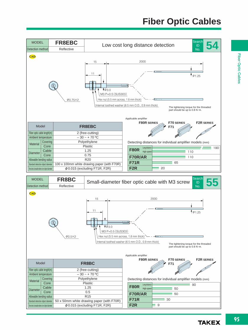
95
FiberOpticCables
Fiber Optic Cables
MODEL FR8EBCDetection method Reflective
Low cost long distance detectionSearch
ID No. 54
The tightening torque for the threadedpart should be up to 0.8 N・m.
11φ1.25
200015
Internal toothed washer (6 5 mm O.D., 0.9 mm thick)
Hex nut (5.5 mm across, 1 8 mm thick)
M3 P=0.5(SUS303)
φ3.0
φ0.75×2
MODEL FR8BCDetection method Reflective
Small-diameter fiber optic cable with M3 screwSearch
ID No. 55
The tightening torque for the threadedpart should be up to 0.8 N・m.
11 φ1.25
200015
Internal toothed washer (6 5 mm O.D., 0.9 mm thick)
Hex nut (5 5 mm across, 1.8 mm thick)
M3 P=0.5(SUS303)
φ3.0
φ0.5×2
F80R SERIES F70 SERIES
F71F2R SERIES
Applicable amplifier
F80R SERIES F70 SERIES
F71F2R SERIES
Applicable amplifier
F70R/ARF71RF2R
F80R
Detecting distances for individual amplifier models (mm)
110
190110
65
20
Long-distance
High-speed
F70R/ARF71RF2R
F80R
Detecting distances for individual amplifier models (mm)
50
9050
30
9
Long-distance
High-speed
Model
Fiber optic cable length(m)Ambient temperature
2 (free-cutting)– 30 ~ + 70 ºCPolyethylene
Plastic1.250.75R20
100 x 100mm white drawing paper (with F70R)φ0.015 (excluding F71R, F2R)
Allowable bending radiusStandard detection object diameter
Sma lest a lowable detec ion object diameter
Material
Diameter
CoveringCoreCableCore
FR8EBC
Model
Fiber optic cable length(m)Ambient temperature
2 (free-cutting)– 30 ~ + 70 ºCPolyethylene
Plastic1.250.5R15
50 x 50mm white drawing paper (with F70R)φ0.015 (excluding F71R, F2R)
Allowable bending radiusStandard detection object diameter
Sma lest a lowable detec ion object diameter
Material
Diameter
CoveringCoreCableCore
FR8BC
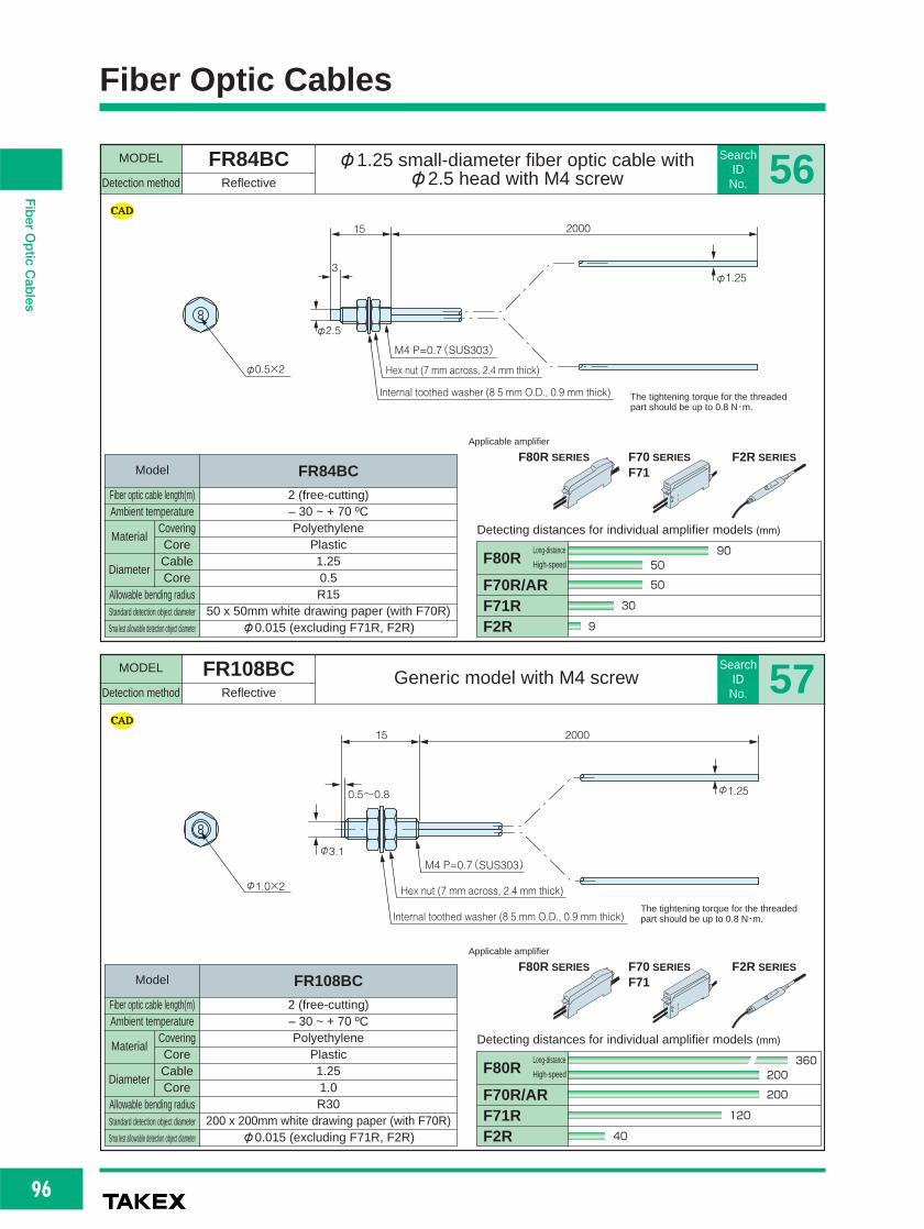
96
FiberOpticCables
Fiber Optic Cables
MODEL FR84BCDetection method Reflective
φ1.25 small-diameter fiber optic cable with φ2.5 head with M4 screw
SearchID
No. 56
The tightening torque for the threadedpart should be up to 0.8 N・m.
3φ1.25
200015
Internal toothed washer (8 5 mm O.D., 0.9 mm thick)
Hex nut (7 mm across, 2.4 mm thick)
M4 P=0.7(SUS303)
φ2.5
φ0.5×2
MODEL FR108BCDetection method Reflective
Generic model with M4 screwSearch
ID No. 57
The tightening torque for the threadedpart should be up to 0.8 N・m.
φ1.0×2
φ3.1
0.5~0.8 φ1.25
200015
Internal toothed washer (8 5 mm O.D., 0.9 mm thick)
Hex nut (7 mm across, 2.4 mm thick)
M4 P=0.7(SUS303)
F80R SERIES F70 SERIES
F71F2R SERIES
Applicable amplifier
F80R SERIES F70 SERIES
F71F2R SERIES
Applicable amplifier
F70R/ARF71RF2R
F80R
Detecting distances for individual amplifier models (mm)
200
360200
120
40
Long-distance
High-speed
F70R/ARF71RF2R
F80R
Detecting distances for individual amplifier models (mm)
50
9050
30
9
Long-distance
High-speed
Model
Fiber optic cable length(m)Ambient temperature
2 (free-cutting)– 30 ~ + 70 ºCPolyethylene
Plastic1.250.5R15
50 x 50mm white drawing paper (with F70R)φ0.015 (excluding F71R, F2R)
Allowable bending radiusStandard detection object diameter
Sma lest allowable detection object diameter
Material
Diameter
CoveringCoreCableCore
FR84BC
Model
Fiber optic cable length(m)Ambient temperature
2 (free-cutting)– 30 ~ + 70 ºCPolyethylene
Plastic1.251.0R30
200 x 200mm white drawing paper (with F70R)φ0.015 (excluding F71R, F2R)
Allowable bending radiusStandard detection object diameter
Sma lest allowable detection object diameter
Material
Diameter
CoveringCoreCableCore
FR108BC

97
FiberOpticCables
Fiber Optic Cables
MODEL FR7BCDetection method Reflective
Low-cost, φ2.5mm head with M6 screwSearch
ID No. 58
The tightening torque for the threadedpart should be up to 0.8 N・m.
φ2.5
3φ2.2
200017
Internal toothed washer (11 mm O.D., 1.2 mm thick)
Hex nut (8 mm across, 1.5 mm thick)
M6 P=0.75(SUS303)
φ1.0×2
MODEL FR5BCDetection method Reflective
M6 screw, long-distance detectionSearch
ID No. 59
The tightening torque for the threadedpart should be up to 0.8 N・m.
φ1.0×2
φ4.8
1
φ2.2
200023
Internal toothed washer (11 mm O.D., 1.2 mm thick)
Hex nut (9.8 mm across, 3.6 mm thick)
M6 P=1
φ6.0
15 (8)
F80R SERIES F70 SERIES
F71F2R SERIES
Applicable amplifier
F80R SERIES F70 SERIES
F71F2R SERIES
Applicable amplifier
F70R/ARF71RF2R
F80R
Detecting distances for individual amplifier models (mm)
180
320180
100
35
Long-distance
High-speed
F70R/ARF71RF2R
F80R
Detecting distances for individual amplifier models (mm)
180
320180
100
35
Long-distance
High-speed
Model
Fiber optic cable length(m)Ambient temperature
2 (free-cutting)– 30 ~ + 70 ºCPolyethylene
Plastic2.21.0R30
200 x 200mm white drawing paper (with F70R)φ0.015 (excluding F71R, F2R)
Allowable bending radiusStandard detection object diameter
Sma lest a lowable detec ion object diameter
Material
Diameter
CoveringCoreCableCore
FR7BC
Model
Fiber optic cable length(m)Ambient temperature
2 (free-cutting)– 30 ~ + 70 ºCPolyethylene
Plastic2.21.0R30
200 x 200mm white drawing paper (with F70R)φ0.015 (excluding F71R, F2R)
Allowable bending radiusStandard detection object diameter
Sma lest a lowable detec ion object diameter
Material
Diameter
CoveringCoreCableCore
FR5BC

98
FiberOpticCables
Fiber Optic Cables
MODEL FR91Y10Detection method Reflective
φ1.5 unthreaded, allowable bending radius 4 mmSearch
ID No. 60
LR RL
φ1.0
φ3.7
φ2.0 φ3.2 φ2.2
(3.7 mm across)φ5.3
10
(20) 100
35
1000
φ1.5
φ0.265×4
End face detail
Head (SUS303)
MODEL FR93BCDetection method Reflective
φ3 unthreaded short head, allowable bendingradius 4 mm
SearchID
No. 61
φ1.0
10 2000
φ3.0
Head (SUS303)φ0.25×8
End face detail
F80R SERIES F70 SERIES
F71F2R SERIES
Applicable amplifier
F80R SERIES F70 SERIES
F71F2R SERIES
Applicable amplifier
F70R/ARF71RF2R
F80R
Detecting distances for individual amplifier models (mm)
20
4020
12
4
Long-distance
High-speed
F70R/ARF71RF2R
F80R
Detecting distances for individual amplifier models (mm)
30
6030
18
6
Long-distance
High-speed
Model
Fiber optic cable length(m)Ambient temperature
1– 30 ~ + 70 ºCPolyethylene
Plastic1.0
φ0265 x 4R4
50 x 50mm white drawing paper (with F70R)φ0.015 (excluding F71R)
Allowable bending radiusStandard detection object diameter
Sma lest allowable detection object diameter
Material
Diameter
CoveringCoreCableCore
FR91Y10
Model
Fiber optic cable length(m)Ambient temperature
2 (free-cutting)– 30 ~ + 70 ºCPolyethylene
Plastic1.0
0.25 x 8R4
50 x 50mm white drawing paper (with F70R)φ0.015 (excluding F71R, F2R)
Allowable bending radiusStandard detection object diameter
Sma lest allowable detection object diameter
Material
Diameter
CoveringCoreCableCore
FR93BC

99
FiberOpticCables
Fiber Optic Cables
MODEL FR19YBCDetection method Reflective
M3 threaded short head, allowable minimumbending radius 1.0 mm
SearchID No. 62
The tightening torque for the threadedpart should be up to 0.8 N・m.
MODEL FR8YBCDetection method Reflective
M3 screw, allowable bending radius 4 mmSearch
ID No. 63
The tightening torque for the threadedpart should be up to 0.8 N・m.
φ0.5×2
φ1.0
200010
Internal toothed washer (6.5 mm O.D., 0.9 mm thick)
Hex nut (5.5 mm across, 1.8 mm thick)
M3 P=0.5(SUS303)
11 φ1.25
200015
Internal toothed washer (6 5 mm O.D., 0.9 mm thick)
Hex nut (5 5 mm across, 1.8 mm thick)
M3 P=0.5(SUS303)
φ3.0
φ0.25×2
F80R SERIES F70 SERIES
F71F2R SERIES
Applicable amplifier
F80R SERIES F70 SERIES
F71F2R SERIES
Applicable amplifier
F70R/ARF71RF2R
F80R
Detecting distances for individual amplifier models (mm)
13
4020
8
3
Long-distance
High-speed
F70R/ARF71RF2R
F80R
Detecting distances for individual amplifier models (mm)
10
2010
6
2
Long-distance
High-speed
Model
Fiber optic cable length(m)Ambient temperature
2 (free-cutting)– 30 ~ + 70 ºCPolyethylene
Plastic1.0
0.5 (multi-core)R1
25 x 25mm white drawing paper (with F70R)φ0.015 (excluding F71R, F2R)
Allowable bending radiusStandard detection object diameter
Sma lest a lowable detec ion object diameter
Material
Diameter
CoveringCoreCableCore
FR19YBC
Model
Fiber optic cable length(m)Ambient temperature
2 (free-cutting)– 30 ~ + 70 ºCPolyethylene
Plastic1.250.25R4
25 x 25mm white drawing paper (with F70R)φ0.015 (excluding F71R, F2R)
Allowable bending radiusStandard detection object diameter
Sma lest a lowable detec ion object diameter
Material
Diameter
CoveringCoreCableCore
FR8YBC

100
FiberOpticCables
Fiber Optic Cables
MODEL FR84YBCDetection method Reflective
M4 screw, allowable minimum bending radius 4 mmSearch
ID No. 64
The tightening torque for the threadedpart should be up to 0.8 N・m.
φ0.25×8
φ2.5 φ1.25
15
3 M4、P=0.7(SUS)
2000
End face detail Internal toothed washer (8.5 mm O.D., 0.9 mm thick)
Hex nut (7 mm across, 2.4 mm thick)
MODEL FR194YBCDetection method Reflective
M4 screw, allowable minimum bending radius 1.0 mmSearch
ID No. 65
The tightening torque for the threadedpart should be up to 0.8 N・m.
0.5~0.8 M4、P=0.7(SUS)
φ3.1
φ1.0
15 2000
φ0.5×2
End face detailInternal toothed washer (8.5 mm O.D., 0.9 mm thick)
Hex nut (7 mm across, 2.4 mm thick)
F80R SERIES F70 SERIES
F71F2R SERIES
Applicable amplifier
F80R SERIES F70 SERIES
F71F2R SERIES
Applicable amplifier
F70R/ARF71RF2R
F80R
Detecting distances for individual amplifier models (mm)
30
6030
16
7
Long-distance
High-speed
F70R/ARF71RF2R
F80R
Detecting distances for individual amplifier models (mm)
13
4020
8
3
Long-distance
High-speed
Model
Fiber optic cable length(m)Ambient temperature
2 (free-cutting)– 30 ~ + 70 ºCPolyethylene
Plastic1.25
0.25 x 8R4
50 x 50mm white drawing paper (with F70R)φ0.015 (excluding F71R, F2R)
Allowable bending radiusStandard detection object diameter
Sma lest allowable detection object diameter
Material
Diameter
CoveringCoreCableCore
FR84YBC
Model
Fiber optic cable length(m)Ambient temperature
2 (free-cutting)– 30 ~ + 70 ºCPolyethylene
Plastic1.0
0.5 (multi-core)R1
25 x 25mm white drawing paper (with F70R)φ0.015 (excluding F71R, F2R)
Allowable bending radiusStandard detection object diameter
Sma lest allowable detection object diameter
Material
Diameter
CoveringCoreCableCore
FR194YBC

101
FiberOpticCables
Fiber Optic Cables
MODEL FR5YBCDetection method Reflective
M6 screw, allowable minimum bending radius 1.0 mmSearch
ID No. 66
The tightening torque for the threadedpart should be up to 0.8 N・m.
φ1.0×2
φ4.8
1
15 8
φ2.2
Internal toothed washer (11 mm O.D., 1.2 mm thick)
Hex nut (9.8 mm across, 3.6 mm thick)
M6 P=1
φ6.0
200023
MODEL FR7YBCDetection method Reflective
M6 screw short head, allowable minimumbending radius 1.0 mm
SearchID No. 67
The tightening torque for the threadedpart should be up to 0.8 N・m.
φ2.5
φ1.0×2
3 φ2.2
200015
Internal toothed washer (11 mm O.D., 1.2 mm thick)
Hex nut (8 mm across, 1.5 mm thick)
M6 P=0.75(SUS303)
F80R SERIES F70 SERIES
F71F2R SERIES
Applicable amplifier
F80R SERIES F70 SERIES
F71F2R SERIES
Applicable amplifier
F70R/ARF71RF2R
F80R
Detecting distances for individual amplifier models (mm)
120
220120
70
25
Long-distance
High-speed
F70R/ARF71RF2R
F80R
Detecting distances for individual amplifier models (mm)
120
220120
70
25
Long-distance
High-speed
Model
Fiber optic cable length(m)Ambient temperature
2 (free-cutting)– 30 ~ + 70 ºCPolyethylene
Plastic2.2
1.0 (multi-core)R1
200 x 200mm white drawing paper (with F70R)φ0.015 (excluding F71R, F2R)
Allowable bending radiusStandard detection object diameter
Sma lest a lowable detec ion object diameter
Material
Diameter
CoveringCoreCableCore
FR5YBC
Model
Fiber optic cable length(m)Ambient temperature
2 (free-cutting)– 30 ~ + 70 ºCPolyethylene
Plastic2.2
1.0 (multi-core)R1
200 x 200mm white drawing paper (with F70R)φ0.015 (excluding F71R, F2R)
Allowable bending radiusStandard detection object diameter
Sma lest a lowable detec ion object diameter
Material
Diameter
CoveringCoreCableCore
FR7YBC

102
FiberOpticCables
Fiber Optic Cables
MODEL GXK seriesDetection method Reflective
Allowable bending radius 3.5 mm is achieved with glass fiber, excellent space saving
SearchID
No. 68
φ2.5
Binding diameter:φ1.0
3
L17
Internal toothed washer (11 mm O.D., 1.2 mm thick)
Hex nut (8 mm across, 1.5 mm thick)
M6 P=0.75(SUS303)
φ2.2
φ2.0
10
MODEL FXN84BCDetection method Coaxial reflective
Narrow-view coaxial with 1 transmitting and 9 receiving fibers
SearchID
No. 69
The tightening torque for the threadedpart should be up to 0.8 N・m.
3φ1.25
Internal toothed washer (8 5 mm O.D., 0.9 mm thick)
Hex nut (7 mm across, 2.4 mm thick)
M4 P=0.7(SUS303)φ2.5
φ0.5×1 (transmission)φ0.25×9 (reception)
200015
End face
The tightening torque for the threadedpart should be up to 0.8 N・m.
F2R SERIES
Applicable amplifier
F80R SERIES F70 SERIES
F71F2R SERIES
Applicable amplifier
F2R
Detecting distances for individual amplifier models (mm)
20
F70R/ARF71RF2R
F80R
Detecting distances for individual amplifier models (mm)
22
4022
13
5
Long-distance
High-speed
Model
Fiber optic cable length(m)Ambient temperature
0.5 1– 30 ~ + 70 ºCVinyl chloride
Glass2.0
Binding diameter: 1.0 mmR3.5
25 x 25mm white drawing paper φ0.02
Allowable bending radiusStandard detection object diameter
Sma lest allowable detection object diameter
Material
Diameter
CoveringCoreCableCore
GXK9605 GXK9610
Model
Fiber optic cable length(m)Ambient temperature
2 (free-cutting)– 30 ~ + 70 ºCPolyethylene
Plastic1.25
Transmission: φ0.5 x 1 / Reception: φ0.25 x 9R15
25 x 25mm white drawing paper (with F70R)φ0.015 (excluding F71R, F2R)
Allowable bending radiusStandard detection object diameter
Sma lest allowable detection object diameter
Material
Diameter
CoveringCoreCableCore
FXN84BC

103
FiberOpticCables
Fiber Optic Cables
MODEL FXN841BCDetection method Coaxial reflective
Narrow-view, φ1.5 spot at 5 mmSearch
ID No. 70
The tightening torque for the threadedpart should be up to 0.8 N・m.
3φ1.25
Internal toothed washer (8.5 mm O.D., 0.9 mm thick)
Hex nut (7 mm across, 2.4 mm thick)
M4 P=0.7(SUS303)φ2.5
φ0.5×1 (transmission)φ0.25×4 (reception)
(5 dummy cables)
200015
End face detail
MODEL FR707BCDetection method Reflective
Narrow-view, angle of aperture 10゜Search
ID No. 71
6.3 15 2000
2-φ2.2
4.49.5
Head (black ABS)2-φ3.5 (lens diameter)
F80R SERIES F70 SERIES
F71
Applicable amplifier
F80R SERIES F70 SERIES
F71
Applicable amplifier
F70R/ARF71R
F80R
Detecting distances for individual amplifier models (mm)
30~150
30~27030~150
30~110
Long-distance
High-speed
F70R/ARF71R
F80R
Detecting distances for individual amplifier models (mm)
5.5
126
3
Long-distance
High-speed
Model
Fiber optic cable length(m)Ambient temperature
2 (free-cutting)– 30 ~ + 70 ºCPolyethylene
Plastic1.25
Transmission: φ0.5 x 1 / Reception: φ0.25 x 4R15
25 x 25mm white drawing paper (with F70R)φ0.015 (excluding F71R, F2R)
Allowable bending radiusStandard detection object diameter
Sma lest a lowable detec ion object diameter
Material
Diameter
CoveringCoreCableCore
FXN841BC
Model
Fiber optic cable length(m)Ambient temperature
2 (free-cutting)– 30 ~ + 70 ºCPolyethylene
Plastic2.21.0R30
200 x 200mm white drawing paper (with F70R)φ0.3 (excluding F71R, F2R)
Allowable bending radiusStandard detection object diameter
Sma lest a lowable detec ion object diameter
Material
Diameter
CoveringCoreCableCore
FR707BC

104
FiberOpticCables
Fiber Optic Cables
MODEL FRS83BCDetection method Reflective
φ1.3 head, φ1.25 fiber optic cableSearch
ID No. 72
Do not bend the part marked with *.
φ0.5×2φ1.3
15
5
2000
Head (SUS303)φ1.48
φ3.0
φ1.25
Guide (SUS304)
15*
MODEL FRS801BCDetection method Reflective
φ4 unthreaded SS 22 mmSearch
ID No. 73
Do not bend the part marked with *.
φ0.5×2
φ1.3(Drawn)
φ1.48
5
22* 15 2000
φ1.25
φ4.0
End face detail
F80R SERIES F70 SERIES
F71F2R SERIES
Applicable amplifier
F80R SERIES F70 SERIES
F71F2R SERIES
Applicable amplifier
F70R/ARF71RF2R
F80R
Detecting distances for individual amplifier models (mm)
50
9050
30
9
Long-distance
High-speed
F70R/ARF71RF2R
F80R
Detecting distances for individual amplifier models (mm)
50
9050
30
9
Long-distance
High-speed
Model
Fiber optic cable length(m)Ambient temperature
2 (free-cutting)– 30 ~ + 70 ºCPolyethylene
Plastic1.250.5R15
50 x 50mm white drawing paper (with F70R)φ0.015 (excluding F71R, F2R)
Allowable bending radiusStandard detection object diameter
Sma lest allowable detection object diameter
Material
Diameter
CoveringCoreCableCore
FRS83BC
Model
Fiber optic cable length(m)Ambient temperature
2 (free-cutting)– 30 ~ + 70 ºCPolyethylene
Plastic1.250.5R15
50 x 50mm white drawing paper (with F70R)φ0.015 (excluding F71R, F2R)
Allowable bending radiusStandard detection object diameter
Sma lest allowable detection object diameter
Material
Diameter
CoveringCoreCableCore
FRS801BC

105
FiberOpticCables
Fiber Optic Cables
MODEL FRS8BCDetection method Reflective
70 mm SS tube with M3 screw, φ1.25 fiber optic cable
SearchID No. 75
Do not bend the part marked with *. The tightening torque should be up to0.8 N・m.
5
φ1.25
200015
Internal toothed washer (6.5 mm O.D., 0.9 mm thick)
Stainless tube (SUS 304)
Hex nut (5.5 mm across, 1.8 mm thick)
M3 P=0.5(SUS303)φ3.0φ2.0φ1.48φ1.3
70
Bendable(R10)10*
5
10* 11
φ0.5×2
MODEL FRS806BCDetection method Reflective
SS 40 mm with M3 screwSearch
ID No. 74
Do not bend the part marked with *. The tightening torque for the threadedpart should be up to 0.8 N・m.
φ0.5×2
φ1.3φ1.48
φ2.0φ3.0
φ1.25
5
10*
40
M3,P=0.5
15 2000
10*Bendable
(R10)
End face detail
5
Internal too hed washer (6 5 mm O.D., 0 9 mm hick)
Hex nut (5.5 mm across, 1.8 mm thick)
F80R SERIES F70 SERIES
F71F2R SERIES
Applicable amplifier
F80R SERIES F70 SERIES
F71F2R SERIES
Applicable amplifier
F70R/ARF71RF2R
F80R
Detecting distances for individual amplifier models (mm)
50
9050
30
9
Long-distance
High-speed
F70R/ARF71RF2R
F80R
Detecting distances for individual amplifier models (mm)
50
9050
30
9
Long-distance
High-speed
Model
Fiber optic cable length(m)Ambient temperature
2 (free-cutting)– 30 ~ + 70 ºCPolyethylene
Plastic1.250.5
SUS part: R10 / Fiber optic cable: R1550 x 50mm white drawing paper (with F70R)
φ0.015 (excluding F71R, F2R)
Allowable bending radiusStandard detection object diameter
Sma lest a lowable detec ion object diameter
Material
Diameter
CoveringCoreCableCore
FRS806BC
Model
Fiber optic cable length(m)Ambient temperature
2 (free-cutting)– 30 ~ + 70 ºCPolyethylene
Plastic1.250.5
SUS part: R10 / Fiber optic cable: R1550 x 50mm white drawing paper (with F70R)
φ0.015 (excluding F71R, F2R)
Allowable bending radiusStandard detection object diameter
Sma lest a lowable detec ion object diameter
Material
Diameter
CoveringCoreCableCore
FRS8BC

106
FiberOpticCables
Fiber Optic Cables
MODEL FRS2003J seriesDetection method Reflective
φ0.9 head, 35 mm SS tube with M4 screwSearch
ID No. 76
5
L15
Internal toothed washer (8.5 mm O.D., 0.9 mm thick)
Stainless tube (SUS 304)Hex nut (7 mm across, 2.4 mm thick)
M4 P=0.7
φ1.0 φ2.5 φ2.1φ0.87
35
Bendable(R10)
10*
5
10*
φ0.25×2With special connector
MODEL FRS84BCDetection method Reflective
70 mm SS tube with M4 screwSearch
ID No. 77
Do not bend the part marked with *. The tightening torque for the threadedpart should be up to 0.8 N・m.
5
φ1.25
Internal toothed washer (8 5 mm O.D., 0.9 mm thick)
Stainless tube (SUS 304)
Hex nut (7 mm across, 2.4 mm thick)
M4 P=0.7(SUS303)
φ1.48 φ2.5φ1.3
Bendable(R10)10*
5
10*
φ0.5×2
20001570
Do not bend the part marked with *. The tightening torque for the threadedpart should be up to 0.8 N・m.
F80R SERIES F70 SERIES
F71
Applicable amplifier
F80R SERIES F70 SERIES
F71F2R SERIES
Applicable amplifier
F70R/ARF71RF2R
F80R
Detecting distances for individual amplifier models (mm)
50
9050
30
9
Long-distance
High-speed
F70R/ARF71R
F80R
Detecting distances for individual amplifier models (mm)
13
2313
7
Long-distance
High-speed
Model
Fiber optic cable length(m)Ambient temperature
0.5 1– 30 ~ + 70 ºCPolyethylene
Plastic2.1
0.25SUS part: R10 / Fiber optic cable: R15
25 x 25mm white drawing paper (with F70R)φ0.015
Allowable bending radiusStandard detection object diameter
Sma lest allowable detection object diameter
Material
Diameter
CoveringCoreCableCore
FRS2053J FRS2103J
Model
Fiber optic cable length(m)Ambient temperature
2 (free-cutting)– 30 ~ + 70 ºCPolyethylene
Plastic1.250.5
SUS part: R10 / Fiber optic cable: R1550 x 50mm white drawing paper (with F70R)
φ0.015 (excluding F71R, F2R)
Allowable bending radiusStandard detection object diameter
Sma lest allowable detection object diameter
Material
Diameter
CoveringCoreCableCore
FRS84BC

107
FiberOpticCables
Fiber Optic Cables
MODEL FRS200J seriesDetection method Reflective
φ0.87 head, 70 mm SS tube with M4 screwSearch
ID No. 78
With special connector
5
L15
Internal toothed washer (8 5 mm O.D., 0.9 mm thick)Stainless tube Hex nut (7 mm across, 2.4 mm thick)
M4 P=0.7(SUS303)
φ1.0 φ2.5 φ2.1φ0.87
70
Bendable(R10)10*
5
10*
φ0.25×2
MODEL FRS53BCDetection method Reflective
35 mm SS tube with M6 screwSearch
ID No. 79
φ0.5×2
φ1.37
15
φ2.2
23 2000
Internal toothed washer (11 mm O.D., 1.2 mm thick)
Hex nut (9.8 mm across, 3.6 mm thick)
M6 P=1φ6.0
φ1.5φ2.5
10*
5 5
10*Bendable(R10)
35
Do not bend the part marked with *. The tightening torque for the threadedpart should be up to 0.8 N・m.
Do not bend the part marked with *. The tightening torque for the threadedpart should be up to 0.8 N・m.
F80R SERIES F70 SERIES
F71
Applicable amplifier
F80R SERIES F70 SERIES
F71F2R SERIES
Applicable amplifier
F70R/ARF71RF2R
F80R
Detecting distances for individual amplifier models (mm)
50
9050
30
9
Long-distance
High-speed
F70R/ARF71R
F80R
Detecting distances for individual amplifier models (mm)
13
2313
7
Long-distance
High-speed
Model
Fiber optic cable length(m)Ambient temperature
0.5 1– 30 ~ + 70 ºCPolyethylene
Plastic2.1
0.25SUS part: R10 / Fiber optic cable: R15
25 x 25mm white drawing paper (with F70R)φ0.015
Allowable bending radiusStandard detection object diameter
Sma lest a lowable detec ion object diameter
Material
Diameter
CoveringCoreCableCore
FRS205J FRS210J
Model
Fiber optic cable length(m)Ambient temperature
2 (free-cutting)– 30 ~ + 70 ºCPolyethylene
Plastic2.20.5
SUS part: R10/ Fiber optic cable: R1550 x 50mm white drawing paper (with F70R)
φ0.015 (excluding F71R, F2R)
Allowable bending radiusStandard detection object diameter
Sma lest a lowable detec ion object diameter
Material
Diameter
CoveringCoreCableCore
FRS53BC

108
FiberOpticCables
Fiber Optic Cables
MODEL FRS5BCDetection method Reflective
70 mm SS tube with M6 screwSearch
ID No. 81
Do not bend the part marked with *. The tightening torque for the threadedpart should be up to 0.8 N・m.
φ0.5×2
φ1.37
15
φ2.2
200023
Internal toothed washer (11 mm O.D., 1.2 mm thick)
Stainless tube (SUS 304)Hex nut (9.8 mm across, 3.6 mm thick)
M6 P=1φ6.0
φ1.5φ2.5
10*5
10*Bendable(R10)
70
MODEL FRS105BCDetection method Reflective
M6 screw SS 40 mmSearch
ID No. 80
The tightening torque for the threadedpart should be up to 0.8 N・m.
φ1.5×2
End face φ3.75φ2.2
40
M6、P=0.75
17 2000
Internal too hed washer (11 mm O.D., 1.2 mm hick)
Hex nut (8 mm across, 1.5 mm thick)
F80R SERIES F70 SERIES
F71F2R SERIES
Applicable amplifier
F80R SERIES F70 SERIES
F71F2R SERIES
Applicable amplifier
F70R/ARF71RF2R
F80R
Detecting distances for individual amplifier models (mm)
320
570320
190
50
Long-distance
High-speed
F70R/ARF71RF2R
F80R
Detecting distances for individual amplifier models (mm)
50
9050
30
9
Long-distance
High-speed
Model
Fiber optic cable length(m)Ambient temperature
2 (free-cutting)– 30 ~ + 70 ºCPolyethylene
Plastic2.21.5R45
400 x 400mm white drawing paper(with F70R)φ0.015 (excluding F71R, F2R)
Allowable bending radiusStandard detection object diameter
Sma lest allowable detection object diameter
Material
Diameter
CoveringCoreCableCore
FRS105BC
Model
Fiber optic cable length(m)Ambient temperature
2 (free-cutting)– 30 ~ + 70 ºCPolyethylene
Plastic2.20.5
SUS part: R10 / Fiber optic cable: R1550 x 50mm white drawing paper (with F70R)
φ0.015 (excluding F71R, F2R)
Allowable bending radiusStandard detection object diameter
Sma lest allowable detection object diameter
Material
Diameter
CoveringCoreCableCore
FRS5BC

109
FiberOpticCables
Fiber Optic Cables
MODEL FRSV83BCDetection method Reflective
Side-view φ1.48 head, 20 mm SS tube with φ3 unthreaded head-unit
SearchID No. 82
Do not bend the part marked with *.
φ1.25
φ3.0
20001520*
Guide (SUS304)
Head (SUS303)
0.8
φ1.48
0.9
A
1.1
A detail
MODEL FRSV55BCDetection method Reflective
φ2.1 head, 70 mm SS tube with φ5 unthreaded partSearch
ID No. 83
Do not bend the part marked with *.
3.5
1
2.5
φ2.2
200020
Head (SUS303)
φ2.1
70*Unbendable
Guide (SUS304)
φ5.0
F80R SERIES F70 SERIES
F71F2R SERIES
Applicable amplifier
F80R SERIES F70 SERIES
F71F2R SERIES
Applicable amplifier
F70R/ARF71RF2R
F80R
Detecting distances for individual amplifier models (mm)
50
9050
30
10
Long-distance
High-speed
F70R/ARF71RF2R
F80R
Detecting distances for individual amplifier models (mm)
20
4020
12
4
Long-distance
High-speed
Model
Fiber optic cable length(m)Ambient temperature
2 (free-cutting)– 30 ~ + 70 ºCPolyethylene
Plastic1.250.5R15
25 x 25mm white drawing paper (with F70R)φ0.015 (excluding F71R, F2R)
Allowable bending radiusStandard detection object diameter
Sma lest a lowable detec ion object diameter
Material
Diameter
CoveringCoreCableCore
FRSV83BC
Model
Fiber optic cable length(m)Ambient temperature
2 (free-cutting)– 30 ~ + 70 ºCPolyethylene
Plastic2.2
0.75R30
50 x 50mm white drawing paper (with F70R)φ0.015 (excluding F71R, F2R)
Allowable bending radiusStandard detection object diameter
Sma lest a lowable detec ion object diameter
Material
Diameter
CoveringCoreCableCore
FRSV55BC

110
FiberOpticCables
Fiber Optic Cables
MODEL FRSV8BCDetection method Reflective
Side-view φ1.48 head, 20 mm SS tube with M3 screwSearch
ID No. 84
Do not bend the part marked with *. The tightening torque for the threadedpart should be up to 0.8 N・m.
φ1.25
200015
11
20*
Internal toothed washer (6.5 mm O.D., 0.9 mm thick)
Hex nut (5.5 mm across, 1.8 mm thick)
M3 P=0.5φ3.0
0.8
1.1
0.9
A
φ1.48
A detail
MODEL FRSV84BCDetection method Reflective
M4 screw SS 70 mmSearch
ID No. 85
Do not bend the part marked with *. The tightening torque for the threadedpart should be up to 0.8 N・m.
φ2.1 A
70*(Unbendable)
M4 P=0.7Guide (SUS 304)
Hex nut (7 mm across, 2.4 mm thick)Internal toothed washer (8 5 mm O.D., 0.9 mm thick)
15 2000
φ1.25
Side detail of A
1
1.5
3.5
F80R SERIES F70 SERIES
F71F2R SERIES
Applicable amplifier
F80R SERIES F70 SERIES
F71F2R SERIES
Applicable amplifier
F70R/ARF71RF2R
F80R
Detecting distances for individual amplifier models (mm)
19
4020
10
4
Long-distance
High-speed
F70R/ARF71RF2R
F80R
Detecting distances for individual amplifier models (mm)
50
9050
30
10
Long-distance
High-speed
Model
Fiber optic cable length(m)Ambient temperature
2 (free-cutting)– 30 ~ + 70 ºCPolyethylene
Plastic1.250.5R15
25 x 25mm white drawing paper (with F70R)φ0.015 (excluding F71R, F2R)
Allowable bending radiusStandard detection object diameter
Sma lest allowable detection object diameter
Material
Diameter
CoveringCoreCableCore
FRSV8BC
Model
Fiber optic cable length(m)Ambient temperature
2 (free-cutting)– 30 ~ + 70 ºCPolyethylene
Plastic1.250.75R20
50 x 50mm white drawing paper (with F70R)φ0.015 (excluding F71R, F2R)
Allowable bending radiusStandard detection object diameter
Sma lest allowable detection object diameter
Material
Diameter
CoveringCoreCableCore
FRSV84BC

111
FiberOpticCables
Fiber Optic Cables
MODEL FRSV5BCDetection method Reflective
φ2.1 head, 65 mm SS tube with M6 screwSearch
ID No. 86
Do not bend the part marked with *. The tightening torque for the threadedpart should be up to 0.8 N・m.
3.5
1
2.5φ4.5
φ2.2
200023
5
Internal toothed washer (11 mm O.D., 1.2 mm thick)
Hex nut (9.8 mm across, 3.6 mm thick)
M6 P=1
15
65*(Unbendable)
Stainless tube (SUS 304)
φ6.0φ2.1
MODEL FX83BCDetection method Coaxial reflective
Coaxial with 1 transmitting and 4 receiving fibers with φ3 unthreaded head-unit
SearchID No. 87
Head (SUS 303)
φ1.25
200015
φ3.0
φ0.5×1φ0.265×4
F80R SERIES F70 SERIES
F71F2R SERIES
Applicable amplifier
F80R SERIES F70 SERIES
F71F2R SERIES
Applicable amplifier
F70R/ARF71RF2R
F80R
Detecting distances for individual amplifier models (mm)
50
9050
30
10
Long-distance
High-speed
F70R/ARF71RF2R
F80R
Detecting distances for individual amplifier models (mm)
44
9050
25
7
Long-distance
High-speed
Model
Fiber optic cable length(m)Ambient temperature
2 (free-cutting)– 30 ~ + 70 ºCPolyethylene
Plastic2.2
0.75R30
50 x 50mm white drawing paper (with F70R)φ0.015 (excluding F71R, F2R)
Allowable bending radiusStandard detection object diameter
Sma lest a lowable detec ion object diameter
Material
Diameter
CoveringCoreCableCore
FRSV5BC
Model
Fiber optic cable length(m)Ambient temperature
2 (free-cutting)– 30 ~ + 70 ºCPolyethylene
Plastic1.25
φ0.5 x 1 (transmission)/φ0.265 x 4 (receptopn)R15
50 x 50mm white drawing paper (with F70R)φ0.015 (excluding F71R, F2R)
Allowable bending radiusStandard detection object diameter
Sma lest a lowable detec ion object diameter
Material
Diameter
CoveringCoreCableCore
FX83BC

112
FiberOpticCables
Fiber Optic Cables
MODEL FX801BCDetection method Coaxial reflective
Coaxial with 1 transmitting and 9 receivingfibers with M3 screw
SearchID
No. 88
The tightening torque for the threadedpart should be up to 0.8 N・m.
21
End face detailφ1.25
200025
Internal toothed washer (6.5 mm O.D., 0.9 mm thick)
Hex nut (5.5 mm across, 1.8 mm thick)
M3 P=0.5(SUS303)
φ3.0φ0.5×1φ0.25×9
MODEL FX84BCDetection method Coaxial reflective
φ2.5mm coaxial cable with 1 transmitting and 4 receiving fibers with M4 screw
SearchID
No. 89
The tightening torque for the threadedpart should be up to 0.8 N・m.
3 φ1.25
200015
Internal toothed washer (8 5 mm O.D., 0.9 mm thick)
Hex nut (7 mm across, 2.4 mm thick)
M4 P=0.7(SUS303)φ2.5
φ0.5×1φ0.25×4(5 dummy cables)
End face detail
F80R SERIES F70 SERIES
F71F2R SERIES
Applicable amplifier
F80R SERIES F70 SERIES
F71F2R SERIES
Applicable amplifier
F70R/ARF71RF2R
F80R
Detecting distances for individual amplifier models (mm)
44
9050
25
7
Long-distance
High-speed
F70R/ARF71RF2R
F80R
Detecting distances for individual amplifier models (mm)
55
11060
33
10
Long-distance
High-speed
Model
Fiber optic cable length(m)Ambient temperature
2 (free-cutting)– 30 ~ + 70 ºCPolyethylene
Plastic1.25
φ0.5 (transmission) / φ0.25 x 9 (reception)R15
50 x 50mm white drawing paper (with F70R)φ0.015 (excluding F71R, F2R)
Allowable bending radiusStandard detection object diameter
Sma lest allowable detection object diameter
Material
Diameter
CoveringCoreCableCore
FX801BC
Model
Fiber optic cable length(m)Ambient temperature
2 (free-cutting)– 30 ~ + 70 ºCPolyethylene
Plastic1.25
φ0.5 x 1 (transmission) / φ0.25 x 4 (reception)R15
50 x 50mm white drawing paper (with F70R)φ0.015 (excluding F71R, F2R)
Allowable bending radiusStandard detection object diameter
Sma lest allowable detection object diameter
Material
Diameter
CoveringCoreCableCore
FX84BC

113
FiberOpticCables
Fiber Optic Cables
MODEL FX8401BCDetection method Coaxial reflective
Coaxial cable minute light spot with lensSearch
ID No. 90
The tightening torque for the threadedpart should be up to 0.8 N・m.
Internal toothed washer (8 5 mm O.D., 0.9 mm thick)
Hex nut (7 mm across, 2.4 mm thick)
M4 P=0.7(SUS303)(5 dummy cables)φ0.25×4
φ0.5×1(transmission)
(reception)
0.5~0.8φ1.25
200015
φ3.1
End face detail
MODEL FX8404BCDetection method Coaxial reflective
Coaxial cable with 1 transmitting and 9 receiving fibers with M4 screw
SearchID No. 91
The tightening torque for the threadedpart should be up to 0.8 N・m.
Internal toothed washer (8.5 mm O.D., 0.9 mm thick)
Hex nut (7 mm across, 2.4 mm thick)
M4 P=0.7(SUS303)
0.5~0.8φ1.25
200015
φ3.1
φ0.5×1φ0.25×9
End face detail
F80R SERIES F70 SERIES
F71F2R SERIES
Applicable amplifier
F80R SERIES F70 SERIES
F71F2R SERIES
Applicable amplifier
F70R/ARF71RF2R
F80R
Detecting distances for individual amplifier models (mm)
44
9050
25
7
Long-distance
High-speed
F70R/ARF71RF2R
F80R
Detecting distances for individual amplifier models (mm)
55
11060
33
10
Long-distance
High-speed
Model
Fiber optic cable length(m)Ambient temperature
2 (free-cutting)– 30 ~ + 70 ºCPolyethylene
Plastic1.25
φ0.5 x 1 (transmission) / φ0.25 x 4 (reception)R15
50 x 50mm white drawing paper (with F70R)φ0.015 (excluding F71R, F2R)
Allowable bending radiusStandard detection object diameter
Sma lest a lowable detec ion object diameter
Material
Diameter
CoveringCoreCableCore
FX8401BC
Model
Fiber optic cable length(m)Ambient temperature
2 (free-cutting)– 30 ~ + 70 ºCPolyethylene
Plastic1.25
φ0.5 x 1 (transmission) / φ0.25 x 9 (reception)R15
50 x 50mm white drawing paper (with F70R)φ0.015 (excluding F71R, F2R)
Allowable bending radiusStandard detection object diameter
Sma lest a lowable detec ion object diameter
Material
Diameter
CoveringCoreCableCore
FX8404BC

114
FiberOpticCables
Fiber Optic Cables
MODEL FX200J seriesDetection method Coaxial reflective
Coaxial cable with 1 transmitting and 9 receiving fibers with M4 screw
SearchID
No. 92
Internal toothed washer (8.5 mm O.D., 0.9 mm thick)
Hex nut (7 mm across, 2.4 mm thick)
M4 P=0.7(SUS303)
0.5~0.8
φ2.2
L15
φ3.1
φ0.5×1φ0.25×9
End face detail
MODEL FX7BCDetection method Coaxial reflective
Lowest-cost φ2.5 coaxial cable with 1 transmittingand 4 receiving fiber optic cables with M6 screw
SearchID
No. 93
The tightening torque for the threadedpart should be up to 0.8 N・m.
φ2.5
3 φ2.2
200017
Internal toothed washer (11 mm O.D., 1.2 mm thick)
Hex nut (8 mm across, 1.5 mm thick)
M6 P=0.75(SUS303)φ0.75×1φ0.5×4
With special connector
F80R SERIES F70 SERIES
F71
Applicable amplifier
F80R SERIES F70 SERIES
F71F2R SERIES
Applicable amplifier
F70R/ARF71R
F80R
Detecting distances for individual amplifier models (mm)
75(65)
135(120)75(65)
45(35)
Long-distance
High-speed
F70R/ARF71RF2R
F80R
Detecting distances for individual amplifier models (mm)
130
230130
75
25
Long-distance
High-speed
Values in parentheses show detecting distances for combinations with FX220J.
The tightening torque for the threadedpart should be up to 0.8 N・m.
Model
Fiber optic cable length(m)Ambient temperature
0.5 1 2– 30 ~ + 70 ºCPolyethylene
Plastic2.2
φ0.5 x 1 (transmission) /φ0.25 x 9 (reception)R30
100 x 100mm white drawing paper (with F70R)φ0.015 (excluding F71R)
Allowable bending radiusStandard detection object diameter
Sma lest allowable detection object diameter
Material
Diameter
CoveringCoreCableCore
FX205J FX210J FX220J
Model
Fiber optic cable length(m)Ambient temperature
2 (free-cutting)– 30 ~ + 70 ºCPolyethylene
Plastic2.2
φ0.75 x 1 (transmission) /φ0.5 x 4 (reception)R30
200 x 200mm white drawing paper (with F70R)φ0.015 (excluding F71R, F2R)
Allowable bending radiusStandard detection object diameter
Sma lest allowable detection object diameter
Material
Diameter
CoveringCoreCableCore
FX7BC

115
FiberOpticCables
Fiber Optic Cables
MODEL FX716BCDetection method Coaxial reflective
Coaxial cable with longest detecting distanceSearch
ID No. 94
The tightening torque for the threadedpart should be up to 0.8 N・m.
φ2.5
3 φ2.2
200017
Internal toothed washer (11 mm O.D., 1.2 mm thick)
Hex nut (8 mm across, 1.5 mm thick)
M6 P=0.75(SUS303)
φ1.0×1φ0.265×16
End face detail
MODEL FZ801BCDetection method Limited reflection
Detection regardless of detected object colorSearch
ID No. 95
2- M3 threaded hole
Head: aluminum (black anodized aluminum)
16。
8。
20
8
8.4
φ1.25
20 2000
8 4
F80R SERIES F70 SERIES
F71F2R SERIES
Applicable amplifier
F80R SERIES F70 SERIES
F71
Applicable amplifier
F70R/ARF71RF2R
F80R
Detecting distances for individual amplifier models (mm)
170
300170
100
30
Long-distance
High-speed
F70R/ARF71R
F80R
Detecting distances for individual amplifier models (mm)
30
30
30
Long-distance
High-speed }
Model
Fiber optic cable length(m)Ambient temperature
2 (free-cutting)– 30 ~ + 70 ºCPolyethylene
Plastic2.2
φ1.0 x 1 (transmission) /φ0.265 x 16 (reception)R30
200 x 200mm white drawing paper (with F70R)φ0.015 (excluding F71R, F2R)
Allowable bending radiusStandard detection object diameter
Sma lest a lowable detec ion object diameter
Material
Diameter
CoveringCoreCableCore
FX716BC
Model
Fiber optic cable length(m)Ambient temperature
2 (free-cutting)– 30 ~ + 70 ºCPolyethylene
Plastic1.251.0R30
50 x 50mm white drawing paper (with F70R)φ0.015 (excluding F71R)
Allowable bending radiusStandard detection object diameter
Sma lest a lowable detec ion object diameter
Material
Diameter
CoveringCoreCableCore
FZ801BC

116
FiberOpticCables
Fiber Optic Cables
MODEL FZ802BCDetection method Limited reflection
Thin body of 3 mmSearch
ID No. 96
(1.85)3
2-φ1.8 lens
2-φ3.5×7.5 elongate hole
φ1.25
19
45
2000
31°
6.12
3.5
10 16.518
Head: aluminum (black anodized aluminum)
MODEL FZ804BCDetection method Limited reflection
Thin body of 3 mmSearch
ID No. 97
2-φ3.5 hole
φ1.25
2-φ1.0
3
3.6 10
18
7 7
7
2000
Head: aluminum (black anodized aluminum)
F80R SERIES F70 SERIES
F71
Applicable amplifier
F80R SERIES F70 SERIES
Applicable amplifier
F70R/ARF71R
F80R
Detecting distances for individual amplifier models (mm)
0~5
0~5
0~5
Long-distance
High-speed
F70R/AR
F80R
Detecting distances for individual amplifier models (mm)
5~17
5~17}Long-distance
High-speed
}
Model
Fiber optic cable length(m)Ambient temperature
2 (free-cutting)– 30 ~ + 70 ºCPolyethylene
Plastic1.250.5R15
50 x 50mm white drawing paper (with F70R)φ0.015 (excluding F71R)
Allowable bending radiusStandard detection object diameter
Sma lest allowable detection object diameter
Material
Diameter
CoveringCoreCableCore
FZ802BC
Model
Fiber optic cable length(m)Ambient temperature
2 (free-cutting)– 30 ~ + 70 ºCPolyethylene
Plastic1.250.5R15
50 x 50mm transparent glass plate (with F70R)φ0.015 (excluding F71R)
Allowable bending radiusStandard detection object diameter
Sma lest allowable detection object diameter
Material
Diameter
CoveringCoreCableCore
FZ804BC

117
FiberOpticCables
Fiber Optic Cables
MODEL FZ1901YBCDetection method Limited reflection
Limited reflection, allowable bending radius 1.0 mmSearch
ID No. 98
8
20
4.7°
9.4°
7 4
2000
20 8.4
2-φ3.4 hole
φ2.2
Head: aluminum (black anodized aluminum)
MODEL FZV8301BCDetection method Limited reflection
Ideal for fitting into robot hand with a depth ofonly 3 mm
SearchID No. 99
32
7 7
10 6
0.7
200018
1.5
Head: aluminum (black anodized aluminum)
2- M3 through hole
φ1.25
Window for transmitter and receiver
Use at a lower sensitivity for combination with F80R or F70R/AR.
F80R SERIES F70 SERIES
F71
Applicable amplifier
F80R SERIES F70 SERIES
F71
Applicable amplifier
F70R/ARF71R
F80R
Detecting distances for individual amplifier models (mm)
50
50
50
Long-distance
High-speed }
F70R/ARF71R
F80R
Detecting distances for individual amplifier models (mm)
0~20
0~20
0~20
Long-distance
High-speed }
Model
Fiber optic cable length(m)Ambient temperature
2 (free-cutting)– 30 ~ + 70 ºCPolyethylene
Plastic2.2
1.0 (multi-core)R1
50 x 50mm white drawing paper (with F70R)φ0.015 (excluding F71R)
Allowable bending radiusStandard detection object diameter
Sma lest a lowable detec ion object diameter
Material
Diameter
CoveringCoreCableCore
FZ1901YBC
Model
Fiber optic cable length(m)Ambient temperature
2 (free-cutting)– 30 ~ + 70 ºCPolyethylene
Plastic1.250.75R20
50 x 50mm transparent glass plate (with F70R)φ0.015 (excluding F71R)
Allowable bending radiusStandard detection object diameter
Sma lest a lowable detec ion object diameter
Material
Diameter
CoveringCoreCableCore
FZV8301BC

118
FiberOpticCables
Fiber Optic Cables
MODEL FZV191YBCDetection method Limited reflection
Ideal for glass substrate detection with allowable bending radius of only 1 mm
SearchID
No. 1005.5
20 2000
20
3 52.5
(14)
7 2-φ3.2 hole, φ6.1 counterbores (on both sides)
φ1.0
4
Window for transmitter and receiver
The tightening torque for the threadedpart should be up to 0.8 N・m.
The sensor may be activated even without detection objects when the amplifiersensitivity is too high. Be sure to adjust the sensitivity before use.
MODEL FZV8203BCDetection method Limited reflection
2-mm thin bodySearch
ID No. 101
6
2 2
10 6
0.7
1
Window for transmitterand receiver
7 7
18
2 M3 threaded through holes
2000
φ1.25
Head: aluminum (black anodized aluminum)
F80R SERIES F70 SERIES
Applicable amplifier
F80R SERIES F70 SERIES
F71
Applicable amplifier
F70R/AR
F80R
Detecting distances for individual amplifier models (mm)
0~6
0~6}Long-distance
High-speed
F70R/ARF71R
F80R
Detecting distances for individual amplifier models (mm)
0~19
0~19
0~19
Long-distance
High-speed }
Model
Fiber optic cable length(m)Ambient temperature
2 (free-cutting)– 30 ~ + 70 ºCPolyethylene
Plastic1.0
0.75 (multi-core)R1
Transparent glass plate–
Allowable bending radiusStandard detection object diameter
Sma lest allowable detection object diameter
Material
Diameter
CoveringCoreCableCore
FZV191YBC
Model
Fiber optic cable length(m)Ambient temperature
2 (free-cutting)– 30 ~ + 70 ºCPolyethylene
Plastic1.251.0R30
50 x 50mm transparent glass plate (with F70R)φ0.015 (excluding F71R)
Allowable bending radiusStandard detection object diameter
Sma lest allowable detection object diameter
Material
Diameter
CoveringCoreCableCore
FZV8203BC

119
FiberOpticCables
Fiber Optic Cables
MODEL FZV8202BCDetection method Limited reflection
2-mm thin bodySearch
ID No. 102
6
2 2
10 6
0.7
1
Window for transmitter and receiver
7 7
18
2- M3 through hole
2000
φ1.25
Head: aluminum (black anodized aluminum)
MODEL GXZV505BJDetection method Reflective
Heat resistance to 250 ºCSearch
ID No. 103
φ4φ2.8
2
7
2.5
9.5 7 2ーφ3 countersink (90 degrees)
Locking screw
Window for transmitter and receiver
2ーM2 through hole
6
47
20 (10) 1000 2313109.5
18
5φ2.2
Head: aluminum (black anodized aluminum)
F80R SERIES F70 SERIES
F71
Applicable amplifier
F80R SERIES F70 SERIES
Applicable amplifier
F70R/ARF71R
F80R
Detecting distances for individual amplifier models (mm)
0~5
0~5
0~5
Long-distance
High-speed }
F70R/AR
F80R
Detecting distances for individual amplifier models (mm)
0~5
0~5Long-distance
High-speed }
Model
Fiber optic cable length(m)Ambient temperature
2 (free-cutting)– 30 ~ + 70 ºCPolyethylene
Plastic1.250.5R15
50 x 50mm transparent glass plate (with F70R)φ0.06 (excluding F71R)
Allowable bending radiusStandard detection object diameter
Sma lest a lowable detec ion object diameter
Material
Diameter
CoveringCoreCableCore
FZV8202BC
Model
Fiber optic cable length(m)Ambient temperature
1– 30 ~ + 250 ºC
SUS spiralGlass
2.8Binding diameter: 1.1 mm
R25Transparent glass plate: t = 0.5, 50 x 50mm (with F70R)
–
Allowable bending radiusStandard detection object diameter
Sma lest a lowable detec ion object diameter
Material
Diameter
CoveringCoreCableCore
GXZV505BJ

120
FiberOpticCables
Fiber Optic Cables
MODEL GXZV605BJDetection method Reflective
Heat resistance to 250 ºCSearch
ID No. 104
φ4φ2.8
2
7
3
9.5 7 countersink (90 degrees)
Locking screw
Window for transmitter and receiver Head: aluminum (black anodized aluminum)
2- M2 through hole
6
47
20 (10) 1000 2313109.5
18
6
φ2.2
MODEL GXZV612BJDetection method Reflective
Heat resistance to 250 ºCSearch
ID No. 105
φ4φ2.8
2
7
3
9.5 7 2-φ3 countersink (90 degrees)
Locking screw
Window for transmitter and receiver Head: aluminum (black anodized aluminum)
2- M2 through hole
6
47
20 (10) 1000 2313109.5
18
6
φ2.2
F80R SERIES F70 SERIES
F71
Applicable amplifier
F80R SERIES F70 SERIES
F71
Applicable amplifier
F70R/ARF71R
F80R
Detecting distances for individual amplifier models (mm)
0~5
0~5
0~5
Long-distance
High-speed }
F70R/ARF71R
F80R
Detecting distances for individual amplifier models (mm)
1~12
1~12
1~12
Long-distance
High-speed }
Model
Fiber optic cable length(m)Ambient temperature
1– 30 ~ + 250 ºC
SUS spiralGlass
2.8Binding diameter: 1.1 mm
R2550 x 50mm transparent glass plate (with F70R)
–
Allowable bending radiusStandard detection object diameter
Sma lest allowable detection object diameter
Material
Diameter
CoveringCoreCableCore
GXZV605BJ
Model
Fiber optic cable length(m)Ambient temperature
1– 30 ~ + 250 ºC
SUS spiralGlass
2.8Binding diameter: 1.1 mm
R2550 x 50mm transparent glass plate (with F70R)
–
Allowable bending radiusStandard detection object diameter
Sma lest allowable detection object diameter
Material
Diameter
CoveringCoreCableCore
GXZV612BJ

121
FiberOpticCables
Fiber Optic Cables
MODEL FRL7W16BCDetection method Reflective
Wide-area “head-on” model with 5.5-mmdetecting width
SearchID No. 106
200025
1010
8.519
50.5 A
3.8
5.5
Head (nickel-plated BsBM)
2- M3 through hole, P = 0.5
φ2.21.8(3.8)
R L
φ0.265×16 (in 2 lines)
(5.5) R LR LR LR LR L
A detail
MODEL FRL78BCDetection method Reflective
Detecting width of 14 mmSearch
ID No. 107
2
2
3
3
5A
20
20
5
5
5
φ2.2
2000
2 L1
R1
L2
R2
L3
3 (both sides)
A detailL (L1~L4) and R (R1~R4) alternately arranged
Head (nickel-plated BsBM)2-φ3.5
F80R SERIES F70 SERIES
F71F2R SERIES
Applicable amplifier
F80R SERIES F70 SERIES
F71F2R SERIES
Applicable amplifier
F70R/ARF71RF2R
F80R
Detecting distances for individual amplifier models (mm)
95
17095
55
25
Long-distance
High-speed
F70R/ARF71RF2R
F80R
Detecting distances for individual amplifier models (mm)
150
270150
110
20
Long-distance
High-speed
Model
Fiber optic cable length(m)Ambient temperature
2 (free-cutting)– 30 ~ + 70 ºCPolyethylene
Plastic2.2
0.265 x 16, in 2 linesR30
100 x 100mm white drawing paper (with F70R)φ0.015 (excluding F71R, F2R)
Allowable bending radiusStandard detection object diameter
Sma lest a lowable detec ion object diameter
Material
Diameter
CoveringCoreCableCore
FRL7W16BC
Model
Fiber optic cable length(m)Ambient temperature
2 (free-cutting)– 30 ~ + 70 ºCPolyethylene
Plastic2.2
0.5 x 4, 2??R30
200 x 200mm white drawing paper (with F70R)φ0.3 (excluding F71R, F2R)
Allowable bending radiusStandard detection object diameter
Sma lest a lowable detec ion object diameter
Material
Diameter
CoveringCoreCableCore
FRL78BC
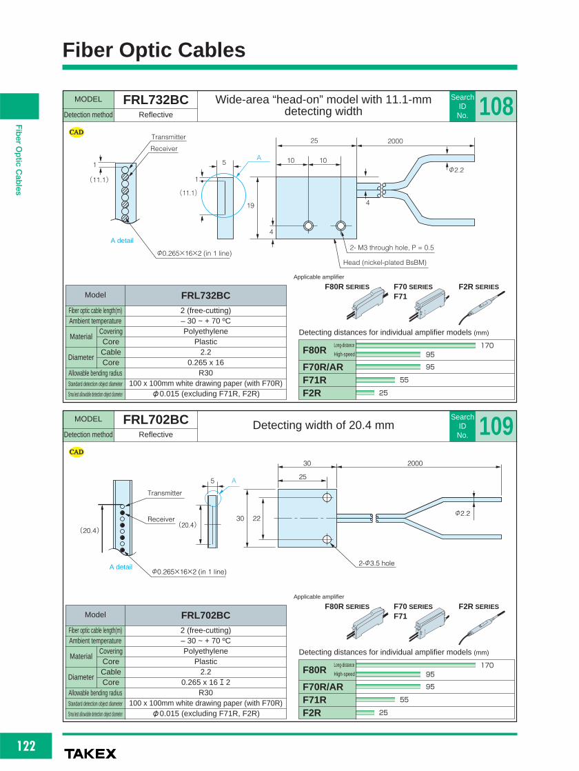
122
FiberOpticCables
Fiber Optic Cables
MODEL FRL732BCDetection method Reflective
Wide-area “head-on” model with 11.1-mmdetecting width
SearchID
No. 108200025
1010
4
19
5A
1
(11.1)
Head (nickel-plated BsBM)
2- M3 through hole, P = 0.5
φ2.2
4
1
(11.1)
φ0.265×16×2 (in 1 line)
Transmitter
Receiver
A detail
MODEL FRL702BCDetection method Reflective
Detecting width of 20.4 mmSearch
ID No. 109
(20.4)
5 A
30
30 22
25
2000
2-φ3.5 hole
φ2.2
Transmitter
Receiver
(20.4)
φ0.265×16×2 (in 1 line)A detail
F80R SERIES F70 SERIES
F71F2R SERIES
Applicable amplifier
F80R SERIES F70 SERIES
F71F2R SERIES
Applicable amplifier
F70R/ARF71RF2R
F80R
Detecting distances for individual amplifier models (mm)
95
17095
55
25
Long-distance
High-speed
F70R/ARF71RF2R
F80R
Detecting distances for individual amplifier models (mm)
95
17095
55
25
Long-distance
High-speed
Model
Fiber optic cable length(m)Ambient temperature
2 (free-cutting)– 30 ~ + 70 ºCPolyethylene
Plastic2.2
0.265 x 16R30
100 x 100mm white drawing paper (with F70R)φ0.015 (excluding F71R, F2R)
Allowable bending radiusStandard detection object diameter
Sma lest allowable detection object diameter
Material
Diameter
CoveringCoreCableCore
FRL732BC
Model
Fiber optic cable length(m)Ambient temperature
2 (free-cutting)– 30 ~ + 70 ºCPolyethylene
Plastic2.2
0.265 x 16 エ 2R30
100 x 100mm white drawing paper (with F70R)φ0.015 (excluding F71R, F2R)
Allowable bending radiusStandard detection object diameter
Sma lest allowable detection object diameter
Material
Diameter
CoveringCoreCableCore
FRL702BC

123
FiberOpticCables
Fiber Optic Cables
MODEL FRLV816BCDetection method Reflective
Cylindrical “wide-area” model with 5.25-mmdetecting width
SearchID No. 110
2 5.25
35 2000
φ2.5φ1.25
A
Transmitter
0.35
5.252
Receiver φ0.265×8×2(0.35 mm pitch, in line)
A detail
MODEL FRLV732BCDetection method Reflective
Side-on model with 11.1-mm detecting widthSearch
ID No. 111
10
2.5
3.5
2.5
2.5
20
4
4A
2- M3 through hole, P = 0.5
Head (nickel-plated BsBM)
1
(11.1)
φ0.265×16×2 (in 1 line)
TransmitterReceiver
2000
φ2.2
A detail
F80R SERIES F70 SERIES
F71F2R SERIES
Applicable amplifier
F80R SERIES F70 SERIES
F71F2R SERIES
Applicable amplifier
F70R/ARF71RF2R
F80R
Detecting distances for individual amplifier models (mm)
95
17095
55
25
Long-distance
High-speed
F70R/ARF71RF2R
F80R
Detecting distances for individual amplifier models (mm)
25
4525
22
10
Long-distance
High-speed
Model
Fiber optic cable length(m)Ambient temperature
2 (free-cutting)– 30 ~ + 70 ºCPolyethylene
Plastic1.25
0.265 x 8 エ 2R15
50 x 50mm white drawing paper (with F70R)φ0.015 (excluding F71R, F2R)
Allowable bending radiusStandard detection object diameter
Sma lest a lowable detec ion object diameter
Material
Diameter
CoveringCoreCableCore
FRLV816BC
Model
Fiber optic cable length(m)Ambient temperature
2 (free-cutting)– 30 ~ + 70 ºCPolyethylene
Plastic2.2
0.265 x 16R4
100 x 100mm white drawing paper (with F70R)φ0.015 (excluding F71R, F2R)
Allowable bending radiusStandard detection object diameter
Sma lest a lowable detec ion object diameter
Material
Diameter
CoveringCoreCableCore
FRLV732BC

124
FiberOpticCables
Fiber Optic Cables
MODEL GLX500J seriesDetection method Reflective
Heat resistance to 200 ºC, covered withfluoroplastic tube
SearchID
No. 113
Values in parentheses show detecting distances for combinations with GXL520J.
Internal toothed washer (8.5 mm O.D., 0.9 mm thick)
Hex nut (7 mm across, 2.4 mm thick)
M4 P=0.7
φ1.1
23
15
φ4.0 φ2.8
L
φ3.1
0.5~0.8
The tightening torque for the threadedpart should be up to 0.8 N・m.
MODEL FX8403BCDetection method Coaxial reflective
M4 screw reflective modelSearch
ID No. 112
The tightening torque for the threadedpart should be up to 0.8 N・m.
M4P=0.7
15
0.5~0.8
5
5 15
φ3.0
2000(φ1.5)
R5.0
φ3.1
φ1.25
φ0.25×9(Receiver)
φ0.5×1(Transmitter)
End face detail
Internal toothed washer (8 5 mm O.D., 0.9 mm thick)
Hex nut (7 mm across, 2.4 mm thick)
専用コネクタ付き
F80R SERIES F70 SERIES
F71F2R SERIES
Applicable amplifier
F80R SERIES F70 SERIES
F71
Applicable amplifier
F70R/ARF71RF2R
F80R
Detecting distances for individual amplifier models (mm)
55
10055
33
10
Long-distance
High-speed
F70R/ARF71R
F80R
Detecting distances for individual amplifier models (mm)
75(70)
135(130)75(70)
45(40)
Long-distance
High-speed
Model
Fiber optic cable length(m)Ambient temperature
2 (free-cutting)– 30 ~ + 70 ºCPolyethylene
Plastic1.25
0.5 x 1 (transmission) / 0.25 x 9 (reception)R15
50 x 50mm white drawing paper (with F70R)φ0.015 (excluding F71R, F2R)
Allowable bending radiusStandard detection object diameter
Sma lest allowable detection object diameter
Material
Diameter
CoveringCoreCableCore
FX8403BC
Model
Fiber optic cable length(m)Ambient temperature
0.5 1 2Tip: – 60 ~ +200 ºC / Covering: 200 ºC
FluoroplasticGlass
2.2Binding diameter: 1.1 (2-section)
R25100 x 100mm white drawing paper (with F70R)
φ0.015 (excluding F71R)
Allowable bending radiusStandard detection object diameter
Sma lest allowable detection object diameter
Material
Diameter
CoveringCoreCableCore
GLX505J GLX510J GLX520J

125
FiberOpticCables
Fiber Optic Cables
MODEL GXH500J seriesDetection method Reflective
Heat resistance to 350 ºC, covered with SS spiral tube
SearchID No. 114
Values in parentheses show detecting distances for combinations with GXL520J.
Internal toothed washer (8.5 mm O.D., 0.9 mm thick)
Hex nut (7 mm across, 2.4 mm thick)
M4 P=0.7
0.5~0.8
φ1.1
23
15
φ4.0φ3.1 φ2.8
L
MODEL GX500J seriesDetection method Reflective
Heat resistance to 230 ºC, M4 screwSearch
ID No. 115
Values in parentheses show detecting distances for combinations with GX510J/520J.
Internal toothed washer (8.5 mm O.D., 0.9 mm thick)
Hex nut (7 mm across, 2.4 mm thick)
M4 P=0.7
0.5~0.8
φ1.1
23
15
φ4.0φ3.1 φ2.8
L
With special connecto
With special connector
F80R SERIES F70 SERIES
F71
Applicable amplifier
F80R SERIES F70 SERIES
F71
Applicable amplifier
F70R/ARF71R
F80R
Detecting distances for individual amplifier models (mm)
75(70)
135(130)75(70)
45(40)
Long-distance
High-speed
F70R/ARF71R
F80R
Detecting distances for individual amplifier models (mm)
75(70)
135(130)75(70)
45(40)
Long-distance
High-speed
The tightening torque for the threadedpart should be up to 0.8 N・m.
The tightening torque for the threadedpart should be up to 0.8 N・m.
Model
Fiber optic cable length(m)Ambient temperature
0.5 1 2– 60 ~ + 350 ºC
SUS spiralGlass
2.8Binding diameter: 1.1 (2-section)
R25100 x 100mm white drawing paper (with F70R)
φ0.015 (excluding F71R)
Allowable bending radiusStandard detection object diameter
Sma lest a lowable detec ion object diameter
Material
Diameter
CoveringCoreCableCore
GXH505J GXH510J GXH520J
Model
Fiber optic cable length(m)Ambient temperature
0.5 1 2Tip: – 60 ~ +230 ºC / Covering: 200 ºC
Silicon tubeGlass
2.8Binding diameter: 1.1 (2-section)
R25100 x 100mm white drawing paper (with F70R)
φ0.015 (excluding F71R)
Allowable bending radiusStandard detection object diameter
Sma lest a lowable detec ion object diameter
Material
Diameter
CoveringCoreCableCore
GX505J GX510J GX520J

126
FiberOpticCables
Fiber Optic Cables
MODEL FRH7BCDetection method Reflective
Lowest-cost heat-resistant fiber optic cable,heat resistance to 105 ºC
SearchID
No. 117
The tightening torque for the threadedpart should be up to 0.8 N・m.
φ2.5
3φ2.2
200017
Internal toothed washer (11 mm O.D., 1.2 mm thick)
Hex nut (8 mm across, 1.5 mm thick)
M6 P=0.75(SUS303)
φ1.0×2
MODEL GXSH5015JDetection method Reflective
M4 screw SS 40 mm, heat resistance to 350 ºCSearch
ID No. 116
(φ1.1)
Bifurcated into semicircles(orientation required)
φ2.11
φ3.0A
A'φ4.0 φ2.8 φ4.0 φ2.2
A
11
(R5.0)
35
Double swaging (φ3+φ2.5)
5 15 M4、P=0.7 15 13
5
23 150 (28)
Do not bend the fiber guide.
A end surface detail
Internal too hed washer (8 5 mm O.D., 0 9 mm thick)
Hex nut (7 mm across, 2.4 mm thick)
M4 P=0.7(SUS303)
The tightening torque for the threadedpart should be up to 0.8 N・m.
F80R SERIES F70 SERIES
F71
Applicable amplifier
F80R SERIES F70 SERIES
F71F2R SERIES
Applicable amplifier
F70R/ARF71R
F80R
Detecting distances for individual amplifier models (mm)
50
9050
30
Long-distance
High-speed
F70R/ARF71RF2R
F80R
Detecting distances for individual amplifier models (mm)
180
320180
100
35
Long-distance
High-speed
Model
Fiber optic cable length(m)Ambient temperature
0.15– 30 ~ + 350 ºC
SUS spiralGlass
2.8Binding diameter: 1.1
R25100 x 100mm white drawing paper (with F70R)
φ0.015 (excluding F71R)
Allowable bending radiusStandard detection object diameter
Sma lest allowable detection object diameter
Material
Diameter
CoveringCoreCableCore
GXSH5015J
Model
Fiber optic cable length(m)Ambient temperature
2 (free-cutting)– 30 ~ + 105 ºC
Heat-resistant polyethylenePlastic
2.21.0R30
200 x 200mm white drawing paper (with F70R)φ0.015 (excluding F71R, F2R)
Allowable bending radiusStandard detection object diameter
Sma lest allowable detection object diameter
Material
Diameter
CoveringCoreCableCore
FRH7BC

127
FiberOpticCables
Fiber Optic Cables
MODEL GTSH seriesGTHDetection method Through-beam
1 x 10⁻⁸ Pa vacuum-proof + heat-resistance to 350 ºCSearch
ID No. 118
● Contact Takex for prices.
(Example of attaching)
Atmosphere side fiber optic cable (FT7VBC-M5)
Light-introducing fiber pin (FA7VP-M5) Lens unit (optional) FA514
Model
Name Vacuum-proof heat-resistant fiber optic cable Light introducing fber pin Atmosphere side iber optic cable
Detection method Through-beam
Copper wire of about φ1
1.2 mm (binding diameter)
500mm, 1000mm
Glass (SUS spiral tube)
– 60 ~ 350 ºC
-- ---- --φ1.5 φ1.5
42mm 2 M (free-cutting)
Glass rod Plastic
--– 30~230ºC – 30~230ºC
40 g max. 25 g max.40 g max. 50 g max.
LeakageAmbient temperature
Mass
Smallest allowable detection objectFiber diameter
LengthMaterial
GTH705V GTSH705VGTH710V GTSH710V
FA7VP-M5 FT7VBC-M5
1 x 10⁻⁸Pa-m3/s(He)
φ4 6 φ3 5
φ8
φ2 927
L2(350°C) L1(200°C)
LO+10
SUS spiral tubeClamping ring
159 2
R10
M4 P=0.7
29 5
17
12
φ3 5
φ2 9820 15 29
L
φ8/M5SUS spiral tubeClamping ring
M4, P0.7
φ12.0φ7 0 φ16 0
φ5.0
14 42
7
1 3
84
1
M5 P=0 8M5 P=0 8
φ7.0
Clamping ring
2000
8
15
φ2.2
10
5
φ7 0
TypeGTSH705V
GTSH710V
L(㎜)500
1000
100
100
400
900
L1(㎜)L2(㎜)
GTSH SeriesType
GTH705V
GTH710V
L(㎜)500
1000
300
800
200
200
L1(㎜)L2(㎜)
GTH Series
Specification
F80R SERIES F70 SERIES
F71
Applicable amplifier
F70R/ARF71R
F80R
Detecting distances for individual amplifier models (mm)
380
680380
220
Long-distance
High-speed

128
FiberOpticCables
Fiber Optic Cables
MODEL GTHN600 seriesDetection method Through-beam
Vacuum-side through-beam M4 screw with M2.6 tip(for flange connection)
SearchID
No. 119
φ3.5
158
L
1648 25.5
φ2.9
φ10
SUS spiral tube
φ10/M8
M4/P0.7
M2.6/P0.45Flange clamping ring with flat surfaces on both sides
MODEL GTHN700 seriesDetection method Through-beam
Vacuum-side through-beam M4 screw (for flange connection)
SearchID
No. 120
φ3 5
158
L
208 25 5
φ2 9
φ10
SUS spiral tube
φ10/M8
M4/P0.7
Flange clamping ring with flat surfaces on both sides
Values in parentheses show detecting distances for combinations with GTHN620V.
Values in parentheses show detecting distances for combinations with GTHN720V.
F80R SERIES F70 SERIES
F71
Applicable amplifier
F80R SERIES F70 SERIES
F71
Applicable amplifier
F70R/ARF71R
F80R
Detecting distances for individual amplifier models (mm)
270(210)
480(380)270(210)
230(170)
Long-distance
High-speed
F70R/ARF71R
F80R
Detecting distances for individual amplifier models (mm)
270(210)
480(380)270(210)
230(170)
Long-distance
High-speed
Model
Fiber optic cable length(m)Ambient temperature
0.5 1 1.5 2– 30 ~ + 350 ºC
SUS spiralGlass
2.9Binding diameter: 1.5
R30φ1.2φ1.0
Allowable bending radiusStandard detection object diameter
Sma lest allowable detection object diameter
Material
Diameter
CoveringCoreCableCore
GTHN605V GTHN610V GTHN615V GTHN620V
Model
Fiber optic cable length(m)Ambient temperature
0.5 1 1.5 2– 30 ~ + 350 ºC
SUS spiralGlass
2.9Binding diameter: 1.5
R30φ1.2φ1.0
Allowable bending radiusStandard detection object diameter
Sma lest allowable detection object diameter
Material
Diameter
CoveringCoreCableCore
GTHN705V GTHN710V GTHN715V GTHN720V

129
FiberOpticCables
Fiber Optic Cables
MODEL GTSHN700 seriesDetection method Through-beam
Vacuum-side through-beam elbow with M4screw (for flange connection)
SearchID No. 121
φ3.5φ2.9
φ4.6
27
L
R10
12
29.5Detecting head
25.5157
M4 P=0.7
SUS spiral tube φ10/M8
Flange clamping ring with flat surfaces on both sides
MODEL GXHN400 seriesDetection method Reflective
Vacuum-side reflective φ4(for flange connection)
SearchID No. 122
φ2.9
φ4φ12φ3.9φ5
5 5
φ3.5Same specification for the branches
Flange side
201.58020L
33
25
15
SUS spiral tube
φ10/M8
Flange clamping ring with flat surfaces on both sides
8
M4/P0.7(OF φ2)
φ4
SUS partition: 0.15 mm thick
Detecting head
Values in parentheses show detecting distances for combinations with GTSHN720V.
F80R SERIES F70 SERIES
F71
Applicable amplifier
F80R SERIES F70 SERIES
F71
Applicable amplifier
F70R/ARF71R
F80R
Detecting distances for individual amplifier models (mm)
270(210)
480(380)270(210)
230(170)
Long-distance
High-speed
F70R/ARF71R
F80R
Detecting distances for individual amplifier models (mm)
35
6035
30
Long-distance
High-speed
Model
Fiber optic cable length(m)Ambient temperature
0.5 1 1.5 2– 30 ~ + 350 ºC
SUS spiralGlass
2.9Binding diameter: 1.5
R30φ1.2φ1.0
Allowable bending radiusStandard detection object diameter
Sma lest a lowable detec ion object diameter
Material
Diameter
CoveringCoreCableCore
GTSHN705V GTSHN710V GTSHN715V GTSHN720V
Model
Fiber optic cable length(m)Ambient temperature
0.5 1– 30 ~ + 350 ºC
SUS spiralGlass
3.9Binding diameter: 2.0 (2-section)
R5050 x 50mm white drawing paper (with F70R)
φ1.0
Allowable bending radiusStandard detection object diameter
Sma lest a lowable detec ion object diameter
Material
Diameter
CoveringCoreCableCore
GXHN405V GXHN410V

130
FiberOpticCables
Fiber Optic Cables
MODEL GXHN700 seriesDetection method Reflective
Vacuum-side reflective with M4 screw (for flange connection)
SearchID
No. 123
φ2.9
φ4φ12φ3.9φ5
5 5
φ3.5
Same specification for the branches
Flange side
20
1.58020L
33
25
22
7
15
SUS spiral tube
φ10/M8
Flange clamping ring with flat surfaces on both sides
8
M4/P0.7(OF φ2)
φ4
SUS partition: 0.15 mm thick
Detecting head
MODEL FA7VG702Detection method ------------
Relay flange 2-ch VG-type φ70Search
ID No. 124
※
※
※
33 40
(4.7)
(4.7)
70
2010
3-φ6.7-hole 120 degrees apartPCD: 58.7 mm
PCD: 20 mm
Atmosphere-side fiber optic cable connection x 4
Vacuum-side fiber optic cable connection x 4
F80R SERIES F70 SERIES
F71
Applicable amplifier
F70R/ARF71R
F80R
Detecting distances for individual amplifier models (mm)
35
6035
30
Long-distance
High-speed
Model
Fiber optic cable length(m)Ambient temperature
0.5 1– 30 ~ + 350 ºC
SUS spiralGlass
5Binding diameter: 2.0
R5050 x 50mm white drawing paper (with F70R)
φ1.0
Allowable bending radiusStandard detection object diameter
Sma lest allowable detection object diameter
Material
Diameter
CoveringCoreCableCore
GXHN705V GXHN710V
Model
FlangeNo. of channels
No. of relaysLeakage
Temperature variationAmbient temperature
MaterialMass
VG-type flange2ch4
1 x 10 –8 Pa・m3/s (He) max.25 ºC/min max.– 30 ~ +250 ºCSUS 304, glass
About 700 g
FA7VG702

131
FiberOpticCables
Fiber Optic Cables
MODEL FA7VG703Detection method ------------
Relay flange 3-ch VG-type φ70Search
ID No. 125
※
※ 5- hole 72 degrees apart
3020
37 40
(4.7)
(4.7)
70
10
※
3-φ6.7 hole 120 degrees apart
Atmosphere-side fiber optic cable connection x 6
Vacuum-side fiber opticcable connection x 6
PCD: 58.7 mm
PCD: 24 mm
MODEL FT7VGBCDetection method ------------
Atmosphere-side free-cutting (for flange connection)
SearchID No. 126
8 28 2000
15
φ10
φ3.5
φ2.2
Flange sideAmplifier side
Flange clamping ring with flat surfaces on both sides(φ10/M8)
Model
FlangeNo. of channels
No. of relaysLeakage
Temperature variationAmbient temperature
MaterialMass
VG-type flange3ch6
1 x 10 –8 Pa・m3/s (He) max.25 ºC/min max.– 30 ~ +230 ºCSUS 304, glass
About 700 g
FA7VG703
Model
Fiber optic cable length(m)Ambient temperature
2-35 ~ + 70 ºCPolyethylene
Plastic2.21.5R30
––
Allowable bending radiusStandard detection object diameter
Sma lest a lowable detec ion object diameter
Material
Diameter
CoveringCoreCableCore
FT7VGBC

132
FiberOpticCables
Fiber Optic Cables
MODEL FL(H) seriesDetection method Dioptric
Applicable to virtually any type of liquid including water, oil,chemicals, etc., heat resistance 200 ºC
SearchID
No. 127Dimensions (in mm) Chemical resistance of PFA (fluoroplastic)
Model
FL(H)-7013FL(H)-7013-02FL-7161FL(H)-7013-05FL-7161-05FL(H)-7013-1FL-7161-1FL(H)-6BCFL-7161-2
PFA length: L Fiber optic cable length: X200 800
200 2300
500 2000
1000 1500
2000 500
Model
FL-7326
FL-7314
PFA diameter Tapered section (*1)
4.0 5
6.35 7
*Unbendable
*2: Can be cut if unnecessary
Heat-resistant
*Unbendable
*2: Can be cut if unnecessary
*1 : Chromatic or achromatic transparent material (be sure to test with a sample in advance for liquid with high
viscosity or turbidity).
*2 : Non-condensing in PFA tube.
○: applicable×: inapplicable
Substance PFA Substance PFA
Bunker A, B, C heavy oilAnilineAcrylic nitrileAsphaltAcetoneAlcoholAmmoniaIsooctaneIsobutyl alcoholIsobutyl methyl ketoneEthanol (ethyl alcohol)EtherEthylene glycolEnamel paintAmmonium chlorideCalcium chlorideSodium chlorideBarium chlorideChlorineGasolineGlass raw materialDilute hydrochloric acidDilute sodium hydroxideDilute acetic acidDilute nitric acidDilute sulfuric acidCitric acidGlycerinCresolChloroformLight oil
○○○○○○○○○○○○○○○○○○○○○○○○○○○○○○○
Mineral oilEthylene trichlorideBichromate of sodaBarium nitrateSilicon oilVegetable oilThinnerBarium hydroxidePhenolTurbine oilSodium carbonateTurpentineNatural volatile oilKeroseneTrichloroethaneTrichloroethyleneTolueneNaphthaLactic acidNitrobenzeneFluorineFerrosiliconFreon 11Propyl alcoholPropylene glycolBenzeneMethanol (methyl alcohol)Methyl violetWaterCarbon tetrachlorideAmmonium sulfate
○○○○○○○○○○○○○○○○○○○○×○○○○○○○○○○
●Example of liquid level detection with 2
liquid level detection fiber optic sensors
Specification
Model
Detection methodDetection objectRepeatability
Withstand pressureAmbient temperature *2Allowable bending radiusFiber optic cable length
DioptricLiquid *1
1 mm max. (for water)– 0.1 MPa ~ +0.5 MPa
– 40 ~ +80 ºC (FL type) / – 40 ~ +100 ºC (FLH type) – 40 ~ +200 ºCR40 mm (50 mm from tip unbendable) R50mm
See “Dimensionsモ” abovePFA
Plastic Glass50g max. 80g max. 150g max.
F80R、F70AR、F70R
Material
MassApplicable amplifier
CoveringFiber optic cable
FL-7161 FL-7161-05 FL-7161-1 FL-7161-2FL-7013 FL-7013-02 FL-7013-05 FL-7013-1 FL-6BC FL-7326FLH-7013 FLH-7013-02 FLH-7013-05 FLH-7013-1 FLH-6BC FL-7314
L X
※1
PFA tubePlastic fiber optic cable (free-cutting)
FL:φ1.25×2FLH:φ1.0×2
50*
φ0 5×5※2
2000 400
※1
1315
(28)PFA tube
Connector50*
φ0 5×5※2
Amplifier for upper limit level
Upper limit leve
Fiber optic cable for liquid level detection
Liquid inlet
Liquid outlet (drain)Water trap
Amplifier for lowelimit level
Lower limit leve
Model
FL seriesFL(H) seriesFL-7161
PFA diameter F ber optic cable diameter Tapered section (*1)6.35 1.25 76.35 1.0 74.0 1.0 5

133
FiberOpticCables
Fiber Optic Cables
MODEL FU901BCDetection method Dioptric
Simple installation requiring no preparationand reliable detection
SearchID No. 128
Specification
Dimensions (in mm)
Mounting
Zip-tie band(provided)
Fiber optic cable(transmitter/ receiver)
Zip-tie band(provided)
Fiber optic cable(transmitter/receiver): A pair for each
Transparent/translucent pipe
φ6~26 mm, pipe wallthickness 3 mm max
φ6~26 mm, pipe wallthickness 3 mm max.
●When two sets ofsensors are used for
upper and lower limit
detection, etc., the
minimum pitch is 15
mm.
Samp Level control with adjacently mounted 2 sets
Transparent or translucent pipe
●●Adjacent mounting allows the minimum pitch of 5 mm
(M3 countersunk screws for assembly are separately required).
Detection object
Applicable pipe
Repeatability
Ambient temperature
Ambient humidity
Allowable bending radius
Fiber optic cable length
Material
Protective structure
Mass
Applicable amplifier
Liquid *1
Transparent pipe of φ6-26 mm
1 mm max.– 40 ~ +105 ºC
35-85%RH
R10 mm (fiber optic cable)
2 m (free-cutting)
Body: polycarbonate Fiber optic cable:
plastic (cross-linked polyethylene-covered)
IP 50
About 7 g
F80R, F70R, F70AR, F71R, F2R
*1:Some types of liquid such as of milky white color may be undetectable.
15 2000
12.6
5
5
5
0.5
15 20
2-φ1

134
FiberOpticCables
Fiber Optic Cables
MODEL FTH7FEBCDetection method Through-beam
Long-distance lens-integrated,heat resistance 115 ºC
SearchID
No. 129
φ5.0φ2.2φ4.0
200022 100
PFA tube
MODEL GTH500FEJDetection method Through-beam
PFA tube covering, heat resistance 200 ºCSearch
ID No. 130
(φ9)
φ6.35φ4.0
φ2.2
(21)
(31.5) L
(L-100) (154.5)
(23)
10 13
A
A'
PFA tube
F80R SERIES F70 SERIES
Applicable amplifier
F80R SERIES F70 SERIES
F71F2R SERIES
Applicable amplifier
F70R/ARF71RF2R
F80R
Detecting distances for individual amplifier models (mm)
1300
23001300
780
230
Long-distance
High-speed
F70R/AR
F80R
Detecting distances for individual amplifier models (mm)
1000
18001000
Long-distance
High-speed
Model
Fiber optic cable length(m)Ambient temperature
2.1– 30 ~ + 105 ºC
Heat-resistant polyethylenePlastic
2.21.0
R40 min.φ4
φ0.03 (excluding F71R, F2R)
Allowable bending radiusStandard detection object diameter
Sma lest allowable detection object diameter
Material
Diameter
CoveringCoreCableCore
FTH7FEBC
Model
Fiber optic cable length(m)Ambient temperature
1 4– 40 ~ + 200 ºC
SUS spiralGlass
2.8Binding diameter: 1.1
R50φ6–
Allowable bending radiusStandard detection object diameter
Sma lest allowable detection object diameter
Material
Diameter
CoveringCoreCableCore
GTH510FEJ GTH540FEJ

135
FiberOpticCables
Fiber Optic Cables
MODEL FRH7FEBCDetection method Reflective
Excellent environment resistanceSearch
ID No. 132
Note) The sensor may stay activated with the maximum sensitivity setting. If this occurs, reduce the sensitivity.
φ6.0
φ2.2
(16)
PFA tube
2000 100
(4.4)
(5.4)
MODEL FTV7FEBCDetection method Through-beam
Through-beam side-viewSearch
ID No. 131
Light axis3
30
2000 30
φ2.2
Detecting head: φ5.0
Note: The 50-mm section from the tip of the detecting head is unbendable.
PFA tube φ4.0
Used as a pair
F80R SERIES F70 SERIES
F71F2R SERIES
Applicable amplifier
F80R SERIES F70 SERIES
F71F2R SERIES
Applicable amplifier
F70R/ARF71RF2R
F80R
Detecting distances for individual amplifier models (mm)
550
990550
400
100
Long-distance
High-speed
F70R/ARF71RF2R
F80R
Detecting distances for individual amplifier models (mm)
70
70
70
35
Long-distance
High-speed130
Model
Fiber optic cable length(m)Ambient temperature
2– 30 ~ + 70 ºC
Heat-resistant polyethylenePlastic
2.21.0
R40 min.φ1.0
φ0.015 (excluding F71R, F2R)
Allowable bending radiusStandard detection object diameter
Sma lest a lowable detec ion object diameter
Material
Diameter
CoveringCoreCableCore
FTV7FEBC
Model
Fiber optic cable length(m)Ambient temperature
2.1– 30 ~ + 105 ºC
Heat-resistant polyethylenePlastic
2.21.0R40
100 x 100mm white drawing paper (with F70R)φ0.015 (excluding F71R, F2R)
Allowable bending radiusStandard detection object diameter
Sma lest a lowable detec ion object diameter
Material
Diameter
CoveringCoreCableCore
FRH7FEBC

136
FiberOpticCables
Fiber Optic Cables
MODEL FU1001BCDetection method Through-beam
Heat resistance 115 ºC,replaceable with photo micro sensor
SearchID
No. 133
MODEL FU1002BCDetection method Through-beam
Heat resistance 115 ºC,replaceable with photo micro sensor
SearchID
No. 134
14.5
26 19
15.5
6.5 9 6.5 10
9
8
19
6.5
13
93.25
3.2511.25
5
6.5
2000
φ1.0
2-φ3.22-φ3.2
Light axis
Head: aluminum (white anodized aluminum)
6.4
19
12.719.3
Light axis
6 3.3
φ2.2 φ1.0
513
3
6.4
26
9
2-φ3.2
Fiber guide (fluoroplastic)
922 2000
10
Head: aluminum (white anodized aluminum)
F80R SERIES F70 SERIES
F71F2R SERIES
Applicable amplifier
F80R SERIES F70 SERIES
F71F2R SERIES
Applicable amplifier
F70R/ARF71RF2R
F80R
Detecting distances for individual amplifier models (mm)
5
5
5
Long-distance
High-speed5}
F70R/ARF71RF2R
F80R
Detecting distances for individual amplifier models (mm)
5
5
5
Long-distance
High-speed5}
Model
Fiber optic cable length(m)Ambient temperature
2 (free-cutting)– 30 ~ 115 ºC (105 ºC max. for continuous use)
Heat-resistant polyethylenePlastic
1.00.5R15φ2
φ0.03 (excluding F71R, F2R)
Allowable bending radiusStandard detection object diameter
Sma lest allowable detection object diameter
Material
Diameter
CoveringCoreCableCore
FU1001BC
Model
Fiber optic cable length(m)Ambient temperature
2 (free-cutting)– 30 ~ +115 ºC (105 ºC max. for continuous use)
Heat-resistant polyethylenePlastic
1.00.5R15φ2
φ0.03 (excluding F71R, F2R)
Allowable bending radiusStandard detection object diameter
Sma lest allowable detection object diameter
Material
Diameter
CoveringCoreCableCore
FU1002BC

137
FiberOpticCables
Fiber Optic Cables
MODEL FU1004BCDetection method Through-beam
Heat resistance 115 ºC, replaceablewith photo micro sensor
SearchID No. 135
MODEL FR706BCDetection method Reflective
Fiber optic cables for 2 channels integratedfor stable detection
SearchID No. 136
26
5
3.5
3
7 7 12
713.6
15.512.6 4.3
4.3
200010.5 10
φ1.0
2-φ3.5
Fiber guide (fluoroplastic)
Head: aluminum (white anodized aluminum)
Light axis
3
8
6203844
101525 2000
φ2.2
4-φ3.2
Ch 2 receiver
Ch 2 transmitter
Ch 1 receiver
Ch 1 transmitter30
Head: aluminum (black anodized aluminum)
F80R SERIES F70 SERIES
F71F2R SERIES
Applicable amplifier
F80R SERIES F70 SERIES
F71
Applicable amplifier
F70R/ARF71RF2R
F80R
Detecting distances for individual amplifier models (mm)
5
5
5
Long-distance
High-speed5}
F70R/ARF71R
F80R
Detecting distances for individual amplifier models (mm)
70
13570
50
Long-distance
High-speed
Model
Fiber optic cable length(m)Ambient temperature
2 (free-cutting)– 30 ~ +115 ºC (105 ºC max. for continuous use)
Heat-resistant polyethylenePlastic
1.00.5R15φ2
φ0.03 (excluding F71R, F2R)
Allowable bending radiusStandard detection object diameter
Sma lest a lowable detec ion object diameter
Material
Diameter
CoveringCoreCableCore
FU1004BC
Model
Fiber optic cable length(m)Ambient temperature
2 (free-cutting)– 30 ~ + 70 ºCPolyethylene
Plastic2.2 x 4
Transmitter: φ1 / Receiver: φ1.5 (for channels 1 and 2)R30
300 mm silicon wafers, etc. (with F70R)φ0.03 (excluding F71R, F2R)
Allowable bending radiusStandard detection object diameter
Sma lest a lowable detec ion object diameter
Material
Diameter
CoveringCoreCableCore
FR706BC

138
FiberOpticCables

Fiber
Optic
Cables
139
Characteristics Tables
Attachments

140
FiberOpticCables
■Directional Characteristics (Typical Example) with F80R
Fiber Optic Cables
FT105BC FT7202BC FT8EBC FT8BC FT81BCFTS8BC FTS5BCFTS88BC FTS53BC
FT108BC FT5BC FT7BCFT3BC FTH7BC
FT19YBC FT5YBC
FTN5BC FTVN5BCFTVN501BC
FTSV5BC FTV7BCFTV74BC
FTSV82BC FTSV73BC FTSV93BC FTL706BC
FTL716BCFTL7165BC
FTVW7YBC FT704BC FTH7FEBC
1200 800 400 0 1200400 800Position (mm)
10001000
20002000
1000
2000
Distance (mm)Distan e (mm)Distance (mm)
Long-distance o g d ta c modemodeLong-distance mode
High-speed g spe d modemodeHigh-speed mode
0 40 8080 40
20002000
30003000
2000
3000
120120Position (mm)
100010001000
Distance (mm)Dis ance (mm)Distance (mm)Long-d stance Long di tance modemodeLong-d stance mode
H gh-speed High-speed modemodeH gh-speed mode
0 80 16080 40Position (mm)
200200
400400
600600
200
400
600D stance (mm)Distance (mm)D stance (mm) Long distance Long-d stance modemodeLong distance mode
High speed High sp ed modemodeHigh speed mode
0 12040 804080120Position (mm)
100100
200200
300300
100
200
300D stance (mm)Dis ance (mm)D stance (mm) Long-distance Long d stance modemodeLong-distance mode
High speed Hig p d modemodeHigh speed mode
600 400 200 0 600200 400Position (mm)
500500
10001000
15001500
500
1000
1500Distance (mm)Distance (mm)Distance (mm)
Long-distance Long distance modeo eLong-distance mode
High speed igh- p d modeo eHigh speed mode
600 400 200 0 600200 400Position (mm)
500500
10001000
15001500
500
1000
1500D stance (mm)Distance mm)D stance (mm)
Long-distance Long distance modem dLong-distance mode
High speed igh- p d modeodeHigh speed mode
0 40 8080 40Position (mm)
200200
100100
300300
200
100
300D stance (mm)Distance mm)D stance (mm)
Long d stance Long di tance modmodeLong d stance mod
High-speed High speed modemodeHigh-speed mode
0 200 400400 200 600600Position (mm)
400400
800800
12001200
400
800
1200Distance (mm)istance (mm)Distance (mm)Long distance Long dis ance modemodeLong distance mode
High-speed H gh speed modemodeHigh-speed mode
150 100 50 0 15050 100
333
Position (mm)
2
111
2
Long-distance Long d tanc modem dLong-distance mode
High-spe d High speed modemodeHigh-spe d mode
Distance Distance (mm)(mm)Distance (mm)
0 40 8080 40 100100Position (mm)
11
2
33
1
2
3
X
Y
X
Y
Long-Lo gdistance is e modeode
Long-distance modeHigh-speed igh p ed
modemodeHigh-speed mode
Distance Distance (mm)(mm)Distance (mm)
0 80
400400
600600
160160 80
400
600
Position (mm)
200200200
800800800
X
Y
X
YDistance (mm)istance (mm)Distance (mm) Long-distance Long-d stance
modemodeLong-distance mode
High-speed Hi h speed modemodeHigh-speed mode
0 80 160160 80Position (mm)
500500
10001000
15001500
500
1000
1500
X
Y
X
Y
D stance (mm)Distance (mm)D stance (mm)
Long-distance L n d st n e modedeLong-distance mode
High-speed igh p e modem dHigh-speed mode
0 40 8080 40Position (mm)
100100
200200
30000
100
200
300
X
Y
X
Y
D stance (mm)istance (mm)D stance (mm)Long distance Long d stance modemodeLong distance mode
High-speed H gh speed m demodeHigh-speed m de
0 80 160160 80Position (mm)
200200
400400
600600
200
400
600
800800800
X
Y
X
Y
Distance (mm)Distance (mm)Distance (mm) L ng d stance Long dis anc modemodeL ng d stance mode
High-speed High- peed modemodHigh-speed mode
0 4 8 12 16 2016 481220Position (mm)
2020
4040
6060
20
40
60
X
Y
X
Y
Distance (mm)Dis a ce (mm)Distance (mm) Long-distance Long distance modemodeLong-distance mode
High-speed High speed modemo eHigh-speed mode
0 80 160160 80Position (mm)
200200
400400
600600
200
400
600
XY
Distance (mm)Dis a ce (mm)Distance (mm)
Long-distance Long-dis ance modemodeLong-distance mode
High speed H gh spe d modemodeHigh speed mode
0 200 400400 200Position (mm)
200200
40000
600600
200
400
600
800800800
XY
D stance (mm)istance (mm)D stance (mm) Long-d stance o g i a c modem dLong-d stance mode
High-speed H g spe d modeo eHigh-speed mode
400
800
1200
1600
200 100 0 100 2000
2000
2400
Position (mm)
X
Y
X
Y
Det
ectin
g di
stan
ce Y
(m
m)
Vertical directionVertical direction
Horizontal l directionHorizontal direction
Long-distance L ng is n modedLong-distance mode
High speed High- peed modemodeHigh speed mode
600 400 200 0 600200 400Position (mm)
200200
400400
600600
200
400
600
800800800D stance (mm)Distance (mm)D stance (mm) Long-Long
distance s n e modeode
Long-distance mode
High-speed High speed modeo eHigh-speed mode
300 200 100 0 300100 200Position (mm)
11
22
33
1
2
3Distance (mm)Distance (mm)Distance (mm)Long distance Long d s nce modemodeLong distance mode
High speed g - pe d modeodeHigh speed mode

141
FiberOpticCables
Fiber Optic Cables■Directional Characteristics (Typical Example) with F80RGLT500J series GTH500J seriesGT500J series
FR105BC FR8EBC FR8BC FRS53BCFRS5BC FRS84BCFRS83BC FRS8BCFR84BC FR83BC
FR5BCFR7BCFRH7BC
FR108BCFR1083BC
FR19YBC FR8YBC
FR5YBCFR7YBC
FXN84BC FXN841BC FRS200J seriesFRS2003J series
FRSV8BCFRSV83BC
FRSV5BCFRSV55BC
FX801BCFX8404BC
FX200J series
FX83BCFX84BCFX8401BC
FX716BC FX7BC
0 200 400400 200 600600Position (mm)
200200
400400
600600
200
400
600
800800800Distance (mm)Distance (mm)Distance (mm)
Long-distance Long d tance modemodeLong-distance mode
High-speed High speed modemo eHigh-speed mode
120 80 40 0 12040 80Position (mm)
600600
40000
200200
600
400
200
D stance (mm)Distance (mm)D stance (mm)
Long-distance Long distance modem dLong-distance mode
High speed High spe d modemodeHigh speed mode
60 40 20 0 6020 40Position (mm)
100100
200200
300300
100
200
300D stance (mm)istance mm)D stance (mm)
Long-distance Long d tan e modemodLong-distance mode
High-speed High peed modem dHigh-speed mode
30 20 10 0 3010 20Position (mm)
5050
100100
150150
50
100
150Distance (mm)istance (mm)Distance (mm)
Long-d stance Long istance modemodeLong-d stance mode
High-speed Hi h peed modemodeHigh-speed mode
30 20 10 0 3010 20Position (mm)
100100
200200
300300
100
200
300
40000400
D stance (mm)Distance (mm)D stance (mm)
Long-distance Long d stance modem deLong-distance mode
High-speed g speed modem dHigh-speed mode
60 40 20 0 6020 40Position (mm)
100100
200200
300300
100
200
300
400400400
D stance (mm)Distance (mm)D stance (mm)
ong-distance Long d st nce modeo e
ong-distance mode
High-speed igh speed modemodeHigh-speed mode
6 4 2 0 62 4Position (mm)
2020
400
6060
20
40
60D stance (mm)Distance mm)D stance (mm)
Long-distance o g is n modeodeLong-distance mode
H gh-speed Hi h p ed modemodeH gh-speed mode
6 4 2 0 62 4Position (mm)
1010
2020
3030
10
20
30D stance (mm)istance mm)D stance (mm)
Long-distance Lo g d ta c modem dLong-distance mode
High-speed High p ed modemodeHigh-speed mode
60 40 20 0 6020 40Position (mm)
100100
200200
300300
100
200
300
D stance (mm)istance (mm)D stance (mm)
Long distance Long dis nce modemodeLong distance mode
High-speed H gh p e modem dHigh-speed mode
15 10 5 0 155 10Position (mm)
6060
2020
4040
60
20
40
Distance (mm)D st nce mm)Distance (mm)
Long-d stance Long distance modeodLong-d stance mode
High-speed igh speed modeo eHigh-speed mode
Both modes Bo h modes (with optimum (w th op mum sensitivity se ting)sen it vit sett ng
Both modes (with optimum sensitivity se ting)
3 2 1 0 31 2Position (mm)
55
1010
1515
5
10
15
Distance (mm)Distance (mm)Distance (mm)
Long-distance ong di tance modem dLong-distance mode
High-speed High-speed modemodHigh-speed mode
6 4 2 0 62 4Position (mm)
1010
2020
300
10
20
30
D stance (mm)ista ce (mm)D stance (mm)
Long-distance Long d tance modem dLong-distance mode
High-speed High speed modem dHigh-speed mode
15 10 5 0 155 10Position (mm)
1010
2020
3030
10
20
30
40040
X
Y
X
Y
D stance (mm)Distance (mm)D stance (mm)Long distance Long d s anc modem deLong distance mode
High-speed High- peed modeo eHigh-speed mode
30 20 10 0 3010 20Position (mm)
5050
100100
150150
50
100
150
X
Y
X
Y
Both modes t e (with opt mum o sensi ivity setting)t y ng
Both modes (with opt mum sensi ivity setting)
Long-distance L ng d tanc modem dLong-distance mode
High-speed igh peed modem dHigh-speed mode
D stance (mm)istance mm)D stance (mm)
60 40 20 0 6020 40Position (mm)
5050
100100
150150
50
100
150
X
Y
D stance (mm)Distance (mm)D stance (mm)
Long-distance Long-d tance modemodLong-distance mode
High speed High- peed modmodeHigh speed mod
60 40 20 0 6020 40Position (mm)
5050
100100
150150
50
100
150
Distance (mm)istance (mm)Distance (mm)
Long distance L n - s n e modemodeLong distance mode
Both modes Both modes (with optimum (w h op mum sensitivity setting)e s t v ty et ng
Both modes (with optimum sensitivity setting)
High-speed High-speed modemodeHigh-speed mode
30 20 10 0 3010 20Position (mm)
500
100100
150150
50
100
150Distance (mm)Dis ance (mm)Distance (mm)
Long-distance o g i a c modeodLong-distance mode
High-speed H gh spe d modem deHigh-speed mode
120 80 40 0 12040 80Position (mm)
200200
40000
600600
200
400
600D stance (mm)Dis a ce (mm)D stance (mm)
Long-d stance Long dista ce modemodLong-d stance mode
High-speed H gh peed modemodeHigh-speed mode
60 40 20 0 6020 40Position (mm)
100100
200200
300300
100
200
300D stance (mm)istance (mm)D stance (mm)
Long-distance L n dist n e modemodeLong-distance mode
High speed High-speed modeo eHigh speed mode

142
FiberOpticCables
Fiber Optic Cables■Directional Characteristics (Typical Example) with F80R
FZ802BC FZ1901YBC
FZV191YBC FRLV816BC FRL732BC FRL702BCFRL7W16BC FRLV732BC
GLX500J seriesGXH500J seriesGX500J series
FZ801BC
15 10 5 0 155 10
XY
Position (mm)
2020
6060
20
60
404040
D stance (mm)Distance mm)D stance (mm)
Long distance modeL g a e m deLong distance modeHigh speed modegh-s e dHigh speed modeLong distance modeLo g- st e mo eLong distance mode
High speed modeg -s eed modeHigh speed mode
Black paperBla k papeBlack paper
White paperWh e pap rWhite paper
FZV8301BC
30 20 10 0 3010 20Position (mm)
2020
4040
6060
20
40
60
XY
Distance (mm)Distance (mm)Distance (mm)Long-d stance Long distance modem dLong-d stance mode
B th mod s Bo h modes (with optimum (w th opt mum sens tiv ty se ting)sen i vit set ng)
B th mod s (with optimum sens tiv ty se ting)
High-speed H gh peed modem dHigh-speed mode
FZV8301BC
2020
4040
6060
20
40
60
30 20 10 0 3010 20Position (mm)
XY
Distance (mm)Distance (mm)Distance (mm)Long-dis ance Long d st nce modem dLong-dis ance mode
Both m des Both modes (w th op imum (wit opt mum sensitivity setting)sensitivity set ing
Both m des (w th op imum sensitivity setting)
High-speed High speed modem dHigh-speed mode
6 4 2 0 62 4Position (mm)
44
88
1212
4
8
12
XY
Dis ance (mm)D st nce (mm)Dis ance (mm)
Black paperBlack paperBlack paper
White paperWhite p perWhite paperLong-d stance modeo g i a c odeLong-d stance mode
Long-d stance modeo g di a c deLong-d stance mode
High-speed modeH g speed o eHigh-speed mode
High-speed modeHigh spe d odeHigh-speed mode
FZ802BC
44
88
1212
4
8
12
6 4 2 0 62 4Position (mm)
XYD stance (mm)Distance mm)D stance (mm)
Black paperBlack paperBlack paper
White paperWh te p perWhite paper
Long distance modeLong-d s ance modeLong distance mode
Long distance modeLong distance modeLong distance mode
High speed High- peed modeo eHigh speed mode
High-speed igh peed modem dHigh-speed mode
6 4 2 0 62 4Position (mm)
5050
100100
150150
50
100
150
XY
D stance (mm)Distance mm)D stance (mm)
Long-distance modeLong distance modeLong-distance modeHigh-speed modeH gh spe m deHigh-speed mode
Long-distance modeLo g distance modeLong-distance modeHigh speed modeig p d m dHigh speed mode
Black pap rB ack papeBlack pap r
Wh te White paperpaperWh te paper
FZ1901YBC
6 4 2 0 62 4Position (mm)
XY
5050
100100
50
100
150150150
Black paperB ac paperBlack paperWhi e paperWhite paperWhi e paper
D stance (mm)Distance (mm)D stance (mm)
Long-d stance modeong-di tance m deLong-d stance modeHigh speed modeH gh- peed modeHigh speed mode
Long-d stance modeLong distance modeLong-d stance modeHigh speed modeHigh- peed m deHigh speed mode
1
2
3
4
-0.8 -0.4 0 0.4 0.80
5
6
7
X
Y
Det
ectin
g di
stan
ce Y
(m
m)
Position X (mm)
FiberFiber
Long-d stance and L ng i n a d high-speed modes h gh speed modes (with optimum (w th opt mum sensitivity setting)sensit vit setting
Long-d stance and high-speed modes (with optimum sensitivity setting)
30 20 10 0 3010 20Position X (mm)
2020
400
6060
20
40
60
808080
X
Y
X
Y
D stance (mm)Di ta e (mm)D stance (mm)
L ng d stance Long-dis ance modemodeL ng d stance mode
High-speed modeHig spe d m dHigh-speed mode
0 20 4040 20Position X (mm)
5050
100100
150150
50
100
150
200200200
X
Y
X
Y
Dis ance (mm)Distance (mm)Dis ance (mm)Long distance o g stan e modeodeLong distance mode
High-speed modeH gh p e mo eHigh-speed mode
60 40 20 0 6020 40Position X (mm)
100100
200200
300300
100
200
300Distance (mm)istance (mm)Distance (mm)
Long-distance L n di t n e modemodeLong-distance mode
High-speed igh peed modem dHigh-speed mode
B th mod s Bo h modes (with optimum w th opt m m sens tiv ty setting)e i i y set ng
B th mod s (with optimum sens tiv ty setting)
FZ801BC
15 10 5 0 155 10Position (mm)
2020
6060
20
60
404040
XY
D stance (mm)istance mm)D stance (mm)
Long-d stance modeLong distance modeLong-d stance mode
Long-d stance modeLo g di ta ce m dLong-d stance modeHigh-speed modeH gh p ed m dHigh-speed mode
High-speed modeHigh speed modeHigh-speed mode
Black pap rB ack paperBlack pap rWhite Wh e paperp pWhite paper
Detection object: transparent glass substrate (t 0.7 mm)

100
0
1
10
×1000
210.5 1.5Distance (m)
Mar
gin
of li
ght i
nten
sity
OperOp rat on eveOperation level
High speed modeHigh-speed modeHigh speed modeong-distan e
mode modeLong d s a ce
mode
100
0
1
10
×1000
421 3Distance (m)
Mar
gin
of li
ght i
nten
sity
OperOpe a i l veOpera ion evel
High-speed modeHigh-speed modeHigh-speed modeLong-distanceLong d stance
mode m deLong-distance
mode
100
0
1
10
×1000
800400200 600Distance (mm)
Mar
gin
of li
ght i
nten
sity
Operpe ation lea ion eveelOperation leve
High sp ed modeHigh spe d modeHigh sp ed modeLong-distanceLong distance
mode modeLong-distance
mode
100
0
1
10
×1000
400200100 300Distance (mm)
Mar
gin
of li
ght i
nten
sity
OperOpe at on lei n e eOperat on leve
High sp ed modeHigh-spe d modeHigh sp ed modeLong d stanceLong-distance
mode modeLong d stance
mode
143
FiberOpticCables
■Distance-Output Characteristics (Typical Example) with F80R
Fiber Optic Cables
FT105BC FT7202BC FT8EBC FT8BC FT81BCFTS8BC FTS5BCFTS88BC FTS53BC
FT108BC FT5BC FT7BCFT3BC FTH7BC
FT19YBC FT5YBC
100
0
1
10
×1000
1000500250 750Distance (mm)
Mar
gin
of li
ght i
nten
sity
OperOpe a ion l v lOperation eve
High peed modeHigh-speed odeHigh peed modeLong-distance
mode modeL ng d stance
mode
100
0
1
10
×1000
1000500250 750Distance (mm)
Mar
gin
of li
ght i
nten
sity
OperOper o le eOpera ion level
High speed modHigh-speed modeHigh speed modLong dis a ceLong-di tance
mode modeLong dis a ce
mode
100
0
1
10
×1000
400200100 300Distance (mm)
Mar
gin
of li
ght i
nten
sity
OperOpe at on ea i n l velOperat on eve
H gh-speed modeHigh speed modeH gh-speed modeLong-distance modeLong distance modeLong-distance mode
100
0
1
10
×1000
1000500250 750Distance (mm)
Mar
gin
of li
ght i
nten
sity
OperOperat on lea i n l velOperat on level
High spe d modHigh-speed modeHigh spe d modLong d s anceLong-distan e
mode modLong d s ance
mode
FTN5BC FTVN5BCFTVN501BC
FTSV5BC FTV7BCFTV74BC
100
0
1
10
×1000
421 3Distance (m)
Mar
gin
of li
ght i
nten
sity
OperO e a ion l v lOperation eve
g High-speed modeg Long-distance
mode modeL ng d s ance
mode
100
0
1
10
×1000
421 3Distance (m)
Mar
gin
of li
ght i
nten
sity
OperOpe a i n l v lOperat on eve
g p High-speed modeg p Long d stanceLong distance
mode modeLong d stance
mode
100
0
1
10
×1000
800400200 600Distance (mm)
Mar
gin
of li
ght i
nten
sity
OperOpe ation ea i n l velOperation evel
H gh- peed m deHigh speed modeH gh- peed m deLong istanceLong d st nce
mode modeLong istance
mode
100
0
1
10
×1000
1000500250 750Distance (mm)
Mar
gin
of li
ght i
nten
sity
OperOp ra ion leon e elOpera ion level
H gh speed modeHigh speed modeH gh speed modeLong d stanceLong di t nce
mode modeLong d stance
mode

144
FiberOpticCables
Fiber Optic Cables■Distance-Output Characteristics (Typical Example) with F80RFTSV82BC FTSV73BC FTSV93BC FTL706BC
FTL716BCFTL7165BC
FTVW7YBC FT704BC
GLT500J seriesGT500J seriesGTH500J series
FR105BC FR8EBC FR8BC FRS53BCFRS5BC FRS84BCFR83BC FRS8BCFR84BC FRS83BC
FR5BCFR7BCFRH7BC
FR108BCFR1083BC
FR19YBC FR8YBC
FR5YBCFR7YBC
FXN84BC FXN841BC FRS200J seriesFRS2003J series
100
0
1
10
×1000
400200100 300Distance (mm)
Mar
gin
of li
ght i
nten
sity
OperOpe a i n vOperat on eve
High-speed modeigh speed modeHigh-speed modeLong di tan e
mode modLong-d stance
mode
100
0
1
10
×1000
800400200 600Distance (mm)
Mar
gin
of li
ght i
nten
sity
OperOpe a on evelOperation level
High- peed modeHigh speed modeHigh- peed modeL ng d s anceLong dist nce
mode modeL ng d s ance
mode
100
0
1
10
×1000
20010050 150Distance (mm)
Mar
gin
of li
ght i
nten
sity
OperOpe at on lea i n lev lOperat on level
High spe d modHigh-speed modeHigh spe d modLong-dis anceLong-distance
m de modeLong-dis ance
m de
100
0
1
10
×1000
400200100 300Distance (mm)
Mar
gin
of li
ght i
nten
sity
OperOp ra ion eti eveleOpera ion evel
H gh speed m deHigh speed modeH gh speed m deLong d s anceLong distance
m de modeLong d s ance
m de
100
0
1
10
×1000
1000500250 750Distance (mm)
Mar
gin
of li
ght i
nten
sity
OperOp on e eOpera ion levelHigh-speed modeHigh speed mo eHigh-speed mode
Long distance mode mode
Long d s a ce mode
100
0
1
10
×1000
421 3Distance (m)
Mar
gin
of li
ght i
nten
sity
OperO e a i n vOperat on eve
High speed modeigh-speed modeHigh speed modeLong d s anceLong distance
mode modeLong d s ance
mode
100
0
1
10
×1000
1000500250 750Distance (mm)
Mar
gin
of li
ght i
nten
sity
OperO erati veOperat on evel
High- peed modeHigh-speed modeHigh- peed modeLong d s a ceLong distance
mode modeLong d s a ce
mode
FTH7FEBC
Distance (m)
×1000
100
10
1
0
Mar
gin
of li
ght i
nten
sity
421 3
OperOpe at on lea i n lev lOperat on leve
Long-dis anceLong i t nce m de mode
Long-dis ance m de
High-speedHigh speed mode mode
High-speed mode
100
0
1
10
×1000
1000500250 750Distance (mm)
Margin of light intensity
OperOpe a i n l v lOperat on eve
High sp ed modeHigh-speed modeHigh sp ed modeLong distance
mode modeLong d s ance
mode
100
0
1
10
×1000
400 800200 600Distance (mm)
Mar
gin
of li
ght i
nten
sity
OperOp ra i n leveOperation evel
High sp d modHigh-speed modeHigh sp d modLong-distanceLong-d s ance
mode modeLong-distance
mode
100
0
1
10
×1000
200 400100 300Distance (mm)
Mar
gin
of li
ght i
nten
sity
OperOpe at on lea i n lev lOperat on level
H gh speed m deHigh-sp ed modeH gh speed m deLong-distance modeLong d s an e modeLong-distance mode
100
0
1
10
×1000
100 20050 150Distance (mm)
Mar
gin
of li
ght i
nten
sity
OperOpe ation ea ion l v lOperation eve
High speed modeHigh speed modeHigh speed modeLong-distance modeLong d stan e modeLong-distance mode
100
0
1
10
×1000
200 400100 300Distance (mm)
Mar
gin
of li
ght i
nten
sity
OperOpe a ion l v lOperation eveHigh-speed modeHigh speed modeHigh-speed mode
Long-distance mode mode
Long-distance mode
100
0
1
10
×1000
200 400100 300Distance (mm)
Mar
gin
of li
ght i
nten
sity
OperOpe a on ev lOperation leveHigh-speed modeHigh speed modeHigh-speed mode
Long distanceLong distance mode mode
Long distance mode
100
0
1
10
×1000
10050Distance (mm)
Mar
gin
of li
ght i
nten
sity
OperOpera i n l veOperation evel
High sp ed modeHigh-spe d modeHigh sp ed modeLong-distanceLong d stance
mode modeLong-distance
mode
100
0
1
10
×1000
402010 30Distance (mm)
Mar
gin
of li
ght i
nten
sity
OperOpe ation ea i n l velOperation eve
High speed modH gh speed modeHigh speed modLong-distanceL ng dis an e
d modeLong-distance
d
100
0
1
10
×1000
200 400100 300Distance (mm)
Mar
gin
of li
ght i
nten
sity
OperOpe a i n l velOperat on evel
High- peed modeH gh-speed modeHigh- peed modeLong dist nce
mode modeLong d s ance
mode
100
0
1
10
×1000
804020 60Distance (mm)
Mar
gin
of li
ght i
nten
sity
OperOpe a i n lev lOperat on level
H gh-speed modeHigh speed modeH gh-speed modeLong-d s anceong di t e
modeLong-d s ance
Both modes Bo h mod s (with optim(w op mum sensit vity se ting)um se s ti i y s t ngBoth modes (with optimum sensit vity se ting)
100
0
1
10
×1000
2010 155Distance (mm)
Mar
gin
of li
ght i
nten
sity
Operpe at on ei n l vellOperat on evel
High sp ed modeH gh-spe d modeHigh sp ed modeLong-dis a ceLong di tance
mode modeLong-dis a ce
mode
100
0
1
10
×1000
402010 30Distance (mm)
Mar
gin
of li
ght i
nten
sity
OperOpe a ion ea i levellOpera ion evel
High speed modeH gh-s eed modeHigh speed modeLong-distanceLong d stance
mod modeLong-distance
mod

145
FiberOpticCables
■Distance-Output Characteristics (Typical Example) with F80RFRSV5BCFRSV55BC
FX801BCFX8404BC
FX200J series
FX83BCFX84BCFX8401BC
FX716BC FX7BC FZ801BC
FZ801BC FZV8301BC FZV8301BC FZ802BC
FZ802BC FZ1901YBC FZ1901YBC FZV191YBC
100
0
1
10
×1000
10050Distance (mm)
Mar
gin
of li
ght i
nten
sity
OperOper n l velOpera ion level
High sp ed modeHigh-speed modeHigh sp ed mode
Both modes Both mod s (with opt m(w th op i um sensi ivity se ting)um sens i y s gBoth modes (with opt mum sensi ivity se ting)
Long-distance modeLong-d s ance modeLong-distance mode
100
0
1
10
×1000
100 20050 150Distance (mm)
Mar
gin
of li
ght i
nten
sity
OperOpe ation ea i l velOperation evel
H gh- peed modeHigh-speed modeH gh- peed modeLong distanceLong distance
mode modeLong distance
mode
100
0
1
10
×1000
200100 15050Distance (mm)
Mar
gin
of li
ght i
nten
sity
OperOpe at on ea i n l v lOperat on eve
High speed m deigh-spe d modeHigh speed m deLong-distanceLong di ta ce
mode modeLong-distance
mode
Bo h modes Both mode (wi h optim(w t op imum sens tivity sett ng)m se i v y set i gBo h modes (wi h optimum sens tivity sett ng)
100
0
1
10
×1000
100 20050 150Distance (mm)
Mar
gin
of li
ght i
nten
sity
OperOpe a ion l v lOperation eve
High speed modHigh speed modeHigh speed modLong-distanceLong-d tance
mode modeLong-distance
mode
100
0
1
10
×1000
200 400100 300Distance (mm)
Mar
gin
of li
ght i
nten
sity
OperOp ra on ev lOperation leve
H g -speed modeHigh-speed modeH g -speed mode Long d s a ceLong distance mode mode
Long d s a ce mode
100
0
1
10
×1000
200 400100 300Distance (mm)
Mar
gin
of li
ght i
nten
sity
OperOp ra ion lea o l veOpera ion level
High s eed modeHigh-speed modeHigh s eed modeLong-d s a ceLong-di tan e
mode modeLong-d s a ce
mode
100
0
1
10
×1000
10020 40 60 80Distance (mm)
Mar
gin
of li
ght i
nten
sity
OperOp ration let on e elOperation leve
High-speed modeHigh speed modeHigh-speed mode Long-distanceL ng dista ce mode m de
Long-distance mode
100
0
1
10
×1000
10020 40 60 80Distance (mm)
Mar
gin
of li
ght i
nten
sity
OperOperat on eveOperation leve
H gh speed m deHigh speed modeH gh speed m de
Long-distanceLong distance mode mo e
Long-distance mode
100
0
1
10
×1000
804020 60Distance (mm)
Mar
gin
of li
ght i
nten
sity
OperOpe ation evelOperation leve
H gh-speed modeHigh-speed modeH gh-speed modeLong-dis anceLong-di ance
mode modeLong-dis ance
mode
100
0
1
10
×1000
804020 60Distance (mm)
Mar
gin
of li
ght i
nten
sity
OperOperation levelOperation leve
High speed m deHigh speed modeHigh speed m deong-distance modeLong dis an e modeong-distance mode
100
0
1
10
×1000
102 4 6 8Distance (mm)
Mar
gin
of li
ght i
nten
sity
OperOpe at on lea i n le elOperat on leve
H gh peed m deHigh-speed modeH gh peed m de ong d s anceLong-dis an e mode mode
ong d s ance mode
100
0
1
10
×1000
102 4 6 8Distance (mm)
Mar
gin
of li
ght i
nten
sity
OperOp ra on eveleOpera ion level
H gh-speed High speed modemodeH gh-speed mode Long d stance
mode modeLong distance
mode
FRLV816BC
100
0
1
10
×1000
804020 60Distance (mm)
Mar
gin
of li
ght i
nten
sity
OperOpe at on ea i n lev lOperat on eve
H gh speed m deHigh sp ed modeH gh speed m deLong-distance
m de modeLong d stance
m de
Both modes Bo h modes (with optim(w op mum sensit vity se ting)um se s i i y s ing)Both modes (with optimum sensit vity se ting)
100
0
1
10
×1000
10020 40 60 80Distance (mm)
Mar
gin
of li
ght i
nten
sity
OperOpera i n l eOperation evel
H gh-speed modeHigh speed modeH gh-speed mode
Long-distanceL ng dis an e d mode
Long-distance d 100
0
1
10
×1000
10020 40 60 80Distance (mm)
Mar
gin
of li
ght i
nten
sity
OperOpe ation ea ion l veOperation evelH gh-speedHigh speed
mode deH gh-speed
mode
Long d s anceLong-distance mode mode
Long d s ance mode
100
0
1
10
×1000
102 4 6 8Distance (mm)
Mar
gin
of li
ght i
nten
sity
Operpe at on ea i n l vellOperat on evel
Long d s ance and high sp ed modesLong-dis an e and h gh spe d mod s(with opt mw h opt mum sensi ivity setting)um sensi i y set ingLong d s ance and high sp ed modes(with opt mum sensi ivity setting)
FRL7W16BC FRL702BCFRL732BC FRLV732BC
GLX500J seriesGXH500J seriesGX500J series
100
0
1
10
×1000
200 400100 300Distance (mm)
Mar
gin
of li
ght i
nten
sity
OperOp rat on eveOperation level
High speed modHigh speed modeHigh speed modLong dis anceLong dist nce
mode modeLong dis ance
mode
100
0
1
10
×1000
100 20050 150Distance (mm)
Mar
gin
of li
ght i
nten
sity
OperOpe at on lea i n levelOperat on level
H gh speed modeHigh-speed modeH gh speed modeLong-distanceLo g-distan e
mode modeLong-distance
mode
Both modes Bo h modes (wi h opt m(wi h optimum sensi ivity setting)um sensi iv y set ingBoth modes (wi h opt mum sensi ivity setting)
Fiber Optic Cables
FRSV8BCFRSV83BC
100
0
1
10
×1000
10050Distance (mm)
Mar
gin
of li
ght i
nten
sity
Operpe i n l v lOperat on level
High-speed modeHigh-speed modeHigh-speed modeLong-distanceLong distance
mode modeLong-distance
mode
Detection object: white drawing paper
Detection object: black drawing paper
Detection object: black drawing paper
Detection object: white drawing paper
Detection object: white drawing paper Detection object: black drawing paper Detection object: transparent glass substrate (t 0.7 mm)
Detection object: white drawing paperDetec ion object: transparent glass substrate (t 0.7 mm)

146
FiberOpticCables
Fiber Optic Cables■Directional Characteristics (Typical Example) with F70R/F70AR
600 600400 400200 200
1000
500
1000
500
0Position (mm)
Distance (mm)istance (mm)Distance (mm)
FT105BC
60 6040 4020 20
10001000
500500
0Position (mm)
15001500D stance (mm)Distance (mm)D stance (mm)
FT7202BC
80 8040 40
200200
100100
0Position (mm)
00300D stance (mm)Dis ance (mm)D stance (mm)
FT8EBC
6080 60 8040 4020 20
100100
5050
0Position (mm)
150150D stance (mm)Distance (mm)D stance (mm)
FT8BC FT81BCFTS8BC FTS5BCFTS88BC FTS53BC
200300 300200100 100
400400
200200
0Position (mm)
600600
Distance (mm)Distance (mm)Distance (mm)
FT108BC
200300 300200100 100
400400
200200
0Position (mm)
600600
Distance (mm)Distance (mm)Distance (mm)
FT5BC FT7BCFT3BC FTH7BC
40 4020 20
100100
0Position (mm)
150
5050
D stance (mm)Distance (mm)D stance (mm)
FT19YBC
200 200 300300 100 100
00400
0Position (mm)
600600
200200
D stance (mm)Distance (mm)D stance (mm)
FT5YBC
100 100 150150 50 500Position (mm)
2
3
1
2
3
1
D stance (mm)istance mm)D stance (mm)
FTN5BC
80 80 100100 40 400Position (mm)
2
3
1
2
3
1
X
Y
X
Y
Distance (mm)Distance (mm)Distance (mm)
FTVN5BCFTVN501BC
300
00
100
300
200
100X
Y
X
Y
400
80 8040 400Position (mm)
D stance (mm)Distance mm)D stance (mm)
FTSV5BC
600
00
00
600
400
200X
Y
X
Y
800
80 8040 400Position (mm)
D stance (mm)Dist nce (mm)D stance (mm)
FTV7BCFTV74BC
150
100
50
150
100
50X
Y
X
Y
40 4020 200Position (mm)
Distance (mm)istance mm)Distance (mm)
FTSV82BC
300
200
100
300
200
100X
Y
X
Y
80 8040 400Position (mm)
400Distance (mm)Distance (mm)Distance (mm)
FTSV73BC
30
20
10
30
20
10X
Y
X
Y
10 108 86 64 42 20Position (mm)
D stance (mm)Distance (mm)D stance (mm)
FTSV93BC
300
200
100
300
200
100XY
80 8040 400Position (mm)
D stance (mm)Dis ance (mm)D stance (mm)
FTL706BC
300
200
100
300
400400
500500
200
100
XY
200 200100 1000Position (mm)
Distance (mm)Distance (mm)Distance (mm)
FTL716BCFTL7165BC
0 5050 100
1200
1000
800
600
400
200
0 100Position X (mm)
Det
ectin
g di
stan
ce L
(m
m)
X X
LL
Horizontal direct on Horizontal direct on Vert cal d rection Vert cal d rection
FTVW7YBC
600
00
00
600
400
200
200300 200 300100 1000Position (mm)
D stance (mm)Distance mm)D stance (mm)
FT704BC
300
200
100
300
200
100
200300 200 300100 1000Position (mm)
400Distance (mm)istance (mm)Distance (mm)
GLT500J series GTH500J seriesGT500J series

147
FiberOpticCables
■Directional Characteristics (Typical Example) with F70R/F70AR
350
300
250
200
50
00
50
350
300
250
200
150
100
50
4060 40 6020 200Position (mm)
D stance (mm)Dist nce (mm)D stance (mm)
FR105BC
2030 20 3010 100Position (mm)
150
100
50
150
100
50
D stance (mm)Distance (mm)D stance (mm)
FR8EBC
1015 10 155 50Position (mm)
60
40
20
60
40
20
D stance (mm)ist nce (mm)D stance (mm)
FR8BC FRS53BCFRS5BC FRS84BCFRS83BC FRS8BCFR84BC FR83BC
4060 20 3020 100Position (mm)
300
200
300
100100
200
D stance (mm)Dist nce (mm)D stance (mm)
FR5BCFR7BCFRH7BC
2030 20 3010 100Position (mm)
300
200
300
100100
200
Distance (mm)Distance (mm)Distance (mm)
FR108BCFR1083BC
23 2 31 10Position (mm)
30
20
30
1010
20
D stance (mm)Dis ance (mm)D stance (mm)
FR19YBC
23 2 31 10Position (mm)
10
5
10
Distance (mm)Distance (mm)Distance (mm)
FR8YBC
2030 20 3010 100Position (mm)
150
050
150
100100
D stance (mm)Distance (mm)D stance (mm)
FR7YBCFR5YBC
1015 10 155 50Position (mm)
60
2020
60
040
80Distance (mm)istance (mm)Distance (mm)
FXN84BC
23 2 31 10Position (mm)
15
55
15
1010
Distance (mm)istance (mm)Distance (mm)
FXN841BC
23 2 31 10Position (mm)
15
55
15
1010
Distance (mm)istance (mm)Distance (mm)
FRS200J seriesFRS2003J series
46 4 62 20Position (mm)
2020
1010
3030
40
XY
X
Y
Distance (mm)Distance (mm)Distance (mm)
FRSV83BCFRSV8BC
2030 20 3010 100Position (mm)
100100
5050
150150
X
Y
X
Y
Distance (mm)Distance (mm)Distance (mm)
2030 20 3010 100Position (mm)
60
0
50
40
30
20
10
60
70
50
40
30
20
10X
Y
D stance (mm)Distance (mm)D stance (mm)
FX801BCFX8404BC
FRSV5BCFRSV55BC
2030 20 3010 100Position (mm)
60
40
20
60
40
20
80Distance (mm)Distance (mm)Distance (mm)
FX200J series
1015 10 155 50Position (mm)
60
40
20
60
40
20
D stance (mm)istance (mm)D stance (mm)
FX83BC FX8401BCFX84BC
4060 40 6020 200Position (mm)
300
200
100
300
200
100
D stance (mm)Dis ance (mm)D stance (mm)
FX716BC
2030 20 3010 100Position (mm)
150
100
0
150
100
50
Distance (mm)Distance (mm)Distance (mm)
FX7BC
1015 10 155 50Position (mm)
XY
XY
7070
6060
5050
4040
3030
2020
1010
Distance (mm)Distance (mm)Distance (mm)
Black paperlack paperBlack paper
White paperWh t p p rWhite paper
FZ801BC
4060 20 3020 100Position (mm)
XY
XY
70
6060
5050
4040
3030
2020
1010
Distance (mm)Distance (mm)Distance (mm)
Black B ack paperp p rBlack paper
White paperW te p pWhite paper
FZV8301BC
Fiber Optic Cables

148
FiberOpticCables
Fiber Optic Cables■Directional Characteristics (Typical Example) with F70R/F70AR
25 2520 201510 5 151050Position (mm)
X
Y
X
Y
150150
100100
5050
Distance (mm)Distance (mm)Distance (mm)
FRL7W16BC
0.8
7
6
5
4
3
2
1
0-0.8 0.4-0.4 0
Detecting position Y (mm)
Det
ectin
g di
stan
ce Z
(m
m)
Y
Z
FiberFiber
FZV191YBC
10 105 50Position (mm)
X
Y
X
Y
30
20
10
30
20
10
D stance (mm)Dist nce (mm)D stance (mm)
FRLV816BC
46 4 62 20Position (mm)
XY
XY
70
60
50
40
30
20
10
70
60
50
40
30
20
10
Distance (mm)istance (mm)Distance (mm)
Black paperBlack paperBlack paper
Wh te paperWhite paperWh te paper
FZ1901YBC
23 2 31 10Position (mm)
XY
XY
7
6
5
4
2
7
6
5
4
3
2
1
D stance (mm)istance (mm)D stance (mm)
Black paperB ack paperBlack paper
White paperh te pa erWhite paper
FZ802BC
25 2520 201510 5 151050Position (mm)
X
Y
X
Y150150
100100
5050
D stance (mm)Distance (mm)D stance (mm)
FRL732BCFRLV732BC
20 20 3030 10 100Position (mm)
150150
100100
5050
D stance (mm)istance (mm)D stance (mm)
GLX500J seriesGXH500J seriesGX500J series
■Distance-Output Characteristics (Typical Example) with F70R/F70AR
Distance (mm)
×1000
100
10
1
0 200 400 600 800 1000
Mar
gin
of li
ght i
nten
sity
Operpe a i n l v lOperat on eve
FT105BC
Distance (mm)
×1000
100
10
1
0 500 1000 1500 2000
Mar
gin
of li
ght i
nten
sity
OperO e a i n l v lOperat on eve
FT7202BC
Distance (mm)
×1000
100
10
1
0 100 200 300 400
Mar
gin
of li
ght i
nten
sity
OperOpe at on lea i n lev lOperat on level
FT8EBC
Distance (mm)
×1000
100
10
1
0 50 100 150 200
Mar
gin
of li
ght i
nten
sity
OperOpe at on ea i n l velOperat on eve
FT8BC FTS5BCFTS8BC FTS53BCFTS88BC FT81BC
Distance (mm)
×1000
100
10
1
0 200 400 600 800
Mar
gin
of li
ght i
nten
sity
OperOpe a i n l v lOperat on evel
FT108BC
Distance (mm)
×1000
100
10
1
0 200 400 600 800
Mar
gin
of li
ght i
nten
sity
OperOpe a i n l v lOperat on evel
FT5BC FT7BCFT3BC FTH7BC
Distance (mm)
×1000
100
10
1
0 50 100 150 200
Mar
gin
of li
ght i
nten
sity
OperOpe at on ei n l vellOperat on evel
FT19YBC
Distance (mm)
×1000
100
10
1
0 200 400 600 800
Mar
gin
of li
ght i
nten
sity
Operpe at on ea i n l veOperat on evel
FT5YBC
Distance (m)
×1000
100
10
1
0 1 2 3 4
Mar
gin
of li
ght i
nten
sity
OperOp r on e eOpera ion level
FTN5BC
Distance (m)
×1000
100
10
1
0 1 2 3 4
Mar
gin
of li
ght i
nten
sity
Operpe a ion ev lOperation leve
FTVN5BCFTVN501BC
Distance (mm)
×1000
100
10
1
0 100 200 300 400
Mar
gin
of li
ght i
nten
sity
OperOp ration leat on eveOperation level
FTSV5BC
Distance (mm)
×1000
100
10
1
0 200 400 600 800 1000
Mar
gin
of li
ght i
nten
sity
OperOperation ea i n l veleOperation evel
FTV7BCFTV74BC

149
FiberOpticCables
Distance (mm)
×1000
100
10
1
0 50 100 150 200
Mar
gin
of li
ght i
nten
sity
Operpe a i n l v lOperat on eve
FTSV82BC
Distance (mm)
×1000
100
10
1
0 100 200 300 400
Mar
gin
of li
ght i
nten
sity
OperOp r t on eveleOperation level
FTSV73BC
Distance (mm)
×1000
100
10
1
0 50 100
Mar
gin
of li
ght i
nten
sity
OperOp ration letion e eOperation level
FTSV93BC
Distance (mm)
×1000
100
10
1
0 10050 200150
Mar
gin
of li
ght i
nten
sity
OperOperat on lea i n l veleOperat on level
FTL706BC
■Distance-Output Characteristics (Typical Example) with F70R/F70AR
Distance (mm)
×1000
100
10
1
0 400200 800600
Mar
gin
of li
ght i
nten
sity
OperOper t n le eOpera ion level
FTL716BCFTL7165BC
Distance (mm)
×1000
100
10
1
0 400200 800600
Mar
gin
of li
ght i
nten
sity
OperOpe ation leon evelelOperation level
FT704BC
Distance (mm)
×1000
100
10
1
0 500 1000
Mar
gin
of li
ght i
nten
sity
Operp a io l eOperation level
FTVW7YBC
Distance (mm)
×1000
100
10
1
0 200100 400300
Mar
gin
of li
ght i
nten
sity
OperOpe ation ea i n l veleOperation evel
GLT500J seriesGT500J seriesGTH500J series
Distance (mm)
×1000
100
10
1
0 200100 400300
Mar
gin
of li
ght i
nten
sity
OperOpe a i n l v lOperat on evel
FR105BC
Distance (mm)
×1000
100
10
1
0 10050 200150
Mar
gin
of li
ght i
nten
sity
OperOp ra ion leon e eOpera ion level
FR8EBC
Distance (mm)
×1000
100
10
1
0 10050 200150
Mar
gin
of li
ght i
nten
sity
OperOpera ion eveOperation level
FR8BC FRS53BCFRS5BC FRS84BCFRS83BC FRS8BCFR84BC FR83BC
Distance (mm)
×1000
100
10
1
0 200100 400300
Mar
gin
of li
ght i
nten
sity
OperOpe ation lea on lev lOperation leve
FR5BC FRH7BCFR7BC
Distance (mm)
×1000
100
10
1
0 200100 400300
Mar
gin
of li
ght i
nten
sity
OperOp ra on evelOperation level
FR108BCFR1083BC
Distance (mm)
×1000
100
10
1
0 2010 4030
Mar
gin
of li
ght i
nten
sity
OperOpe ation ea i n l veOperation evel
FR19YBC
Distance (mm)
×1000
100
10
1
0 2010 4030
Mar
gin
of li
ght i
nten
sity
OperOpera i n eveOperation level
FR8YBC
Distance (mm)
×1000
100
10
1
0 10050 200150
Mar
gin
of li
ght i
nten
sity
OperOperation ea i leveleOperation evel
FR7YBCFR5YBC
Distance (mm)
×1000
100
10
1
0 50 100
Mar
gin
of li
ght i
nten
sity
OperOpe a i n l v lOperat on eve
FXN84BC
Distance (mm)
×1000
100
10
1
0 105 15
Mar
gin
of li
ght i
nten
sity
Operp r t on e eleOperation level
FXN841BC
Distance (mm)
×1000
100
10
1
0 2010 30 40
Mar
gin
of li
ght i
nten
sity
OperOper i n l v lOperat on level
FRS200J seriesFRS2003J series
Distance (mm)
×1000
100
10
1
0 2010 30 40 50
Mar
gin
of li
ght i
nten
sity
OperOpe ation lea on evelOperation level
FRSV8BCFRSV83BC
Fiber Optic Cables

150
FiberOpticCables
Fiber Optic Cables■Distance-Output Characteristics (Typical Example) with F70R, F70AR
■Directional Characteristics (Typical Example) with F71R
Distance (mm)
×1000
100
10
1
0 10050 200150
Mar
gin
of li
ght i
nten
sity
Operpe i n eveOperat on leve
FX716BC
Distance (mm)
×1000
100
10
1
0 10050 200150
Mar
gin
of li
ght i
nten
sity
Operpe a ion vOperation eve
FX7BC
Distance (mm)
×1000
100
10
1
0 50 100
Mar
gin
of li
ght i
nten
sity
OperOpe at on lea i n lev lOperat on level
FZ801BC
FZ802BC FZ1901YBC FZV191YBC
Distance (mm)
×1000
100
10
1
0 40 60 8020 100
Margin of light intensity
OperOpe ation leat on eveleOperation level
FZV8301BC
Distance (mm)
×1000
100
10
1
0 100 15050 200
Mar
gin
of li
ght i
nten
sity
OperO era i n l veOperat on evel
Distance (mm)
×1000
100
10
1
0 4 62 8 10
Mar
gin
of li
ght i
nten
sity
Operpe i n l veOperat on evel
Distance (mm)
×1000
100
10
1
0 40 6020 80 100
Mar
gin
of li
ght i
nten
sity
Operpera i n l veOperat on evel
Distance (mm)
×1000
100
10
1
0 2 4 6 8 10
Mar
gin
of li
ght i
nten
sity
Operpe ation leio eOperation level
ansparent glass substranspar nt g ass su st ate te (t = 0.7 mm)(t 0 7 mTransparent glass substrate (t = 0.7 mm)
FRLV816BC
Distance (mm)
×1000
100
10
1
0 20 3010 40
Mar
gin
of li
ght i
nten
sity
Operp ration lea ion evelOperation leve
FRL7W16BC
Distance (mm)
×1000
100
10
1
0 100 15050 200
Mar
gin
of li
ght i
nten
sity
Operpe a ion ev lOperation leve
FRL732BCFRLV732BC
Distance (mm)
×1000
100
10
1
0 100 15050 200
Mar
gin
of li
ght i
nten
sity
OperOpe i n l vellOperat on level
GLX500J seriesGXH500J seriesGX500J series
1000
00
1000
500
400600 200 400 6002000Position (mm)
D stance (mm)Distance mm)D stance (mm)
FT105BC
60 6040 4020 200Position (mm)
15001500
10001000
500500
D stance (mm)Distance (mm)D stance (mm)
FT7202BC
80 8040 400Position (mm)
300300
200200
100100
D stance (mm)Dis ance (mm)D stance (mm)
FT8EBC
80 8040 402020 6060 0Position (mm)
150150
100100
5050
Distance (mm)Distance (mm)Distance (mm)
FT8BC FT81BCFTS8BC FTS5BCFTS88BC FTS53BC
Distance (mm)
×1000
100
10
1
0 50 100
Mar
gin
of li
ght i
nten
sity
OperOpe a i n lev lOperat on level
FRSV5BCFRSV55BC
Distance (mm)
×1000
100
10
1
0 50 100
Mar
gin
of li
ght i
nten
sity
OperOpe a on lev lOperation leve
FX801BCFX8404BC
Distance (mm)
×1000
100
10
1
0 50 100
Mar
gin
of li
ght i
nten
sity
Operpe ation lea ion ev lOperation leve
FX200J series
Distance (mm)
×1000
100
10
1
0 20 40 60 80 100
Mar
gin
of li
ght i
nten
sity
OperOp ra ion lea on elOpera ion level
FX83BC FX8401BCFX84BC

151
FiberOpticCables
■Directional Characteristics (Typical Example) with F71R
40 4020 200Position (mm)
150150
100100
5050
X
Y
X
Y
D stance (mm)ista ce (mm)D stance (mm)
FTSV82BC
80 8040 400Position (mm)
300300
200200
100100
X
Y
X
Y
400D stance (mm)istance (mm)D stance (mm)
FTSV73BC
10 108 86 64 42 20Position (mm)
1515
1010
55
X
Y
X
Y
Distance (mm)Distance (mm)Distance (mm)
FTSV93BC
40 4020 200Position (mm)
150150
100100
5050XY
D stance (mm)istance (mm)D stance (mm)
FTL706BC
200 200100 1000Position (mm)
XY
500500
300300
00400
100100
200200
D stance (mm)Distance (mm)D stance (mm)
FTL716BCFTL7165BC
200300 300200100 1000Position (mm)
600600
00400
200200
Distance (mm)Distanc mm)Distance (mm)
FT704BC
200300 300200100 1000Position (mm)
300300
200200
100100
D stance (mm)ista ce (mm)D stance (mm)
GLT500J seriesGT500J seriesGTH500J series
4060 604020 200Position (mm)
00300
200200
100100
5050
50350
250250
150150
D stance (mm)Distance mm)D stance (mm)
FR105BC
2030 302010 100Position (mm)
100100
5050
150150D stance (mm)Dis ance (mm)D stance (mm)
FR8EBC
1015 15105 50Position (mm)
4040
2020
060
D stance (mm)Distance (mm)D stance (mm)
FR8BC FRS53BCFRS5BC FRS84BCFRS83BC FRS8BCFR84BC FR83BC
4060 302020 100Position (mm)
200200
100100
300300Distance (mm)Distance (mm)Distance (mm)
FR5BC FRH7BCFR7BC
200 200100100 300300 0Position (mm)
300300
200200
100100
400D stance (mm)Distance (mm)D stance (mm)
FT108BC
200 200100100 300300 0Position (mm)
300300
200200
100100
400Distance (mm)Distance (mm)Distance (mm)
FT5BC FT7BCFT3BC FTH7BC
40 402020 0Position (mm)
100
50
100
50
150D stance (mm)Distance mm)D stance (mm)
FT19YBC
200300 200 300100100 0Position (mm)
600
200
600
200
00400
D stance (mm)Distance (mm)D stance (mm)
FT5YBC
50100 50 1002525 0Position (mm)
22
11
Distance (mm)Dis ance (mm)Distance (mm)
FTN5BC
60 6040 4020 200Position (mm)
1 51.5
11
0 50.5
X
Y
X
YD stance (mm)Distance mm)D stance (mm)
FTVN5BCFTVN501BC
80 8040 400Position (mm)
300300
200200
100100
X
Y
X
Y
400D stance (mm)Distance (mm)D stance (mm)
FTSV5BC
40 4020 200Position (mm)
300300
200200
100100
X
Y
X
Y
400D stance (mm)Dis ance (mm)D stance (mm)
FTV7BCFTV74BC
Fiber Optic Cables

152
FiberOpticCables
Fiber Optic Cables■Directional Characteristics (Typical Example) with F71R
2030 302010 100Position (mm)
6060
7070
5050
4040
3030
2020
1010X
Y
X
Y
Distance (mm)D stance (mm)Distance (mm)
FRSV5BCFRSV55BC
2030 302010 100Position (mm)
6060
7070
5050
4040
3030
2020
1010X
Y
D stance (mm)istance (mm)D stance (mm)
FX801BCFX8404BC
2030 302010 100Position (mm)
6060
80
040
2020
D stance (mm)Distance (mm)D stance (mm)
FX200J series
1015 15105 50Position (mm)
6060
040
2020
D stance (mm)Dist nce (mm)D stance (mm)
FX83BC FX8401BCFX84BC
4060 604020 200Position (mm)
150150
100100
5050
Distance (mm)Distanc (mm)Distance (mm)
FX716BC
2030 302010 100Position (mm)
150150
100100
5050
D stance (mm)Dis ance (mm)D stance (mm)
FX7BC
1015 15105 50Position (mm)
7070
6060
XY
Y X
5050
4040
3030
2020
1010
D stance (mm)Dis ance (mm)D stance (mm)
B ack paperl k p p rB ack paper
White paperWh te p p rWhite paper
FZ801BC
23 2 31 10Position (mm)
XY
XY
7
6
4
3
2
7
6
5
4
3
2
1
D stance (mm)Distance (mm)D stance (mm)
B ack aperBla k paperB ack aper
White paperWhi e papeWhite paper
FZ802BC
46 4 62 20Position (mm)
XY
XY
70
60
0
40
30
20
10
70
60
50
40
30
20
10
D stance (mm)Distance (mm)D stance (mm)
Black paperB ack pap rBlack paper
Whi e paperWh te paperWhi e paper
FZ1901YBC
10 105 50Position (mm)
X
Y
X
Y
30
20
10
30
20
10
Distance (mm)Dis ance (mm)Distance (mm)
FRLV816BC
4060 302020 100Position (mm)
7070
6060
XY
Y X
5050
040
3030
2020
1010
D stance (mm)Dis ance (mm)D stance (mm)
Black Black paperpaperBlack paper
White paperWh te paperWhite paper
FZV8301BC
20 202525 15 1510 105 50Position (mm)
150150
Y
X
100100
5050
Distance (mm)Distance (mm)Distance (mm)
FRL7W16BC
2030 302010 100Position (mm)
200200
100100
300300D stance (mm)ista ce (mm)D stance (mm)
FR108BCFR1083BC
23 321 10Position (mm)
2020
1010
3030Distance (mm)istance (mm)Distance (mm)
FR19YBC
23 321 10Position (mm)
1010
55
D stance (mm)istance (mm)D stance (mm)
FR8YBC
2030 302010 100Position (mm)
150150
100100
5050
D stance (mm)istance (mm)D stance (mm)
FR7YBCFR5YBC
1015 15105 50Position (mm)
3030
2020
1010
D stance (mm)Distance mm)D stance (mm)
FXN84BC
23 321 10Position (mm)
1515
1010
55
D stance (mm)istance (mm)D stance (mm)
FXN841BC
23 321 10Position (mm)
1515
1010
55
Distance (mm)istance (mmDistance (mm)
FRS200J seriesFRS2003J series
46 642 20Position (mm)
030
2020
1010
40
X
Y
X
Y
D stance (mm)ist nce (mm)D stance (mm)
FRSV8BCFRSV83BC

153
FiberOpticCables
■Directional Characteristics (Typical Example) with F71R
Distance (m)
×1000
100
10
1
0 1 2 3 4
Mar
gin
of li
ght i
nten
sity
OperOpe a i n l velOpera ion evel
FTN5BC
Distance (m)
×1000
100
10
1
0 1 2 3 4
Mar
gin
of li
ght i
nten
sity
OperOpe a ion l v lOperation eve
FTVN5BCFTVN501BC
Distance (mm)
×1000
100
10
1
0 50 100 150 200
Mar
gin
of li
ght i
nten
sity
OperOpe a i n ev lOperat on leve
FTSV5BC
Distance (mm)
×1000
100
10
1
0 100 100 300 400 500
Mar
gin
of li
ght i
nten
sity
Operpe at on lea i n eveelOperat on leve
FTV7BCFTV74BC
Distance (mm)
×1000
100
10
1
0 50 100 150 200
Mar
gin
of li
ght i
nten
sity
OperOpe a i n l v lOperat on eve
FTSV82BC
Distance (mm)
×1000
100
10
1
0 100 200 300 400
Mar
gin
of li
ght i
nten
sity
Operp ration evelOperation leve
FTSV73BC
Distance (mm)
×1000
100
10
1
0 50 100
Mar
gin
of li
ght i
nten
sity
Operp r io eOperation level
FTSV93BC
Distance (mm)
×1000
100
10
1
0 50 100 150 200
Mar
gin
of li
ght i
nten
sity
OperOpera ion leon e eleOpera ion level
FTL706BC
■Distance-Output Characteristics (Typical Example) with F71R
20 202525 15 1510 105 50Position (mm)
150150
Y
Y
X
100100
5050
Y
X
D stance (mm)Dist nce (mmD stance (mm)
FRL732BCFRLV732BC
20 20 3030 10 100Position (mm)
150150
100100
5050
Distance (mm)Dis anc (mm)Distance (mm)
GLX500J seriesGXH500J seriesGX500J series
Distance (mm)
×1000
100
10
1
0 200 400 600 800 1000
Mar
gin
of li
ght i
nten
sity
OperOpe a i n evelOperat on level
FT105BC
Distance (mm)
×1000
100
10
1
0 200 400 600 800 1000
Mar
gin
of li
ght i
nten
sity
OperOpe a i n e elOperat on leve
FT7202BC
Distance (mm)
×1000
100
10
1
0 100 200 300 400
Mar
gin
of li
ght i
nten
sity
OperOperation lea i n evelOperation level
FT8EBC
Distance (mm)
×1000
100
10
1
0 50 100 150 200
Mar
gin
of li
ght i
nten
sity
OperOperation ea i n le elOperation evel
FT8BC FTS5BCFTS8BC FTS53BCFTS88BC FT81BC
Distance (mm)
×1000
100
10
1
0 200 400 600 800
Mar
gin
of li
ght i
nten
sity
OperOpe t n l velOpera ion level
FT108BC
Distance (mm)
×1000
100
10
1
0 100 200 300 400
Mar
gin
of li
ght i
nten
sity
OperOpe a i n levellOperat on level
FT5BC FT7BCFT3BC FTH7BC
Distance (mm)
×1000
100
10
1
0 50 100 150 200
Mar
gin
of li
ght i
nten
sity
OperOpe ation lea o evOperation leve
FT19YBC
Distance (mm)
×1000
100
10
1
0 200 400 600 800
Mar
gin
of li
ght i
nten
sity
OperOpe at on lea i n lev lOperat on level
FT5YBC
Fiber Optic Cables

154
FiberOpticCables
Fiber Optic Cables■Distance-Output Characteristics (Typical Example) with F71R
Distance (mm)
×1000
100
10
1
0 200 400 600 800
Mar
gin
of li
ght i
nten
sity
OperOp ra ion evelOperation leve
FTL716BCFTL7165BC
Distance (mm)
×1000
100
10
1
0 200 400 600 800
Mar
gin
of li
ght i
nten
sity
OperOp a on evelOperation level
FT704BC
Distance (mm)
×1000
100
10
1
0 100 200 300 400
Mar
gin
of li
ght i
nten
sity
OperOp ration lea ion ev lOperation leve
GLT500J seriesGT500J seriesGTH500J series
Distance (mm)
×1000
100
10
1
0 100 200 300 400
Mar
gin
of li
ght i
nten
sity
OperOpe a i n levelOperation evel
FR105BC
Distance (mm)
×1000
100
10
1
0 50 100 150 200
Mar
gin
of li
ght i
nten
sity
OperOp rat on e eOperation level
FR8EBC
Distance (mm)
×1000
100
10
1
0 20 40 60 80 100
Mar
gin
of li
ght i
nten
sity
OperOpe at on lea i n lev lOperat on leve
FR8BC FRS53BCFRS5BC FRS84BCFRS83BC FRS8BCFR84BC FR83BC
Distance (mm)
×1000
100
10
1
0 50 100 150 200
Mar
gin
of li
ght i
nten
sity
OperOpera ion en l vellOpera ion evel
FR5BC FRH7BCFR7BC
Distance (mm)
×1000
100
10
1
0 50 100 150 200
Mar
gin
of li
ght i
nten
sity
OperOpe a on lev lOperation level
FR108BCFR1083BC
Distance (mm)
×1000
100
10
1
0 10 20 30 40
Mar
gin
of li
ght i
nten
sity
OperOpe at on lev lOperation leve
FR19YBC
Distance (mm)
×1000
100
10
1
0 5 10 15 20
Mar
gin
of li
ght i
nten
sity
OperOp ration lea on e eOperation level
FR8YBC
Distance (mm)
×1000
100
10
1
0 50 100 150 200
Mar
gin
of li
ght i
nten
sity
OperOp ration lea ion eveelOperation leve
FR7YBCFR5YBC
Distance (mm)
×1000
100
10
1
0 20 40 60 10080
Mar
gin
of li
ght i
nten
sity
Operpe a ion evelOperation leve
FXN84BC
Distance (mm)
×1000
100
10
1
0 5 10 15
Mar
gin
of li
ght i
nten
sity
OperOpe ation leat on e elOperation leve
FXN841BC
Distance (mm)
×1000
100
10
1
0 10 20 30 40
Mar
gin
of li
ght i
nten
sity
OperOp rat on e eleOperation level
FRS200J seriesFRS2003J series
Distance (mm)
×1000
100
10
1
0 10 20 30 40 50
Mar
gin
of li
ght i
nten
sity
Operpe at on lea i n evelOperat on leve
FRSV8BCFRSV83BC
Distance (mm)
×1000
100
10
1
0 50 100
Mar
gin
of li
ght i
nten
sity
Operpe a i n evelOperat on level
FRSV5BCFRSV55BC
Distance (mm)
×1000
100
10
1
0 50 100
Mar
gin
of li
ght i
nten
sity
OperOpe ion evelOperation level
FX801BCFX8404BC
Distance (mm)
×1000
100
10
1
0 20 40 60 80 100
Mar
gin
of li
ght i
nten
sity
OperOp ration leation e elOperation leve
FX200J series
Distance (mm)
×1000
100
10
1
0 20 40 60 80 100
Mar
gin
of li
ght i
nten
sity
OperOpe ation ea ion l v lOperation eve
FX83BC FX8401BCFX84BC

155
FiberOpticCables
■Distance-Output Characteristics (Typical Example) with F71R
Distance (mm)
×1000
100
10
1
0 50 100 150 200
Mar
gin
of li
ght i
nten
sity
OperOperat on eation levelelOperat on evel
FRL7W16BC
Distance (mm)
×1000
100
10
1
0 50 100 150 200
Mar
gin
of li
ght i
nten
sity
OperOpe i n l v lOperat on level
FRL732BCFRLV732BC
Distance (mm)
×1000
100
10
1
0 50 100 150 200
Mar
gin
of li
ght i
nten
sity
OperOpe a i n l v lOperat on evel
GLX500J seriesGXH500J seriesGX500J series
Distance (mm)
×1000
100
10
1
0 50 100 150 200
Mar
gin
of li
ght i
nten
sity
OperOp ration leation evelOperation leve
FX716BC
Distance (mm)
×1000
100
10
1
0 20 40 60 80 100
Mar
gin
of li
ght i
nten
sity
OperOpe a on ev lOperation leve
FX7BC
Distance (mm)
×1000
100
10
1
0 50 100
Mar
gin
of li
ght i
nten
sity
Operpe ion e elOperation leve
FZ801BC
Distance (mm)
×1000
100
10
1
0 4 62 8 10
Mar
gin
of li
ght i
nten
sity
OperOpe a on evelOperation level
FZ802BC
Distance (mm)
×1000
100
10
1
0 40 6020 80 100
Mar
gin
of li
ght i
nten
sity
OperOpe a ion l v lOperation eve
FZ1901YBC
Distance (mm)
×1000
100
10
1
0 20 3010 40
Mar
gin
of li
ght i
nten
sity
OperOpe at on lea i n l v lOperat on level
FRLV816BC
Distance (mm)
×1000
100
10
1
0 20 40 60 80 100
Mar
gin
of li
ght i
nten
sity
OperOpe ation leo le lOperation level
FZV8301BC
Fiber Optic Cables

156
FiberOpticCables
Fiber Optic Cables■Directional Characteristics (Typical Example) with F2R
10 10 1515 5 50Position (mm)
45545
40040
35535
30030
252525
20020
15515
10010
55
DistanceDi tDistance(mm)
40 4020 200Position (mm)
1404140
1202120
1000100
808080
60660
40040
202020
Distancei( )
Distance(mm)
4 42 20Position (mm)
141414
16616
12212
10010
88
66
44
22
DistanceD st ncm
Distance(mm)
4 42 20Position (mm)
141414
16616
121212
10010
88
66
44
22
DistanceDis nceDistance(mm)
FT8BC FTS5BCFTS8BC FTS53BCFTS88BC
FT7BCFTH7BCFT5BC
FR8BC FRS83BCFR83BC FRS84BCFR84BC FRS5BCFRS8BC FRS53BC
FX83BCFX84BC
10 105 50Position (mm)
454545
40440
353535
30330
252525
202020
1515
10010
55
D stanceDist ncD stance(mm)
10 105 50Position (mm)
454545
40040
35335303030
252525
202020
15515
10010
55
D stanceDist ncD stance(mm)
10 105 50Position (mm)
454545
40040
35335
30030
252525
202020
15515
10010
55
DistanceDis nceDistance(mm)
40 10 20 30 4030 20 10 0Position (mm)
1808180
1606160
140140140
1202120
1000100
80080
60060
40040202020
DistanceD stance(mm
Distance(mm)
Horizontal Ho i o tal directionr ioHorizontal direction
Vertical Vert ca directione onVertical direction
FR7BCFR5BC
FRH7BC FX7BC FTV74BCFTV7BC
40 10 20 30 4030 20 10 0Position (mm)
140140
1202120
1000100
80080
60660
40040
202020
Horizontal Ho i ont directiond e nHorizontal direction
Vertical e a directiond re t onVertical direction
DistanceD s ance(mm
Distance(mm)
20 5 10 15 2015 10 5 0Position (mm)
808080
707070
606060
303030
202020
101010
505050
505050
DistanceD s ance(mm
Distance(mm)
Horizon al Hor zon l directiond c nHorizon al direction
Vertica Vert al directiond e nVertica direction
4 1 2 3 43 2 1 0Position (mm)
161616
14414
121212
66
44
22
88
1010
Hor zontal H i n directiond ect oHor zontal directionVer ica V i l directiond ect oVer ica direction
DistanceistanceDistance(mm)
8 2 4 6 86 4 2 0Position (mm)
30030
252525
10010
55
15515
20220
D stanceDi ance( m
D stance(mm)
FTSV5BC FTSV73BC FRSV5BCFRSV55BC
FTSV82BC
4 1 2 3 43 2 1 0Position (mm)
77
66
33
22
11
44
55
DistanceDistance( m)
Distance(mm)
FRSV83BC

157
FiberOpticCables
■Distance-Output Characteristics (Typical Example) with F2R
Distance (mm)
×400300200
100
50
20
10
5
2
1
0 10 20 30 40 50
Mar
gin
of li
ght
inte
nsity
e o vOperation level
Distance (mm)
×400300200
100
50
20
10
5
2
1
0 20 40 60 80 100 120 140
Mar
gin
of li
ght
inte
nsity
e o eOperation level
Distance (mm)
×400300200
100
50
20
10
5
2
1
0 2 4 6 8 10 12 14
Mar
gin
of li
ght
inte
nsity
e eOperation level
Distance (mm)
×100
50
20
10
5
2
1
0 2 4 6 8 10 12 14
Mar
gin
of li
ght
inte
nsity
p t eOperation level
FT8BC FTS5BCFTS8BC FTS53BCFTS88BC
FT7BCFTH7BCFT5BC
FR8BC FRS8BC FRS5BCFR83BC FRS83BC FRS53BCFR84BC FRS84BC
FX83BCFX84BC
Distance (mm)
×400300200
100
50
20
10
5
2
1
0 10 20 30 40 50
Mar
gin
of li
ght
inte
nsity
p r n lOperation level
Distance (mm)
×400300200
100
50
20
10
5
2
1
0 10 20 30 40 50
Mar
gin
of li
ght i
nten
sity
e n eOperation level
Distance (mm)
×400300200
100
50
20
10
5
2
1
0 10 20 30 40 50 60
Mar
gin
of li
ght
inte
nsity
e n eOperation level
Distance (mm)
×200
100
50
20
10
5
2
1
0 20 40 60 80 100 120 140
Mar
gin
of li
ght
inte
nsity
r n velOperation leve
FX7BC FRH7BC FR7BC FTSV73BC
Distance (mm)
×200
100
40
20
10
4
2
1
0 20 40 60 80 100 120 140
Mar
gin
of li
ght
inte
nsity
r n lOperation leve
Distance (mm)
×100
40
20
10
4
2
1
0 10 20 30 40
Mar
gin
of li
ght
inte
nsity
r n v lOperation leve
Distance (mm)
100
×200
40
20
10
4
2
1
0 4 8 12 1618 202 6 10 14
Mar
gin
of li
ght
inte
nsity
p r i n v lOperat on level
Distance (mm)
×100
40
20
10
4
2
1
0 4 82 6 10
Mar
gin
of li
ght
inte
nsity
r n lOperation leve
FTSV5BC FTSV82BC FRSV5BCFRSV55BC
FTSV83BC
Distance (mm)
100
×200
40
20
10
4
2
1
0 80 14040 100 180 220
Mar
gin
of li
ght
inte
nsity
r n lOperation level
FTV74BCFTV7BC
Fiber Optic Cables

158
FiberOpticCables
Fiber Optic Cables
Fiber
φ4φ6
6 9
15 (8~12)
Lens Body: aluminum(black anodized aluminum)
Secure with nut and washer provided with fiber optic cable, etc.
(With lens attached to transmitter and receiver)
■Attachments
Type/Model Description Dimensions (mm) Remarks
Lens
unit
FA714
FA814
形式・FA514
FA205
FA200
FA240
●For fiber optic cablewith two-tiered screwAnd M2.6 tip
●Does not apply toreflective types
●For fiber optic cableswith M3, 0.5 mm-pitch screw
●Does not apply toreflective types
●For through-beamfiber optic cables withM4, 0.7 mm-pitchscrew
●Does not apply toreflective types
● Increases sensingdistance by 10 times(with φ1.0 fiber opticcable core)
●For through-beamfiber optic cables withM4, 0.7 mm-pitchscrew
● Increases sensingdistance by 20 times(with φ1.0 fiber opticcable core)
●For coaxial reflectivefiber optic cables withM4, 0.7 mm-pitchscrew
Fiber optic cable
FT7BC
FTH7BC
3400
3400
1900
1900
1900
1900
F71R
1150
1150
F2R
500
500
Also applicable to fiber opticcables with φ0.5, 1.0 or 1.5 core.
Also applicable to fiber opticcables with φ0.5, 1.0 or 1.5 core.
Applicable fiber
optic cable:
FX**BC and
FX200J Series
excluding
FX801BC
Detecting
distance: 10-11
mm / Spot
diameter: 0.5-0.3
mm
Detecting distance: 7-16 mm
Spot diameter: 0.6-1.7 mm
Fiber optic cable
FT8EBC
FT8BC
FT19YBC
FT108BC
GTKseries
3400
3400
1000
3400
-
1900
1900
570
1900
-
1900
1900
570
1900
-
F71R
1200
1200
350
1200
-
F2R
500
500
120
500
450
Lens
M2.6×0.45Effective depth 3.0
Body (nickel-plated BS)
7 52 5
φ4φ3 6
●Detecting distance (mm)
●Detecting distance (mm)
(With lens attached to transmitter and receiver)
F80RLong distance High speed
F70RF70AR
F80RLong distance High speed
F70RF70AR
(nickel-plated BS)Lens
M3×0 5Effective depth 3 5
Body
7 52 5
φ4φ3.6
0 310
LWi h FA510: 17 5Wi h FT500: 11 5Body
φ7.0
φ6.
7
Fiber head
( )
520
φ14
Fiber head
50
10
FiberFolder head
φ14
Amplifier
Amplifier

159
FiberOpticCables
■Attachments
Type/Model Description Dimensions (mm) Remarks
Lens
unit
Sid
e-vi
ew
FA250
FA260
FA263
FA261
FA712
FA12F5
●For coaxial reflectivefiber optic cables withM3, 0.5 mm-pitchscrew
●For through-beamfiber optic cable withtwo-tiered M4 screwwith M2.6 tip
●Attachable tothrough-beam fiberoptic cable with M4,0.7 mm-pitch screwfor side-on use
Detectiondistance: 18-25mmSpot diameter:0.4-0.7 mm
Detectingdistance: 18mmSpot diameter:approximately0.5 mm
Detectingdistance: 35mmSpot diameter:approximately1.5 mm
Detectingdistance: 18mmSpot diameter:approximately0.5 mm
Applicable fiber
optic cable:
FX801BC
Applicable fiberoptic cable:fiber opticcables withtwo-tieredscrew withM2.6 tip(FTH7BC,FT7BC)
Detecting
distance not
affected
Detecting
distance not
affected
Applicable fiberoptic cable: CoaxialreflectiveFX**BC andFX200J SeriesexcludingFX801BC
●For coaxial reflectivefiber optic cables withM4, 0.7 mm-pitchscrew
Body: aluminum Lens
7
(15)(30)
45
φ10
Fiber head
(black anodized aluminum)
Set screw with hex hole M2 6 x 3
25
φ6
25
φ6
φ6
25 Screw for fiber
Body
Locknut
Fiber optic cable head
Lens
M6, 0.75 mm-pitch fine thread
φ5
φ2 33
5 5
9 515
φ2.88.5
φ4
Fiber Optic Cables

160
FiberOpticCables
Fiber Optic Cables
■Attachments
Type/Model Description Dimensions (mm) Remarks
Sid
e-vi
ewH
eat-
resi
stan
tfib
erop
ticca
ble
Rel
ayco
nnec
tor
Ref
lect
orA
dapt
er
FA252
FA6001FE
FA7CN
S-15B
S-15
Model FA191BC (gray): φ1Model FA181BC (black): φ1.25
●Adapters for small-diameter fiber opticcables.
3022
24φ152-φ3.5
t=1.4
Detecting distances depend onthe insertion length of fiber opticcables.
Applicable to all amplifiers.Use the fiber optic cableattachment specified.
Applicable fiber optic cableOuter diameter: 2.2 mmCore diameter: 1.0, 1.5mm
With baseMount by screwing or withadhesive
Without baseMount with adhesive
Applicable amplifiersF2R SeriesF71 SeriesF70 SeriesF80R Series
●Attachable toreflective fiber opticcable with M4, 0.7mm-pitch screw forside-on use
●PFA-covered fiberoptic cable allowsuse in high-temperatureatmosphere of up to130 ºC
●Convenient forextending fiber opticcables when they arebroken, etc.
(Use fiber opticcables with cores ofthe same diameteron both sides of theconnector.)
●For use of fiber opticsensors incombination withreflectors.
●Although reflectorsincrease detectingdistances, thesensitivity must bereduced forpreventing falsedetection due todiffuse reflection.
― ―――――
(34)
M11 double-threaded screw (pitch: 1; lead: 2)
φ14 φ7
φ15
t=0.4
φ4.15 φ2 214
20.5525.5
23
812 37.7
10
2 5
4
(3 9)
8(17 9)
M4 hread
2-M3 thread
Fiber head
Secure wi h nut and washer provided w h f ber optic cable, etc.
10m
Fluoroplastic coveringHeat resistance 130 °C
φ2.2
φ1 5Plastic fiber

161
FiberOpticCables
φ8.5
φ7.0
φ8.5
φ5.0
M6x0.75 Depth:4
●Side-view unit forthrough-beam fiberoptic cables.
For longerdetectingdistances
-
Detectingdistance notaffected
■Attachments
Type/Model Description Dimensions (mm) Remarks
Fib
ercu
tter
Fib
erop
ticca
ble
atta
chm
ent
FA500
Model・FA511
Model・FA510
Model・FA512
Be sure to cut one cable at a timeand use one hole of cutter onceonly.
●Cuts fiber optic cableto an arbitrary lengthaccording to theinstallation situation.
●Lens unit for through-beam fiber opticcables.
●Head without lens forthrough-beam fiberoptic cables.
Applicable fiberoptic cableOuter diameter:2.2 mmCore diameter:0.5, 1.0, 1.5mm
■Fiber Protector ■Dimensions (in mm)Model
Dim
ensi
ons
Applicablefiber optic
cable
Allowable bending radius
Tensile strength
(at normal temperature)
Compressive load
Length:L㎜
φa
φb
φc
φd
Screw: M
FR7BCFRH7BCFX7BC
M3x0.5 Depth: 4
FT8BCFT8EBCFTS8BCFTS88BC
R30 mm min.
1.5 N・m between tube and head connector,end cap, tube (2.0 N・m)
Tube: 30 N
FT5BC FR84BCFT7BC FRS84BCFTH7BC FX84BCFTS5BCFTS53BCFTSV5BC
M4x0.7 Depth:4
FA3SP10 FA4SP10 FA6SP10
φ6.0
φ4.8
φ6.0
φ3.0
1000mm
1212
L
Screw: MInside diameter:
End cap:
nickel-plated brass
Spiral tube:
SUS 304
Head connector:
nickel-plated brass
φa
φb
φc
φd
13
50.58
Fiber insertion hole
φ5.0
M4 coarse hread
Internal toothed washer
Hex nut (7 mm across, 2.4 mm hick)
(8 5 mm O.D., 0 9 mm thick)
10.5
5.521.0
φ5.05 521
M4 coarse thread Hex nut
(7 mm across, 2.4 mm hick)
(8 5 mm O.D., 0 9 mm hick)
1
BodyLens
6.412
5
2
23
φ4.0
φ2.3
Mounting nutMounting screw φ5.0
M5.P=0.8
Fiber Optic Cables

162
FiberOpticCables
Fiber Optic Cables
■Attachments
Type/Model Description Dimensions (mm) Remarks
Lens
unit
FA515
FA714H
FA712H
FA252M
FA252H-□※
●Round for M4 screw
●Round for M2.6screw
●Round side-view forM2.6 screw
●Square side-view forM4 screw
Body: SUS304Lens: GlassUpper temperaturelimit:
350°C
Body: SUS304Lens: GlassUpper temperaturelimit:
350°C
Body: SUS304Lens: GlassUpper temperaturelimit:
350°C
Body: SUS304Lens: GlassUpper temperaturelimit:
200°C
Body: SUS304Lens: GlassUpper temperaturelimit:
350°C* -B φ3.1
φ12
(15)
10
M4; depth: 5 mm
Lens effective diameter: 10 mm
φ4.0
(10)
Lens effective diameter: 3.0 mm M2.6;
depth: 5 mm
φ4.0
φ2.8 optical window M2.6; depth: 4 mm
11
7
Lens φ6.3
7.7
(3.9) Lightaxis
(17.9)
24
2-φ3.1
8 4
10
82.5
104
M4 threaddepth: 10 mm
M4 fiber head mounting nut
7.5 8
Lens φ6.3
Light axis
10
24
(17)
2-M3 82.5
104
M4 threaddepth: 10 mm
※
M4 fiber head mounting nut
4
3
TOP