Embed Size (px)
Citation preview
FIBER OPTIC PROJECT IMPLEMENTATION
[Draw your reader in with an engaging abstract. It is typically a short
summary of the document. When you’re ready to add your content, just click here and start typing.]
Fiber Project
Management
ADEJOLA JOHNSON Msc. CEO Imt computers Nig. Ltd
FOA Representative in Nigeria #718

www.imtfiber.com [email protected] 08039576767 Page
PROJECT IMPLEMENTATION
INTRODUCTION
TRENCHING
Trench making is one of the fiber project implementation process. It involves
removal of the topsoil or whichever terrain that is found at the location to a given
depth.
There are three basic trenches that is adoptable in most OFC Projects
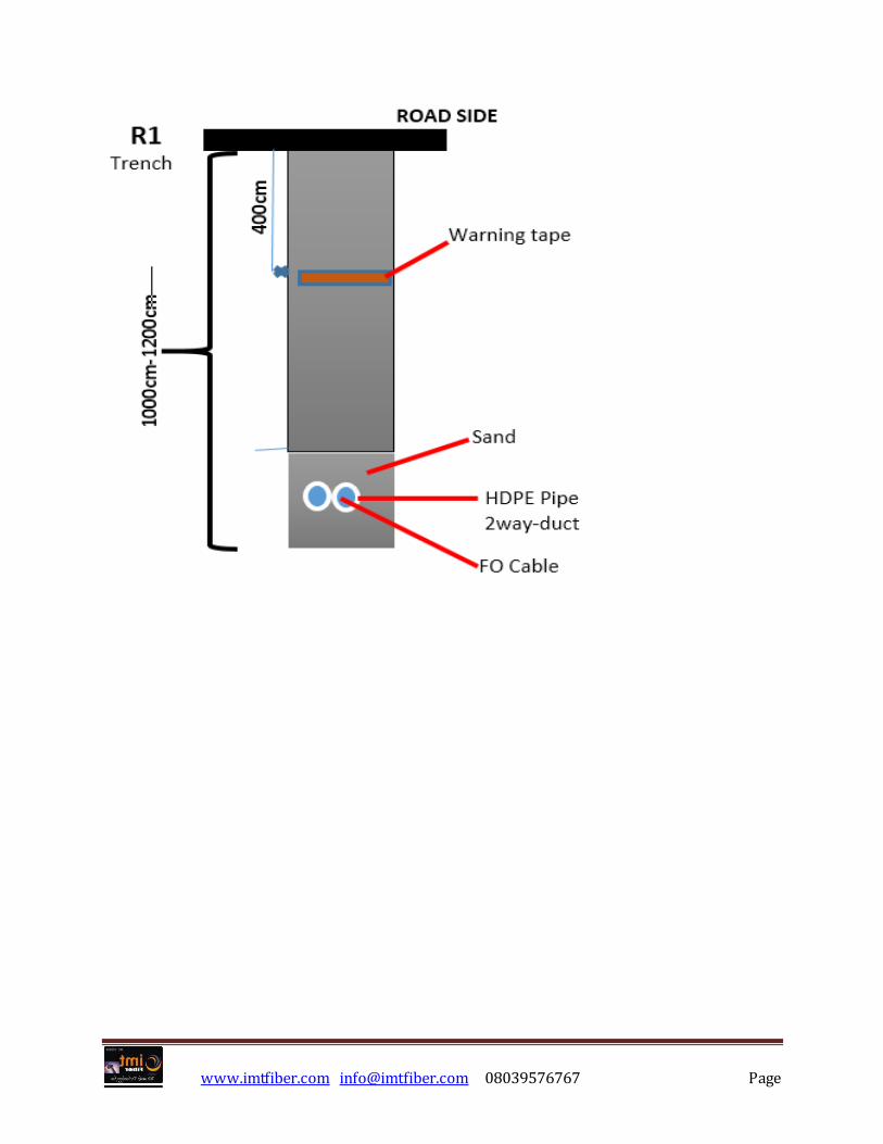
Trench Type S1 or R1 – Filling the trench with the extracted
material from the soil. This trench type can be regarded as deep
trench of 1.2m deep ,as approved by the client. This type of trench is
achievable mostly in the backborne
www.imtfiber.com [email protected] 08039576767 Page
www.imtfiber.com [email protected] 08039576767 Page
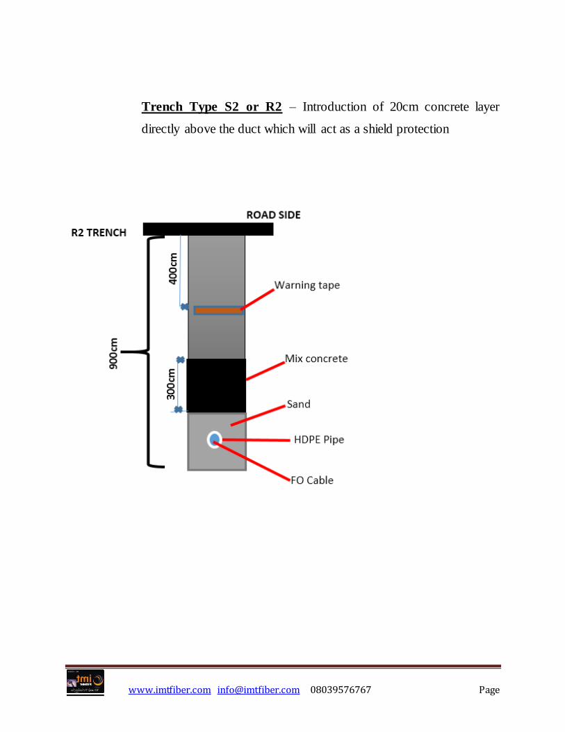
Trench Type S2 or R2 – Introduction of 20cm concrete layer
directly above the duct which will act as a shield protection
www.imtfiber.com [email protected] 08039576767 Page
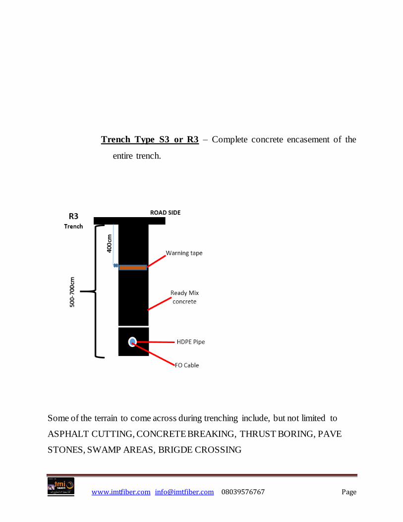
Trench Type S3 or R3 – Complete concrete encasement of the
entire trench.
Some of the terrain to come across during trenching include, but not limited to
ASPHALT CUTTING, CONCRETE BREAKING, THRUST BORING, PAVE
STONES, SWAMP AREAS, BRIGDE CROSSING

www.imtfiber.com [email protected] 08039576767 Page
Where there is road crossing, the road must be backfilled and reinstated with
asphalt or any materials used for the constructed of the road before cutting. This
shall be done immediately after the installation of the ducts.
Not more than 100metres trench shall be left open overnight. Warning signs,
fencing, guards and watchmen are required where necessary.
The trench shall be dug in such a way that the minimum cover over the uppermost
layer of ducts is 100cm in carriageway and 45cm in footpaths. The bottom of the
trench shall be level and free from stones and debris, or other objects which may
damage the ducts.
MANHOLE WORK
Manhole, Handhole, JB or any other name it is called, is simply a concrete box
found on fiber project route mainly for accessibility, maintenance and securing the
enclosure.
As to allow easily splice box installation and cable coils with respect of maximum
bending radii, the dimensions of the manhole will not be less than:
www.imtfiber.com [email protected] 08039576767 Page
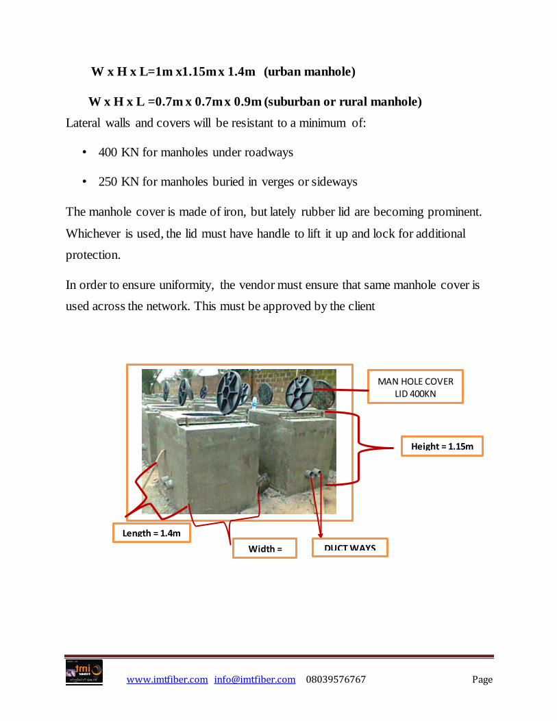
W x H x L=1m x1.15m x 1.4m (urban manhole)
W x H x L =0.7m x 0.7m x 0.9m (suburban or rural manhole)
Lateral walls and covers will be resistant to a minimum of:
• 400 KN for manholes under roadways
• 250 KN for manholes buried in verges or sideways
The manhole cover is made of iron, but lately rubber lid are becoming prominent.
Whichever is used, the lid must have handle to lift it up and lock for additional
protection.
In order to ensure uniformity, the vendor must ensure that same manhole cover is
used across the network. This must be approved by the client
MAN HOLE COVER LID 400KN
Width =
1m
Height = 1.15m
Length = 1.4m
DUCT WAYS
www.imtfiber.com [email protected] 08039576767 Page
TYPES OF MANHOLE
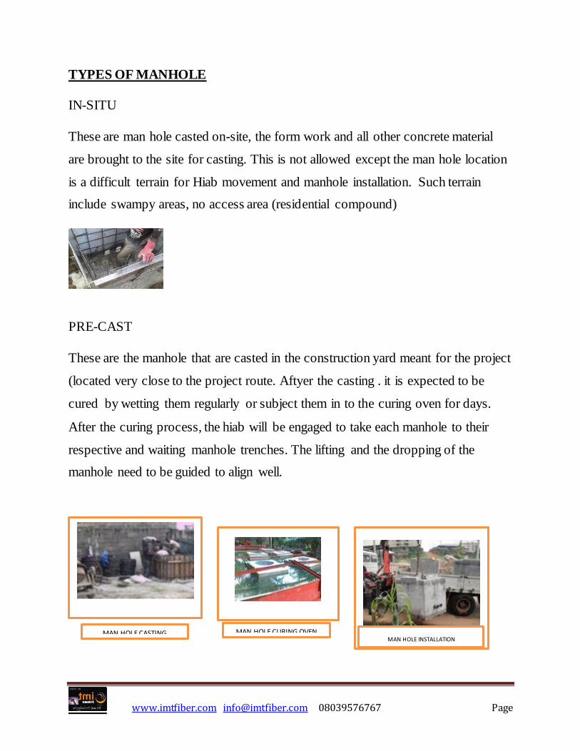
IN-SITU
These are man hole casted on-site, the form work and all other concrete material
are brought to the site for casting. This is not allowed except the man hole location
is a difficult terrain for Hiab movement and manhole installation. Such terrain
include swampy areas, no access area (residential compound)
PRE-CAST
These are the manhole that are casted in the construction yard meant for the project
(located very close to the project route. Aftyer the casting . it is expected to be
cured by wetting them regularly or subject them in to the curing oven for days.
After the curing process, the hiab will be engaged to take each manhole to their
respective and waiting manhole trenches. The lifting and the dropping of the
manhole need to be guided to align well.
MAN HOLE CASTING
MAN HOLE CURING OVEN
MAN HOLE INSTALLATION
www.imtfiber.com [email protected] 08039576767 Page
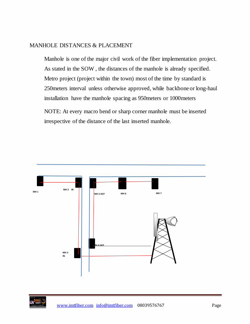
MANHOLE DISTANCES & PLACEMENT
Manhole is one of the major civil work of the fiber implementation project.
As stated in the SOW , the distances of the manhole is already specified.
Metro project (project within the town) most of the time by standard is
250meters interval unless otherwise approved, while backbone or long-haul
installation have the manhole spacing as 950meters or 1000meters
NOTE: At every macro bend or sharp corner manhole must be inserted
irrespective of the distance of the last inserted manhole.
MH 1 MH 2 IN
MH 3
IN
MH 5 OUT
MH 4 OUT
MH 6 MH 7
www.imtfiber.com [email protected] 08039576767 Page
Where bridges, streams or other obstacles require crossing, chambers should
be placed on either side of the obstruction.
Manholes should not be installed on steep banks or slopes.
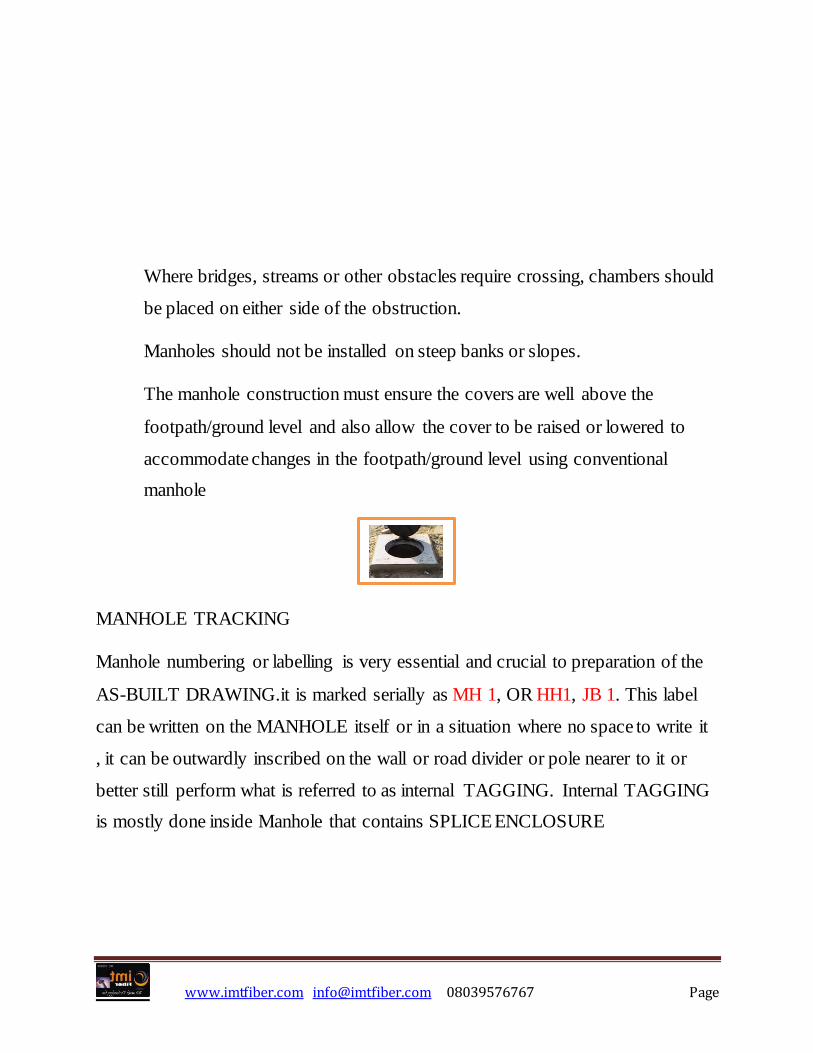
The manhole construction must ensure the covers are well above the
footpath/ground level and also allow the cover to be raised or lowered to
accommodate changes in the footpath/ground level using conventional
manhole
MANHOLE TRACKING
Manhole numbering or labelling is very essential and crucial to preparation of the
AS-BUILT DRAWING.it is marked serially as MH 1, OR HH1, JB 1. This label
can be written on the MANHOLE itself or in a situation where no space to write it
, it can be outwardly inscribed on the wall or road divider or pole nearer to it or
better still perform what is referred to as internal TAGGING. Internal TAGGING
is mostly done inside Manhole that contains SPLICE ENCLOSURE

www.imtfiber.com [email protected] 08039576767 Page
What is route marker? This is one of the project deliverables that indicates that a
telecom cable or underground telecom facility already passed through the route.
This is very essential for maintenance and more so for the new telecom company
to be guided while trying to trench same route.
NOTE: As rule of Thumb every underground facility sighted (be it water pipe,
telecom cable, electric cable etc.) must be given minimum of 1meter either side
before any other facility be installed.
The route marker must be placed at regular interval as stated by the client.
NOTE: in metro project of 250m Manhole intervals the route marker is also placed
in between manhole (hence route marker interval on a metro project is 250ms.
In a backbone or long-haul project where the manhole interval is 950m 0r 1000m
as the case may be, the route marker is also placed at such intervals, except at a
micro bend or sharp turning
ROUTE MARKER

www.imtfiber.com [email protected] 08039576767 Page
Samples of route markers of Nigeria telecom companies
DUCTING & COUPLING
Galvanized Steel pipe of internal diameter of 100mm and normal length of 6m
shall be installed in areas requiring additional protection for optical fiber cable and
where the use of PVC duct is susceptible to damage. Also it shall be installed
where instances of road crossing. Steel pipe shall be used when crossing the
bridge, open sewer ditches, under railway and when crossing major roads.
Duct ends shall be closed during construction with rubber plugs to prevent dust and
water from entering
Suitable plug shall be provided and inserted into the end of each duct to prevent the
ingress of water and/or foreign matter
www.imtfiber.com [email protected] 08039576767 Page
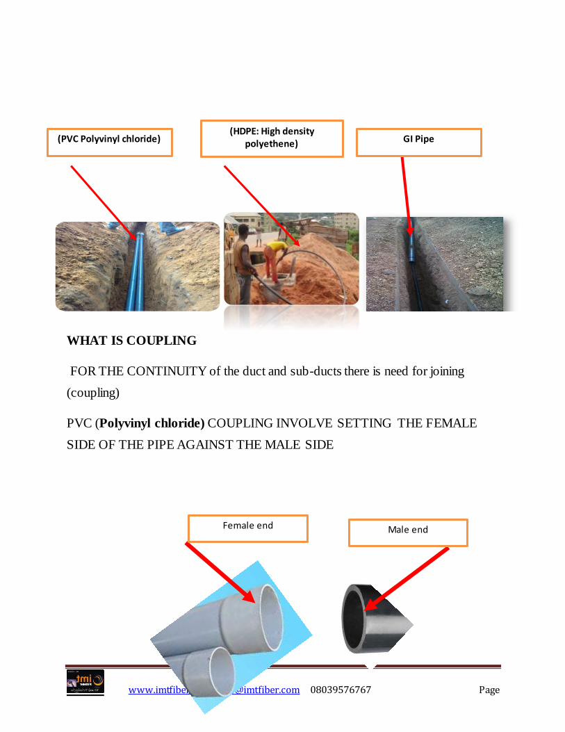
WHAT IS COUPLING
FOR THE CONTINUITY of the duct and sub-ducts there is need for joining
(coupling)
PVC (Polyvinyl chloride) COUPLING INVOLVE SETTING THE FEMALE
SIDE OF THE PIPE AGAINST THE MALE SIDE
(PVC Polyvinyl chloride) (HDPE: High density
polyethene) GI Pipe
Female end Male end
www.imtfiber.com [email protected] 08039576767 Page
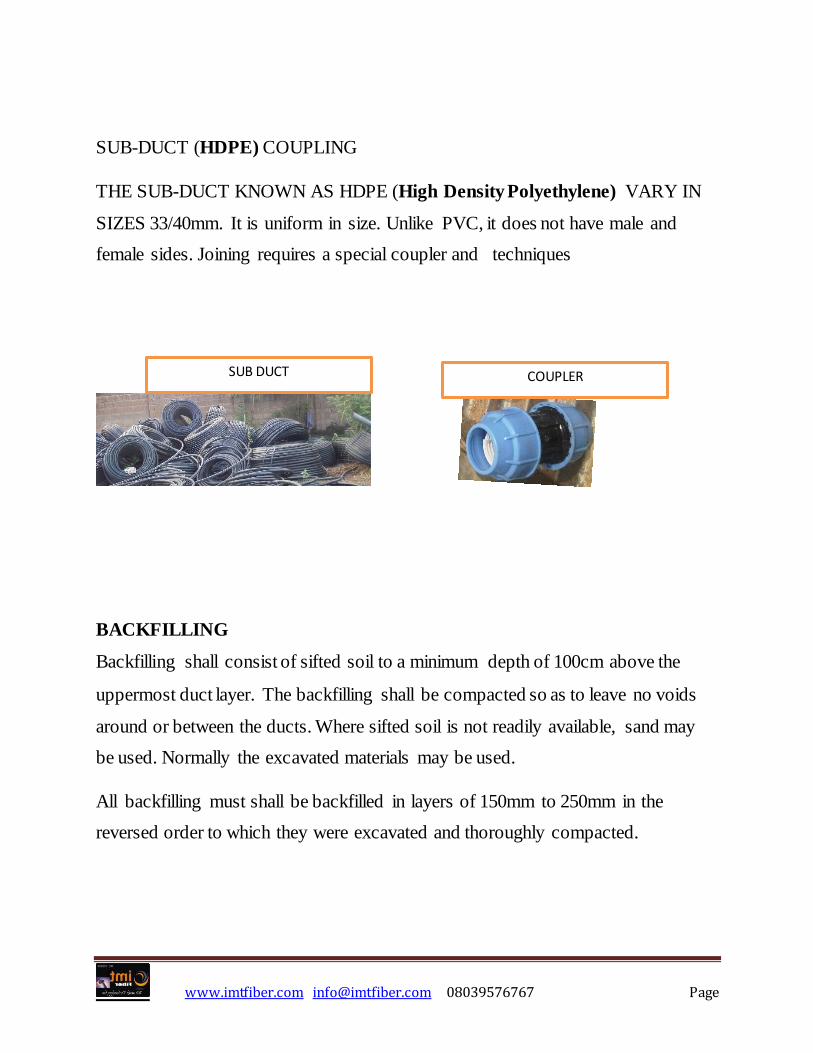
SUB-DUCT (HDPE) COUPLING
THE SUB-DUCT KNOWN AS HDPE (High Density Polyethylene) VARY IN
SIZES 33/40mm. It is uniform in size. Unlike PVC, it does not have male and
female sides. Joining requires a special coupler and techniques
BACKFILLING
Backfilling shall consist of sifted soil to a minimum depth of 100cm above the
uppermost duct layer. The backfilling shall be compacted so as to leave no voids
around or between the ducts. Where sifted soil is not readily available, sand may
be used. Normally the excavated materials may be used.
All backfilling must shall be backfilled in layers of 150mm to 250mm in the
reversed order to which they were excavated and thoroughly compacted.
SUB DUCT COUPLER

www.imtfiber.com [email protected] 08039576767 Page
Warning tape is required here before total backfilling. Reinstatement only takes
place where major terrain such as asphalt cutting and concrete breaking take place
FIBER WORK
The optical network is to be constructed using quality optical cable that is suitable
for the underground environment. The cable is provided by the Client most of the
time.
The performance of the cable to use is prescribed by the client (the cable types,
cable wavelength and cable attenuation, all these are specified in the SOW
Cable installation must comply with international standards
Bend radius during installation should not be less than 20x outside diameter of
cable while the minimum bend radius after installation should not less than 10x
www.imtfiber.com [email protected] 08039576767 Page
outside diameter of cable. Cable slack shall be provided as 5meter within the
Manhole and 10meters at termination points. A minimum of 0.5m is required as
slack within the termination enclosure.
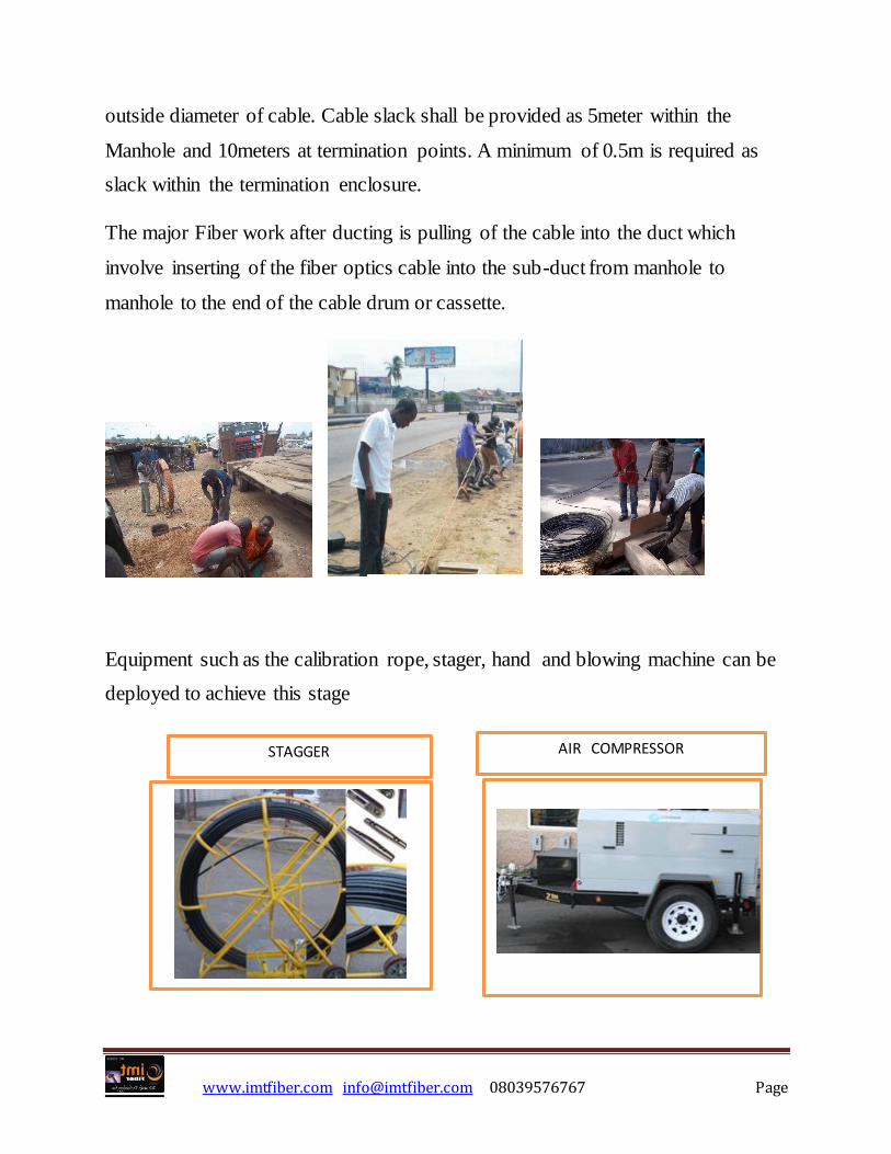
The major Fiber work after ducting is pulling of the cable into the duct which
involve inserting of the fiber optics cable into the sub-duct from manhole to
manhole to the end of the cable drum or cassette.
Equipment such as the calibration rope, stager, hand and blowing machine can be
deployed to achieve this stage
STAGGER AIR COMPRESSOR
www.imtfiber.com [email protected] 08039576767 Page
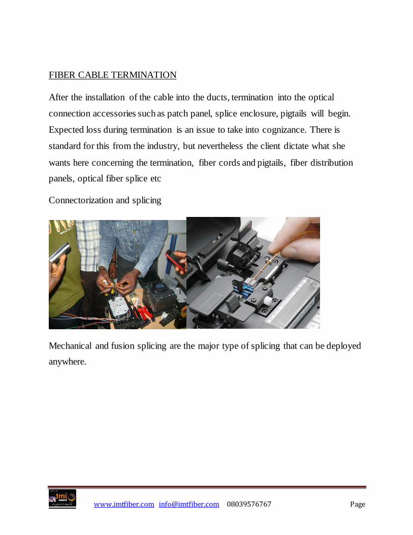
FIBER CABLE TERMINATION
After the installation of the cable into the ducts, termination into the optical
connection accessories such as patch panel, splice enclosure, pigtails will begin.
Expected loss during termination is an issue to take into cognizance. There is
standard for this from the industry, but nevertheless the client dictate what she
wants here concerning the termination, fiber cords and pigtails, fiber distribution
panels, optical fiber splice etc
Connectorization and splicing
Mechanical and fusion splicing are the major type of splicing that can be deployed
anywhere.
www.imtfiber.com [email protected] 08039576767 Page
Fiber optic cable splicing procedure (How to splice fiber optic cable)
1. Strip fiber cable jacket. Strip back about 3 meters of fiber cable jacket to
expose the fiber loose tubes or tight buffered fibers. Use cable rip cord to cut
through the fiber jacket. Then carefully peel back the jacket and expose the
insides. Cut off the excess jacket. Clean off all cable gel with cable gel
remover. Separate the fiber loose tubes and buffers by carefully cutting away
any yarn or sheath. Leave enough of the strength member to properly secure
the cable in the splice enclose.
2. Strip fiber tubes. For a loose tube fiber cable, strip away about 2 meters of
fiber tube using a buffer tube stripper and expose the individual fibers.
3. Clean cable gel. Carefully clean all fibers in the loose tube of any filling gel
with cable gel remover.
4. Secure cable tubes. Secure the end of the loose tube to the splice tray and lay
out cleaned and separated fibers on the table. Strip and clean the other cable
tube’s fiber that is to be spliced, and secure to the splice tray.
5. Strip first splicing fiber. Hold the first splicing fiber and remove the 250um
fiber coating to expose 5cm of 125um bare fiber cladding with fiber coating
stripper tool. For tight buffered fibers, remove 5cm of 900um tight buffer first
with a buffer stripping tool, and then remove the 5cm of 250um coating.
6. Place the fusion splice protection sleeve. Put a fusion splice protection sleeve
onto the fiber being spliced.
7. Clean the bare fiber. Carefully clean the stripped bare fiber with lint-free
wipes soaked in isopropyl alcohol. After cleaning, prevent the fiber from
touching anything.
www.imtfiber.com [email protected] 08039576767 Page
8. Fiber cleaving. With a high precision fiber cleaver, cleave the fiber to a
specified length according to your fusion splicer’s manual.
9. Prepare second fiber being spliced. Strip, clean and cleave the other fiber to
be spliced.
10. Fusion splicing. Place both fibers in the fusion splicer and do the fusion splice
according to its manual.
11. Heat shrink the fusion splice protection sleeve. Slide the fusion splice
protection sleeve on the joint and put it into the heat shrink oven, and press the
heat button.
12. Place splice into splice tray. Carefully place the finished splice into the splice
tray and loop excess fiber around its guides. Ensure that the fiber’s minimum
bending radius is not compromised.
13. Perform OTDR test. Perform a OTDR test of the splice and redo the splice if
necessary.
14. Close the splice tray. After all fibers have been spliced, carefully close the
splice tray and place it into the splice enclosure.
15. Bidirectional OTDR test (or power meter test). Test the splices with an
OTDR or power meter from both directions.
16. Mount the splice enclosure. Close and mount the splice enclosure if all
splices meet the specifications.
TESTING
Fusion splicers are used to create long cable lengths by splicing multiple cable
segments. Although the splicer will give an estimate of the splice loss, the only

www.imtfiber.com [email protected] 08039576767 Page
way to test it is with an OTDR. Since OTDRs have directional errors, testing may
be required from both directions and averaged. Generally long concatenated cables
are tested with an OTDR and traces kept for documentation in case of restoration.
OPTICAL POWER- POWER OR LOSS? (“ABSOLUTE” VS.
“RELATIVE”)
Practically every measurement in fiber optics refers to optical power. The
power output of a transmitter or the input to recever is “absolute” optical
power measurements, that is, you measure the actual value of the power.
Absolute optical power levels are measured in dBm. 0 dBm is equivalent to 1 mW
of power, hence the “m” in dBm