Embed Size (px)
Citation preview
h t t p : / / w w w . s e m i c o n . t o s h i b a . c o . j p / e n gS E M I C O N D U C T O R
PRODUCT GUIDE
Fiber-Optic Devices TOSLINKTM
2011-2
VCC
VCC
Input Output
Input Output
VCC
VCC
Optical cable
Optical transmitting module Optical receiving module
Electrical inputsignal
Linedriver
Twisted-pair cable
Electricalconnector
Electricalconnector
Electrical outputsignal
Linereceiver
Electrical inputsignal
Transmittingmodule
Transmittingcircuit
Optical cable
E/O converter
ReceivingcircuitPhotodiode
O/E converter
Fiber-optic link
opticalconnector
Electrical outputsignal
Receivingmodule
opticalconnector
LED
(a) Photocoupler
(b) TOSLINK
(a) Data transmission using a twisted-pair cable
(b) Data transmission using an optical cable
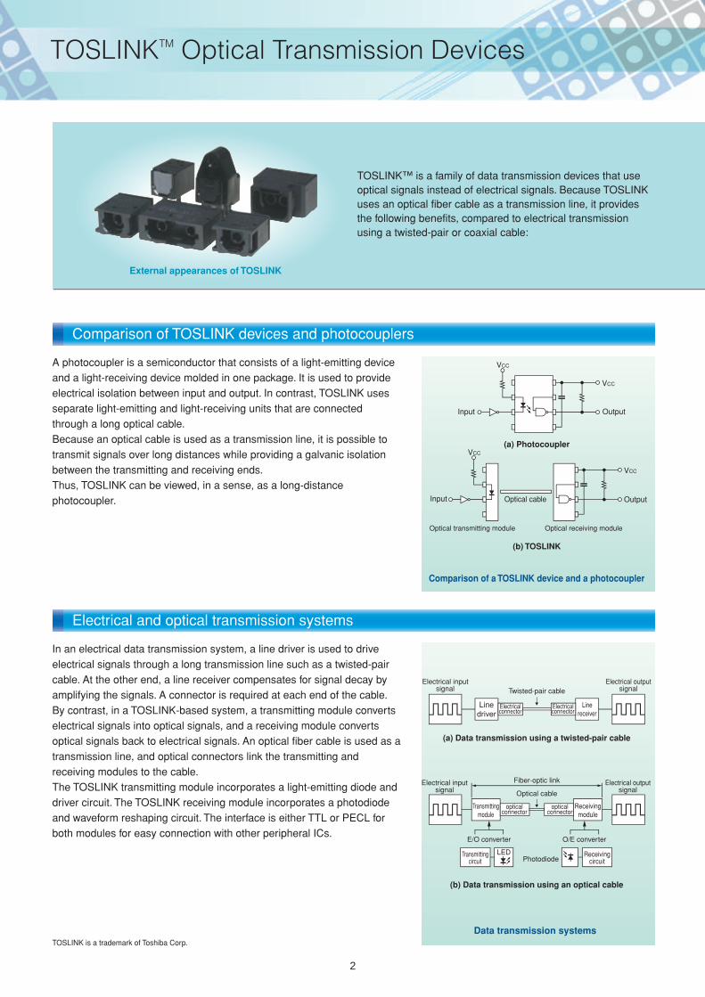
Data transmission systems
Comparison of a TOSLINK device and a photocoupler
TOSLINK™ is a family of data transmission devices that use optical signals instead of electrical signals. Because TOSLINK uses an optical fiber cable as a transmission line, it provides the following benefits, compared to electrical transmission using a twisted-pair or coaxial cable:
External appearances of TOSLINK
A photocoupler is a semiconductor that consists of a light-emitting device and a light-receiving device molded in one package. It is used to provide electrical isolation between input and output. In contrast, TOSLINK uses separate light-emitting and light-receiving units that are connected through a long optical cable.Because an optical cable is used as a transmission line, it is possible to transmit signals over long distances while providing a galvanic isolation between the transmitting and receiving ends.Thus, TOSLINK can be viewed, in a sense, as a long-distance photocoupler.
In an electrical data transmission system, a line driver is used to drive electrical signals through a long transmission line such as a twisted-pair cable. At the other end, a line receiver compensates for signal decay by amplifying the signals. A connector is required at each end of the cable.By contrast, in a TOSLINK-based system, a transmitting module converts electrical signals into optical signals, and a receiving module converts optical signals back to electrical signals. An optical fiber cable is used as a transmission line, and optical connectors link the transmitting and receiving modules to the cable.The TOSLINK transmitting module incorporates a light-emitting diode and driver circuit. The TOSLINK receiving module incorporates a photodiode and waveform reshaping circuit. The interface is either TTL or PECL for both modules for easy connection with other peripheral ICs.
TOSLINK is a trademark of Toshiba Corp.
Electrical and optical transmission systems
Comparison of TOSLINK devices and photocouplers
2
TOSLINKTM Optical Transmission Devices
Optical ray
Sheathing
Cladding(low refractive index for confinement of light)
Core(high refractive index for transmission of light)
LED
VCC
GND1
Output
GND24
3
2
1
Amp circuit
ATC circuit
Receiving IC
Comparator
Input 4
IF-CONT 2
VCC 3
GND 1
Reference voltagegenerating circuit
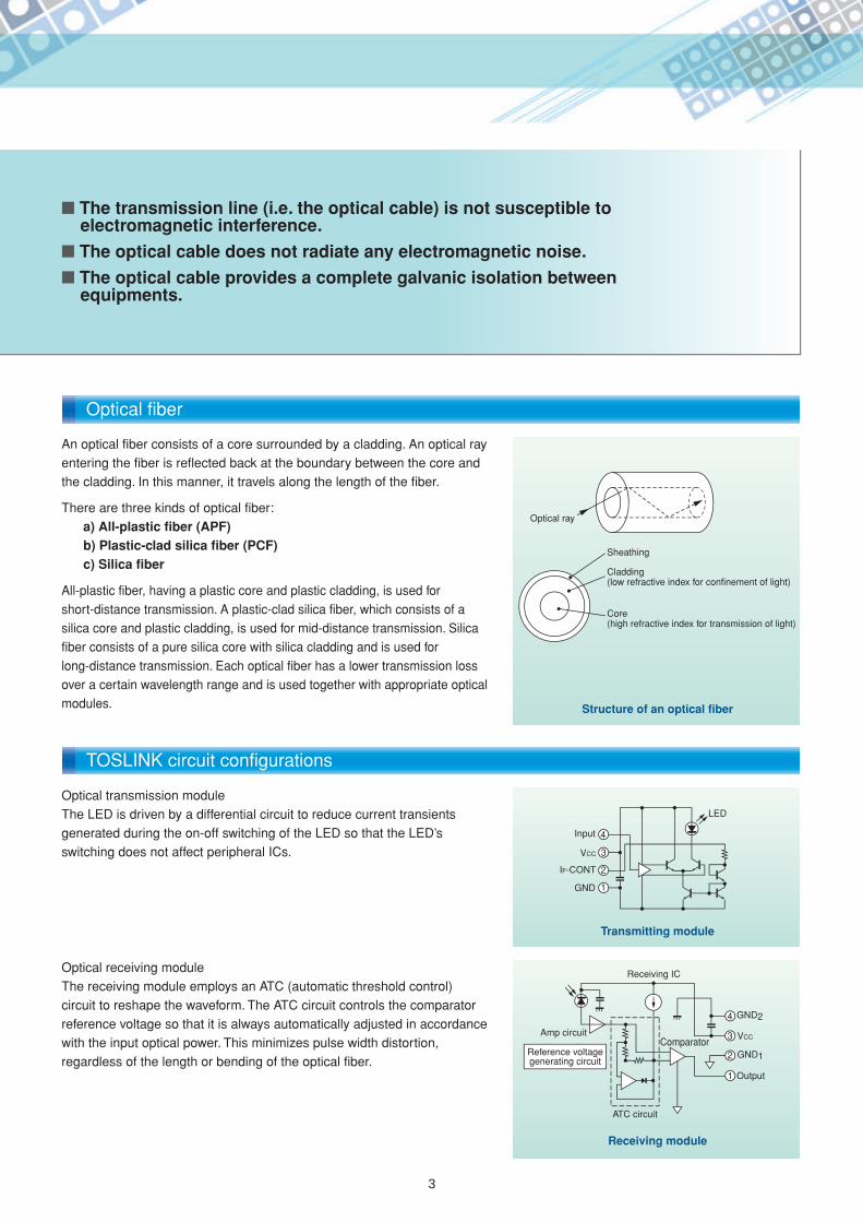
The transmission line (i.e. the optical cable) is not susceptible to electromagnetic interference.
The optical cable does not radiate any electromagnetic noise.
The optical cable provides a complete galvanic isolation between equipments.
An optical fiber consists of a core surrounded by a cladding. An optical ray entering the fiber is reflected back at the boundary between the core and the cladding. In this manner, it travels along the length of the fiber.
There are three kinds of optical fiber:a) All-plastic fiber (APF)b) Plastic-clad silica fiber (PCF)c) Silica fiber
All-plastic fiber, having a plastic core and plastic cladding, is used for short-distance transmission. A plastic-clad silica fiber, which consists of a silica core and plastic cladding, is used for mid-distance transmission. Silica fiber consists of a pure silica core with silica cladding and is used for long-distance transmission. Each optical fiber has a lower transmission loss over a certain wavelength range and is used together with appropriate optical modules.
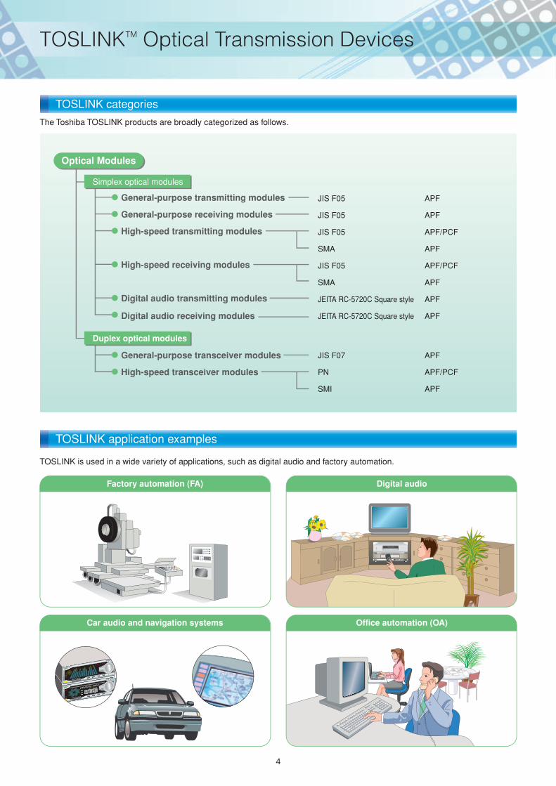
Optical transmission moduleThe LED is driven by a differential circuit to reduce current transients generated during the on-off switching of the LED so that the LED’s switching does not affect peripheral ICs.
Optical receiving moduleThe receiving module employs an ATC (automatic threshold control) circuit to reshape the waveform. The ATC circuit controls the comparator reference voltage so that it is always automatically adjusted in accordance with the input optical power. This minimizes pulse width distortion, regardless of the length or bending of the optical fiber.
Structure of an optical fiber
Transmitting module
Receiving module
TOSLINK circuit configurations
Optical fiber
3
Duplex optical modules
Simplex optical modules
JIS F05 APF
JIS F05 APF
JIS F05 APF/PCF
SMA APF
JIS F05 APF/PCF
SMA APF
JEITA RC-5720C Square style APF
JEITA RC-5720C Square style APF
JIS F07 APF
PN APF/PCF
SMI APF
General-purpose transmitting modules
General-purpose transceiver modules
General-purpose receiving modules
High-speed transmitting modules
High-speed receiving modules
Digital audio transmitting modules
High-speed transceiver modules
Digital audio receiving modules
BX-GT BEAR
L
R
200-10008548
Optical Modules
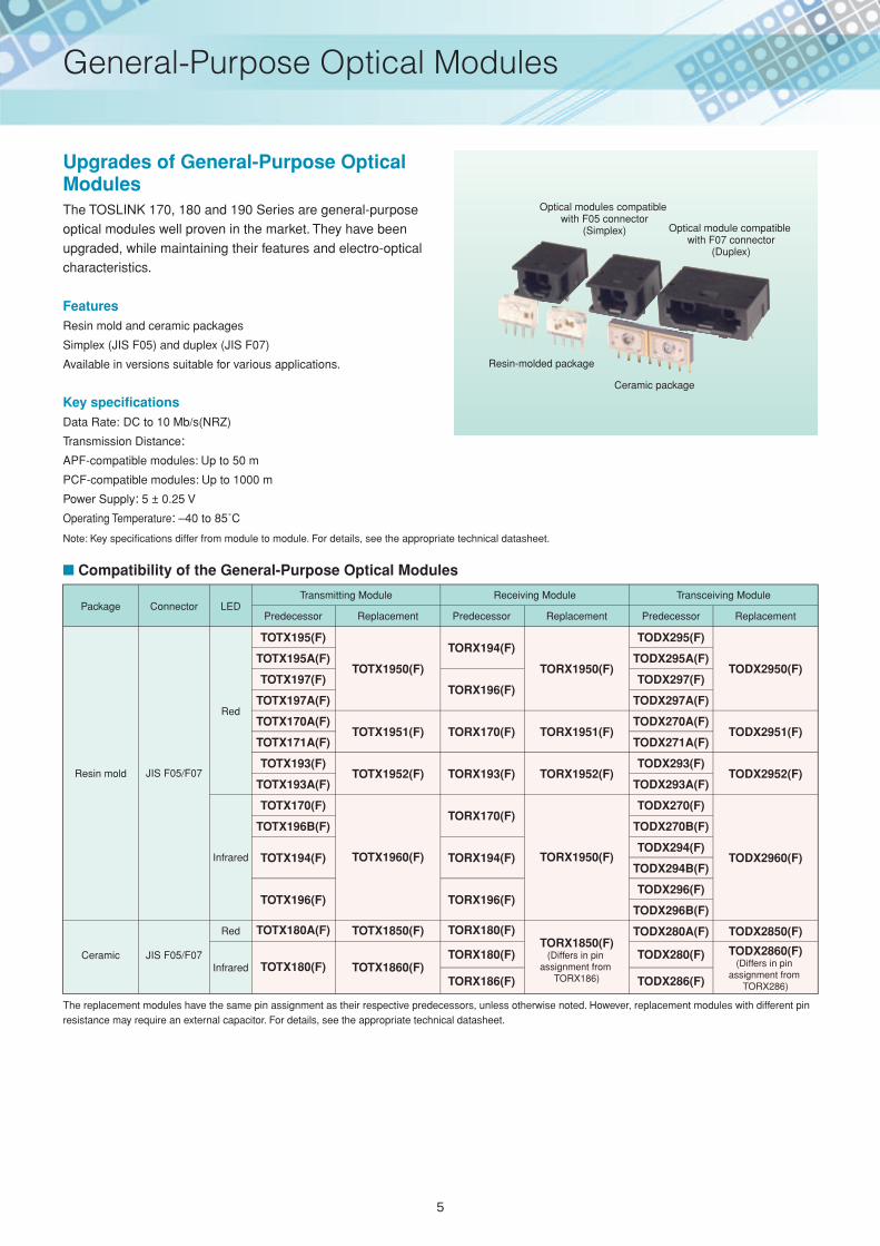
TOSLINK is used in a wide variety of applications, such as digital audio and factory automation.
The Toshiba TOSLINK products are broadly categorized as follows.
Car audio and navigation systems
Digital audio
Office automation (OA)
Factory automation (FA)
TOSLINK categories
TOSLINK application examples
4
TOSLINKTM Optical Transmission Devices
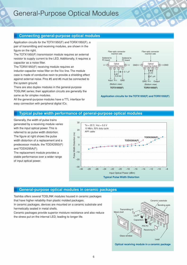
Upgrades of General-Purpose Optical ModulesThe TOSLINK 170, 180 and 190 Series are general-purpose optical modules well proven in the market. They have been upgraded, while maintaining their features and electro-optical characteristics.
FeaturesResin mold and ceramic packages
Simplex (JIS F05) and duplex (JIS F07)
Available in versions suitable for various applications.
Key specificationsData Rate: DC to 10 Mb/s(NRZ)
Transmission Distance: APF-compatible modules: Up to 50 m
PCF-compatible modules: Up to 1000 m
Power Supply: 5 ± 0.25 V
Operating Temperature: –40 to 85˚C
Package
Resin mold
Ceramic JIS F05/F07
JIS F05/F07
Connector LEDPredecessor
TOTX194(F)
TOTX196(F)
TOTX180A(F)
TOTX195(F)
TOTX195A(F)
TOTX197(F)
TOTX197A(F)
TOTX170A(F)
TOTX171A(F)
TOTX193(F)
TOTX193A(F)
TOTX170(F)
TOTX196B(F)
Replacement
TOTX1950(F)
TOTX1951(F)
TOTX1952(F)
TOTX1960(F)
TOTX1850(F)
TOTX1860(F)
Transmitting Module Receiving Module
Resin-molded package
Ceramic package
Optical modules compatible with F05 connector
(Simplex) Optical module compatible with F07 connector
(Duplex)
Transceiving Module
Predecessor
TORX194(F)
TORX196(F)
TORX170(F)
TORX193(F)
TORX170(F)
TORX194(F)
TORX196(F)
TORX180(F)
TORX180(F)
TORX186(F)
TODX280(F)
TODX286(F)
Replacement
TORX1950(F)
TORX1951(F)
TORX1952(F)
TORX1950(F)
TORX1850(F)(Differs in pin
assignment from TORX186)
Predecessor
TODX295(F)
TODX295A(F)
TODX297(F)
TODX297A(F)
TODX270A(F)
TODX271A(F)
TODX293(F)
TODX293A(F)
TODX270(F)
TODX270B(F)
TODX294(F)
TODX294B(F)
TODX296(F)
TODX296B(F)
TODX280A(F)
Replacement
TODX2950(F)
TODX2951(F)
TODX2952(F)
TODX2960(F)
TODX2850(F)
TODX2860(F)(Differs in pin
assignment from TORX286)
Red
Infrared
Red
Infrared TOTX180(F)
The replacement modules have the same pin assignment as their respective predecessors, unless otherwise noted. However, replacement modules with different pin resistance may require an external capacitor. For details, see the appropriate technical datasheet.
Compatibility of the General-Purpose Optical Modules
Note: Key specifications differ from module to module. For details, see the appropriate technical datasheet.
5
General-Purpose Optical Modules
Metal shell
Glass window
Transmitting IC
LED
PIN-PD
Receiving IC
Lead
Ceramic substrate
Bonding pads
Capacitors
4
5 6
3 2 1
TOTX1950(F)
VCC GND
5.6 k
Input
Soldered toPC board
Fiber-optic connectorinsertion side
Opticaltransmitting module
Soldered toPC board
(Bottom view)
0.1 F
4
5 6
3 2 1
TORX1950(F)
Opticalreceiving module
VCCGND
GND GND
47 H
0.1 F
Output
(Bottom view)
Fiber-optic connectorinsertion side
Typical Pulse Width Distortion
Input Optical Power (dBm)
TODX295A(F)
Pul
se W
idth
Dis
tort
ion
(ns)
TODX2950(F)
Ta = 25˚C, Vcc = 5.0 V10 Mb/s, 50% duty cycleAPF cable
30
20
10
0
–10
–20
–30–30 –28 –26 –24 –22 –20 –18 –16 –14 –12 –10 –8
Toshiba offers several TOSLINK modules housed in ceramic packages that have higher reliability than plastic molded packages.In ceramic packages, devices are mounted on a ceramic substrate and hermetically sealed in metal shells.Ceramic packages provide superior moisture resistance and also reduce the stress put on the internal LED, leading to longer life.
Optical receiving module in a ceramic package
Application circuits for the TOTX1950(F) and TORX1950(F), a pair of transmitting and receiving modules, are shown in the figure on the right.The TOTX1950(F) transmission module requires an external resistor to supply current to the LED. Additionally, it requires a capacitor as a noise filter.The TORX1950(F) receiving module requires an inductor-capacitor noise filter on the Vcc line. The module case is made of conductive resin to provide a shielding effect against external noise. Pins #5 and #6 must be connected to the system ground.There are also duplex modules in the general-purpose TOSLINK series; their application circuits are generally the same as for simplex modules.All the general-purpose modules have a TTL interface for easy connection with peripheral digital ICs.
Application circuits for the TOTX1950(F) and TORX1950(F)
Generally, the width of pulse trains generated by a receiving module varies with the input optical power. This is referred to as pulse width distortion. The figure at right shows the pulse width distortion of a replacement and a predecessor module, the TODX2950(F) and TODX295A(F).The replacement module provides a stable performance over a wider range of input optical power.
Connecting general-purpose optical modules
Typical pulse width performance of general-purpose optical modules
General-purpose optical modules in ceramic packages
6
General-Purpose Optical Modules
The TODX2701(F) optical transceiver module supports APF (all-plastic fiber) and PCF (plastic-clad silica fiber) cables.The TODX2701(F) is compatible with PN and JIS F07 connectors and well suited for Fast Ethernet (125 Mb/s) transmission.
TODX2701(F) optical transceiver module
Data rate: 20 to 125 Mb/s (NRZ) Transmission distance: Up to 20 m of APF
Up to 100 m of GI-PCF Center wavelength: 650 nm Operating temperature: –10 to 70°C PECL interface Power supply: 3.3 ± 0.3 V
Key specifications
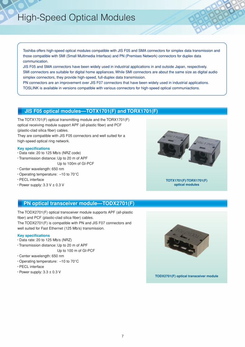
The TOTX1701(F) optical transmitting module and the TORX1701(F) optical receiving module support APF (all-plastic fiber) and PCF (plastic-clad silica fiber) cables.They are compatible with JIS F05 connectors and well suited for a high-speed optical ring network.
TOTX1701(F)/TORX1701(F)optical modules
Data rate: 20 to 125 Mb/s (NRZ code) Transmission distance: Up to 20 m of APF
Up to 100m of GI-PCF Center wavelength: 650 nm Operating temperature: –10 to 70°C PECL interface Power supply: 3.3 V ± 0.3 V
Key specifications
Toshiba offers high-speed optical modules compatible with JIS F05 and SMA connectors for simplex data transmission and those compatible with SMI (Small Multimedia Interface) and PN (Premises Network) connectors for duplex data communication.JIS F05 and SMA connectors have been widely used in industrial applications in and outside Japan, respectively.SMI connectors are suitable for digital home appliances. While SMI connectors are about the same size as digital audio simplex connectors, they provide high-speed, full-duplex data transmission.PN connectors are an improvement over JIS F07 connectors that have been widely used in industrial applications.TOSLINK is available in versions compatible with various connectors for high-speed optical communiactions.
JIS F05 optical modules—TOTX1701(F) and TORX1701(F)
PN optical transceiver module—TODX2701(F)
7
High-Speed Optical Modules
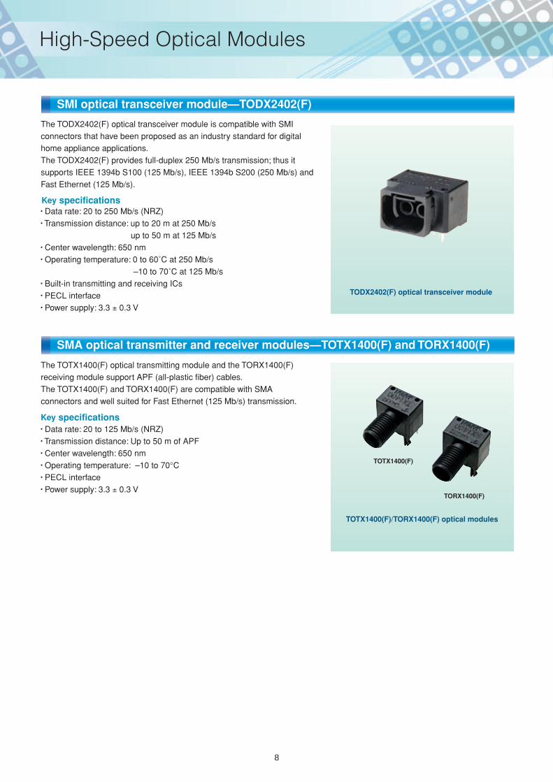
The TOTX1400(F) optical transmitting module and the TORX1400(F) receiving module support APF (all-plastic fiber) cables.The TOTX1400(F) and TORX1400(F) are compatible with SMA connectors and well suited for Fast Ethernet (125 Mb/s) transmission.
TOTX1400(F)/TORX1400(F) optical modules
Data rate: 20 to 125 Mb/s (NRZ) Transmission distance: Up to 50 m of APF Center wavelength: 650 nm Operating temperature: –10 to 70°C PECL interface Power supply: 3.3 0.3 V
Key specifications
TOTX1400(F)
TORX1400(F)
The TODX2402(F) optical transceiver module is compatible with SMI connectors that have been proposed as an industry standard for digital home appliance applications.The TODX2402(F) provides full-duplex 250 Mb/s transmission; thus it supports IEEE 1394b S100 (125 Mb/s), IEEE 1394b S200 (250 Mb/s) and Fast Ethernet (125 Mb/s).
TODX2402(F) optical transceiver module
Data rate: 20 to 250 Mb/s (NRZ) Transmission distance: up to 20 m at 250 Mb/s
up to 50 m at 125 Mb/s Center wavelength: 650 nm Operating temperature: 0 to 60˚C at 250 Mb/s
–10 to 70˚C at 125 Mb/s Built-in transmitting and receiving ICs PECL interface Power supply: 3.3 0.3 V
Key specifications
SMI optical transceiver module—TODX2402(F)
SMA optical transmitter and receiver modules—TOTX1400(F) and TORX1400(F)
8
High-Speed Optical Modules
VCC GND Output
3 2 1
TORX177(F,T)
C
L
Input VCC GND
3 2 1
Opticaltransmitting
module
Opticalreceivingmodule
Fiber optic insertion side Fiber optic insertion side
(Bottom view) (Bottom view)
TOTX177A(F,T)
0.1 F
C : 0.1 F (multilayer ceramic capacitor)L : 47 H
7 mm
TOTX177A(F,T)
TOTX177A(F,TJ)
TOTX147A(F,T)
TOTX147A(F,TJ)DC to 15
TORX177(F,T)
TORX177(F,TJ)
TORX147(F,T)
TORX147(F,TJ)0.1 to 15
TOTX177AL(F,T)
TOTX177AL(F,TJ)
TOTX147AL(F,T)
TOTX147AL(F,TJ)DC to 15
TORX177L(F,T)
TORX177L(F,TJ)
TORX147L(F,T)
TORX147L(F,TJ)0.1 to 15
TOTX177APL(F,T)
TOTX177APL(F,TJ)
TOTX147APL(F,T)
TOTX147APL(F,TJ)DC to 15
TORX177PL(F,T)
TORX177PL(F,TJ)
TORX147PL(F,T)
TORX147PL(F,TJ)0.1 to 15
Transmitter
Receiver
Transmitter
Receiver
Transmitter
Receiver
PackagePower Supply
5 V 3 V (3.3 V)Data Rate
(Mb/s)
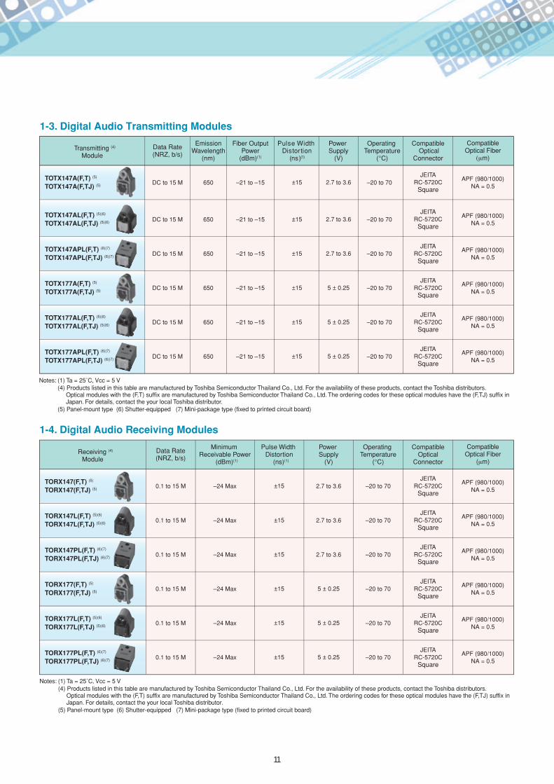
The digital audio optical modules are capable of transferring digital audio interface signals.The interface level and optical connector configuration conform to the Digital Audio Interface (DAI) standards JEITA CP-1212 and RC-5720C respectively. These modules are therefore ideal for a wide variety of applications, ranging from audio visual equipment such as DVD players to sound applications for personal computer and computer entertainment systems.
Digital audio optical modules are available with an optional shutter and in several choices of packages, supply voltages and data rates.
Note: (1) Products listed in this table are manufactured by Toshiba Semiconductor Thailand Co., Ltd. For the availability of these products, contact the Toshiba distributors. Optical modules with the (F,T) suffix are manufactured by Toshiba Semiconductor Thailand Co., Ltd. The ordering codes for these optical modules have the (F,TJ) suffix in Japan. For details, contact the your local Toshiba distributor.
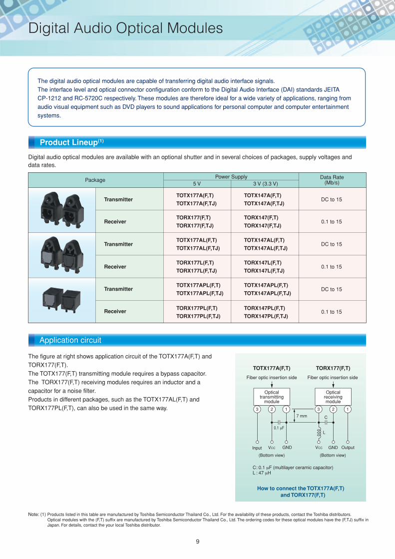
The figure at right shows application circuit of the TOTX177A(F,T) and TORX177(F,T). The TOTX177(F,T) transmitting module requires a bypass capacitor. The TORX177(F,T) receiving modules requires an inductor and a capacitor for a noise filter.Products in different packages, such as the TOTX177AL(F,T) and TORX177PL(F,T), can also be used in the same way.
How to connect the TOTX177A(F,T) and TORX177(F,T)
Product Lineup(1)
Application circuit
9
Digital Audio Optical Modules
TOTX1950(F) (2) TORX1950(F)
TOTX1951(F) TORX1950(F),TORX1951(F)
TOTX1952(F) TORX1952(F)
TOTX1960(F) TORX1950(F)
TOTX1850(F) (2)(3) TORX1850(F) (3)
TOTX1860(F) (3) TORX1850(F) (2)
TransmittingModule
Notes: (1) Ta = 25˚C, Vcc = 5 (2) An external resistor should be selected according to the transmission length, depending on the data rate.(3) Ceramic-packaged product
Notes:(1) Ta = 25˚C, Vcc = 5 V
ReceivingModule
Data Rate(NRZ, b/s)
TransmissionDistance
(m)(1)
Pulse Width Distortion
(ns)(1)
Power Supply
(V)
Operating Temperature
(°C)
Compatible Optical
Connector
Compatible Optical Fiber
m)
APF (980/1000)NA = 0.5
EmissionWavelength
(nm)
DC to 10 M Up to 50±30 (at 10 Mb/s)±55 (at 6 Mb/s)
5 ± 0.25 –40 to 85 JIS F05650
APF (980/1000)NA = 0.5
DC to 10 M Up to 10 ±30 (at 10 Mb/s) 5 ± 0.25 –40 to 85 JIS F05660
APF (980/1000)NA = 0.5
DC to 6 M Up to 40 ±55 (at 6 Mb/s) 5 ± 0.25 –40 to 85 JIS F05650
APF (980/1000)NA = 0.5
DC to 10 M Up to 50±30 (at 10 Mb/s)±55 (at 6 Mb/s)
5 ± 0.25 –40 to 85 JIS F05650
H-PCF (200/230)DC to 10 M Up to 1000±30 (at 10 Mb/s)±55 (at 6 Mb/s)
5 ± 0.25 –40 to 85 JIS F05770
H-PCF (200/230)DC to 10 M Up to 1000±30 (at 10 Mb/s)±55 (at 6 Mb/s)
5 ± 0.25 –40 to 85 JIS F05770
TOTX1400(F) TORX1400(F)
TOTX1701(F) TORX1701(F)
TransmittingModule
ReceivingModule
Data Rate(NRZ, b/s)
TransmissionDistance
(m)(1)
Power Supply
(V)
Operating Temperature
(°C)
Compatible Optical
Connector
Compatible Optical Fiber
m)
APF (980/1000)NA = 0.3
EmissionWavelength
(nm)
20 to 125 M Up to 50 3.3 ± 0.3 –10 to 70 SMA650
APF (980/1000)NA = 0.3
GI-PCF (200/230)20 to 125 M
Up to 20 (APF)Up to 100 (GI-PCF)
3.3 ± 0.3 –10 to 70 JIS F05650
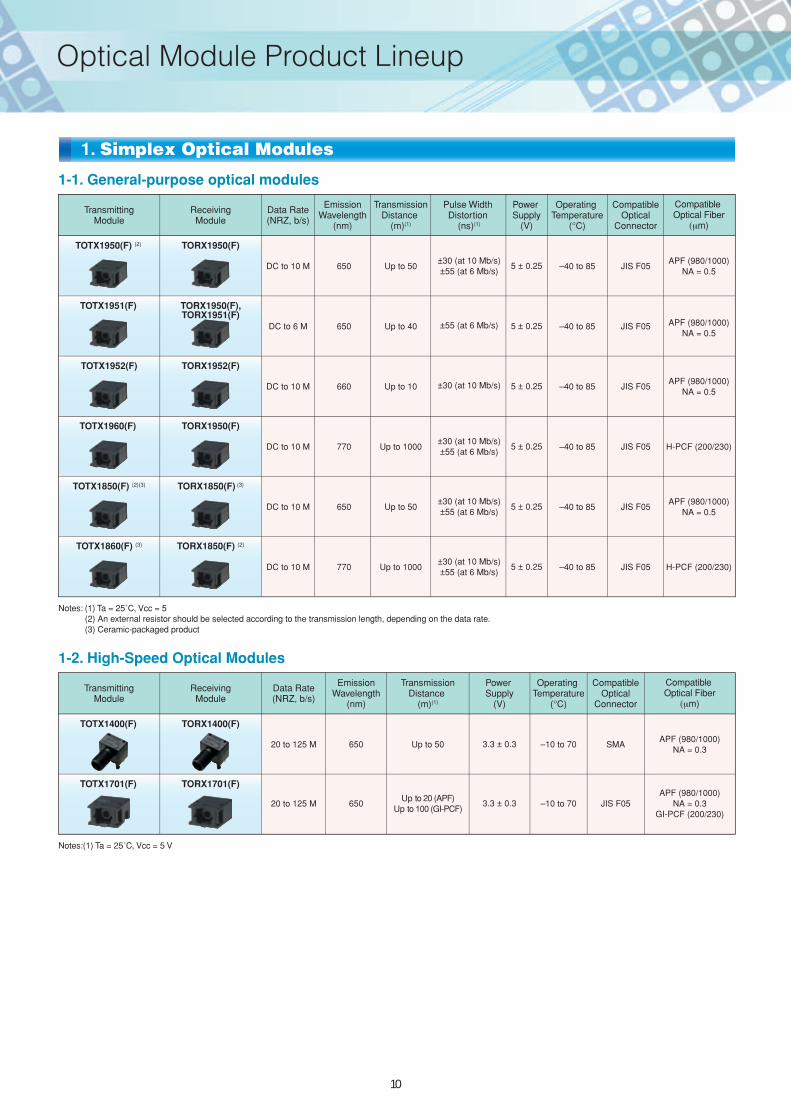
1-2. High-Speed Optical Modules
1-1. General-purpose optical modules
1. Simplex Optical Modules
10
Optical Module Product Lineup
TOTX147A(F,T) (5)
TOTX147A(F,TJ) (5)
TOTX147AL(F,T) (5)(6)
TOTX147AL(F,TJ) (5)(6)
TOTX147APL(F,T) (6)(7)
TOTX147APL(F,TJ) (6)(7)
TOTX177A(F,T) (5)
TOTX177A(F,TJ) (5)
TOTX177AL(F,T) (5)(6)
TOTX177AL(F,TJ) (5)(6)
TOTX177APL(F,T) (6)(7)
TOTX177APL(F,TJ) (6)(7)
Transmitting (4)
Module
Notes: (1) Ta = 25˚C, Vcc = 5 V(4) Products listed in this table are manufactured by Toshiba Semiconductor Thailand Co., Ltd. For the availability of these products, contact the Toshiba distributors.
Optical modules with the (F,T) suffix are manufactured by Toshiba Semiconductor Thailand Co., Ltd. The ordering codes for these optical modules have the (F,TJ) suffix in Japan. For details, contact the your local Toshiba distributor.
(5) Panel-mount type (6) Shutter-equipped (7) Mini-package type (fixed to printed circuit board)
Data Rate(NRZ, b/s)
Fiber OutputPower
(dBm)(1)
Pulse Width Distortion
(ns)(1)
Power Supply
(V)
Operating Temperature
(°C)
Compatible Optical
Connector
CompatibleOptical Fiber
m)
APF (980/1000)NA = 0.5
EmissionWavelength
(nm)
DC to 15 M –21 to –15 ±15 2.7 to 3.6 –20 to 70JEITA
RC-5720CSquare
650
APF (980/1000)NA = 0.5
DC to 15 M –21 to –15 ±15 2.7 to 3.6 –20 to 70JEITA
RC-5720CSquare
650
APF (980/1000)NA = 0.5
DC to 15 M –21 to –15 ±15 2.7 to 3.6 –20 to 70JEITA
RC-5720CSquare
650
APF (980/1000)NA = 0.5
DC to 15 M –21 to –15 ±15 5 ± 0.25 –20 to 70JEITA
RC-5720CSquare
650
APF (980/1000)NA = 0.5
DC to 15 M –21 to –15 ±15 5 ± 0.25 –20 to 70JEITA
RC-5720CSquare
650
APF (980/1000)NA = 0.5
DC to 15 M –21 to –15 ±15 5 ± 0.25 –20 to 70JEITA
RC-5720CSquare
650
TORX147(F,T) (5)
TORX147(F,TJ) (5)
TORX147L(F,T) (5)(6)
TORX147L(F,TJ) (5)(6)
Receiving (4)
ModuleData Rate(NRZ, b/s)
Pulse Width Distortion
(ns)(1)
Power Supply
(V)
Operating Temperature
(°C)
Compatible Optical
Connector
CompatibleOptical Fiber
( m)
APF (980/1000)NA = 0.5
Minimum Receivable Power
(dBm)(1)
0.1 to 15 M ±15 2.7 to 3.6 –20 to 70JEITA
RC-5720CSquare
–24 Max
APF (980/1000)NA = 0.5
0.1 to 15 M ±15 2.7 to 3.6 –20 to 70JEITA
RC-5720CSquare
–24 Max
TORX147PL(F,T) (6)(7)
TORX147PL(F,TJ) (6)(7)
TORX177(F,T) (5)
TORX177(F,TJ) (5)
APF (980/1000)NA = 0.5
0.1 to 15 M ±15 2.7 to 3.6 –20 to 70JEITA
RC-5720CSquare
–24 Max
APF (980/1000)NA = 0.5
0.1 to 15 M ±15 5 ± 0.25 –20 to 70JEITA
RC-5720CSquare
–24 Max
TORX177L(F,T) (5)(6)
TORX177L(F,TJ) (5)(6)
TORX177PL(F,T) (6)(7)
TORX177PL(F,TJ) (6)(7)
APF (980/1000)NA = 0.5
0.1 to 15 M ±15 5 ± 0.25 –20 to 70JEITA
RC-5720CSquare
–24 Max
APF (980/1000)NA = 0.5
0.1 to 15 M ±15 5 ± 0.25 –20 to 70JEITA
RC-5720CSquare
–24 Max
1-4. Digital Audio Receiving Modules
1-3. Digital Audio Transmitting Modules
11
TODX2950(F) (2)
TODX2951(F)
TODX2952(F)
TODX2960(F)
TODX2860(F) (3)
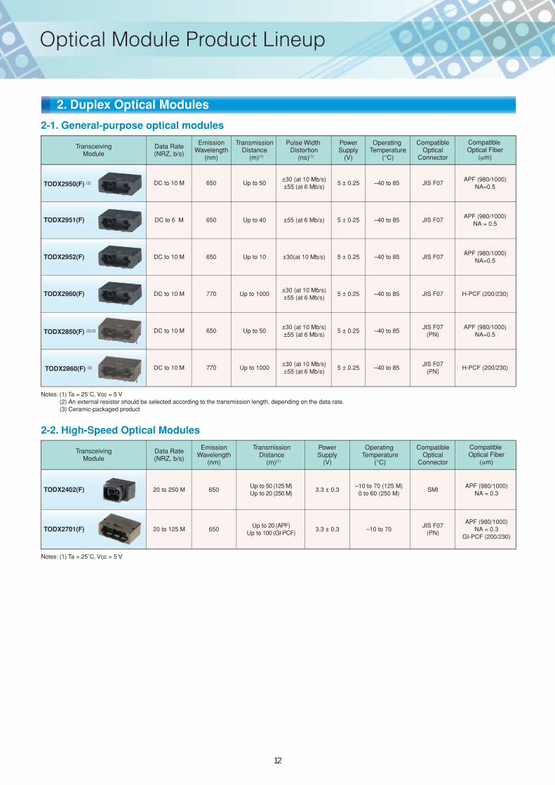
Notes: (1) Ta = 25˚C, Vcc = 5 V(2) An external resistor should be selected according to the transmission length, depending on the data rate.(3) Ceramic-packaged product
Notes: (1) Ta = 25˚C, Vcc = 5 V
TransceivingModule
Data Rate(NRZ, b/s)
TransmissionDistance
(m)(1)
Pulse Width Distortion
(ns)(1)
PowerSupply
(V)
Operating Temperature
(°C)
Compatible Optical
Connector
Compatible Optical Fiber
m)
APF (980/1000)NA=0.5
APF (980/1000)NA=0.5
H-PCF (200/230)
EmissionWavelength
(nm)
DC to 10 M Up to 50±30 (at 10 Mb/s)±55 (at 6 Mb/s)
5 ± 0.25 –40 to 85 JIS F07650
APF (980/1000)NA = 0.5
DC to 6 M Up to 40 ±55 (at 6 Mb/s) 5 ± 0.25 –40 to 85 JIS F07650
DC to 10 M Up to 10 ±30(at 10 Mb/s) 5 ± 0.25 –40 to 85 JIS F07650
TODX2850(F) (2)(3)APF (980/1000)
NA=0.5DC to 10 M Up to 50
±30 (at 10 Mb/s)±55 (at 6 Mb/s)
5 ± 0.25 –40 to 85650
H-PCF (200/230)DC to 10 M Up to 1000±30 (at 10 Mb/s)±55 (at 6 Mb/s)
5 ± 0.25 –40 to 85 JIS F07770
DC to 10 M Up to 1000±30 (at 10 Mb/s)±55 (at 6 Mb/s)
5 ± 0.25 –40 to 85770
TODX2402(F)
TransceivingModule
Data Rate(NRZ, b/s)
TransmissionDistance
(m)(1)
PowerSupply
(V)
Operating Temperature
(°C)
Compatible Optical
Connector
Compatible Optical Fiber
m)
EmissionWavelength
(nm)
APF (980/1000)NA = 0.3
20 to 250 MUp to 50 (125 M)Up to 20 (250 M)
3.3 ± 0.3–10 to 70 (125 M)
0 to 60 (250 M)SMI650
TODX2701(F) APF (980/1000)
NA = 0.3GI-PCF (200/230)
20 to 125 MUp to 20 (APF)
Up to 100 (GI-PCF)3.3 ± 0.3 –10 to 70650
2-2. High-Speed Optical Modules
2-1. General-purpose optical modules
2. Duplex Optical Modules
JIS F07(PN)
JIS F07(PN)
JIS F07(PN)
12
Optical Module Product Lineup
Category Product NumberCompatible
OpticalFiber
Optical Fibers with Optical Connectors
Asahi Kasei E-MaterialsMitsubishi
RayonToray
IndustriesHONDA TSUSHIN
KOGYO
Compatible Optical
Connector
TOTX1950(F)TOTX1951(F)TOTX1952(F)TOTX1850(F)TORX1950(F)TORX1951(F)TORX1952(F)TORX1850(F)
APF(980/1000 m)
NA = 0.5
LUCT1-TC1000- MLUCT1-TC1000-50K- MLUCT3-TC1000- MLUCT3-TC1000-50K- M
LUCT2-TC1000W- MLUCT2-TC1000W-60K- MLUCT4-TC1000W- MLUCT4-TC1000W-60K- M
TOCP100- MBTTOCP100P- MBTTOCP155- MBTTOCP155P- MBT
TOCP200- MBTTOCP200P- MBTTOCP255- MBTTOCP255P- MBT
JIS F05
APF (980/1000 m)
NA = 0.3
APF(980/1000 m)
NA = 0.5
APF(980/1000 m)
NA = 0.5
APF (980/1000 m)
NA = 0.3
RFA4011-
RFA3021M-
RFA4212G-
RFA4412M-LPG-Z0005P
Series
SMA
JEITARC-5720B
Square
JIS F07
PN
SMI
TOTX1701(F)TORX1701(F)
TOTX1400(F)TORX1400(F)
TOTX177A(F,T)TORX177(F,T) etc.
TODX2402(F)
TODX2950(F)TODX2951(F)TODX2952(F)TODX2850(F)
TODX2701(F)
General-purpose
Digital audio
High-speed
High-speed
General-purpose
1. APF
Simplex
Duplex
Category Product NumberCompatible
Optical Fiber
Optical Fibers with Optical Connectors
Sumitomo Electric Industries Oki Electric Cable
Compatible Optical Connector
CF-1071(HG-20/80) Series
CF-2071(HC-20/70) Series
CF-2071(HC-20/70) Series
CF-2071(HG-20/80) Series
GI-PCF(200/230 m)
H-PCF(200/230 m)
H-PCF(200/230 m)
OPC202HV Series
OPC202HV Series
PN
TOTX1701(F)TORX1701(F)
TODX2701(F)
TODX2960(F)TODX2860(F)
GI-PCF(200/230 m)
JIS F05
JIS F05
JIS F07
TOTX1960(F)TOTX1860(F)TORX1950(F)TORX1850(F)
General-purpose
High-speed
High-speed
General-purpose
2.PCF
Duplex
Simplex
13
Recommended Optical Fibers with Optical Connectors
1. Absolute Maximum Rating
The absolute maximum ratings are the limit values that must not be exceeded during device operation. Any one of them must not be exceeded.
Otherwise, the device characteristics may become unrestorable or the device may be permanently damaged in the worst case.
2. Operating Ranges
The operating range is the range of conditions necessary for the device to operate as specified in individual technical datasheets and databooks.
Even if a device is operated within the absolute maximum ratings, functional operation of the device or the specifications related to electrical
characteristics may not be guaranteed beyond the conditions indicated under “Operating Ranges.”
Exposure to conditions in excess of these ranges may also affect device reliability. Thus, special precautions are necessary in designing
electronic systems. For higher reliability, operating ranges should be derated for current, power and temperature.
3. LED Lifetime
Over a long period of time, the performance of an optical module will gradually be degraded, mostly be due to the lowering of the fiber output
power (Pf). This is caused by the degradation of the optical output of the LED used as the light source. Its cause may be a wafer crystallization
defect or mold resin stress, but no detail has been elucidated yet.
The lifetime of an LED is greatly influenced by the operating and environmental conditions in which it is used, as well as by the lifetime
characteristics specific to the device type. Thus, once the type of the LED and the operating conditions have been determined, it is
recommended to evaluate the lifetime characteristics.
Depending on the environmental conditions, Toshiba recommends that maintenance be performed regularly, including the checking of optical
output.
4. Soldering
Optical modules use semiconductor devices but are essentially optical components. When soldering, ensure that flux does not adhere to the light-emitting or light-receiving surfaces.Take the same care when cleaning off flux after soldering.Some optical transceiver modules include a protective cap. This cap is intended to prevent accidental operation when the module is not in use. It is not dust- or waterproof. Because the optical module is an optical component, Toshiba does not recommend soldering methods or post-solder flux cleaning methods in case where flux could affect the module. Toshiba recommends first soldering without mounting the module, then cleaning the PCB. The module should then be hand-soldered and no subsequent cleaning should be performed. If it is not possible to hand-solder the module, one way of avoiding the effects of flux is to use non-halogen (chlorine-free) flux, taking care not to leave chlorine or other residue, and omitting the post-solder cleaning. In such cases too, the reliability of the device must be checked. Be sure to check the reliability of the device.
5. Noise Resistance
The case for the TOSLINK optical receiving and transceiver modules is made of conductive plastic. The case is designed to provide shielding against noise when the reinforcing pin at the front of the module is grounded. When the module is used, this pin should be connected to the signal ground.Since the case for the optical receiving and transceiver modules has a resistance of several tens of ohms, ensure that the case does not touch the power line or any other circuits.Generally, the use of optical transmission devices is considered to improve noise resistance.While optical fibers are certainly not affected by noise, optical modules, particularly receiver modules, are comparatively easily affected by noise because they handle such minute current signals.To improve noise resistance, the TOSLINK case is treated to make it conductive. However, since the signal output from the optical receiving module’s photodiode is a minute current signal, in some environments simply shielding the case will not protect against noise. When using a TOSLINK device, conduct live tests to check noise resistance.A simple noise filter is mandatory for the power lines for the TOSLINK optical receiving module and optical transceiver module.However, in the case of significant power supply ripples, further filter reinforcement is also necessary. In addition, when the optical module is placed in a location susceptible to emission noise, Toshiba recommends covering the optical module and power supply filter with a metal cover to enhance the shielding.
14
Precautions for Using TOSLINKTM
6. Vibration and shock
Resin-molded optical modules are plastic-sealed devices whose wires are fixed with resin. While this structure makes them comparatively
resistant to vibration and shock, wire breakage has been observed in equipment in which the soldering and connections are exposed to
vibration, shock or stress. Therefore, when using a plastic-molded optical module in equipment with high vibration levels, ensure that the
structure is designed to withstand vibration, shock and stress.
Ceramic-package optical modules are ceramic-sealed, with a hollow interior. Since the wires in the module are not fixed, the module is
susceptible to vibration and shock.
Therefore, when using a ceramic-package optical module in equipment which is subject to high levels of vibration and shock, ensure that the
structure of the equipment is designed to withstand vibration, shock and stress.
7. Support Pins
The support pins of an optical module must be soldered onto a printed circuit board.
8. Shielding and Board Traces
To provide a shielding effect, the support pins of optical receiver and transceiver modules must be grounded.
Also, for optical receiver and transceiver modules are housed in a conductive resin case, care should be taken so that it will not touch any board
trace or land.
9. Solvent
When using solvent for flux removal, do not use a strongly acidic or alkaline solvent. Be careful not to pour solvent into the optical connector
ports. If solvent has inadvertently been poured into them, clean it off using cotton-tipped swab.
10. Protective Cap
When the optical module is not in use, cover it with the protective cap.
11. Incidence of a Photo Flash
If strong light such as a photo flash is incident on an optical module, a transmission error may occur. Be careful to avoid such situations.
12. Supply Voltage
Modules should be used with a supply voltage within the standard operating conditions. Ensure that the power supply does not exceed the rated
absolute maximum voltage of 6 V even momentarily.
13. Input Voltage
If a voltage exceeding the absolute maximum rating (VCC + 0.5 V) is applied to the transmitter input, the internal IC may be adversely affected or
destroyed. If there is a possibility of excessive input voltage due to a surge, for example, add a protective circuit to the input.
14. Output
Note that internal ICs can be damaged when the receiver output is low and the output is shorted to the power supply, or when output is high and
is shorted to GND.
15. Soldering condition
Solder at 260°C or less for no more than ten seconds.
16. Disposal Precautions
TOSLINK devices and packaging materials must be disposed of by the user as industrial waste products in an environmentally appropriate way
and in accordance with the law.
15
Website: http://www.semicon.toshiba.co.jp/engSemiconductor Company
BCE0037E
Fiber-Optic D
evices TOS
LINK
TM
Previous edition: BCE0037D2011-2(1k)SO-DQ
2011
2011-2OVERSEAS SUBSIDIARIES AND AFFILIATES
Toshiba AmericaElectronic Components, Inc.• Irvine, Headquarters Tel: (949)623-2900 Fax: (949)474-1330
• Buffalo Grove (Chicago) Tel: (847)484-2400 Fax: (847)541-7287
• Duluth/Atlanta Tel: (770)931-3363 Fax: (770)931-7602
• El PasoTel: (915)771-8156
• Marlborough Tel: (508)481-0034 Fax: (508)481-8828
• Parsippany Tel: (973)541-4715 Fax: (973)541-4716
• San Jose Tel: (408)526-2400 Fax: (408)526-2410
• Wixom (Detroit) Tel: (248)347-2607 Fax: (248)347-2602
• Bloomington Tel: (952)842-2400 Fax: (952)893-8031
• San Diego Tel: (858)385-5900 Fax: (858)674-7606
Toshiba Electronics do Brasil Ltda.Tel: (011)2539-6681 Fax: (011)2539-6675
Toshiba Electronics Europe GmbH• Düsseldorf Head Office Tel: (0211)5296-0 Fax: (0211)5296-400
• France Branch Tel: (1)47282181
• Italy Branch Tel: (039)68701 Fax: (039)6870205
• Spain Branch Tel: (91)660-6798 Fax: (91)660-6799
• U.K. Branch Tel: (0870)060-2370 Fax: (01252)53-0250
• Sweden Branch Tel: (08)704-0900 Fax: (08)80-8459
Toshiba Electronics Asia (Singapore) Pte. Ltd.Tel: (6278)5252 Fax: (6271)5155
Toshiba Electronics Service (Thailand) Co., Ltd.Tel: (02)501-1635 Fax: (02)501-1638
Toshiba Electronics Trading (Malaysia) Sdn. Bhd.• Kuala Lumpur Head Office Tel: (03)5631-6311 Fax: (03)5631-6307
• Penang Office Tel: (04)226-8523 Fax: (04)226-8515
Toshiba India Private Ltd.Tel: (0124)499-6600 Fax: (0124)499-6611
Toshiba Electronics Asia, Ltd.• Hong Kong Head Office Tel: 2375-6111 Fax: 2375-0969
• Beijing Office Tel: (010)6590-8796 Fax: (010)6590-8791
• Chengdu Office Tel: (028)8675-1773 Fax: (028)8675-1065
• Qingdao Office Tel: (532)8579-3328 Fax: (532)8579-3329
Toshiba Electronics (Shenzhen) Co.,LtdTel: (0755)2399-6897 Fax: (0755)2399-5573
Toshiba Electronics (Shanghai) Co., Ltd.• Shanghai PUXI Branch Tel: (021)6139-3888 Fax: (021)6190-8288
• Hangzhou Office Tel: (0571)8717-5004 Fax: (0571)8717-5013
• Nanjing Office Tel: (025)8689-0070 Fax: (025)8689-0070
Toshiba Electronics (Dalian) Co., Ltd.Tel: (0411)8368-6882 Fax: (0411)8369-0822
Tsurong Xiamen Xiangyu Trading Co., Ltd.Tel: (0592)226-1398 Fax: (0592)226-1399
Toshiba Electronics Korea Corporation• Seoul Head Office Tel: (02)3484-4334 Fax: (02)3484-4302
• Daegu Office Tel: (053)428-7610 Fax: (053)428-7617
Toshiba Electronics Taiwan Corporation• Taipei Head Office Tel: (02)2508-9988 Fax: (02)2508-9999
(As of February 14, 2011)
Toshiba Corporation, and its subsidiaries and affiliates (collectively “TOSHIBA”), reserve the right to make changes to the information in this document, and related hardware, software and systems (collectively “Product”) without notice.
This document and any information herein may not be reproduced without prior written permission from TOSHIBA. Even with TOSHIBA’s written permission, reproduction is permissible only if reproduction is without alteration/omission.
Though TOSHIBA works continually to improve Product's quality and reliability, Product can malfunction or fail. Customers are responsible for complying with safety standards and for providing adequate designs and safeguards for their hardware, software and systems which minimize risk and avoid situations in which a malfunction or failure of Product could cause loss of human life, bodily injury or damage to property, including data loss or corruption. Before customers use the Product, create designs including the Product, or incorporate the Product into their own applications, customers must also refer to and comply with (a) the latest versions of all relevant TOSHIBA information, including without limitation, this document, the specifications, the data sheets and application notes for Product and the precautions and conditions set forth in the "TOSHIBA Semiconductor Reliability Handbook" and (b) the instructions for the application with which the Product will be used with or for. Customers are solely responsible for all aspects of their own product design or applications, including but not limited to (a) determining the appropriateness of the use of this Product in such design or applications; (b) evaluating and determining the applicability of any information contained in this document, or in charts, diagrams, programs, algorithms, sample application circuits, or any other referenced documents; and (c) validating all operating parameters for such designs and applications. TOSHIBA ASSUMES NO LIABILITY FOR CUSTOMERS' PRODUCT DESIGN OR APPLICATIONS.
Product is intended for use in general electronics applications (e.g., computers, personal equipment, office equipment, measuring equipment, industrial robots and home electronics appliances) or for specific applications as expressly stated in this document. Product is neither intended nor warranted for use in equipment or systems that require extraordinarily high levels of quality and/or reliability and/or a malfunction or failure of which may cause loss of human life, bodily injury, serious property damage or serious public impact (“Unintended Use”). Unintended Use includes, without limitation, equipment used in nuclear facilities, equipment used in the aerospace industry, medical equipment, equipment used for automobiles, trains, ships and other transportation, traffic signaling equipment, equipment used to control combustions or explosions, safety devices, elevators and escalators, devices related to electric power, and equipment used in finance-related fields. Do not use Product for Unintended Use unless specifically permitted in this document.
Do not disassemble, analyze, reverse-engineer, alter, modify, translate or copy Product, whether in whole or in part.
Product shall not be used for or incorporated into any products or systems whose manufacture, use, or sale is prohibited under any applicable laws or regulations.
The information contained herein is presented only as guidance for Product use. No responsibility is assumed by TOSHIBA for any infringement of patents or any other intellectual property rights of third parties that may result from the use of Product. No license to any intellectual property right is granted by this document, whether express or implied, by estoppel or otherwise.
ABSENT A WRITTEN SIGNED AGREEMENT, EXCEPT AS PROVIDED IN THE RELEVANT TERMS AND CONDITIONS OF SALE FOR PRODUCT, AND TO THE MAXIMUM EXTENT ALLOWABLE BY LAW, TOSHIBA (1) ASSUMES NO LIABILITY WHATSOEVER, INCLUDING WITHOUT LIMITATION, INDIRECT, CONSEQUENTIAL, SPECIAL, OR INCIDENTAL DAMAGES OR LOSS, INCLUDING WITHOUT LIMITATION, LOSS OF PROFITS, LOSS OF OPPORTUNITIES, BUSINESS INTERRUPTION AND LOSS OF DATA, AND (2) DISCLAIMS ANY AND ALL EXPRESS OR IMPLIED WARRANTIES AND CONDITIONS RELATED TO SALE, USE OF PRODUCT, OR INFORMATION, INCLUDING WARRANTIES OR CONDITIONS OF MERCHANTABILITY, FITNESS FOR A PARTICULAR PURPOSE, ACCURACY OF INFORMATION, OR NONINFRINGEMENT.
Product may include products using GaAs (Gallium Arsenide). GaAs is harmful to humans if consumed or absorbed, whether in the form of dust or vapor. Handle with care and do not break, cut, crush, grind, dissolve chemically or otherwise expose GaAs in Product.
Do not use or otherwise make available Product or related software or technology for any military purposes, including without limitation, for the design, development, use, stockpiling or manufacturing of nuclear, chemical, or biological weapons or missile technology products (mass destruction weapons). Product and related software and technology may be controlled under the Japanese Foreign Exchange and Foreign Trade Law and the U.S. Export Administration Regulations. Export and re-export of Product or related software or technology are strictly prohibited except in compliance with all applicable export laws and regulations.
Product may include products subject to foreign exchange and foreign trade control laws.
Please contact your TOSHIBA sales representative for details as to environmental matters such as the RoHS compatibility of Product. Please use Product in compliance with all applicable laws and regulations that regulate the inclusion or use of controlled substances, including without limitation, the EU RoHS Directive. TOSHIBA assumes no liability for damages or losses occurring as a result of noncompliance with applicable laws and regulations.