Embed Size (px)
Citation preview
LS FTTH Solutions30 LS FTTH Solutions 31
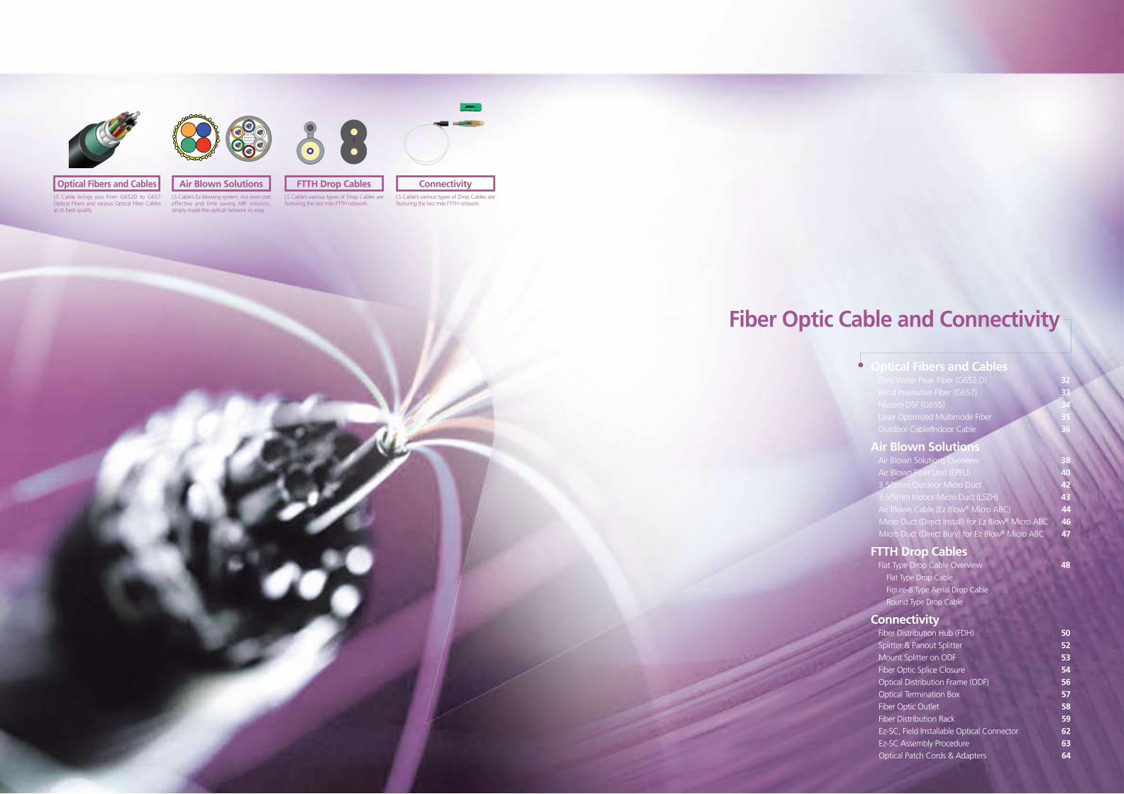
Fiber Optic Cable and Connectivity
Optical Fibers and Cables Zero Water Peak Fiber (G652.D) 32Bend Insensitive Fiber (G657) 33Nivzero DSF (G655) 34Laser Optimized Multimode Fiber 35Outdoor Cable/Indoor Cable 36
Air Blown Solutions Air Blown Solutions Overview 38Air Blown Fiber Unit (EPFU) 403.5/5mm Outdoor Micro Duct 42
3.5/5mm Indoor Micro Duct (LSZH) 43Air Blown Cable (Ez Blow® Micro ABC) 44Micro Duct (Direct Install) for Ez Blow® Micro ABC 46Micro Duct (Direct Bury) for Ez Blow® Micro ABC 47
FTTH Drop CablesFlat Type Drop Cable Overview 48
Flat Type Drop Cable
Figure-8 Type Aerial Drop Cable
Round Type Drop Cable
ConnectivityFiber Distribution Hub (FDH) 50Splitter & Panout Splitter 52Mount Splitter on ODF 53Fiber Optic Splice Closure 54Optical Distribution Frame (ODF) 56Optical Termination Box 57Fiber Optic Outlet 58Fiber Distribution Rack 59Ez-SC, Field Installable Optical Connector 62Ez-SC Assembly Procedure 63Optical Patch Cords & Adapters 64
Optical Fibers and CablesLS Cable brings you from G652D to G657 Optical Fibers and various Optical Fiber Cables at its best quality
ConnectivityLS Cable’s various types of Drop Cables are featuring the last mile FTTH network.
Air Blown SolutionsLS Cable’s Ez blowing system, our own cost effective and time saving ABF solution, simply made the optical network so easy.
FTTH Drop CablesLS Cable’s various types of Drop Cables are featuring the last mile FTTH network.
LS FTTH Solutions32 LS FTTH Solutions 33
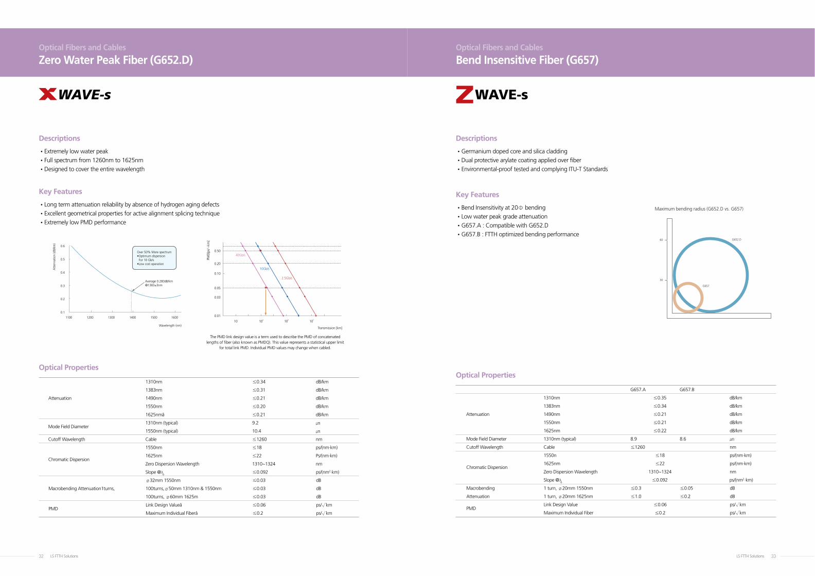
The PMD link design value is a term used to describe the PMD of concatenated lengths of fiber (also known as PMDQ). This value represents a statistical upper limit
for total link PMD. Individual PMD values may change when cabled.
1310nm ≤0.34 dB/km
1383nm ≤0.31 dB/km
Attenuation 1490nm ≤0.21 dB/km
1550nm ≤0.20 dB/km
1625nmâ ≤0.21 dB/km
Mode Field Diameter
1310nm (typical) 9.2 ㎛
1550nm (typical) 10.4 ㎛
Cutoff Wavelength Cable ≤1260 nm
1550nm ≤18 ps/(nm·km)
Chromatic Dispersion
1625nm ≤22 Ps/(nm·km)
Zero Dispersion Wavelength 1310~1324 nm
Slope @λo ≤0.092 ps/(nm2·km)
ø32mm 1550nm ≤0.03 dB
Macrobending Attenuation1turns, 100turns,ø50mm 1310nm & 1550nm ≤0.03 dB
100turns, ø60mm 1625m ≤0.03 dB
PMD
Link Design Valueâ ≤0.06 ps/√km
Maximum Individual Fiberâ ≤0.2 ps/√km
G657.A G657.B
1310nm ≤0.35 dB/km
1383nm ≤0.34 dB/km
Attenuation 1490nm ≤0.21 dB/km
1550nm ≤0.21 dB/km
1625nm ≤0.22 dB/km
Mode Field Diameter 1310nm (typical) 8.9 8.6 ㎛
Cutoff Wavelength Cable ≤1260 nm
1550n ≤18 ps/(nm·km)
Chromatic Dispersion
1625nm ≤22 ps/(nm·km)
Zero Dispersion Wavelength 1310~1324 nm
Slope @λo ≤0.092 ps/(nm2·km)
Macrobending 1 turn, ø20mm 1550nm ≤0.3 ≤0.05 dB
Attenuation 1 turn, ø20mm 1625nm ≤1.0 ≤0.2 dB
PMD
Link Design Value ≤0.06 ps/√km
Maximum Individual Fiber ≤0.2 ps/√km
Optical Fibers and Cables
Zero Water Peak Fiber (G652.D)Optical Fibers and Cables
Bend Insensitive Fiber (G657)
•Long term attenuation reliability by absence of hydrogen aging defects
•Excellent geometrical properties for active alignment splicing technique
•Extremely low PMD performance
•Bend Insensitivity at 20Φ bending
•Low water peak grade attenuation
•G657.A : Compatible with G652.D
•G657.B : FTTH optimized bending performance
•Extremely low water peak
•Full spectrum from 1260nm to 1625nm
•Designed to cover the entire wavelength
•Germanium doped core and silica cladding
•Dual protective arylate coating applied over fiber
•Environmental-proof tested and complying ITU-T Standards
Descriptions Descriptions
Key Features Key Features
Optical PropertiesOptical Properties
Average 0.280dB/km@1383±3nm
Over 50% More spectrum•Optimum dispersion For 10 Gb/s•Low cost operation
Wavelength (nm)
Att
enna
tion
(dB/
km)
160015001400130012001100
0.1
0.2
0.3
0.4
0.5
0.6
Transmission [km]
103 105 10710
0.01
0.03
0.05
0.10
0.20
0.5040Gb/s
10Gb/s
2.5Gb/s
PMD
[ps/
km
]
G657
G652.D60
30
Maximum bending radius (G652.D vs. G657)
WAVE-s WAVE-s
LS FTTH Solutions34 LS FTTH Solutions 35
A B
Attenuation
1550nm ≤0.22 dB/km
1625nm ≤0.24 dB/km
Mode Field Diameter 1310nm (typical) 9.6 9.3 ㎛
Cutoff Wavelength Cable ≤1480 nm
Chromatic Dispersion
1530~1565nm 2~6 5.5~10 ps/(nm·km)
Zero Dispersion Wavelength ≤1520 ≤1440 nm
PMD
Link Design Value ≤0.1 ps/√km
Maximum Individual Fiber ≤0.2 ps/√km
Characteristics Units 50㎛ 62.5um OM3 (50um)
Attenuation coefficient dB/km
850nm ≤2.4 ≤ 2.8 ≤2.4
1300nm ≤0.6 ≤ 0.7 ≤0.6
Bandwidth MHz.km
Premium
850nm / 1300nm ≥500 / 1000 ≥ 200 / 600 ≥1500 / 500
Standard
850nm / 1300nm ≥ 400 / 800 ≥140 / 400 ≥400 / 800
Laser Bandwidth MHz.km
850nm ≥2000
Numerical Aperture (typical) 0.2 0.275 0.2
DMD ps/m ≤0.30
10G Transmission m 300
Distance
Optical Fibers and Cables
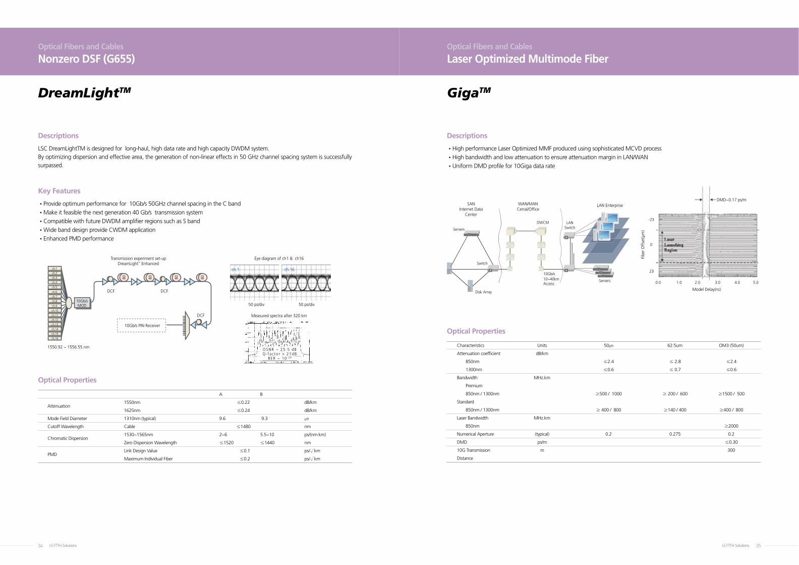
Nonzero DSF (G655)Optical Fibers and Cables
Laser Optimized Multimode Fiber
•Provide optimum performance for 10Gb/s 50GHz channel spacing in the C band
•Make it feasible the next generation 40 Gb/s transmission system
•Compatible with future DWDM amplifier regions such as S band
•Wide band design provide CWDM application
•Enhanced PMD performance
LSC DreamLightTM is designed for long-haul, high data rate and high capacity DWDM system.By optimizing dispersion and effective area, the generation of non-linear effects in 50 GHz channel spacing system is successfully surpassed.
• High performance Laser Optimized MMF produced using sophisticated MCVD process
• High bandwidth and low attenuation to ensure attenuation margin in LAN/WAN
• Uniform DMD profile for 10Giga data rate
Descriptions Descriptions
Key Features
Optical Properties
Optical Properties
10Gb/s
10Gb/s PIN Receiver
1550.92 ~ 1556.55 nm
Transmission experiment set-upDreamLightTM Enhanced
DCF
80 80 80 80
DCF
DCF
MOD
ch.1
ch.2
ch.3
ch.4
ch.5
ch.6
ch.7
ch.8
ch.9
ch.10
ch.11
ch.12
ch.13
ch.14
ch.15
ch.16
OSNR ~ 25 .5 dBQ- f a c to r > 21dB
BER ~ 10 -29
Measured spectra after 320 km
Eye diagram of ch1 & ch16
50 ps/div 50 ps/div
ch.1 ch.1610Gb/s10~40kmAccess
LAN EnterpriseWAN/MANCerral/Office
SANInternet Data
Center
LANSwitch
Switch
Disk Array
Servers
Servers
DWCM
DMD~0.17 ps/m
Fibe
r O
ffse
t(µm
)
Model Delay(ns)
0
-23
23
0.0 1.0 2.0 3.0 4.0 5.0
DreamLightTM GigaTM
LS FTTH Solutions36 LS FTTH Solutions 37
Type Construction Fiber count Feature
Type Construction Fiber count Feature
Type Construction Fiber count Feature
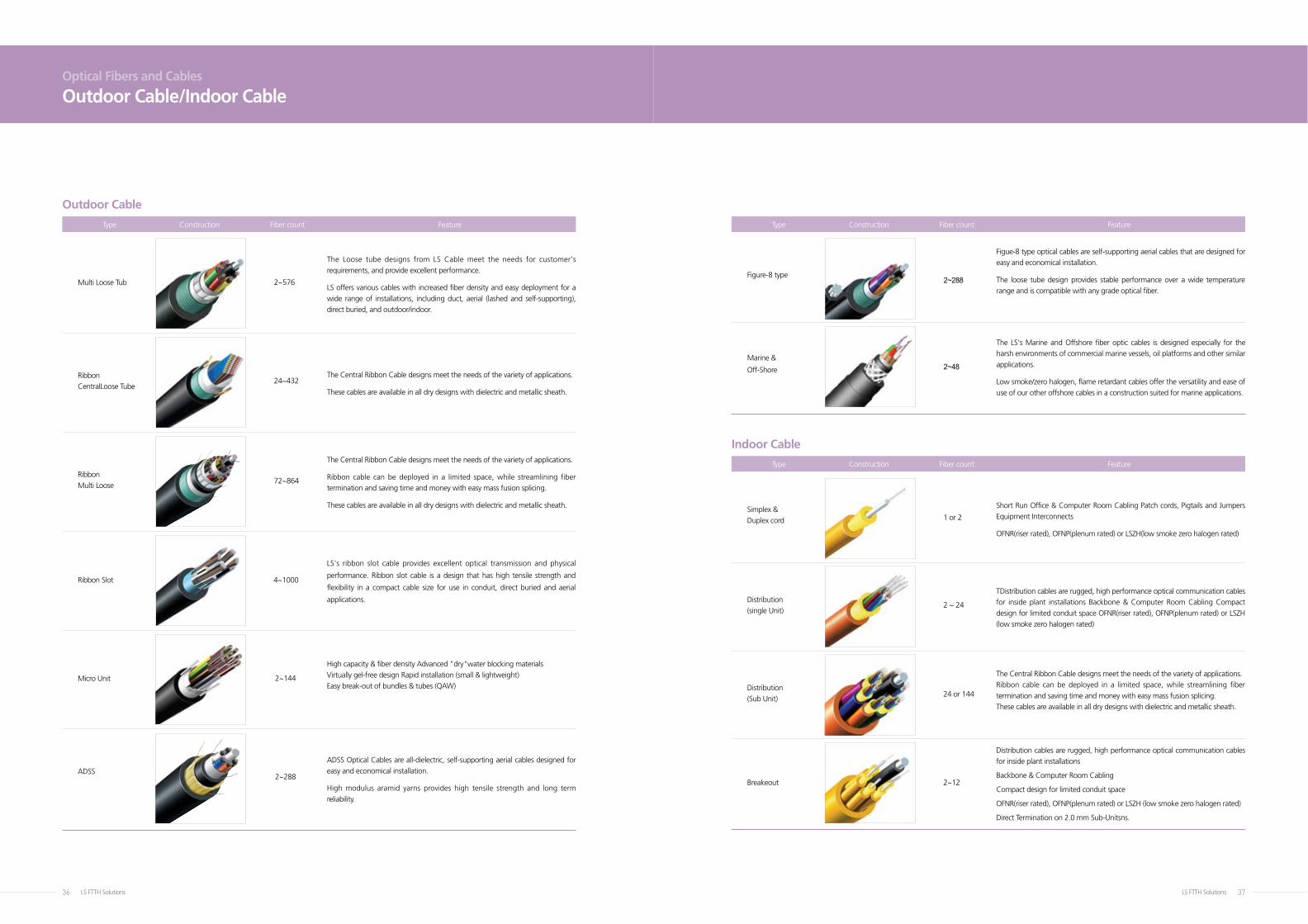
4~1000
LS's ribbon slot cable provides excellent optical transmission and physical
performance. Ribbon slot cable is a design that has high tensile strength and
flexibility in a compact cable size for use in conduit, direct buried and aerial
applications.
Ribbon Slot
2~48Marine &
Off-Shore
The LS's Marine and Offshore fiber optic cables is designed especially for the
harsh environments of commercial marine vessels, oil platforms and other similar
applications.
Low smoke/zero halogen, flame retardant cables offer the versatility and ease of
use of our other offshore cables in a construction suited for marine applications.
2~576
The Loose tube designs from LS Cable meet the needs for customer's
requirements, and provide excellent performance.
LS offers various cables with increased fiber density and easy deployment for a
wide range of installations, including duct, aerial (lashed and self-supporting),
direct buried, and outdoor/indoor.
Multi Loose Tub
2~144Micro Unit
High capacity & fiber density Advanced "dry"water blocking materials
Virtually gel-free design Rapid installation (small & lightweight)
Easy break-out of bundles & tubes (QAW)
24~432 The Central Ribbon Cable designs meet the needs of the variety of applications.
These cables are available in all dry designs with dielectric and metallic sheath.
Ribbon
CentralLoose Tube
2~288ADSS
ADSS Optical Cables are all-dielectric, self-supporting aerial cables designed for
easy and economical installation.
High modulus aramid yarns provides high tensile strength and long term
reliability.
72~864
The Central Ribbon Cable designs meet the needs of the variety of applications.
Ribbon cable can be deployed in a limited space, while streamlining fiber
termination and saving time and money with easy mass fusion splicing.
These cables are available in all dry designs with dielectric and metallic sheath.
Ribbon
Multi Loose
2~288Figure-8 type
Figue-8 type optical cables are self-supporting aerial cables that are designed for
easy and economical installation.
The loose tube design provides stable performance over a wide temperature
range and is compatible with any grade optical fiber.
Optical Fibers and Cables
Outdoor Cable/Indoor Cable
2~12
Distribution cables are rugged, high performance optical communication cables
for inside plant installations
Backbone & Computer Room Cabling
Compact design for limited conduit space
OFNR(riser rated), OFNP(plenum rated) or LSZH (low smoke zero halogen rated)
Direct Termination on 2.0 mm Sub-Unitsns.
Breakeout
1 or 2
Short Run Office & Computer Room Cabling Patch cords, Pigtails and Jumpers
Equipment Interconnects
OFNR(riser rated), OFNP(plenum rated) or LSZH(low smoke zero halogen rated)
Simplex &
Duplex cord
2 ~ 24
TDistribution cables are rugged, high performance optical communication cables
for inside plant installations Backbone & Computer Room Cabling Compact
design for limited conduit space OFNR(riser rated), OFNP(plenum rated) or LSZH
(low smoke zero halogen rated)
Distribution
(single Unit)
24 or 144
The Central Ribbon Cable designs meet the needs of the variety of applications.
Ribbon cable can be deployed in a limited space, while streamlining fiber
termination and saving time and money with easy mass fusion splicing.
These cables are available in all dry designs with dielectric and metallic sheath.
Distribution
(Sub Unit)
Outdoor Cable
Indoor Cable
LS FTTH Solutions38 LS FTTH Solutions 39
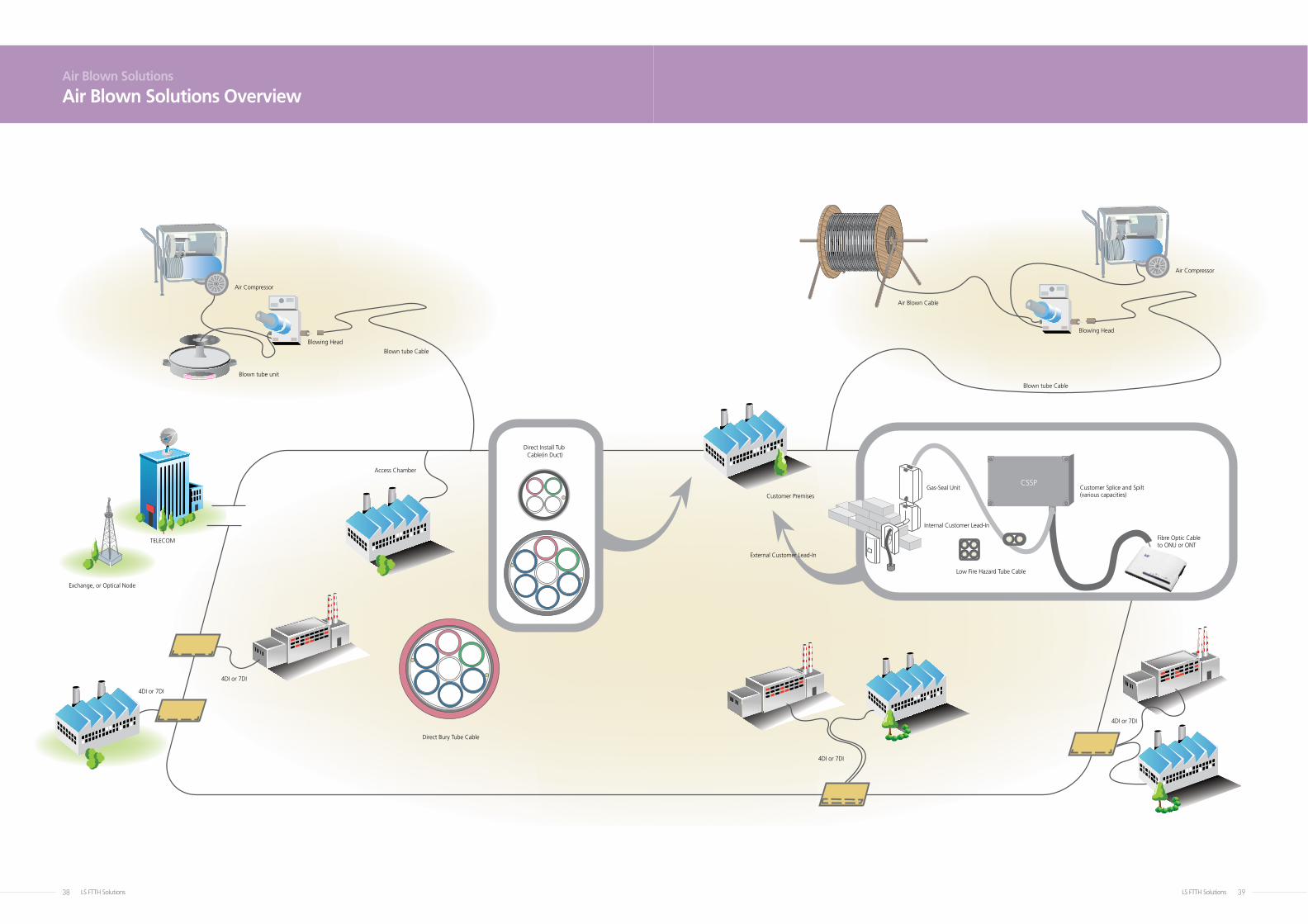
Air Blown Solutions
Air Blown Solutions Overview
Customer Splice and Spilt(various capacities)
Fibre Optic Cableto ONU or ONT
CSSPGas-Seal Unit
Internal Customer Lead-In
Access Chamber
Air Compressor
Blown tube unit
Blown tube Cable
Blown tube Cable
Blowing Head
Air Compressor
Air Blown Cable
Blowing Head
Direct Bury Tube Cable
4DI or 7DI
Customer Premises
Exchange, or Optical Node
TELECOM
4DI or 7DI
4DI or 7DI
4DI or 7DI
Low Fire Hazard Tube Cable
External Customer Lead-In
Direct Install Tub Cable(in Duct)
LS FTTH Solutions40 LS FTTH Solutions 41
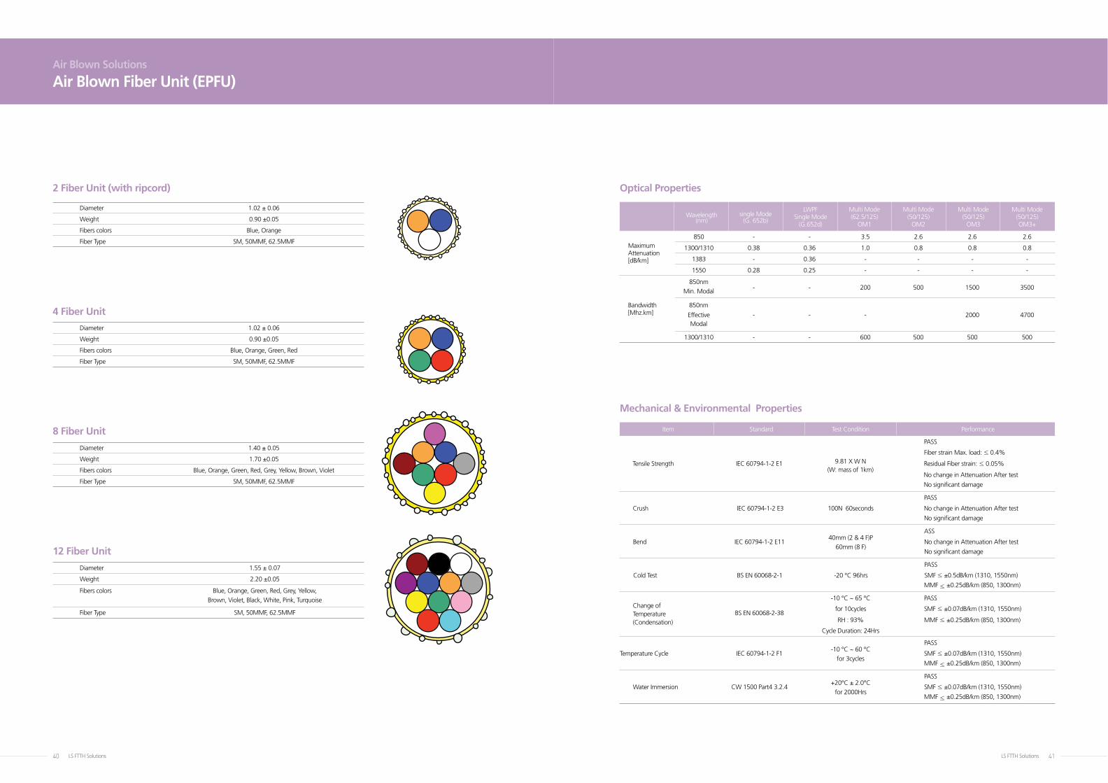
2 Fiber Unit (with ripcord)
Diameter 1.02 ± 0.06
Weight 0.90 ±0.05
Fibers colors Blue, Orange
Fiber Type SM, 50MMF, 62.5MMF
4 Fiber Unit
Diameter 1.02 ± 0.06
Weight 0.90 ±0.05
Fibers colors Blue, Orange, Green, Red
Fiber Type SM, 50MMF, 62.5MMF
8 Fiber Unit
Diameter 1.40 ± 0.05
Weight 1.70 ±0.05
Fibers colors Blue, Orange, Green, Red, Grey, Yellow, Brown, Violet
Fiber Type SM, 50MMF, 62.5MMF
12 Fiber Unit
Diameter 1.55 ± 0.07
Weight 2.20 ±0.05
Fibers colors Blue, Orange, Green, Red, Grey, Yellow,
Brown, Violet, Black, White, Pink, Turquoise
Fiber Type SM, 50MMF, 62.5MMF
Wavelength
single Mode
LWPF Multi Mode Multi Mode Multi Mode Multi Mode
(nm)
(G. 652b) Single Mode (62.5/125) (50/125) (50/125) (50/125)
(G.652d) OM1 OM2 OM3 OM3+
PASS
Fiber strain Max. load: ≤ 0.4%
Tensile Strength IEC 60794-1-2 E1 9.81 X W N Residual Fiber strain: ≤ 0.05%
(W: mass of 1km)
No change in Attenuation After test
No significant damage
PASS
Crush IEC 60794-1-2 E3 100N 60seconds No change in Attenuation After test
No significant damage
40mm (2 & 4 F)P
ASS
Bend IEC 60794-1-2 E11 60mm (8 F)
No change in Attenuation After test
No significant damage
PASS
Cold Test BS EN 60068-2-1 -20 °C 96hrs SMF ≤ ±0.5dB/km (1310, 1550nm)
MMF ≤ ±0.25dB/km (850, 1300nm)
Change of
-10 °C ~ 65 °C PASS
Temperature
BS EN 60068-2-38
for 10cycles SMF ≤ ±0.07dB/km (1310, 1550nm)
(Condensation) RH : 93% MMF ≤ ±0.25dB/km (850, 1300nm)
Cycle Duration: 24Hrs
-10 °C ~ 60 °C
PASS
Temperature Cycle IEC 60794-1-2 F1 for 3cycles
SMF ≤ ±0.07dB/km (1310, 1550nm)
MMF ≤ ±0.25dB/km (850, 1300nm)
+20°C ± 2.0°C
PASS
Water Immersion CW 1500 Part4 3.2.4 for 2000Hrs
SMF ≤ ±0.07dB/km (1310, 1550nm)
MMF ≤ ±0.25dB/km (850, 1300nm)
Item Standard Test Condition Performance
Air Blown Solutions
Air Blown Fiber Unit (EPFU)
Optical Properties
Mechanical & Environmental Properties
Maximum
850 - - 3.5 2.6 2.6 2.6
Attenuation
1300/1310 0.38 0.36 1.0 0.8 0.8 0.8
[dB/km] 1383 - 0.36 - - - -
1550 0.28 0.25 - - - -
850nm - - 200 500 1500 3500
Min. Modal
Bandwidth 850nm [Mhz.km] Effective - - - 2000 4700
Modal
1300/1310 - - 600 500 500 500
LS FTTH Solutions42 LS FTTH Solutions 43
No. of Tube Nom. O.D. Min. Bend Tensile Nom. Weight Max. Drum
(mm) Radius (mm) (N) (kg) Length (m)
1 8.4 85 500 50 4000
2 8.5 X 13.5 135 800 78 4000
4 15.4 300 1200 121 4000
7 18.5 280 1700 167 4000
12 23.7 355 2500 247 2000
19 27.8 420 3300 338 2000
24 33.0 500 3800 440 2000
No. of Tube Nom. O.D. Min. Bend Tensile Nom. Weight Max. Drum
(mm) Radius (mm) (N) (kg) Length (m)
1 10.0 85 600 67 4000
2 10.5X15.5 135 800 115 4000
4 19.4 300 1500 162 4000
7 22.3 280 1800 208 4000
12 28.3 355 2700 377 2000
19 31.1 420 3500 485 2000
24 36.8 500 4400 560 2000
Item Standard Test Condition Performance
Applied load PASS
Tensile Strength IEC 60794-1-2 E1
refer to Tensile No permanent damage, or localized
above Table diameter reductions greater than 7%
5 minute
700N 60seconds for PASS
Crush IEC 60794-1 E2 Direct In stall type No permanent residual deformation
and 1,000N 60seconds for greater than 15%, no splitting,
Direct In Bury type nor permanent damage
Air Blown Solutions
3.5/5mm Out door Micro DuctAir Blown Solutions
3.5/5mm Indoor Micro Duct (LSZH)
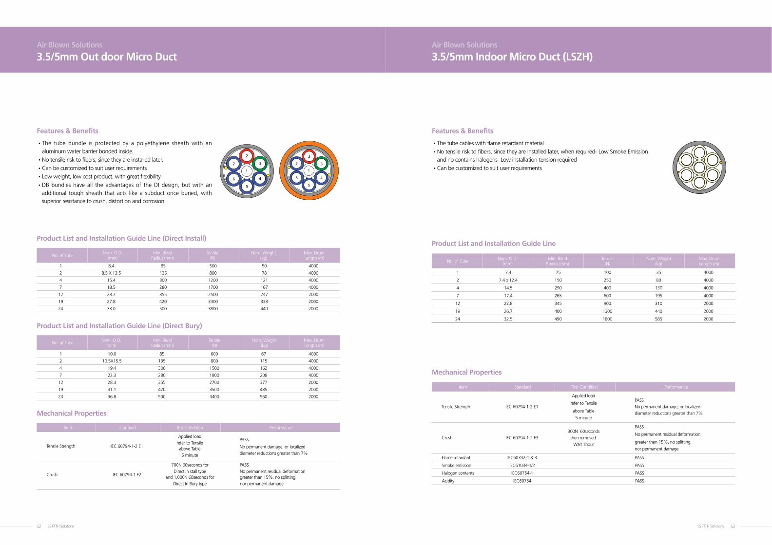
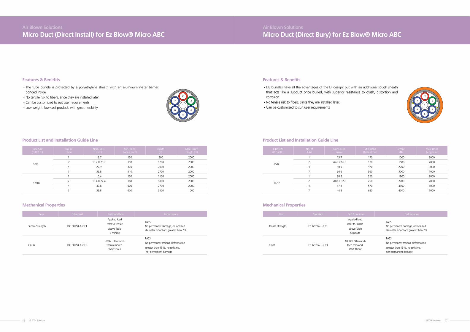
• The tube bundle is protected by a polyethylene sheath with an aluminum water barrier bonded inside.
• No tensile risk to fibers, since they are installed later.
•Can be customized to suit user requirements
•Low weight, low cost product, with great flexibility
• DB bundles have all the advantages of the DI design, but with an additional tough sheath that acts like a subduct once buried, with superior resistance to crush, distortion and corrosion.
Features & Benefits
Product List and Installation Guide Line (Direct Install)
Product List and Installation Guide Line (Direct Bury)
Mechanical Properties
1
2
3
4
5
6
7
1
2
3
4
5
6
7
•The tube cables with flame retardant material
• No tensile risk to fibers, since they are installed later, when required- Low Smoke Emission and no contains halogens- Low installation tension required
•Can be customized to suit user requirements
Features & Benefits
Mechanical Properties
Product List and Installation Guide Line
No. of Tube Nom. O.D. Min. Bend Tensile Nom. Weight Max. Drum
(mm) Radius (mm) (N) (kg) Length (m)
1 7.4 75 100 35 4000
2 7.4 x 12.4 150 250 80 4000
4 14.5 290 400 130 4000
7 17.4 265 600 195 4000
12 22.8 345 900 310 2000
19 26.7 400 1300 440 2000
24 32.5 490 1800 585 2000
Item Standard Test Condition Performance
Applied load PASS
Tensile Strength IEC 60794-1-2 E1
refer to Tensile No permanent damage, or localized
above Table diameter reductions greater than 7% 5 minute
300N 60seconds
PASS
Crush IEC 60794-1-2 E3
then removed. No permanent residual deformation
Wait 1hour greater than 15%, no splitting,
nor permanent damage
Flame retardant IEC60332-1 & 3 PASS
Smoke emission IEC61034-1/2 PASS
Halogen contents IEC60754-1 PASS
Acidity IEC60754 PASS
1
2
3
4
5
6
7
1
2
3
4
5
6
7
LS FTTH Solutions44 LS FTTH Solutions 45
Standard Reel Length 4000m
* Other Cable lengths may be available upon request.
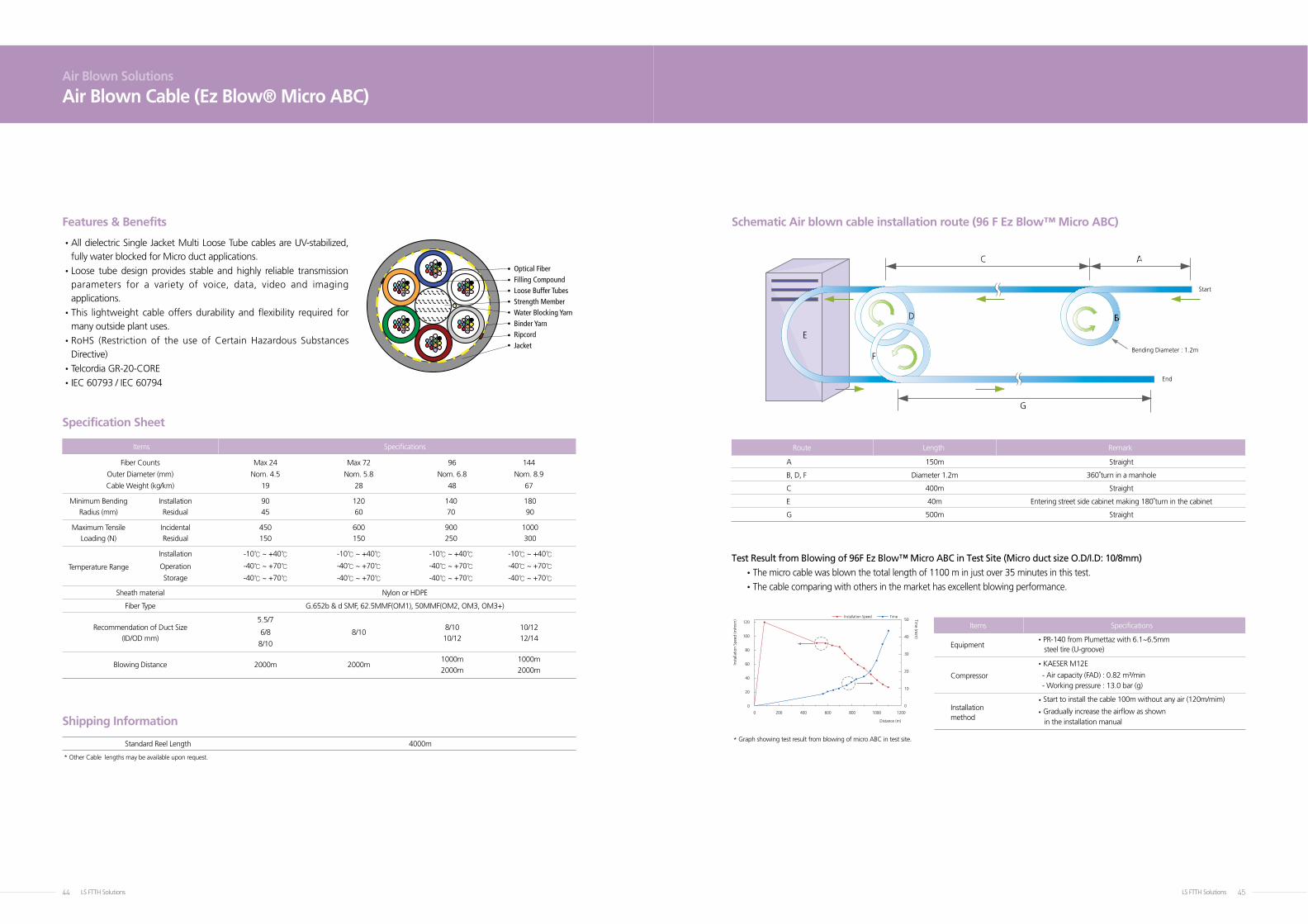
* Graph showing test result from blowing of micro ABC in test site.
Test Result from Blowing of 96F Ez Blow™ Micro ABC in Test Site (Micro duct size O.D/I.D: 10/8mm)
•The micro cable was blown the total length of 1100 m in just over 35 minutes in this test.
•The cable comparing with others in the market has excellent blowing performance.
Schematic Air blown cable installation route (96 F Ez Blow™ Micro ABC)
Items Specifications
Items Specifications
Equipment
•PR-140 from Plumettaz with 6.1~6.5mm
steel tire (U-groove)
•KAESER M12E
Compressor - Air capacity (FAD) : 0.82 m³/min
- Working pressure : 13.0 bar (g)
Installation
•Start to install the cable 100m without any air (120m/mim)
method
• Gradually increase the airflow as shown
in the installation manual
Route Length Remark
A 150m Straight
B, D, F Diameter 1.2m 360°turn in a manhole
C 400m Straight
E 40m Entering street side cabinet making 180°turn in the cabinet
G 500m Straight
Air Blown Solutions
Air Blown Cable (Ez Blow® Micro ABC)
• All dielectric Single Jacket Multi Loose Tube cables are UV-stabilized, fully water blocked for Micro duct applications.
• Loose tube design provides stable and highly reliable transmission parameters for a variety of voice, data, video and imaging applications.
• This lightweight cable offers durability and flexibility required for many outside plant uses.
• RoHS (Restriction of the use of Certain Hazardous Substances Directive)
•Telcordia GR-20-CORE
•IEC 60793 / IEC 60794
Features & Benefits
Specification Sheet
Shipping Information
Fiber Counts Max 24 Max 72 96 144
Outer Diameter (mm) Nom. 4.5 Nom. 5.8 Nom. 6.8 Nom. 8.9
Cable Weight (kg/km) 19 28 48 67
Minimum Bending Installation 90 120 140 180
Radius (mm) Residual 45 60 70 90
Maximum Tensile Incidental 450 600 900 1000
Loading (N) Residual 150 150 250 300
Installation -10℃ ~ +40℃ -10℃ ~ +40℃ -10℃ ~ +40℃ -10℃ ~ +40℃
Temperature Range Operation -40℃ ~ +70℃ -40℃ ~ +70℃ -40℃ ~ +70℃ -40℃ ~ +70℃
Storage -40℃ ~ +70℃ -40℃ ~ +70℃ -40℃ ~ +70℃ -40℃ ~ +70℃
Sheath material Nylon or HDPE
Fiber Type G.652b & d SMF, 62.5MMF(OM1), 50MMF(OM2, OM3, OM3+)
Recommendation of Duct Size
5.5/7 8/10 10/12
(ID/OD mm)
6/8 8/10 10/12 12/14
8/10
Blowing Distance 2000m 2000m
1000m 1000m
2000m 2000m
Distance (m)
Installation Speed Time
Inst
alla
tion
Spee
d (m
/mim
) Time (m
im)
1000 12008006004002000
0
20
40
60
80
100
0
10
20
30
40
50120
Bending Diameter : 1.2m
Start
End
Optical FiberFilling CompoundLoose Buffer TubesStrength MemberWater Blocking YarnBinder YarnRipcordJacket
LS FTTH Solutions46 LS FTTH Solutions 47
Tube Size No. of Nom. O.D. Min. Bend Tensile Max. Drum (O.D./I.D.) Tube (mm) Radius (mm) (N) Length (m)
Tube Size No. of Nom. O.D. Min. Bend Tensile Max. Drum (O.D./I.D.) Tube (mm) Radius (mm) (N) Length (m)
1 13.7 150 800 2000
10/8
2 13.7 X 23.7 150 1200 2000
4 27.9 420 2000 2000
7 33.8 510 2700 2000
1 15.4 160 1100 2000
12/10
2 15.4 X 27.4 160 1800 2000
4 32.8 500 2700 2000
7 39.8 600 3500 1000
1 13.7 170 1000 2000
10/8
2 26.6 X 16.6 170 1500 2000
4 30.9 470 2200 2000
7 36.6 560 3000 1000
1 20.8 250 1800 2000
12/10
2 20.8 X 32.8 250 2700 2000
4 37.8 570 3300 1000
7 44.8 680 4700 1000
Air Blown Solutions
Micro Duct (Direct Install) for Ez Blow® Micro ABCAir Blown Solutions
Micro Duct (Direct Bury) for Ez Blow® Micro ABC
• The tube bundle is protected by a polyethylene sheath with an aluminum water barrier bonded inside.
• No tensile risk to fibers, since they are installed later.
• Can be customized to suit user requirements
• Low weight, low cost product, with great flexibility
• DB bundles have all the advantages of the DI design, but with an additional tough sheath that acts like a subduct once buried, with superior resistance to crush, distortion and corrosion.
• No tensile risk to fibers, since they are installed later.
•Can be customized to suit user requirements
Features & Benefits Features & Benefits
Product List and Installation Guide Line Product List and Installation Guide Line
Mechanical Properties Mechanical Properties
Item Standard Test Condition Performance
Applied load PASS
Tensile Strength IEC 60794-1-2 E1
refer to Tensile No permanent damage, or localized
above Table diameter reductions greater than 7% 5 minute
700N 60seconds
PASS
Crush IEC 60794-1-2 E3
then removed.
No permanent residual deformation
Wait 1hour greater than 15%, no splitting,
nor permanent damage
Item Standard Test Condition Performance
Applied load PASS
Tensile Strength IEC 60794-1-2 E1
refer to Tensile No permanent damage, or localized
above Table diameter reductions greater than 7% 5 minute
1000N 60seconds
PASS
Crush IEC 60794-1-2 E3
then removed.
No permanent residual deformation
Wait 1hour greater than 15%, no splitting,
nor permanent damage
1
2
3
4
5
6
7
1
2
3
4
5
6
7
1
2
3
4
5
6
7
1
2
3
4
5
6
7
LS FTTH Solutions48 LS FTTH Solutions 49
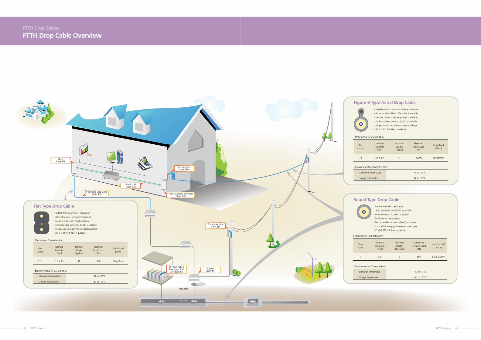
FTTH Drop Cables
FTTH Drop Cable Overview
Round Type Drop Cable
Fiber
Count
1
Nominal
Diameter
[mm]
3.0
Nominal
Weight
[kg/km]
8
Maximum
Tensile Load
[N]
500
Crush Load
[N/cm]
50kg/50mm
I Mechanical Characteristics
I Environmental Characteristics
Operation Temperature - 40 to +70°C
Storage Temperature - 40 to +70°C
- Suitable In/outdoor application
(Duct and Aerial Installation is possible)
- Flame Retardant PU jacket is applied
- Small size and light weight
- Field installable connector (Ez-SC) is available
- It is possible to supply Pre-connectorized type
- ITU-T G.657A, B fiber is available
Figure-8 Type Aerial Drop Cable
I Mechanical Characteristics
I Environmental Characteristics
Operation Temperature - 40 to +70°C
Storage Temperature - 40 to +70°C
- Suitable outdoor application (Aerial Installation)
- Flame Retardant PU or LSZH jacket is available
- Metal or dielectric messenger wire is available
- Field installable connector (Ez-SC) is available
- It is possible to supply Pre-connectorized type
- ITU-T G.657A, B fiber is available
Flat Type Drop Cable
Fiber
Count
1, 2
Nominal
Diameter[mm]
1.9 x 3.5
Nominal
Weight[kg/km]
10
Maximum
Tensile Load[N]
150
Crush Load
[N/cm]
50kg/50mm
I Mechanical Characteristics
I Environmental Characteristics
Operation Temperature - 20 to +70°C
Storage Temperature - 30 to +70°C
- Suitable for Indoor & duct application
- Flame Retardant LSZH jacket is applied
- Excellent crush and impact resistance
- Field installable connector (Ez-SC) is available
- It is possible to supply Pre-connectorized type
- ITU-T G.657A, B fiber is available
Outet(page 60)
Patch cord(page 표시)
Filed Installable connector(page 61)
Termination Box(page 59)
Closure(page 56)
Terminal Box(page 표시)
Patch cord Drop Cable(page 63)
Fiber
Count
1, 2
Nominal
Diameter[mm]
5.0 x 2.9
Nominal
Weight[kg/km]
11
Maximum
Tensile Load[N]
1000N
Crush Load
[N/cm]
50kg/50mm
Closure
Manhole
Street Cabinet
PDF (page 표시)Rack (page 표시)ODF (page 58)
LS FTTH Solutions50 LS FTTH Solutions 51
FODH Series
PARAMETER FODH-288-A FODH-432-A
Dimension(H x W x D) 1100mm x 720mm x 520mm 990mm x 1320mm x 520mm
Max. Capacity 288 432
No. of Splitter Module 12 24
Splitter Module Type 1:4 / 1:8 / 1:16 / 1:32
Cable port(In/Out) 1/2 2/4
Cable Diameter Max.20 mm
Adaptor Type SC / FC
No. of Adaptor 288 432
Input Parking Lot Max.12 Max.24
Output Parking Lot Max.48 Max.96
Material Aluminum
Mounting Options Ground / Pedestal / Pole
Part Number ODFH-SPMD - ① - ②
Material
Stainless Steel
Module (*other material available)
Case Dimension 150 x 80 x 15
(L x W x D, mm) (*other type available)
Connector Type
SC/APC
(*other type available)
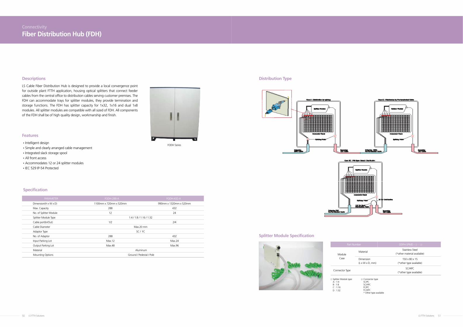
Connectivity
Fiber Distribution Hub (FDH)
•Intelligent design
•Simple and clearly arranged cable management
•Integrated slack storage spool
•All front access
•Accommodates 12 or 24 splitter modules
•IEC 529 IP-54 Protected
LS Cable Fiber Distribution Hub is designed to provide a local convergence point for outside plant FTTH application, housing optical splitters that connect feeder cables from the central office to distribution cables serving customer premises. The FDH can accommodate trays for splitter modules, they provide termination and storage functions. The FDH has splitter capacity for 1x32, 1x16 and dual 1x8 modules. All splitter modules are compatible with all sized of FDH. All components of the FDH shall be of high quality design, workmanship and finish.
Descriptions Distribution Type
Splitter Module Specification
Features
Specification
① Splitter Module type A : 1:4 B : 1:8 C : 1:16 D : 1:32
② Connector type SC/PC SC/APC FC/PC FC/APC * Other type available
LS FTTH Solutions52 LS FTTH Solutions 53
•FTTH, FTTB, FTTC
•CATV networks
•PON (Passive Optical Network) System
•Fiber Optic Equipment and System
•Same as LS’s Panout Splitter
Connectivity
Splitter & Panout SplitterConnectivity
Mount Splitter on ODF
LS Cable supply high performance PLC (Planar Lightwave Circuit) Splitter Modules which are GR-1209-CORE, GR-1221-CORE requirements compliant. A single mode 1 x N Splitter has one input port and output ports (N) for dividing an optical signal.
• Rackmount Type Splitter is FTTH-Ready component and useful to set-up at a rack type system in a central office such as Equipment Room (ER) or Telecommunication Room (TR).
• There is no need to handle splitter module or optical fiber because all components are inside the frame.
• It includes a splitter inside the rackmount. (4ch, 8ch, 16ch, 32ch available)
•Low Insertion Loss
•Good Uniformity
•Wide Operation Wavelength Range
•Ultra Small Design
•Low P01
•GR-1209 & 1221-CORE Compliant
•Fine Tuning of FHD & PECVD
•Same as LS’s Panout Splitter
•Fiber Termination/Connection Ports Option
•Optical Splice Capability
•Compact Design
•Compatible with most cable management system
Descriptions Descriptions
Key Features
Key Features
Applications
Applications
Part Number
Model FOSP1x4 FOSP1x8 FOSP1x16 FOSP1x32 FOSP1x64 FOSP2x4 FOSP2x8 FOSP2x16 FOSP2x32
Specification Sheet
1xN or 2xN 1 x 4 1 x 8 1 x 16 1 x 32 1 x 64 2 x 4 2 x 8 2 x 16 2 x 32
Packing
40 x 4 x 4 50 x 5 x 4 40 x 4 x4
Size (mm)
40 x 4 x 4 or or 55 x 7 x 4 70 x 22 x 8 40 x 4 x 4 or 50 x 5 x 4 60 x 7 x 4 50 x 5 x 4 55 x 7 x 4 50 x 5 x 4
Return Loss ≥ 55dB
Directivity ≥ 55dB
Operating 1.26 ~ 1.60 ㎛
Wavelength
Temperature -40 ~ 80℃
Pigtails
Input 250 ㎛ dia. and output/ribbon fiber normal length :
1m or customer specified (un-connectorized or connectorized)
① Mount type S: Splitter
F: PANOUT type splitter
R: mount Splitter on Rack mount ODF
W: mount Splitter on wall mount cassette
C: mount Splitter on closure tray
② In x out 1x4
1x8
1x16
1x32
1x64
2x4
2x8
2x16
2x32
③ Connector TypeN : None
LC : LC Simplex DLC : LC Duplex
SC : SC Simplex DSC : SC Duplex
ST : ST Simplex FC : FC Simplex
MU : MU Simplex
④ Polishing typeSP : PC or SPC (RL ≥40dB) for SM
UP : UPC (RL ≥55dB) for SM
AP : APC (RL ≥60dB) for SM
FOSP-①-②-③④
1XN Splitter Chip
1ch Silcon Fiber array
Silcon Molding
Nch Slicon Fiber arrayLid
LS FTTH Solutions54 LS FTTH Solutions 55
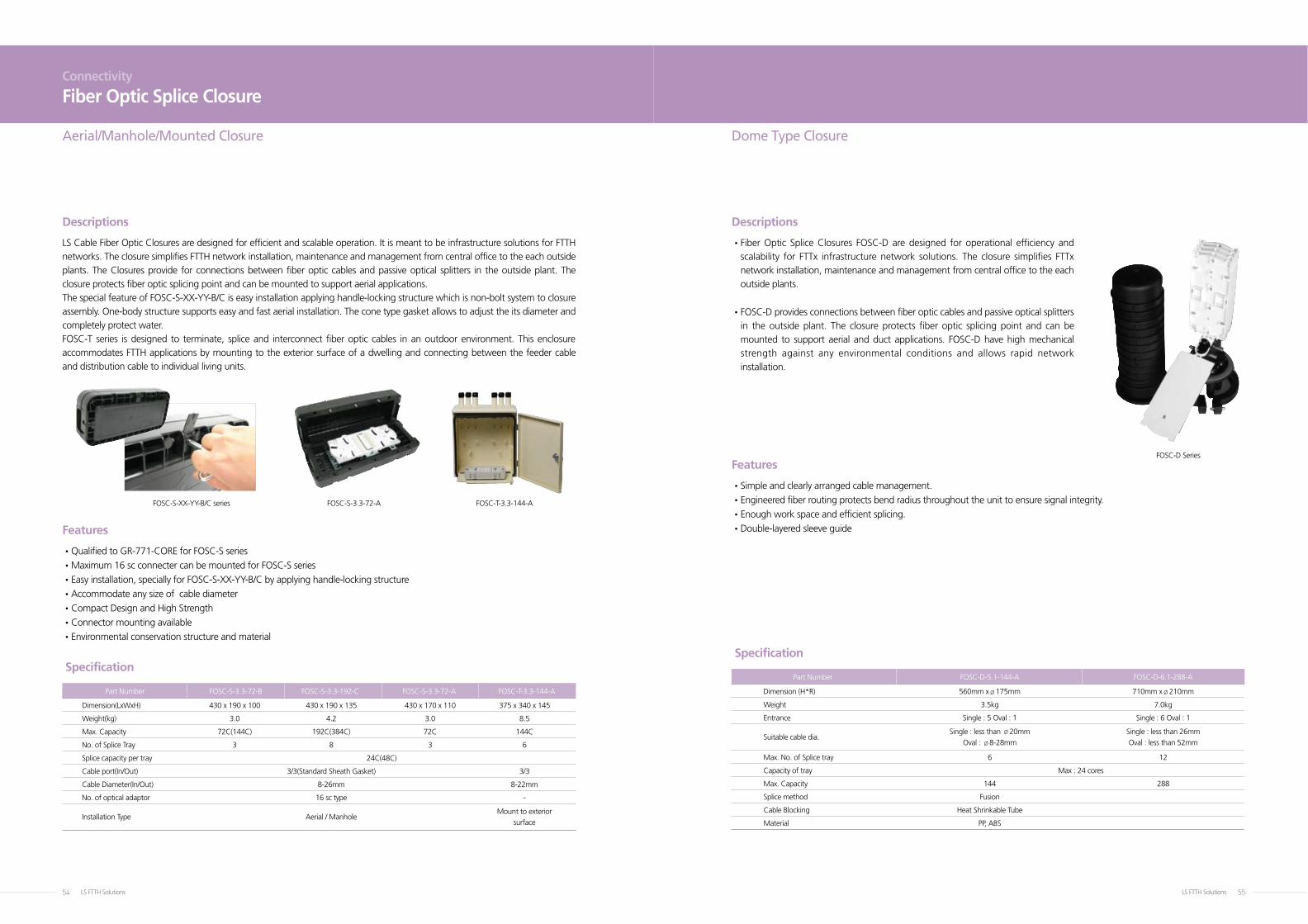
Part Number FOSC-D-5.1-144-A FOSC-D-6.1-288-A
Dimension (H*R) 560mm xø175mm 710mm xø210mm
Weight 3.5kg 7.0kg
Entrance Single : 5 Oval : 1 Single : 6 Oval : 1
Suitable cable dia.
Single : less than ø20mm Single : less than 26mm
Oval : ø8-28mm Oval : less than 52mm
Max. No. of Splice tray 6 12
Capacity of tray Max : 24 cores
Max. Capacity 144 288
Splice method Fusion
Cable Blocking Heat Shrinkable Tube
Material PP, ABS
Aerial/Manhole/Mounted Closure Dome Type Closure
Part Number FOSC-S-3.3-72-B FOSC-S-3.3-192-C FOSC-S-3.3-72-A FOSC-T-3.3-144-A
Dimension(LxWxH) 430 x 190 x 100 430 x 190 x 135 430 x 170 x 110 375 x 340 x 145
Weight(kg) 3.0 4.2 3.0 8.5
Max. Capacity 72C(144C) 192C(384C) 72C 144C
No. of Splice Tray 3 8 3 6
Splice capacity per tray 24C(48C)
Cable port(In/Out) 3/3(Standard Sheath Gasket) 3/3
Cable Diameter(In/Out) 8-26mm 8-22mm
No. of optical adaptor 16 sc type -
Installation Type Aerial / Manhole
Mount to exterior
surface
Connectivity
Fiber Optic Splice Closure
LS Cable Fiber Optic Closures are designed for efficient and scalable operation. It is meant to be infrastructure solutions for FTTH networks. The closure simplifies FTTH network installation, maintenance and management from central office to the each outside plants. The Closures provide for connections between fiber optic cables and passive optical splitters in the outside plant. The closure protects fiber optic splicing point and can be mounted to support aerial applications. The special feature of FOSC-S-XX-YY-B/C is easy installation applying handle-locking structure which is non-bolt system to closure assembly. One-body structure supports easy and fast aerial installation. The cone type gasket allows to adjust the its diameter and completely protect water.FOSC-T series is designed to terminate, splice and interconnect fiber optic cables in an outdoor environment. This enclosure accommodates FTTH applications by mounting to the exterior surface of a dwelling and connecting between the feeder cable and distribution cable to individual living units.
• Fiber Optic Splice Closures FOSC-D are designed for operational efficiency and scalability for FTTx infrastructure network solutions. The closure simplifies FTTx network installation, maintenance and management from central office to the each outside plants.
• FOSC-D provides connections between fiber optic cables and passive optical splitters in the outside plant. The closure protects fiber optic splicing point and can be mounted to support aerial and duct applications. FOSC-D have high mechanical strength against any environmental conditions and allows rapid network installation.
•Qualified to GR-771-CORE for FOSC-S series
•Maximum 16 sc connecter can be mounted for FOSC-S series
•Easy installation, specially for FOSC-S-XX-YY-B/C by applying handle-locking structure
•Accommodate any size of cable diameter
•Compact Design and High Strength
•Connector mounting available
•Environmental conservation structure and material
•Simple and clearly arranged cable management.
•Engineered fiber routing protects bend radius throughout the unit to ensure signal integrity.
•Enough work space and efficient splicing.
•Double-layered sleeve guide
Descriptions Descriptions
Features
Features
Specification Specification
FOSC-S-XX-YY-B/C series FOSC-S-3.3-72-A FOSC-T-3.3-144-A
FOSC-D Series
LS FTTH Solutions56 LS FTTH Solutions 57
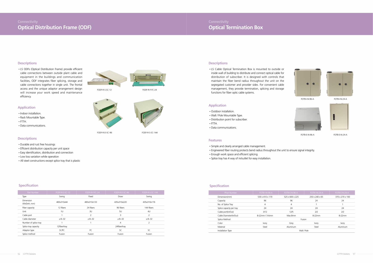
Part Number FODF-R-S-SC-12 FODF-R-F-FC-24 FODF-R-D-SC-96 FODF-R-S-SC-144
Type Swing Fixed Draw Swing
Dimension 483x310x44 483x310x133 435x310x220 435x310x176
(WxDxH, mm)
Fiber capacity 12 fibers 24 fibers 96 fibers 144 fibers
Unit 1U 3U 5U 4U
Cable port 1 2 3 2
Cable diameter ø8~32 ø8~32 ø8~32 ø8~32
Number of splice tray 1 1 4 2
Splice tray capacity 12fiber/tray 24fiber/tray
Adaptor type SC/FC FC SC SC
Splice method Fusion Fusion Fusion Fusion
Connectivity
Optical Distribution Frame (ODF)Connectivity
Optical Termination Box
• LS ODFs (Optical Distribution Frame) provide efficient cable connections between outside plant cable and equipment in the buildings and communication facilities, ODF integrates fiber splicing, storage and cable connections together in single unit. The frontal access and the unique adaptor arrangement design will increase your work speed and maintenance efficiency.
• LS Cable Optical Termination Box is mounted to outside or inside wall of building to distribute and connect optical cable for distribution of subscriber. It is designed with controls that maintain the fiber bend radius throughout the unit on the segregated customer and provider sides. For convenient cable management, they provide termination, splicing and storage functions for fiber optic cable systems.
•Durable and rust free housings
•Efficient distribution capacity per unit space
•Easy identification, distribution and connection
•Low loss variation while operation
•All steel constructions except splice tray that is plastic
•Indoor installation.
•Rack Mountable Type.
•FTTH.
•Data communications.
•Outdoor installation.
•Wall / Pole Mountable Type.
•Distribution point for subscriber.
•FTTH.
•Data communications.
•Simple and clearly arranged cable management.
• Engineered fiber routing protects bend radius throughout the unit to ensure signal integrity.
•Enough work space and efficient splicing.
•Splice tray has 4 way of in/outlet for easy installation.
Descriptions Descriptions
Descriptions
ApplicationApplication
Features
Specification Specification
FODF-R-S-SC-12 FODF-R-F-FC-24
FOTB-E-N-96-A FOTB-E-N-24-A
FOTB-I-N-96-A FOTB-I-N-24-A
PPart Number FOTB-I-N-96-A FOTB-E-N-96-A FOTB-I-N-24-A FOTB-E-N-24-A
Dimension(mm) 530 x 410 x 170 525 x 600 x 225 250 x 240 x 65 370 x 270 x 100
Capacity 96 96 24 24
No. of Splice Tray 4 4 1 1
Splice capacity per tray 24 24 24 24
Cable port(In/Out) 3/12 12/5 2/2 2/2
Cable Diameter(In/Out) 8-22mm / 3-6mm Max.8mm 8-22mm 8-22mm
Splice Method Fusion
Color Ivory Grey Ivory Ivory
Material Steel Aluminum Steel Aluminum
Installation Type Wall / Pole
FODF-R-D-SC-96 FODF-R-S-SC-144
LS FTTH Solutions58 LS FTTH Solutions 59
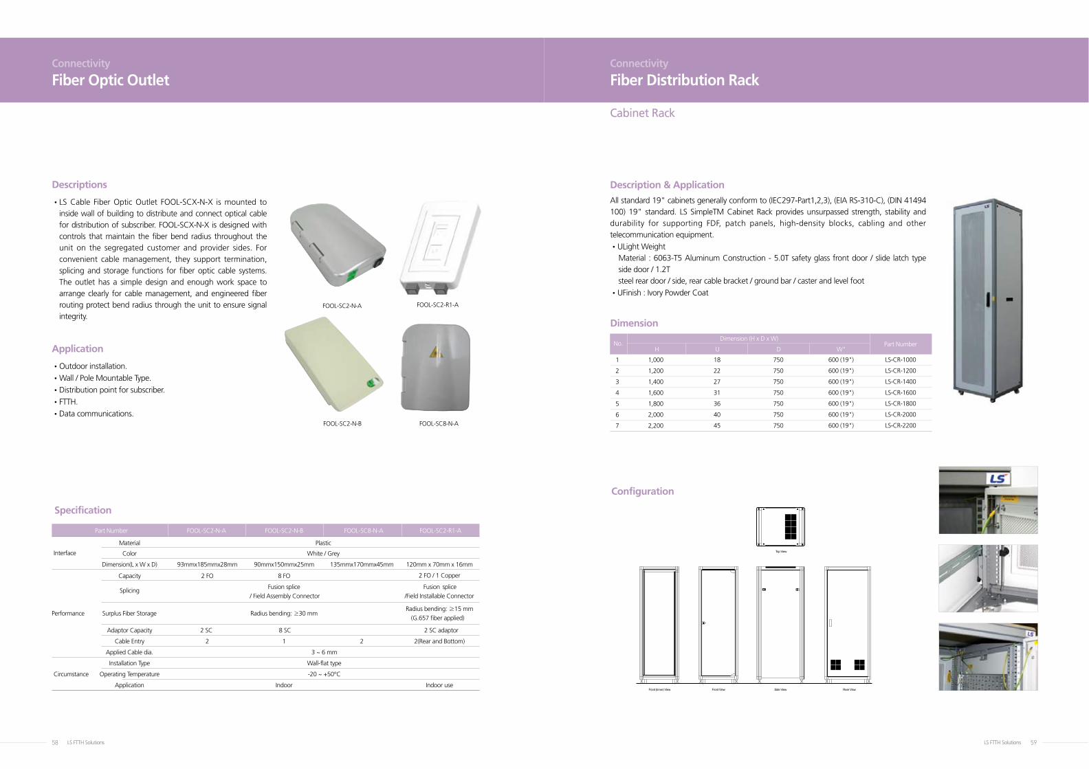
FOOL-SC2-N-A
FOOL-SC2-N-B FOOL-SC8-N-A
FOOL-SC2-R1-A
Connectivity
Fiber Optic Outlet
• LS Cable Fiber Optic Outlet FOOL-SCX-N-X is mounted to inside wall of building to distribute and connect optical cable for distribution of subscriber. FOOL-SCX-N-X is designed with controls that maintain the fiber bend radius throughout the unit on the segregated customer and provider sides. For convenient cable management, they support termination, splicing and storage functions for fiber optic cable systems. The outlet has a simple design and enough work space to arrange clearly for cable management, and engineered fiber routing protect bend radius through the unit to ensure signal integrity.
• Outdoor installation.
• Wall / Pole Mountable Type.
• Distribution point for subscriber.
• FTTH.
• Data communications.
Descriptions
Application
Part Number FOOL-SC2-N-A FOOL-SC2-N-B FOOL-SC8-N-A FOOL-SC2-R1-A
Material Plastic
Interface Color White / Grey
Dimension(L x W x D) 93mmx185mmx28mm 90mmx150mmx25mm 135mmx170mmx45mm 120mm x 70mm x 16mm
Capacity 2 FO 8 FO 2 FO / 1 Copper
Splicing
Fusion splice Fusion splice
/ Field Assembly Connector /Field Installable Connector
Performance Surplus Fiber Storage Radius bending: ≥30 mm Radius bending: ≥15 mm
(G.657 fiber applied)
Adaptor Capacity 2 SC 8 SC 2 SC adaptor
Cable Entry 2 1 2 2(Rear and Bottom)
Applied Cable dia. 3 ~ 6 mm
Installation Type Wall-flat type
Circumstance Operating Temperature -20 ~ +50°C
Application Indoor Indoor use
Specification
Connectivity
Fiber Distribution Rack
H U D W"
Description & Application
All standard 19" cabinets generally conform to (IEC297-Part1,2,3), (EIA RS-310-C), (DIN 41494 100) 19" standard. LS SimpleTM Cabinet Rack provides unsurpassed strength, stability and durability for supporting FDF, patch panels, high-density blocks, cabling and other telecommunication equipment.
•ULight Weight Material : 6063-T5 Aluminum Construction - 5.0T safety glass front door / slide latch type
side door / 1.2T steel rear door / side, rear cable bracket / ground bar / caster and level foot
•UFinish : Ivory Powder Coat
No.Dimension (H x D x W)
Part Number
Dimension
Front (Inner) View Front View Side View
Top View
Rear View
Configuration
1
2
3
4
5
6
7
1,000
1,200
1,400
1,600
1,800
2,000
2,200
18
22
27
31
36
40
45
750
750
750
750
750
750
750
600 (19")
600 (19")
600 (19")
600 (19")
600 (19")
600 (19")
600 (19")
LS-CR-1000
LS-CR-1200
LS-CR-1400
LS-CR-1600
LS-CR-1800
LS-CR-2000
LS-CR-2200
Cabinet Rack
LS FTTH Solutions60 LS FTTH Solutions 61
Connectivity
Fiber Distribution Rack
H U D W”
Description & ApplicationAll standard 19", 23" rack generally conform to (IEC297-Part1,2,3), (EIA RS-310-C), (DIN 41494 100) 19" standard. LS SimpleTM Open Rack provides unsurpassed strength, stability and durability for supporting FDF, patch panels, high-density blocks, cabling and other telecommunication equipment. Available various accessories.
•ULight weight Material : 6063-T5 Aluminum Construction. All 2 post vertical frames / 3.0T insulated plate /
ground bar / rear cable bracket
•UOptions Rack Support(Min. 600 ~ Max.1200 mm) Plinths (H200, 250, 300mm) Vertical Cable Management Cable Bracket and Panels
•UFinish : Black Powder Coat
No.
1
2
3
4
5
6
7
8
9
Description
Open Rack 19"
Open Rack 19"
Open Rack 19"
Open Rack 23"
Open Rack 23"
Open Rack 23"
Vertical Rack
Vertical Rack
Vertical Rack
1,800
2,000
2,200
1,800
2,000
2,200
1,800
2,000
2,200
36
40
46
36
40
46
-
-
-
360
360
360
360
360
360
160
160
160
600 (19")
600 (19")
600 (19")
700 (23")
700 (23")
700 (23")
150
150
150
LS-OR-19-1800
LS-OR-19-2000
LS-OR-19-2200
LS-OR-23-1800
LS-OR-23-2000
LS-OR-23-2200
LS-VR-1800
LS-VR-2000
LS-VR-2200
Dimension (H x D x W)Part Number
Dimensions
Configuration
W
200
100
A60635-T5 t=7.0
A60635-T5 t=4.0
A60635-T5 t=7.0
Open-Rack
H30
0
Open-Rack
Open Rack
19", 1U (2Hole, 4Hole) Improve Cable Routing
Front Filler Plate (1, 2, 3, 4, 5, 6U) Rear Cable BracketRear Cable Arrangement
19。。 Rack TypeFixed 110 Block, 25 & 50P and
Jumper Trough (1U)
19" Rack TypeFixed 110 Block, 100P
Jumper Trough (2U, 4U, 6U)
Surge Protector BRT19", 23" Rack Type
Ringrun Panel19", 23" Rack Type
Improve Cable Routing (1U, 2U)
19" Wire Cable Bracket19" Rack Type 1U
Improve Cable Routing
23" 110 Block Wire BracketFixed 110 Block 300P
(Leg Type)
Shelf19" Rack Type (D300mm)
Ground Bar (100mm)Grounding, Included Insulator
Cable DuctVertical Cable Routing
Rack SupporterOpen Rack Supporter
Min. 600 ~ Max. 1200 mm
PlinthOpen Rack Plinth
(H200, 250, 300 mm)
Power Strip15A, 110/220V
Rack Management
LS FTTH Solutions62 LS FTTH Solutions 63
EZ-SC(UPC/APC)
* Note 1) 3.5° Cleaving Modify
Connectivity
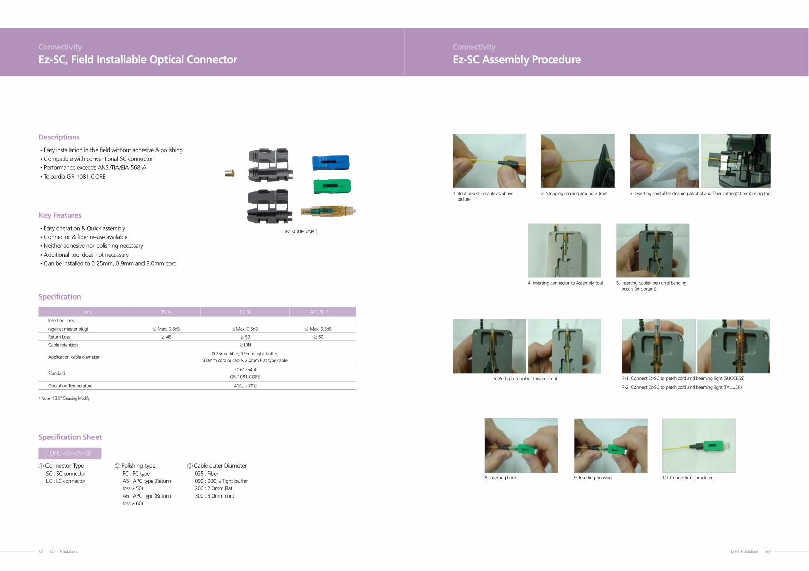
Ez-SC, Field Installable Optical Connector
•Easy installation in the field without adhesive & polishing
•Compatible with conventional SC connector
•Performance exceeds ANSI/TIA/EIA-568-A
•Telcordia GR-1081-CORE
• Easy operation & Quick assembly
•Connector & fiber re-use available
•Neither adhesive nor polishing necessary
•Additional tool does not necessary
•Can be installed to 0.25mm, 0.9mm and 3.0mm cord
Descriptions
Key Features
Specification Sheet
Specification
Item PCA PC 50 APC 60 NOTE 1)
Insertion Loss
(against master plug) ≤ Max. 0.5dB ≤Max. 0.5dB ≤ Max. 0.5dB
Return Loss ≥ 45 ≥ 50 ≥ 60
Cable retention ≥10N
Application cable diameter
0.25mm fiber, 0.9mm tight buffer,
3.0mm cord or cable, 2.0mm Flat type cable
Standard
IEC61754-4
GR-1081-CORE
Operation Temperature -40℃ ~ 70℃
① Connector TypeSC : SC connectorLC : LC connector
③ Cable outer Diameter025 : Fiber090 : 900㎛ Tight buffer200 : 2.0mm Flat300 : 3.0mm cord
② Polishing typePC : PC typeA5 : APC type (Return loss ≥ 50)A6 : APC type (Return loss ≥ 60)
FOFC-①-②-③
Connectivity
Ez-SC Assembly Procedure
6. Push push-holder toward front
1. Boot insert in cable as above picture
2. Stripping coating around 20mm 3. Inserting cord after cleaning alcohol and fiber cutting(10mm) using tool
4. Inserting connector to Assembly tool 5. Inserting cable(fiber) until bending occurs (important)
7-1. Connect Ez-SC to patch cord and beaming light (SUCCESS)
7-2. Connect Ez-SC to patch cord and beaming light (FAILUER)
8. Inserting boot 9. Inserting housing 10. Connection completed
LS FTTH Solutions64 LS FTTH Solutions 65
Connectivity
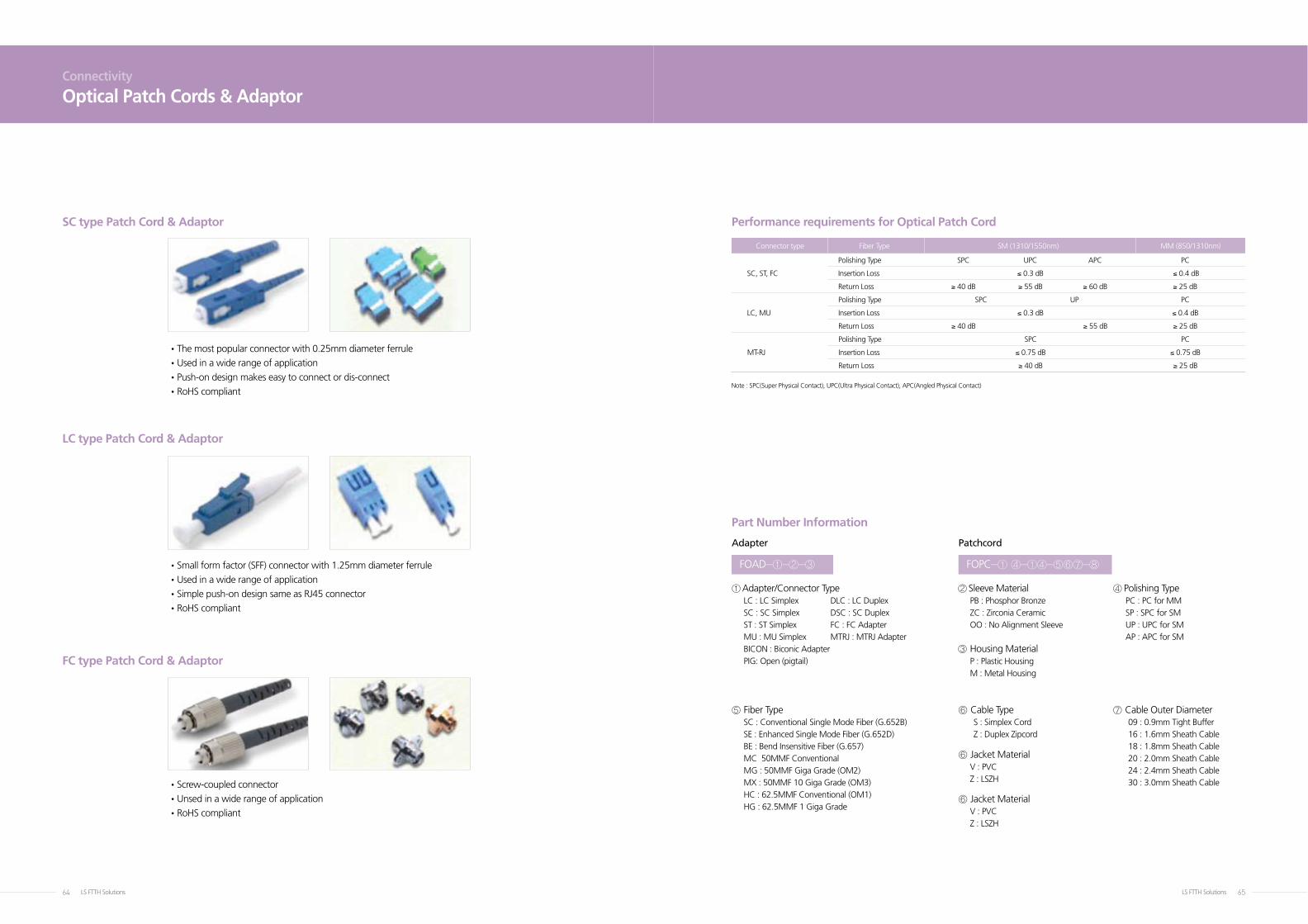
Optical Patch Cords & Adaptor
•The most popular connector with 0.25mm diameter ferrule
•Used in a wide range of application
•Push-on design makes easy to connect or dis-connect
•RoHS compliant
• Small form factor (SFF) connector with 1.25mm diameter ferrule
• Used in a wide range of application
• Simple push-on design same as RJ45 connector
• RoHS compliant
• Screw-coupled connector
•Unsed in a wide range of application
•RoHS compliant
SC type Patch Cord & Adaptor
LC type Patch Cord & Adaptor
FC type Patch Cord & Adaptor
Performance requirements for Optical Patch Cord
Part Number Information
Note : SPC(Super Physical Contact), UPC(Ultra Physical Contact), APC(Angled Physical Contact)
Connector type Fiber Type SM (1310/1550nm) MM (850/1310nm)
Polishing Type SPC UPC APC PC
SC, ST, FC Insertion Loss ≤ 0.3 dB ≤ 0.4 dB
Return Loss ≥ 40 dB ≥ 55 dB ≥ 60 dB ≥ 25 dB
Polishing Type SPC UP PC
LC, MU Insertion Loss ≤ 0.3 dB ≤ 0.4 dB
Return Loss ≥ 40 dB ≥ 55 dB ≥ 25 dB
Polishing Type SPC PC
MT-RJ Insertion Loss ≤ 0.75 dB ≤ 0.75 dB
Return Loss ≥ 40 dB ≥ 25 dB
① Adapter/Connector TypeLC : LC Simplex DLC : LC DuplexSC : SC Simplex DSC : SC DuplexST : ST Simplex FC : FC AdapterMU : MU Simplex MTRJ : MTRJ AdapterBICON : Biconic AdapterPIG: Open (pigtail)
⑤ Fiber TypeSC : Conventional Single Mode Fiber (G.652B)SE : Enhanced Single Mode Fiber (G.652D)BE : Bend Insensitive Fiber (G.657)MC 50MMF ConventionalMG : 50MMF Giga Grade (OM2)MX : 50MMF 10 Giga Grade (OM3)HC : 62.5MMF Conventional (OM1)HG : 62.5MMF 1 Giga Grade
③ Housing MaterialP : Plastic HousingM : Metal Housing
⑦ Cable Outer Diameter09 : 0.9mm Tight Buffer16 : 1.6mm Sheath Cable18 : 1.8mm Sheath Cable 20 : 2.0mm Sheath Cable24 : 2.4mm Sheath Cable 30 : 3.0mm Sheath Cable
⑥ Jacket Material V : PVCZ : LSZH
⑥ Cable Type S : Simplex CordZ : Duplex Zipcord
⑥ Jacket Material V : PVCZ : LSZH
② Sleeve Material PB : Phosphor Bronze ZC : Zirconia CeramicOO : No Alignment Sleeve
④ Polishing TypePC : PC for MMSP : SPC for SMUP : UPC for SMAP : APC for SM
FOAD-①-②-③ FOPC-① ④-①④-⑤⑥⑦-⑧
Adapter Patchcord
Telecommunication SystemOptical FiberOptical Fiber CableRF Feeder CableLAN CableFTTHHFC (Hybrid Fiber Coaxial Cable)
Power Transmission & Distribution SystemExtra High Voltage Cable SystemOverhead Transmission Line SystemOPGW I Busduct SystemOnshore & Offshore Cable SystemMedium & Low Voltage CableControl & Instrumentation Cable
Products & Systems of LS Cable


![Index [] · NEXT GENERATION NETWORK FTTx (FTTH - Fibre to the ... begins at the engineering project planning and design ... of fibre optic networks (FTTN and FTTH),](https://img.pdfslide.us/doc/110x75/5ad676357f8b9a5c638e5def/index-generation-network-fttx-ftth-fibre-to-the-begins-at-the-engineering.jpg)