Embed Size (px)
Citation preview

OFH3.pdf
Propagation of 10-Gb/s RZ data through a slow-light fiberdelay-line based on parametric process
Lilin Yi , Weisheng Hut, Yikai Sul, Lufeng Leng2, Jian Wu3, Xiangqin Tian', Guangtao Zhou3, Li Zhan'State Key Lab ofAdvanced Optical Communication Systems and Networks, Department ofElectronic Engineering
Shanghai Jiao Tong University, 800 DongChuan Rd, Shanghai 200240, China, s1giande; a]sity. edl. Cn2New York City college of Technology, City University ofNew York, NY 11202, USA
3Beying University ofPost and Telecommunications, Beijing 100876, China.
Abstract: We experimentally demonstrate fine-tuning of a slow-light delay line bypropagating 10-Gb/s RZ data packets through a parametric amplifier, and for the first timeinvestigate the system performance of such a delay line.©2006 Optical Society ofAmericaOCIS codes: (060.4370) Nonlinear optics, fibers; (190.4380) Nonlinear optics, four-wave mixing; (190.4970)Parametric oscillators and amplifiers.
1. IntroductionIn optical packet switching (OPS) networks, controlling the propagation velocity of the optical pulses in delay linesis important for buffering and synchronizing functions. Previous scheme employed electromagnetic inducedtransparency [1] in an ultracold atomic gas, which requires extreme conditions and is difficult to implement on aday-to-day basis. Recently, experiments have been carried out to delay the optical pulses utilizing semiconductors[2], as well as fiber nonlinearity, such as stimulated Brillouin scattering (SBS) [3,4], stimulated Raman scattering(SRS) [5] and Raman assisted fiber-optic parametric amplification (FOPA) [6]. These methods are suitable for roomtemperature operation and are relatively easy to realize and control. Particularly, the ones based on fibernonlinearity are compatible with fiber-optic communication systems. Among them, the SBS based scheme canachieve large delay but does not work at high data rates because of the very narrow bandwidth of SBS. The delaytime induced by the SRS method is very short owing to the wide bandwidth of the process. Raman assisted FOPAscheme can work at tens of Gb/s rate and has achieved delay of several bits. However, in [6] the signal wavelengthwas far from the pump wavelength and was therefore out of the 1.55pim telecommunication window. We furthernote that none of the proposed slow-light schemes has been evaluated at the system level by measuring the bit errorrate (BER) of delayed optical packets.
In this paper, we investigate, for the first time to the best of our knowledge, the system performance of delayed10-Gb/s return-to-zero (RZ) data packets in the 1.55pim telecommunication window. The time delay is achievedthrough the process of FOPA, and can be conveniently controlled by varying the parametric gain. We alsoinvestigate the pulse distortion due to saturated parametric gain to understand the limitation in our method. Ourexperiment verifies the feasibility of fine-tuning the time delay for 10-Gb/s packets, and indicates that higher-speeddata can be supported by the FOPA based slow-light delay line.
2. Experimental setupThe experimental setup is PC1 PC2 EDFA1 EDFA2 5 km DSF
shown in Fig.1. Two s9F2 VOA
tunable laser sources Rupler Isolator(TLSs) with a tuning , (1.28ns,10%)range from 1500 nm to ,PC PC51600 nm serve as the ThLSFOI0pump and the signal 1Gb/sdatasource, respectively. The atem
pump is sent to an eledTical tge PusPaem dock 1:4intensity modulator (IM) ----- ------'-gger--e- -t- B {- oouperdriven by an electrical 10G
Photodetecorpulse source with 1.28-nspulse width and lO0% duty Fig. 1. Experimental setupcycle. Polarization controllers (PC) are used to control the polarization state of the light. The modulated pump ispre-amplified by an erbium-doped fiber amplifier (EDFA) before being boosted by a second high-power EDFA witha maximal output power of 30 dBm. A tunable filter (TF) is inserted after EDFA2 for removing the strong
OFH3.pdf
amplification spontaneous emission (ASE) to effectively measure the gain spectrum of the FOPA. The signal isintensity-modulated by a 10-GHz clock to generate a RZ pulse train, and subsequently encoded by a 10-Gb/s NRZdata pattern. The pump and the signal are then combined through a 95/5 coupler and launched into a spool of 5-kmdispersion shifted fiber (DSF) to achieve amplification and delay. Note that the pump pulse and the signal patternmust be kept synchronous before entering the DSF, which is achieved by tuning the delay of the electrical pumppulse. The signal data packet is a fixed pattern "10111" followed by 123 '0'-bits so that all the "1" bits are alwayswithin the wide pump pulse. The waveforms of the pump and the signal pulses are shown as the insets in Fig. 1. Thezero dispersion wavelength of the DSF is -1558 nm and the dispersion slope is 0.08ps/(nm2.km). By tuning PC2and PC5, maximal signal gain can be obtained. After amplification and delay process in the DSF, the signal isseparated from the pump power by TF2. A variable optical attenuator (VOA) is used to control the amplified signalpower before measurement. We use an optical spectrum analyzer (OSA), an oscilloscope, and a bit error rate tester(BERT) to measure the optical spectra, signal waveforms, and BER, respectively.
3. The system design for slow-lightIn slow-light schemes, a narrowspectral resonance is needed to 0o 15601nm (a) °- (b)achieve significant amount of -10o 1560.5nm lamda -20' Pp + 23dB3m
-20- 35Bdelay. The spectral resonance -30 15626nm E -30- 415631nmm-induces a narrowband 40J 15641nm -40, 24.5dBm
gain/absorption peak in the B -50 1565mm -50-medium, which leads to a change 60 60AX
-70 --70-~~of the group velocity based on -80 -7...l80-Kramers-Kronig relationship [5]. 1545 1550 1555 1560 1565 1570 1575 1540 1550 1560 1570 1580* ~~~~~~~Wavelength (nm) Wavelength (nm)In the slow-light methods based
Fig.2 The measured ASE spectra with 0.2nm resolution. (a) The ASE spectraon stimulated scattering, the at 22dBm average pump power and variable pump wavelengths; (b) the ASEdelay time is proportional to the spectra at 1564.1nm pump wavelength and variable pump powers.gain and inversely proportionalto the gain bandwidth [4]. To achieve considerable time delay, high gain and narrow gain peak in the FOPA arenecessary. Firstly we measure the ASE spectra of the FOPA with a 22-dBm average pump power and at differentpump wavelengths, as depicted in Fig. 2 (a). When the pump wavelength is larger than the zero dispersionwavelength of the DSF, the parametric process produces two gain peaks, one on each side of the pump wavelength[7]. As the pump wavelength increases, the two gain peaks become narrower and closer to the pump wavelength,and the peak gain becomes higher. Signals falling into the narrow gain peak experience time delay. We chose1564.1nm as the pump wavelength because of the relatively narrow gain spectrum and the left gain peak beingclose to ITU-T CH 40 (1561.419nm). Then we show the ASE spectra at different pump powers in Fig. 2(b) toillustrate the impact of the pump power on the gain spectra. When the pump power exceeds 23dBm, the gainbandwidth is significantly broadened. To achieve good delay performance, it is necessary to balance between thegain value and the gain bandwidth.
40- 40-3531Pin=-13dBm 0 on-off gain: 37dB amplified signal , .
-* Pin=OdBm -15- filterd signal 30'
30 E inputsignal -25i25 -3020 ~~~~~~~~~~~~~~~~~~~~~~~~~~ ~~~~~~20-
5-45 15 155 lamda-p= 156411 nmCO 15- s 13lr(D ~~~ ~ ~~~~~~-0 jL* s=-3dB10 a60 CD Pp= 23dBm
C 1545 1550 1555 1560 1565 1570 1575 -5119 20 21 22 23 24 Wavn .n. 1558 1560 1562 1564 1566 1568
Pump power (dB) aelnth(m) Wavelength (nm)(a) (b) (c)
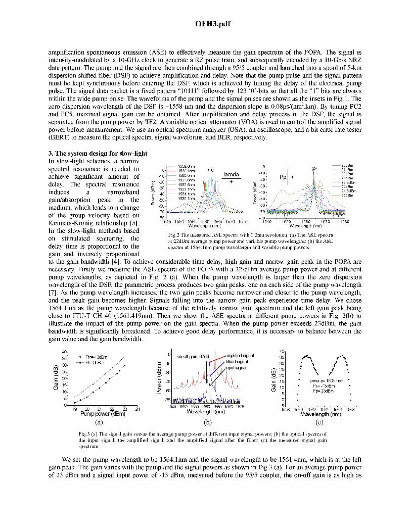
Fig.3 (a) The signal gain versus the average pump power at different input signal powers; (b) the optical spectra ofthe input signal, the amplified signal, and the amplified signal after the filter; (c) the measured signal gainspectrum.
We set the pump wavelength to be 1564.1m and the signal wavelength to be 1561.4nm, which is at the leftgain peak. The gain varies with the pump and the signal powers as shown in Fig.3 (a). For an average pump powerof 23 dBm and a signal input power of -13 dBm, measured before the 95/5 coupler, the on-off gain is as high as
OFH3.pdf
37dB. Higher signal power saturates the FOPA, leading to lower gain and therefore smaller delay. The opticalspectra of the input signal, the amplified signal and the filtered signal are shown in Fig. 3 (b), respectively. Since thesignal and pump wavelengths are close to the zero dispersion wavelength of the DSF, the four-wave mixing is verystrong, which produces high-order frequency components. With -13-dBm signal power and 23-dBm pump power at1564.lnm, the gain spectrum is shown in Fig.3 (c). In the parametric amplification process, the gain peak at theshorter wavelength corresponds to the slow light and the one at the longer wavelength leads to the fast light [6].Due to the lack of the longer wavelength filters, we only choose the wavelength lying in the left gain peak at1561.4nm and demonstrate the time delay.
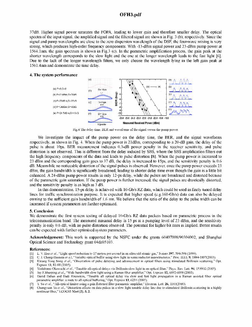
4. The system performance(a) (a) A A
1 X a(a) G (e) (b3(a) P=2,G=O dp
(b) P=21dBm,G=20dB .2 gt, (c)\1 t M' 0
(c) P=23dBm,G=37dB (c) D-15ps w . (d) AX~5p wt (d NNj%.XBv(d) P=24dBm,G=4OdB
___ (e)
(e) P=24.5dBm,G=4OdB (d) D-12ps -10
.. u ' X ~ao 4 *", 42 4r W1. 401 4"4
Measured Receied Power{dBm)I Ops/div
Fig.4 The delay time, BER and waveforms of the signal versus the pump power.
We investigate the impact of the pump power on the delay time, the BER, and the signal waveformsrespectively, as shown in Fig. 4. When the pump power is 21dBm, corresponding to a 20-dB gain, the delay of thepulse is about 10ps. BER measurement indicates 0.3-dB power penalty in the receiver sensitivity, and pulsedistortion is not observed. This is different from the delay induced by SBS, where the SBS amplification filters outthe high frequency components of the data and leads to pulse distortion [8]. When the pump power is increased to23 dBm and the corresponding gain goes to 37 dB, the delay is increased to 15ps, and the sensitivity penalty is 0.6dB. Meanwhile no noticeable distortion of the signal pulses is observed. However, once the pump power exceeds 23dBm, the gain bandwidth is significantly broadened, leading to shorter delay time even though the gain is a little bitenhanced. A 24-dBm pump power results in only 12-ps delay, while the pulses are broadened and distorted becauseof the parametric gain saturation. If the pump power is further increased, the signal pulses are drastically distorted,and the sensitivity penalty is as high as 3 dB.
In this demonstration, 15-ps delay is achieved with 10-Gb/s RZ data, which could be used in finely tuned delaylines for traffic synchronization purpose. It is expected that higher speed (e.g. 160-Gb/s) data can also be delayedowning to the sufficient gain bandwidth of 1.6 nm. We believe that the ratio of the delay to the pulse width can beincreased if system parameters are further optimized.
5. ConclusionWe demonstrate the first system testing of delayed 10-Gb/s RZ data packets based on parametric process in thetelecommunication band. The measured maximal delay is 15 ps at a pumping level of 23 dBm, and the sensitivitypenalty is only 0.6 dB, with no pulse distortion observed. The potential for higher bit rates is implied. Better resultscan be expected with further optimized system parameters.
Acknowledgement: This work is supported by the NSFC under the grants 60407008/90304002, and ShanghaiOptical Science and Technology grant 04dz05103.
References:[1] L. V. Hau et al., "Light speed reduction to 17 metres per second in an ultracold atomic gas," Nature 397, 594-598 (1999).[2] C. J. Chang-Hasnain et a.t, "Variable optical buffer using slow light in semiconductor nanostructures," Proc. IEEE 9, 1884-1897(2003).[3] Kwang Yong Song et al., "Observation of pulse delaying and advancement in optical fibers using stimulated Brillouin scattering," Opt.
Express 13, 82-88 (2005).[4] Yoshitomo Okawachi et al., "Tunable all-optical delays via Brillouin slow light in an optical fiber," Phy.s. Rev. Lett. 94, 153902 (2005).[5] Jay E.Sharping et al., "Wide bandwidth slow light using a Raman fiber amplifier," Opt. Express 12, 6092-6098 (2005).[6] David Dahan and Gadi Eisenstein, "Tunable all optical delay via slow and fast light propagation in a Raman assisted fiber optical
parametric amplifier: a route to all optical buffering," Opt. Express 13, 6234 (2005).[7] Y. Su et at., "All-optical limiter using a gain flattened fibre parametric amplifier," Electron. Lett. 26, 1103(2000).[8] Changyuan Yu et at., "Distortion effects on data pulses in a slow light tunable delay line due to stimulated Brillouin scattering in a highly
nonlinear fiber," ECOCO5 Mo4 121. 5. 2.


![Optimization of Adaptive MTI Filter · but also divided into single delay line canceller, double delay line canceller and multi-delay line canceller [4]. Single delay line canceller](https://img.pdfslide.us/doc/110x75/5eb5423662bfca09e766b7b9/optimization-of-adaptive-mti-filter-but-also-divided-into-single-delay-line-canceller.jpg)


![COMPARISONS OF IMPROVEMENTS ON TIME …delay line frequency characteristics [8]. Improvements on the transient transmission waveform and eye diagram of a serpentine delay line using](https://img.pdfslide.us/doc/110x75/5f2eba6afd652065a8780d2b/comparisons-of-improvements-on-time-delay-line-frequency-characteristics-8-improvements.jpg)