Embed Size (px)
Citation preview

ZHONG ET AL . VOL. XXX ’ NO. XX ’ 000–000 ’ XXXX
www.acsnano.org
A
CXXXX American Chemical Society
Fiber-Based Generator for WearableElectronics and Mobile MedicationJunwen Zhong,†,^ Yan Zhang,‡,§,^ Qize Zhong,†,^ Qiyi Hu,† Bin Hu,† Zhong Lin Wang,‡, ) and Jun Zhou†,*
†Wuhan National Laboratory for Optoelectronics and School of Optical and Electronic Information, Huazhong University of Science and Technology, Wuhan, 430074,China, ‡Beijing Institute of Nanoenergy and Nanosystems, Chinese Academy of Sciences, Beijing, China, §Institute of Theoretical Physics and Key Laboratory forMagnetism and Magnetic Materials of MOE, Lanzhou University, Lanzhou 730000, China, and )School of Materials Science and Engineering, Georgia Institute ofTechnology, Atlanta, Georgia 30332-0245, United States. ^J.-W. Zhong, Y. Zhang, and Q.-Z. Zhong contributed equally to this work.
Smart garments for monitoring physio-logical and biomechanical signals ofthe human body are key sensors for
personalized healthcare. However, they ty-pically require bulky battery packs or haveto be plugged into an electric plug in orderto operate. Thus, a smart shirt that canextract energy from human body motionsto run body-worn healthcare sensors isparticularly desirable. Here, we demon-strated a metal-free fiber-based generator(FBG) via a simple, cost-effective method byusing commodity cotton threads, a polyte-trafluoroethylene aqueous suspension, andcarbon nanotubes as source materials. TheFBGs can convert biomechanical motions/vibration energy into electricity utilizing theelectrostatic effect with an average outputpower density of ∼0.1 μW/cm2 and havebeen identified as an effective building ele-ment for a power shirt to trigger a wirelessbody temperature sensor system. Further-more, the FBG was demonstrated as a self-powered active sensor to quantitativelydetect human motion.Wearable electronics represents a para-
digm shift in consumer electronics for ap-plications such as integration with humanbody and health/wellness monitors, surgical
tools, and body sensor networks (BSN).1�4
The vision of noninvasive, automated perso-nalized healthcare using wearable wirelessmedical devices is a new and fast-growingmultidisciplinary research area.5 For exam-ple, continuous monitoring of humanblood pressure in patients with hyperten-sion can significantly increase medicationcompliance;6 real-time monitoring of elec-trocardiograph traces can be very effectiveat revealing early stages of heart diseases.7
Although sensing garments (with the com-mercial name of Smart shirt) for monitoringphysiological and biomechanical signals ofthe human body have already been in-vented for healthcare8 and sports training,9
they typically require bulky battery packs orhave to be plugged into an electric plug inorder to operate, which may limit the wide-spread usage of smart garments.10�13
Indeed, fueled by the rapid developmentof micro- and nanotechnologies, lowerpower consumption and even self-poweredsystems have profound impacts for biome-dical and portable electronics.14 Biomecha-nical energy represents a typical, universallyavailable, and feasible source of continuouspower for wearable devices. The humanbody is a surprisingly rich source of energy
* Address correspondence [email protected].
Received for review March 30, 2014and accepted April 26, 2014.
Published online10.1021/nn501732z
ABSTRACT Smart garments for monitoring physiological and biomechanical signals of the
human body are key sensors for personalized healthcare. However, they typically require bulky
battery packs or have to be plugged into an electric plug in order to operate. Thus, a smart shirt that
can extract energy from human body motions to run body-worn healthcare sensors is particularly
desirable. Here, we demonstrated a metal-free fiber-based generator (FBG) via a simple, cost-
effective method by using commodity cotton threads, a polytetrafluoroethylene aqueous suspension,
and carbon nanotubes as source materials. The FBGs can convert biomechanical motions/vibration
energy into electricity utilizing the electrostatic effect with an average output power density of
∼0.1 μW/cm2 and have been identified as an effective building element for a power shirt to trigger a
wireless body temperature sensor system. Furthermore, the FBG was demonstrated as a self-powered active sensor to quantitatively detect human motion.
KEYWORDS: electrostatic induction . fiber-based generator . mobile medication system
ARTIC
LE

ZHONG ET AL . VOL. XXX ’ NO. XX ’ 000–000 ’ XXXX
www.acsnano.org
B
including walking, arm swinging, finger motion, andbreathing. It is estimated that harvesting even 1�5%ofthe body's power without significantly increasing theload to the human body would be sufficient to runmany body-worn devices.15 Thus, devices that exploitbiomechanical motions as natural sources of energycan be particularly desirable. In the past two decades,researchers have developed multiple routes includ-ing electromagnetic fields,16,17 the piezoelectriceffect,18�27 the electrostatic effect,28,29 and the tribo-electric effect30�32 toward transforming biomechanicalmotion into electrical power.Ideally, if the energy harvesters were implemented
as textile-fiber structures, such fibers would provideperfect building elements for a smart shirt, as theycould be naturally integrated into fabrics during theweaving process without affecting comfort, flexibility,air permeability, and maneuverability. Qin et al. de-monstrated a nanogenerator based on the piezoelectriceffect using hybrid-structured microfiber-ZnO oxidenanowires,20 but its structure was very fragile and thepower outputwas so low that this kind of nanogeneratoris not feasible to be integrated into textiles for smartgarments.14 Here we introduce a cost-effective, metal-free, fiber-based generator that can convert biomecha-nical motions/vibration energy into electricity by theelectrostatic induction effect. The FBG consists of twoentangled modified-cotton threads: one is a carbonnanotube (CNT) coated cotton thread (CCT), and theother is a polytetrafluoroethylene (PTFE) and carbonnanotube coated cotton thread (PCCT). The FBGs canbe woven into a commercial textile to form a “powershirt” and used to trigger a wireless body temperature
monitor system.Moreover, the FBGswere demonstratedto quantitativelymonitor humanbodymotion. Thisworkestablishes the first proof-of-concept that the FBG canbe woven into fabrics and exploit the biomechanicalmotions as natural energy sources for wearable electro-nics and mobile medication applications.
RESULTS AND DISCUSSION
Fabrication of Fiber-Based Generators. The source mate-rials for the FBGs are commodity cotton threads, a PTFEaqueous suspension, and carbon nanotube ink. Thedetailed fabrication process is schematically shownin Figure 1a and supplementary methods. The cottonthreads were first treated by ethanol flame to eliminateredundant fibers (Supplementary Figure S1a and b)and treated by a nitric acid solution to increase thehydrophilicity. Thepretreated cotton threadswere thencoated with multiwalled carbon nanotubes by using ahomemade CNT ink via a “dipping and drying”methodto make them conductive (Figure 1a II).11 Comparedwith metal electrodes, CNTs have better adhesion withcelluloses due to their mutual strong chemical bonds.33
Moreover, compared with the thermal evaporationmethod, which is normally utilized to deposit metalelectrodes, “dipping and drying” is a simple and cost-effective method. Scanning electron microscopy (SEM)images shown in Figure 1b and c reveal that the surfaceof the cotton thread with a diameter of ∼240 μm wasfully covered by CNTs, with a mass loading densityof ∼0.207 mg/cm. The final CCTs have a good flexibi-lity and conductivity with a constant resistance of∼0.644 kΩ/cm in both straight and curving condition(Supplementary Figure S2a). The maximum tensile
Figure 1. Fabrication offiber-basedgenerator (FBG). (a) Schematic diagram illustrating the fabricatingprocess of an FBG. SEMimages of a carbon nanotube coated cotton thread (CCT) with (b) low and (c) highmagnification, respectively. SEM images ofpolytetrafluoroethylene (PTFE) and carbon nanotube coated cotton thread (PCCT) with (d) low and (e) high magnification,respectively. Digital photography of FBGs (f) with linear shape, (g) with curved shape, and (h) woven into fabric.
ARTIC
LE
ZHONG ET AL . VOL. XXX ’ NO. XX ’ 000–000 ’ XXXX
www.acsnano.org
C
stress that can be borne by the CCT and FBG is∼180 and ∼210 MPa, respectively (SupplementaryFigure S2b).
PCCTs were prepared by coating CCTs with PTFE viaa “dipping and drying”method (Figure 1a III) followedby a sequence annealing process to enhance theadhesion. As one of the representative electret materi-als for power generators,29 PTEF can theoreticallyretain electrostatic charges on its surfaces for overtens of years.34 The top view and cross-sectional viewSEM images shown in Figure 1d and Figure S1d reveala core�shell-structured character with a diameter of∼500 μm. There are some minor cracks on the surfaceof the PCCTs, which may be due to the stress-releasingprocess. The formation of the cracks can enhance theflexibility of the PCCTs. A high-resolution SEM imageshown in Figure 1e indicates that the PTFE layer wascomposed of oval-like nanoparticles with diameters ofless than 200 nm. The PCCTs were polarized via oxygenplasma treatment and resulted in net negative electro-static charges (Q) on the PTFE surface, and 40 minof polarization can dramatically increase the surfacepotential of PCCTs from ca. �9 V for fresh samples toca. �660 V (Supplementary Figure S3a). The surfacepotential decreased to∼470 V in 30 h and could almostmaintain this value for more than 20 days. The highstability of the surface potential in PCCTs is beneficialfor long-term sustainable applications of the device.Finally, a CCT and a PCCT were entangled with eachother to form a lightweight, flexible FBG with double-helix structure (Figure 1a IV, Figure 1f and g). The helixturns and leaving gaps of the FBG can be adjusted,and the two ends of the FBG were fixed by commodity
cotton threads. In our study, the FBGs can be easilywoven into fabric to form a “power shirt” (Figure 1h).
Proposed Power Generation Mechanism of the Fiber-Based Generators. Although the FBG has a complex“double-helix” structure, the FBG can be approximatelyregarded as numerous parallel-wire capacitors con-nected in parallel by ignoring the edge effect. In asimplifiedmodel, the equivalent circuit of the FBGwithan external load of R is illustrated in Figure 2a. In theoriginal state (Figure 2a, I), the PTFE surface, the outerlayer of the PCCT, was charged with negative electro-static charges of Q while the CCT was grounded,and the CNT layers in both the PCCT and CCT wouldproduce positive charges of Q1 and Q2, respectively,due to the electrostatic induction and conservationof charges, where Q = �(Q1 þ Q2).
32 Therefore, thecharges Q on PTFE could be considered as an electricfield source.
When the FBG was stretched (Figure 2a, II), ashrinkage of the interfiber gap distance d betweenCCT and PCCT would result in more induced positivecharges accumulating in the CNT layer of the CCTbecause of the electrostatic induction. Accordingly,free electrons of CCT would flow to the CNT layerof PCCT in order to balance the field from Q. Thus, thisprocess produces an instantaneous positive current(Figure 2b) (we defined a forward connection formeasurement as a configuration with the positiveend of the electrometer connected to the CNT elec-trode of the PCCT). It is necessary to note that thecharge Q on PTFE will not be annihilated even whenit contacts with the CNT-coated fiber, because theelectrostatic charges are naturally impregnated into
Figure 2. Power generation mechanism of the FBG. (a) Schematic diagram illustrating the power generation mechanismof the FBGwith an external load of Rwhen the device is at (I) the original, (II) stretching, and (III) releasing states, respectively.The corresponding output current�time curves (d) when forward-connected to the measurement system and (c) whenreverse-connected to the measurement system.
ARTIC
LE

ZHONG ET AL . VOL. XXX ’ NO. XX ’ 000–000 ’ XXXX
www.acsnano.org
D
the insulator PTFE. In the reverse case, when the FBGwas released (Figure 2a III), the device would recoverback to its original shape and the internal gap d isincreased, resulting in an increase ofQ1 and a decreaseof Q2; thus, an instantaneous negative current couldbe produced (Figure 2b). Therefore, a stretching�releasing process of the FBG will generate an alternat-ing current (ac) through the load.
As the electrostatic charges remain stable (Sup-plementary Figure S3b) for a relative long time onthe PCCT surface, the FBG can be thought of as a typeof variable-capacitance generator. Switching polaritytests were also carried out to confirm that the mea-sured output signals were generated from the FBGrather than from the measurement system (Figure 2c).
Power Generation Performance of a Single Fiber-BasedGenerator. The typical power generation performanceof the FBG with a length of ∼9.0 cm and eighthelix turns was systematically studied by periodicallystretching and releasing the FBG with controlledfrequencies and strains. The measuring system is sche-matically shown in Figure S4; one end of the FBGwas fixed on an x-y-z 3D mechanical stage that wasmounted tightly on an optical table, while the otherend was fixed on a vibration source with controlledfrequency. The output current through an externalload of 80 MΩ was continuously monitored.
Figure 3a shows the output current of an FBG withan applied strain of 0, 0.54%, 1.08%, 1.61%, and 2.15%
at a given frequency of 5 Hz. No current signal wasdetected when there was no stimulation applied onthe FBG. Generally, an increase of strain increased thepeak output current, from 3.98 nA at 0.54% to 11.22 nAat 2.15% (Figure S5b). The integration of each currentpeak can give the total charges transferred betweenthe electrodes, as shown in Figure 3b and Figure S5c,indicating that the total amount of charges transferredincreased with the increase of strain, which is consis-tent with our model discussed above. The outputcurrent of an FBG varied with stimulation frequenciesof 1.3, 2, 3, 4, and 5 Hz for a given strain of 2.15% isshown in Figure 3c, revealing a clear increasing trendwith the increase of frequency. The integrations ofeach current peak from each of the five differentstimulation frequencies are shown in Figure 3d andFigure S5d, indicating that the total amount of thecharges transferred almost stays constant at ∼0.16 nCat a given strain of 2.15%. This study indicates that thepeak output current is related to both the stimulationfrequency and magnitude of strain, while the amountof the transferred charges is related only to the appliedstrain.
The characterization curve of the dependence ofthe output power on the external load is shown inFigure S6a. It was measured at a given frequency (5 Hz)and degree of deformation (2.15% strain). The instan-taneous output peak power value is 11.08 nW, corre-sponding to an optimal external load of 100 MΩ.
Figure 3. Power generationperformance of a single FBG thoughan external loadof 80MΩunder different testing conditions.(a) Output current�time curve and (b) the corresponding total charge transfer of a FBG varied with stimulation strains of 0,0.54%, 1.08%, 1.61%, and 2.15% for a given frequency of 5 Hz. (c) Output current�time curve and (d) the corresponding totalcharge transfer of a FBG varied with stimulate frequencies of 1.3, 2, 3, 4, and 5 Hz for a given strain of 2.15%. (f) Five hours(∼90 000 cycles) continuous power generation of the FBG and (g) the variation of peak output current over time.
ARTIC
LE
ZHONG ET AL . VOL. XXX ’ NO. XX ’ 000–000 ’ XXXX
www.acsnano.org
E
To rule out the possible artifacts, the measurementof the output current was carried out when two FBGswere connected in parallel with an external load of80 MΩ under the same frequency and deformationcontrol. As shown in Figure S6b, the total outputcurrent was enhanced, indicating that the electricityoutput of the FBGs satisfied a linear superpositioncriterion in the basic circuit connections.
The stability of the FBG is anessential factor to ensureits practical applications. In our study, the FBG wascontinuously operated for 90 000 cycles at a stimulationstrain of 2.15% and frequency of 5 Hz. Typical data in1 min for every hour are shown in Figure 3e, and onlya small variation of peak output current is seen inFigure 3f, indicating the highly stable power genera-tion of the FBG. This feature may be attributed tothe robustness of the device, as no noticeable surfacemorphology degradation of the PCCT and CCT after thetest was proven from the SEM analysis (Figure S7).
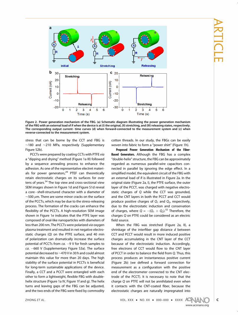
Fiber-Based Generator as an Active Sensor for Body MotionDetection. A single FBG was fixed on a subject's indexfinger. We checked the output current flowing throughan external load of 80 MΩ at five different bend-ing�releasing motion states that were labeled as stateI, II, III, IV, and V, respectively (insets in Figure 4a). In eachmotion state, the finger was bent to the same ampli-tude and then released for three cycles. It can be seenthat a couple of output current signals with oppositepolaritywould begenerated in every bending�releasingmotion cycle (Figure 4a). The instantaneousoutputpowergenerated by the FBG with small-scale finger motioncould reach ∼0.91 μW (average area power densityof ∼0.1 μW/cm2, Supplementary Note 1), which was
enough to power an electronic device such as a liquidcrystalline display (LCD) with small power consumption(Supplementary Video 1 and Figure S8). As discussedabove, the peak output currents were decided by bothmotion speed and motion amplitude. However, in ourexperiments, the finger motion speed was manuallycontrolled; thus, a small fluctuation is possible (FigureS9a). As the total charge transfer corresponds only tothe motion amplitude regardless of the motion speed,we have integrated each positive current peak for fivedifferent motion states, as shown in Figure S9b andFigure 4b, indicating that the total amount of chargestransferred increased with the increase of motion am-plitude, from which the motion states were quantita-tively identified. This behavior indicates that the FBGcan be used as a self-powered active sensor28,35�37
for detecting tiny muscle motion/stretching withoutan external power at least for the sensor unit and haspotential applications in patients' rehabilitation trainingand sports training.
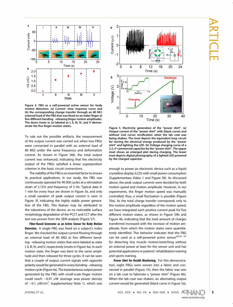
Power Shirt for Health Monitoring. For this demonstra-tion, eight FBGs were woven into a fabric and con-nected in parallel (Figure 1h), then the fabric was sewon a lab coat to fabricate a “power shirt” (Figure 6b).When the lab coat was shaken, an alternating outputcurrent would be generated (black curve in Figure 5a).
Figure 4. FBG as a self-powered active sensor for bodymotion detection. (a) Current�time response curve and(b) the corresponding change transfer through an 80 MΩexternal load of the FBG that was fixed on an index finger atfive different bending�releasing fingermotion amplitudes.The down insets in (a) labeled as I, II, III, IV, and V demon-strate the five finger-motion states.
Figure 5. Electricity generation of the “power shirt”. (a)Output current of the “power shirt” with (black curve) andwithout (red curve) rectification when the lab coat wasbeing shaken. The inset depicts the equivalent loop circuitfor storing the electrical energy produced by the “powershirt” and lighting the LED. (b) Voltage charging curve of a2.2 μF commercial capacitor by the “power shirt”. The upperinset shows an enlarged plot during charging. The lowerinset depicts digital photography of a lighted LED poweredby the charged capacitor.
ARTIC
LE

ZHONG ET AL . VOL. XXX ’ NO. XX ’ 000–000 ’ XXXX
www.acsnano.org
F
Additionally, an approach to prove the electricitygenerated by FBGs has also been implemented. Asillustrated in Figure S10, when shaking only the elec-trodes that were fixed on the lab coat, there were nosignals detected by the measuring instrument. Theoutput electric signals were first rectified by a bridgerectifier (inset in Figure 5a), transforming alternatingcurrent to direct current (red curve in Figure 5a) andcharging the capacitor continuously (SupplementaryVideos 2). The charging curve of the 2.2 μF commercialcapacitor is shown in Figure 5b. The capacitor couldbe charged to 2.4 V in around 27 s, and every step ofvoltage increase corresponded to each vibration ofthe lab coat (upper-left inset in Figure 5b). After thecapacitor was fully charged, it could light up a red lightemitting diode (LED), as shown in the lower-right insetof Figure 5b, indicating that the electricity generatedby the “power shirt” can be stored in a storage cell andpower commercial electronics.
Furthermore, the “power shirt” had successfullytriggered a homemade wireless body temperaturemonitoring system. The working principle of thewireless body temperature monitor system is sche-matically shown in Figure 6a and Figure S11. The“power shirt” was used to charge a 10 nF capacitor;when the voltage of the capacitor reached a thresh-old of 2.4 V, it would wake up a microcontroller unit(MCU, Atmega168 V-10PI, with a power consump-tion of 0.18 μW in standby mode and 27 μW inactive mode) that was driven by an external powersource. TheMCU issued instructions to the thermistorintegrated into the wristband to detect surround-ing temperature and converted the detected tem-perature analog signals into digital signals by an
analog�digital (AD) module. Then, the digital signalswere loaded directly into a square wave generatedby the MCU in which the half-period of the waveindicated the temperature value andwas transmittedby an infrared diode. Finally, the receiver infrareddiode simultaneously captured the signals that weredemodulated by another MCU and identified thetemperature value, and sent the information to thedisplay screen.
In our study, the active body temperature monitorsystem detected the surrounding temperature wherethe wristband was worn when shaking the lab coat(Supplementary Videos 3). The modulated signalsshown in Figure 6c and e represent the detected temp-eratures when the wristband was placed on a deskor on the human wrist, respectively. Meanwhile, thecorresponding temperature values of 22 �C for roomtemperature and 37 �C for body temperature areshown in the display (Figure 6d and f).
CONCLUSIONS
In summary, we have fabricated a flexible andmetal-free FBG via a cost-effective method by using com-modity cotton threads, a PTFE aqueous suspension,and carbon nanotubes as source materials. The FBGcan convert biomechanical motions/vibration energyinto electricity utilizing the electrostatic effect with anaverage output power density of ∼0.1 μW/cm2. TheFBGwas demonstrated as a self-powered active sensorto quantitatively detect human motion. Furthermore,FBGs had been identified as an effective buildingelement for a power shirt that could trigger a wirelesshomemade body temperature sensor system. Thiswork establishes the first proof-of-concept that FBGs
Figure 6. Wireless body temperature sensor system triggered by the “power shirt”. (a) Schematic diagram and (b) digitalphotography of a wireless body temperature monitor system triggered by the power clothes. Modulated and demodulatedsignals that represent the temperatures detectedby the sensorwhen thewristbandwasplaced (c) on adesk or (e) on a humanwrist. The corresponding temperature values of (d) 22 �C for room temperature and (f) 37 �C for body temperature are shownin the display screen.
ARTIC
LE

ZHONG ET AL . VOL. XXX ’ NO. XX ’ 000–000 ’ XXXX
www.acsnano.org
G
can be woven into textiles and extract energy frombiomechanical motions for powering mobile medical
systems, making the self-powered smart garmentpossible.
EXPERIMENTAL SECTIONFabrication of CNT Ink. First, CNTs were treated with 5 M nitric
acid for 30 min to increase the hydrophilicity. Then 20 mg/mLacid pretreated CNTs and 40 mg/mL sodium dodecyl benzene-sulfonate (SDBS) were dispersed in deionized water. Last, themixturewas sonicated for 20min using an ultrasonic cell disruptor(Kesheng Sonics Vibra Cell, 550 F).
Fabrication of CCT. Since the surface of the commercial cottonthreads was fibrous, the cotton threads were first treated withan ethanol flame to eliminate redundant fibers. Then they werecleaned by acetone, ethanol, and deionizedwater several times,following by immersing into 5 M nitric acid solution for 1 h toincrease the hydrophilicity. The cotton threads were coatedby CNTs by using the CNT ink mentioned above through the“dipping and drying”method.38 Specifically, the treated cottonthreads were alternately dipped into the CNT ink and dried at80 �C in an oven. After this process was repeated several times,the conductive cotton threads kept dry at 80 �C in an oven for 2 h.
Fabrication of PTFE and PCCT. The PCCT was fabricated throughthe “dipping and drying” method as well. Typically, the CCTwas immersed into PTFE solution (Aladdin, 60%wt, aqueous) for30 s and then dried at 60 �C for 5 min. The “dipping and drying”process was repeated three times to ensure that the CCTwas completely coated by PTFE. The resulting PCCT was thenannealed at 150 �C in an oven for 12 h. Finally, the PCCTs werepolarized via the plasma method with a service power of 120 Wfor 40 min.
Assembly of FBG and the “Power Shirt”. A CCT and a PCCT wereentangled with each other to form a double-helix-structuredevice. The helix turns and leaving gaps of the FBG can beadjusted, and the two ends of the FBGwere fixed by commoditycotton threads. Then the FBGs were woven into the fabric toform a “power shirt”.
Characterization. Themorphology of the samples was probedby a high-resolution field emission scanning electron micro-scope (FEI Nova NanoSEM 450). The conductance of the CCTwas studied by a Keithley 2400 source meter. The mechanicalproperty of the CCTwas characterized by an electronic universalmaterial testing machine (RGM-4005T, Reger, China). The plas-ma polarization method was carried out with a PDC-MG gasplasma dry cleaner (Hengming, China). The surface potential ofPTFE was detected by an electrometer (EST102, Huajing Beijing,China). The periodic stretching�releasing process of the FBGwas stimulated by a resonator (JZK, Sinocera, China), which wascontrolled by a swept signal generator (YE 1311-D, Sinocera,China). The power generation performance measurement sys-temof the FBG is schematically shown in Figure S4, in which oneend of the FBG was fixed on an x-y-zmechanical stage that wasmounted tightly on an optical table, while the other end wasfixed on the resonator. During the measurement process, asingle FBG was periodically stretched and released with differ-ent degrees of strain and frequency by the resonator (JZK).Simultaneously, the current signals through an external load of80 MΩ were measured by a Stanford low-noise current pre-amplifier (model SR570). The modulated and demodulatedsignals generated by the wireless body temperature sensorsystem were monitored by an Agilent DSOX-2014 oscilloscope.
Conflict of Interest: The authors declare no competingfinancial interest.
Acknowledgment. This work was financially supported bythe National Natural Science Foundation of China (51322210,51002056), a Foundation for the Author of National ExcellentDoctoral Dissertation of PR China (201035), the FundamentalResearch Funds for the Central Universities (HUST: 2012YQ025,2013YQ049, 2013TS160), and the seed project ofWuhanNationalLaboratory for Optoelectronics. The authors would like to thankProf. J. Tang and Dr. F. R. Fan for their constructive suggestions.
Supporting Information Available:More detailed informationabout calculations, sensor working principle, I�V curve ofCCT, surface potential of PTFE, supporting movies 1�3, etc.This material is available free of charge via the Internet athttp://pubs.acs.org.
REFERENCES AND NOTES1. Rogers, J. A. Electronics: A Diverse Printed Future. Nature
2010, 468, 177–178.2. Yamada, T.; Hayamizu, Y.; Yamamoto, Y.; Izadi-Najafabadi,
A.; Futaba, D. N.; Hata, K. A Stretchable Carbon NanotubeStrain Sensor for Human-Motion Detection. Nat. Nano-technol. 2011, 6, 296–301.
3. Wang, C.; Hwang, D.; Yu, Z.; Takei, K.; Park, J.; Chen, T.; Ma,B.; Javey, A. User-Interactive Electronic Skin for Instanta-neous Pressure Visualization. Nat. Mater. 2013, 12, 899–904.
4. Lipomi, D. J.; Vosgueritchian, M.; Tee, B.; Hellstrom, S. L.;Lee, J. A.; Fox, C. H.; Bao, Z. Skin-Like Sensors of Pressureand Strain Enabled by Transparent, Elastic Films of CarbonNanotubes. Nat. Nanotechnol. 2011, 6, 788–792.
5. Ross, P. Managing Care through the Air. IEEE Spectrum2004, 6, 26–31.
6. Flowerday, A.; Smith, R. Lessons Learnt from Long-TermChronic Condition Monitoring. Proc. 1st Int. WorkshopWearable Implantable Body Sensor Network 2004, 48.
7. Needham, P.; Gamlyn, L. Arrhythmia Analysis in the Com-munity. Proc. 1st Int. WorkshopWearable Implantable BodySensor Network 2004, 49–50.
8. Wolffenbuttel, M. R.; Regtien, P. P. L. Polysilicon Bridges forthe Tealization of Tactile Sensors. Sens. Actuators, A 1991,26, 257–264.
9. Chu, Z.; Sarrob, P. M.; Middelhoeka, S. Silicon Three-AxialTactile Sensor. Sens. Actuators, A 1996, 54, 505–510.
10. Jost, K.; Stenger, D.; Perez, C. R.; McDonough, J. K.; Lian, K.;Gohotsi, Y.; Dion, G. Knitted and Screen Prited Carbon-Fiber Supercapacitors for Applications in Wearable Elec-tronics. Energy Environ. Sci. 2013, 6, 2698–2705.
11. Hu, L.; Pasta, M.; Mantia, F. L.; Cui, L.; Jeong, S.; Deshazer,H. D.; Choi, J.; Han, S.; Cui, Y. Porous, and ConductiveEnergy Textiles. Nano Lett. 2010, 10, 708–714.
12. Lee, Y.; Kim, J.; Lee, J.; Kim, H.; Choi, S.; Seo, J.; Jeon, S.; Kim,T.; Lee, J.; Choi, J. Wearable Textile Battery Rechargeable bySolar Energy. Nano Lett. 2013, 13, 5753–5761.
13. Chen, T.; Qiu, L.; Yang, Z.; Cai, Z.; Ren, J.; Li, H.; Lin, H.; Sun, X.;Peng, H. An Integrated Energy Wire for Both PhotoelectricConversion and Storage. Angew. Chem., Int. Ed. 2012, 51,11977–11980.
14. Qi, Y.; McAlpine, M. C. Nanotechnology-Enabled Flexibleand Biocompatible Energy Harvesting. Energy Environ. Sci.2010, 3, 1275–1285.
15. Starner, T. Human-Powered Wearable Computing. IBMSyst. J. 1996, 35, 618–629.
16. Rome, L. C.; Flynn, L.; Goldman, E. M.; Yoo, T. D. GeneratingElectricity While Walking with Loads. Science 2005, 309,1725–1728.
17. Donelan, J. M.; Li, Q.; Naing, V.; Hoffer, J. A.; Weber, D. J.;Kuo, A. D. Biomechanical Energy Harvesting: GeneratingElectricity duringWalkingwithMinimal User Effort. Science2008, 319, 807–810.
18. Nelson, L.; Bowen, C.; Stevens, R.; Cain, M.; Stewart, M.Modelling and Measurement of Piezoelectric Fibers andInterdigitated Electrodes for the Optimisation of PiezofiberComposites. SPIE Conf. Proc. 2003, 5053, 556–567.
19. Wang, Z. L.; Song, J. Piezoelectric Nanogenerators Basedon Zinc Oxide Nanowire Arrays. Science 2006, 312, 242–246.
ARTIC
LE
ZHONG ET AL . VOL. XXX ’ NO. XX ’ 000–000 ’ XXXX
www.acsnano.org
H
20. Qin, Y.; Wang, X.; Wang, Z. L. Microfibre-Nanowire HybridStructure for Energy Scavenging. Nature 2008, 451, 809–813.
21. Qin, Y.; Jafferis, N. T.; Lyons, K.; Christine, J.; Lee, M.; Ahmad,H.; McAlpine, M. C. Piezoelectric Ribbons Printed ontoRubber for Flexible Energy Conversion. Nano Lett. 2010,10, 524–528.
22. Park, K.; Lee, M.; Liu, Y.; Moon, S.; Hwang, G.; Zhu, G.; Kim, J.;Kim, S.; Kim, D.; Wang, Z. L.; et al. Flexible NanocompositeGenerator Made of BaTiO3 Nanoparticles and GraphiticCarbons. Adv. Mater. 2012, 24, 2999–3004.
23. Lee, K.; Kumar, B.; Seo, J.; Kim, K.; Sohn, J.; Cha, S.; Choi, D.;Wang, Z. L.; Kim, S. P-Type Polymer-Hybridized High-Performance Piezoelectric Nanogenerators. Nano Lett.2012, 12, 1959–1964.
24. Chang, C.; Tran, V. H.; Wang, J.; Fuh, Y. K.; Lin, L. Direct-WritePiezoelectric Polymeric Nanogenerator with High EnergyConversion Efficiency. Nano Lett. 2010, 10, 726–731.
25. Persano, L.; Dagdeviren, C.; Su, Y.; Zhang, Y.; Girarod, S.;Pisignano, D.; Huang, Y.; Rogers, J. A. High PerformancePiezoelectric Devices Based on Aligned Arrays of Nano-fibers of Poly(vinylidenefluoride-co-trifluoroethylene). Nat.Commun. 2012, 4, 1633.
26. Lee, B.; Zhang, J.; Zueger, C.; Chung, W.; Yoo, S. Y.; Wang, E.;Meyer, J.; Ramesh, R.; Lee, S. Virus-Based PiezoelectricEnergy Generation. Nat. Nanotechnol. 2012, 7, 351–356.
27. Sun, C.; Shi, J.; Bayerl, D. J.; Wang, X. PVDF Microbelts forHarvesting Energy from Respiration. Energy Environ. Sci.2011, 4, 4508–4512.
28. Zhong, Q. Z.; Zhong, J.W.; Hu, B.; Hu, Q.; Zhou, J.;Wang, Z. L.Paper-Based Nanogenerator As Power Source and ActiveSensor. Energy Environ. Sci. 2013, 6, 1779–1784.
29. Boland, J.; Chao, Y.; Suzuki, Y.; Tai, Y. C. Micro Electret PowerGenerator. Proc. 16th IEEE Int. Conf. MEMS 2003, 538–541.
30. Fan, F.; Tian, Z.; Wang, Z. L. Flexible Triboelectric Generator.Nano Energy 2012, 1, 328–334.
31. Zhang, X.; Han,M.;Wang, R.; Zhu, F.; Li, Z.; Wang,W.; Zhang,H. Frequency-Multiplication High-Output TriboelectricNanogenerator for Sustainably Powering BiomedicalMicrosystems. Nano Lett. 2013, 13, 1168–1172.
32. Post, E. R.; Waal, K. Electrostatic Power Harvesting inTextiles. Proc. ESA Ann. Meet. Electrost. 2010, Paper G1.
33. Hu, L.; Choi, J.; Yang, Y.; Jeong, S.; Mantia, F. L.; Cui, L.; Cui,Y. P. Highly Conductive Paper for Energy-Storage Devices.Natl. Acad. Sci. U.S.A. 2009, 106, 21490–21494.
34. Malecki, J. A. Linear Decay of Charge in Electrets. Phys. Rev.B 1999, 59, 9954–9960.
35. Lee, S.; Hinchet, R.; Lee, Y.; Yang, Y.; Lin, Z.; Ardila, G.;Montes, L.; Mouis, M.; Wang, Z. L. Ultrathin Nanogenera-tors as Self-Powered/Active Skin Sensors for Tracking EyeBall Motion. Adv. Funct. Mater. 2013, 24, 1163–1168.
36. Hu, Y.; Yang, J.; Jing, Q.; Niu, S.; Wu, W.; Wang, Z. L. Tribo-electric Nanogenerator Built on Suspended 3D SpiralStructure as Vibration and Positioning Sensor and WaveEnergy Harvester. ACS Nano 2013, 7, 10424–10432.
37. Lin, L.; Xie, Y.; Wang, S.; Wu, W.; Niu, S.; Wen, X.; Wang, Z. L.Triboelectric Active Sensor Array for Self-Powered Staticand Dynamic Pressure Detection and Tactile Imaging.ACS Nano 2013, 7, 8266–8274.
38. Liu, N. S.; Ma, W. Z.; Tao, J. Y.; Zhang, X. H.; Su, J.; Li, L. Y.;Yang, C. X.; Gao, Y. H.; Golberg, D.; Bando, Y. Cable-TypeSupercapacitors of Three-Dimensional Cotton ThreadBased Multi-Grade Nanostructures for Wearable EnergyStorage. Adv. Mater. 2013, 25, 4925–4931.
ARTIC
LE