Embed Size (px)
Citation preview
PC20l @ar,d and Software
-zaFiFeoFi-oz
=zeF
Campbell Scientific, Inc

PC2O1 CARD & SOFTWAREINSTRUCTION MANUAL
REVISIONt 11192
COPYRIGHT (c) 1984, 1992 CAMPBELL SCIENTIFIC, lNC.


LIMITED WARRANTY
CAMPBELL SCIENTIFIC, lNC. warrants that the magnetic diskette on which the accompanyingcomputer software is recorded and the documentation provided with it are free from physicaldelects in materials and workmanship under normal use. CAMPBELL SCIENTIFIC, lNC.warrants that the computer software itself will perform substantially in accordance with thespecifications set forth in the Operator's Manual published by CAMPBELL SCIENTIFIC, lNC.CAMPBELL SCIENTIFIC, lNC. warrants that the sottware is compatible with IBM PCDfi/AT andPS/2 microcomputers and 100% compatible computers only. CAMPBELL SCIENTIFIC, lNC. isnot responsible for incompatibility of this software running under any operating system other thanthose specified in accompanying data sheets or operator's manuals.
The above warranties are made for ninety (90) days from the date of original shipment.
CAMPBELL SCIENTIFIC, lNC. will replace any magnetic diskette or documentation which provesdefective in materials or workmanship without charge.
CAMPBELL SCIENTIFIC, lNC. willeither replace or correct any software that does not performsubstantially according to the specifications set forth in the Operator's Manual with a correctedcopy of the software or corrective code. In the case of significant error in the documentation,CAMPBELL SCIENTIFIC, lNC. willcorrect errors in the documentation without charge byproviding addenda or substitute pages.
lf CAMPBELL SCIENTIFIC, lNC. is unable to replace defective documentation or a defectivediskette, or if CAMPBELL SCIENTIFIC, lNC. is unable to provide corrected software or correcteddocumentation within a reasonable time, CAMPBELL SCIENTIFIC, lNC. will either replace thesoftware with a functionally similar program or refund the purchase price paid for the software.
CAMPBELL SCIENTIFIC, lNC. does not warrant that the software will meet licensee'srequirements of that the software or documentation are error free or that the operation of thesoftware will be uninterrupted. The wananty does not cover any diskette or documentation whichhas been damaged or abused. The software warranty does not cover any software which hasbeen altered or changed in any way by anyone other than CAMPBELL SCIENTIFIC, lNC.CAMPBELL SCIENTIFIC, lNC. is not responsible for problems caused by computer hardware,computer operating systems or the use of CAMPBELL SCIENTIFIC, lNC.'s software with non-CAMPBELL SCIENTIFIC, lNC. software.
ALL WARRANTIES OF MERCHANTABILITY AND FITNESS FOR A PARTICULAR PURPOSEARE DISCLAIMED AND EXCLUDED. CAMPBELL SCIENTIFIC, INC. SHALL NOT IN ANYCASE BE LIABLE FOR SPECIAL, INCIDENTAL, CONSEQUENTIAL, INDIRECT, OR OTHERSIMILAR DAMAGES EVEN IF CAMPBELL SCIENTIFIC HAS BEEN ADVISED OF THEPOSSIBILITY OF SUCH DAMAGES.
CAMPBELL SCIENTIFIC, lNC. is not responsible for any costs incurred as result of lost profits orrevenue, loss of use of the software, loss of data, cost of re-creating lost data, the cost of anysubstitute program, claims by any party other than licensee, or for other similar costs.
LICENSEE'S SOLE AND EXCLUSIVE REMEDY IS SET FORTH IN THIS LIMITED WARRANTY.CAMPBELL SCIENTIFIC, INS.'S AGGREGATE LIABILITY ARISING FROM OR RELATING TOTHIS AGREEMENT OR THE SOFTWARE OR DOCUMENTATION (REGARDLESS OF THEFORM OF ACTION - E.G. CONTRACT, TORT, COMPUTER MALPRACTICE, FRAUD AND/ORoTHERWISE) rS LTMITED TO THE PURCHASE PRICE PAID BY THE LICENSEE.

LICENSE FOR USE
This software is protected by both the United States copyright law and internationalcopyrighttreaty provisions. You may copy it onto a computer to be used and you may make archival copiof the sottware for the sole purpose of backing-up CAMPBELL SCIENTIFIC, lNC. sottware andprotecting your investment from loss. All copyright notices and labeling must be left intact.
This software may be used by any number of people, and may be freely moved lrom onecomputer location to another, so long as there is no possibility of it being used at one locationwhile it's being used at another. The software, under the terms of this license, cannot be usedtwo different people in two ditferent places at the same time.
GAMPE|ELL SiCIENTIFIC, INc.815 W. 1800 N.Logan, UT 84321-1784USAPhone (aol) 753-23/.2FAX (8Ol) 75O-954O
Campbell Sci6ntific Canada Corp.'| 1564 -1 49th Str€etEdmonton, Alberta TsM 1W7CANADAPhone (4Og) 454-2505FAX (4O3) 454-2e55
Camob€ll Scientific Ltd.14-2O Field StreetShepshed, Loics. LE1 2 gALENGLANOPhone (44)-50960-1141FAX (214)-50960-1O91
PC201TABLE OF CONTENTS
WARRANW AND ASSISTANCE
INTRODUCTION
System Overview.... .............'..'. l-1
PC201 Diskette ...'.1'1PC201 Card lnstallation............. .....,.........'.1-2A Quick Set-Up Procedure for Reading Tapes .."....'.'.'.1-2
PC2O1 SOFTWARE FUNCTIONS
Recorder Set-up .........'.....'."... 1-1
Reading Format ll - Tape Program ...'..'.'.'. 1-1
Reading Format | - TAPEFMTI Program ...................... 1-3Writing To Tape - TAPEWR Program..... ...................... 1-3Using the PC201 C1ock......... ....'.'.........'.... 1-4
Checking Battery Status........ '.'.""....'........ 1-4File Signature Check - SIG Pro9ram................ .....'.'..'..1-4
PC2O1 TECHNICAL REFERENCE
Electrical Specifications................. ...'......'.' 2-2l/O Port Addressing & Jumper Selection.... .........'.'....'.'2-2Connector Pin Out....... .'.....'.'.' 2-2PC20l Command Summary ...'..'.....'.'.'..'.'2-4
APPENDIXESCampbellscientific FinalStorage Data Format .'..""....A-1Campbell Scientific Printable ASCII Data Format ......... B-1
Gampbellscientific Comma Delineated ASCII ..'...'.."'.C-1Application Notes on COM Ports. '...'.'........D-1
TABLEPC201 34 Pin Connector Description. '.'.-.-'2-3
FIGURESLocation of PC201 Card Address Switch & Interrupt Jumper ........... l-3Head Alignment Adjustment Screw for the RC35 Recorder..........'. ..'.'."'.'......... l-4TAPE Program Screen Display....... '.'.".'.'.1-2
PAGE
1.1
1.2
t.31.4
1.
1.11.21.31.41.51.61.7
2.
2.12.22.32.4
A.B.c.D.
2.1
t.1
1.2
1.1


Model PC201 Clock-SlO Tape Read Card &Sottware for IBM-PCR is designed to supportdata retrieval functions for Campbell Scientific'sdataloggers. The following subsection containsa general overuiew of the PC201 Card and itssoftware capabilities. Upon receipt of thePC201 package you should find:
o PC201 Clock-SlO Tape Read Card
. Card Guide
o trA,A Batteries (2)
. SC235P Cassette Patch Cord
. SC225 34 Rectangular Socket to 25 Pin"D" Cable
. 5-114" 360 Kb diskette containingsoftware for tape read/write and clockfunctions. 3-112" 72OKb disk isavailable if requested at time of order.
. Operator's Manual
The following computer resources arenecessary to retrieve data with the PC201:
. IBM PCD(T/AT or compatible
o PC-DOS or MS-DOS Yer.2.1or greater
o Minimum 256K bytes of RAM
o Two floppy disk drives or one floppyand a hard disk
o 1 15 bytes disk space used whenPC201 installed
. One full length slot for PC201 Card
A word about this manual. Reference to"PC201 programs" or "programs" will assumereference to "executable programs" (see nextpage) unless noted. We will use the standardnotation for a carriage return when referring tothe IBM "Enter" key e.g.!Qfi'. Wheneverreference is made to command entries in thismanual, we will display the entry as:
.COMMAND'
where the entry lies between the''delimiters.The symbols,'', are not entered as part of thecommand.
INTRODUCTION
I.1 SYSTEM OVERVIEW
Sottware on the PC201 diskette reads or writescassette tapes using Campbell Scientific'sformats. The battery powered clock on thePC201 card can be used to set the standardIBM clock whenever the PC is reset or poweredup. The serial l/O port provided on the PC2O1card is compatible with the standard IBM SerialAsynchronous Communications Adapter. Withthe addition of the PC203 Power-up ControlBox, PC208 TELCOM program and the HayesSmartmodem, the PC can collect dataautomatically over switched phone networks.The telecommunication f unctions arecompatible with Campbell Scientific's SRM-6ARAD Short Haul Modems for twisted pairs (upto 6.5 miles) and RF95 Modems for radiocommunication. lf ditferent communicationdevices are connected simultaneously at thecalling end, a multiplexer is required to selectthe appropriate device. The PC201, PC203 andmodem combination allows an incoming calltopower up the PC and access informationcontained in the PC. A description of thetelecommunications functions is contained inthe PC208 Instruction Manual.
..2 PC2O1 DISKETTE
Software on the PC201 diskette contains thefollowing files:
TAPE.COM IBMTOCLK.EXETAPEFMT1.COM BATTERY.EXETAPEWR.COM SIG.COMCLIffOIBM.EXE PC2O1.SIG
Use of these programs is described in Section1. All the programs are executed by enteringthe program name on the IBM command line,then pressing'CR'. This action loads andexecutes the program. The program displaysprompts, guiding the user.
The file PC201.SlG contains a signature foreach of the PC201 software files. Thesesignatures are unique to that file. lf anything ischanged then the signature willchange. This isuseful when you copy the file to another disk orto verify that the program hasn't been altered.The file SIG.COM generates the uniquesignature. To execute SIG.COM type'SlG
t-1

t.3
INTRODUCTION
FILENAME' 'CR'. This will generate thesignature for the file you specified. Thissignature can be compared to the signaturefound in PC201.SlG. To see the signatures inPC201.SlG the user can execute the DOScommand TYPE to view the contents of the file.
We suggest creating a PC201 backup disk andcopying the executable programs of interestonto a working disk by inserting the PC201diskette in drive A, a formatted diskette in driveB and typing:
'COPY A:*.* B:'
After the copy has been completed put thePC201 diskette away for a permanent backupand label the new diskette as your workingPC201 disk.
PC2O1 CARD INSTALLATION
Insert the two alkaline'AAA'batteries into thebattery clip on the PC201 card. The "+" end ofthe batteries must be at the top of the card,indicated by the "+" signs etched into the printedcircuit card (Figure 1.1).
BEFORE OPENING THE IBM PC SYSTEMUNIT BOX, UNPLUG THE AC POWERFROM THE PC.
Open'the IBM PC system unit by removing fivescrews around the outside of the back of thesystem unit box, then slide the shell of the boxoff the front of the system unit. Install the cardguide provided with the PC201 package in thedesired location at the front of the system unitbox. The PC201 card can be installed in anylong slot in the IBM PC.
The PC-DOS Manual refers to RS232 serialports as COM1, COM2, COM3, and COM4.The PC201 Card can be configured as eitherCOM1, COM2, COM3, orCOM4.
lf your IBM already has an AsynchronousCommunications Adapter, you must ensure thateach card is addressed to a ditferent COM port.
The PC201 l/O address is determined by thedip switch settings (Figure l) at location M36.The seven switches correspond to bits 3-9 ofthe l/O address. The card is shippedconfigured as COM1, with all switches down orclosed (address 3FBH) and the interruptselection jumper at location P43 connectingpins 3 and 4. This selects the lRQ4 interrupton the IBM bus. lf the PC201 Card is used asCOM2, COM3, or COM4 refer to Section 2.2addressing.
Once the card is installed, it can be tested bysetting and reading the PC201 clock using theIBMTOCLK and CLKTOIBM programsdescribed in Section 1.5. The SC225 ribboncable provided connects to the back of thePC201 card. Note that the rectangularconnector on the ribbon cable is keyed forproper insertion. The 25 pin D-type connectorlooks like Data Terminal Equipment (DTE) andcan be used to connect to any RS232 DataCommunications Equipment (DCE), e.g. amodem. Functionally, it is the same as thestandard IBM Serial AsynchronousCommunications Adaoter.
A QUICK SET.UP PROCEDURE FORREADING TAPES
TURN ON YOUR TAPE RECORDER
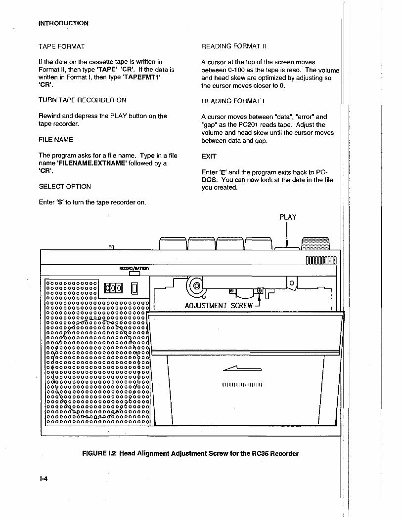
Listen to your data with the volume control onmid-range. You should adjust the skew positiof the head if the data sounds mutfled.lmproper head skew attenuates the highfrequency response of the tape recorder. Theadjustment screw is near the head assembly(Figure 1.2) and can be adjusted back and forthuntil you hear the crispest sounding data whichindicates maximum high frequency response.
CONNECT
Connect the two cables from the tape recorderMONITOR (labeled EAR on the Model RC35(Realistic CTR-85)) and REM to the PC201monitor and remote located on the back panel.
4.4
/,-2

INTRODUCTION
IE
Interrupt Selection Jumper
(Location P43)
Dip Switches
(Location M36)
o'!i @
l-3
FIGURE 1.1 Location of PC201 Card Address Switch & Interrupt Jumper
INTRODUCTION
TAPE FORMAT
lf the data on the cassette tape is written inFormat ll, then type 'TAPE' 'CR'. lf the data iswritten in Format l, then type'TAPEFMTI''cR'.
TURN TAPE RECORDER ON
Rewind and depress the PLAY button on thetape recorder.
FILE NAME
The program asks for a file name. Type in a filename'FILENAME.EXTNAME' followed by a'cR'.
SELECT OPTION
Enter 'S'to turn the tape recorder on.
READING FORMAT II
A cursor at the top of the screen movesbetween 0-100 as the tape is read. The volumeand head skew are optimized by adjusting sothe cursor moves closer to 0.
READING FORMAT I
A cursor moves between udatan, 'error" and"gap" as the PC201 reads tape. Adjust thevolume and head skew until the cursor movesbetween data and gap.
EXIT
Enter'E' and the program exits back to PC-DOS. You can now look at the data in the fileyou created.
PLAY
oooooooooooooo ooooooo ooooooooooooooooooooooooooooooooooooooooooooooooooooooooooooooooooooooooooooooooooooooooooooooooo o o o o ooo o o0-o! o o o o o o o o o oo o o o o oog,fo o o o dbo o o o o o o ooo o ooo'd o oo oo o o o obo o o o o oooooy'ooooooo o oooo\o oooo ooo/o o o o oo o o o o o o o o ob o o oo oo16 o o o o o o o o o o o o o o o doo oootooooooooooooooooobooo op o oooo o oo o o o o o o o o o o\o ooqooooooooooooooooooo9oooooooooooooooooooooooooOooooooooooooooooooodooqoooooooooooooooooooooooooooooooooooooooooooood.o o oo oo o ooo o o o o o o o o o 0 oodooooooooooooooooooobooopo oo o o ooo o o o o o o o oo dooooqooooooooo o ooo oooopooooooQooooooooooooooooooooooo\ooooooooooooo 96ooooooooo\oooooo o oo oo9ooooooo ooo oor\Q o o o o o oo q.9o o o o o o oo ooo oo o dbooooo cl-o o o oo o oooooooooooooooooooooooooo
l-4
FIGURE 1.2 Head Alignment Adjustment Screw for the RC35 Recorder
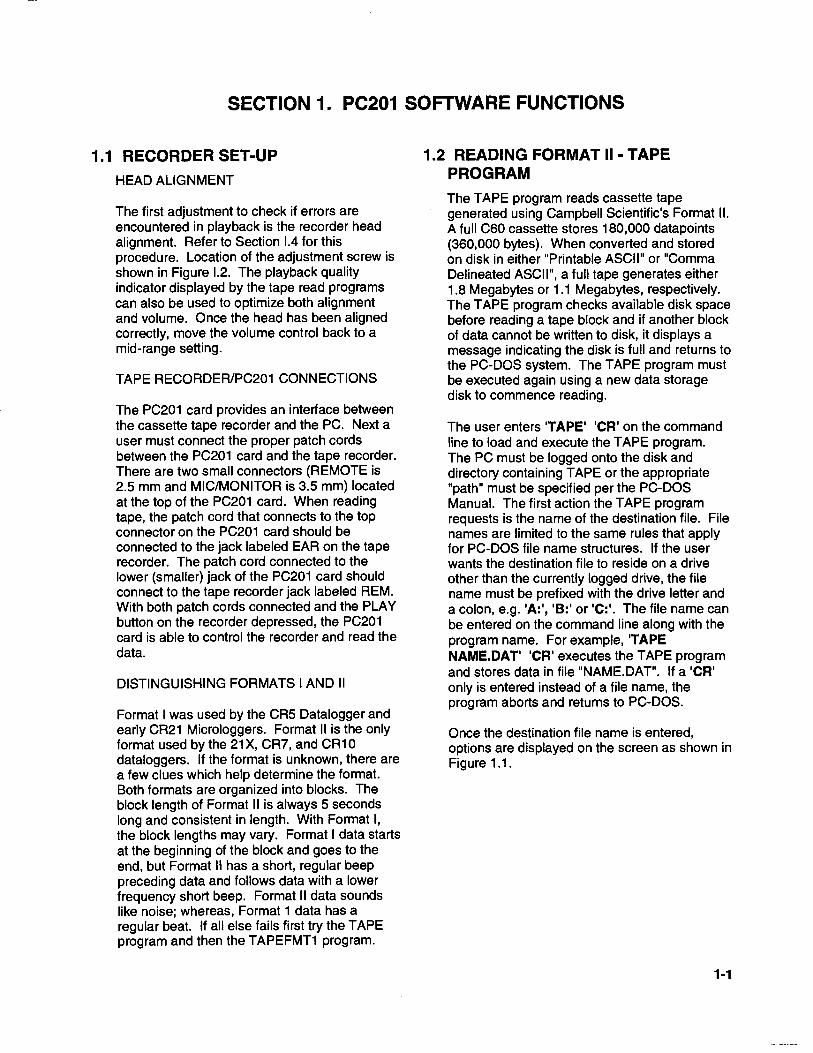
SECTION 1, PC2O1 SOFTWARE FUNCTIONS
1.1 RECORDER SET.UP
HEAD ALIGNMENT
The first adjustment to check if errors areencountered in playback is the recorder headalignment. Refer to Section 1.4 for thisprocedure. Location of the adjustment screw isshown in Figure 1.2. The playback qualityindicator displayed by the tape read programscan also be used to optimize both alignmentand volume. Once the head has been alignedcorrectly, move the volume control back to amid-range setting.
TAPE RECORDER/PC2O1 CONNECTIONS
The PC201 card provides an interface betweenthe cassette tape recorder and the PC. Next auser must connect the proper patch cordsbetween the PC201 card and the tape recorder.There are two smallconnectors (REMOTE is2.5 mm and MIC/MONITOR is 3.5 mm) locatedat the top of the PC201 card. When readingtape, the patch cord that connects to the topconnector on the PC201 card should beconnected to the iack labeled EAR on the taperecorder. The patch cord connected to thelower (smaller) jack of the PC201 card shouldconnect to the tape recorder jack labeled REM.With both patch cords connected and the PLAYbutton on the recorder depressed, the PC201card is able to control the recorder and read thedata.
DISTINGUISHING FORMATS IAND II
Format I was used by the CRS Datalogger andearly CR21 Microloggers. Format ll is the onlyformat used by the 21X, CR7, and CRl0dataloggers. lf the format is unknown, there area few clues which help determine the format.Both formats are organized into blocks. Theblock length of Format ll is always 5 secondslong and consistent in length. With Format l,the block lengths may vary. Format I data startsat the beginning of the block and goes to theend, but Format ll has a short, regular beeppreceding data and follows data with a lowerfrequency short beep. Format ll data soundslike noise;whereas, Format 'l data has aregular beat. lf allelse fails first try the TAPEprogram and then the TAPEFMTI program.
1.2 READING FORMAT II . TAPEPROGRAM
The TAPE program reads cassette tapegenerated using Campbell Scientific's Format ll.A full C60 cassette stores 180,000 datapoints(360,000 bytes). When conveded and storedon disk in either "Printable ASC|l" or "CommaDelineated ASC|l", a fulltape generates either1.8 Megabytes or 1.1 Megabytes, respectively.The TAPE program checks available disk spacebefore reading a tape block and if another blockof data cannot be written to disk, it displays amessage indicating the disk is full and returns tothe PC-DOS system. The TAPE program mustbe executed again using a new data storagedisk to commence reading.
The user enters 'TAPE' 'CR'on the commandline to load and execute the TAPE program.The PC must be logged onto the disk anddirectory containing TAPE or the appropriate"path" must be specified per the PC-DOSManual. The first action the TAPE programrequests is the name of the destination file. Filenames are limited to the same rules that applyfor PC-DOS file name structures. lf the userwants the destination file to reside on a driveother than the currently logged drive, the filename must be prefixed with the drive letter anda colon, e.g. 'A:', 'B:'or'C:'. The file name canbe entered on the command line along with theprogram name. For example, 'TAPENAME.DAT' 'CR'executes the TAPE programand stores data in file "NAME.DAT". lf a'CR'only is entered instead of a file name, theprogram aborts and returns to Pc-Dos.
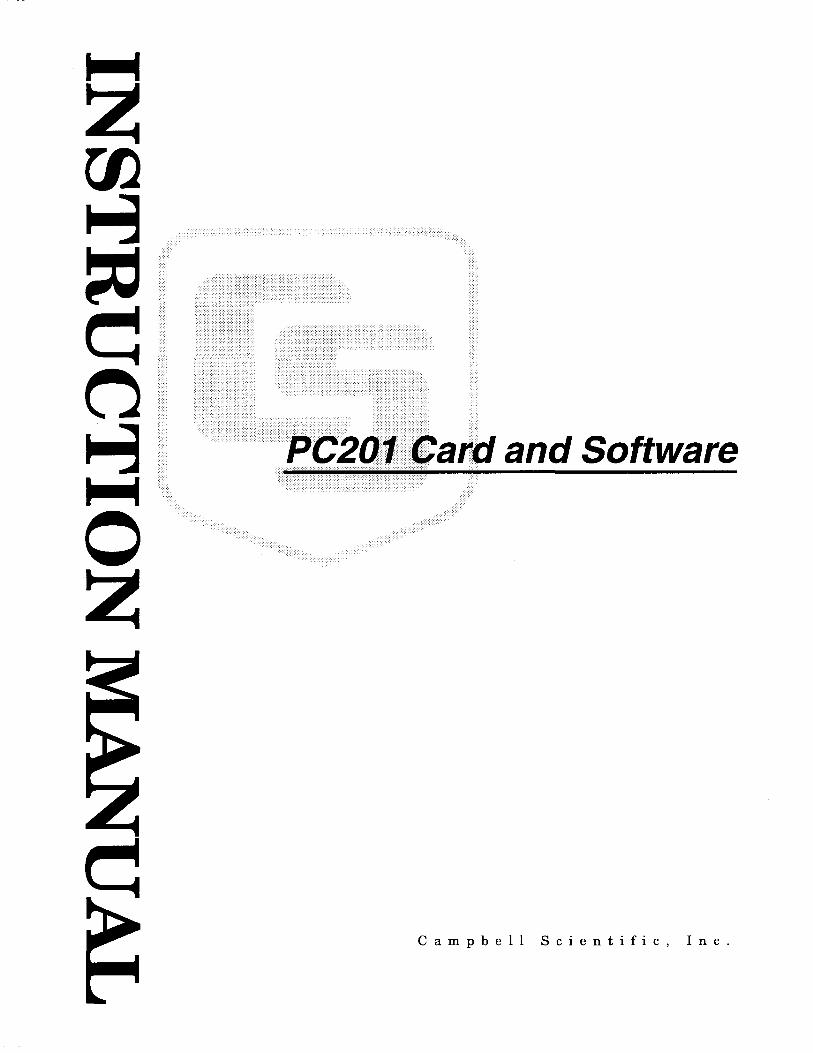
Once the destination file name is entered,options are displayed on the screen as shown inFigure 1.1.
1-1

SECTION 1. PC2O1 SOFTWARE FUNCTIONS
Maximum Timing Deviation("/o of timing margin)
0 10 20 30 40 50 60 70 80 90 100
Options
F = Ghange File Name
Bit Gell= ps€c
Current Values
D = Change File Data FormatG = Change Allow. Gap TimeS = Start ReadingR = Restart ReadingE = Exit
Select option:
NAME.DATc. D. ASCil5 secondsNot Reading
FIGURE 1.1 TAPE Program Screen Display
1,2,1 DESCRIPTION OF OPTIONS
The "Current Values" shown in Figure 1.1 arethe default settings of each option listed on theleft side of the screen. To change any of thedefault settings, enter the letter to the left of theequal sign i.e. 'F', 'D', 'G', etc. lf an option isselected while the PC201 card is reading, theTAPE program may take up to five seconds torespond. A detailed description of each optionis given below:
CHANGE FILE NAME
'F'option: any legalfile name
This option clears existing date butfers, closesthe current data file and opens the new file. Aprompt asks for the new destination file. lf onlya'CR' is entered, the program aborts andreturns the user to the PC-DOS system. Tostart a new file, type 'NEWFILENAME' 'CR'and the new file will appear as the "CurrentValues" parameter.
CHANGE FILE DATA FORMAT
'D'option: Comma Delineated ASCIIPrintable ASCIISame As On Tape
One of the three format options is selected bytoggling the "D" key.
"Comma Delineated ASC|l" strips all lDs,leading zeros, unnecessary decimal points, plus
1-2
signs, and spaces. Data points are separatedby commas. Output arrays are separated bycarriage return, line feed.3
1,234,1 1 45,23.65,- 1 2.26,625.9
1,234,12OO,24. 1,-1 0.99,650.3
"Comma Delineated ASC|l" averages about 6bytes per datapoint.
"Printable ASCII' is the standard dataloggerASCII output described in the dataloggermanual. Each 10 character datapoint containsa 2 digit lD, polarity sign, decimal point and 2spaces following the value. An example of"Printable ASCIl" is shown below:
01+0001 . 02+0234. 03+1114504+23.65 05-'12.26 06+625.901+0001. Q2+0234. 04+1200.04+24.14 05-10.98 06+650.3
The end of each Output Array or every eightdatapoints (80 characters) is followed by acarriage return, line feed.
"Same as on Tape" stores data in the fileexactly as it is received from the tape.Selecting this option when reading Format lldatalogger tapes stores the data in CSI's binaryFinal Storage Format, described in the CR7X,21X, or CR10 Operator's Manual. The "Sameas on Tape" option should be selected whenreading a tape generated with the TAPEWRprogram or CSI's C20 Cassette Interface.
CHANGE ALLOWABLE GAP TIME
'G' option: any integer from 0 (infinite gap) to59 seconds
The gap time is the time between data blockson tape, 1.5 seconds for data tapes from CSI'sdataloggers. The default setting for theallowable gap time is 5 seconds. Whenever theTAPE program detects a gap which exceedsthe allowable gap time, it stops reading andallows a file name change before reading thenext group of data. To separate groups of datawhen logging, pull out the REM jack and recorda longer than normal gap.

START READING
'S'option: none
Entering 'S' stafts the recorder and initiates thereading and storing of data to the disk. The"option" description changes to "Stop Reading"and "Current Value" changes to "Reading" when'S'is selected. The "Option" and "CurrentValue" displays change back again if 'S' istoggled or the gap time is exceeded.
RESTART READING
'R'option: none
At the beginning of a tape read operation, it isoften necessary to make adjustments in a trialrun. This option is used to reinitialize the fileafter adjustments have been made. A promptappears that allows you to rewind the recorder,confirm the "Restart", and start over. Datapreviously written into the file is erased.
EXIT
'E'option: none
This option terminates the TAPE programexecution. Data buffers are cleared and thedestination file is closed before termination.
1.2.2 PAYBACK OUALITY INDICATORS
Playback quality information is displayed on thescreen as an aid in making recorderadjustments. The timing for each voltagetransition detected by the PC201 card iscompared with what it ideally should be. Every16 words (32 bytes) the maximum timingdeviation from the ideal is displayed on thescreen. The displayed units are in thepercentage of allowable timing margin. lf thetiming deviation reaches 100o/o then one ormore of the last 16 words are in error. The 512word tape block contains an elaborate parityarray which allows correction of read errors upto a certain point. lf uncorrectable errors aredetected, the block number and the number ofuncorrectable errors are displayed on the lowerpart of the screen.
The PC indicates the period of one bit cell at thestart of a block of data in microseconds (ps). Abit cell is the tape space required to store onebit of information. This is useful only if your
SECTION 1. PC2O1 SOFTWARE FUNCTIONS
tape recorder has speed adjustment capability.With Format ll a bit cell should be 256 ps long.A value of 256, plus or minus 30o/o, should bereadable. As the tape speed is increased,timing errors increase, causing data read errors.
1.3 READING FORMAT I . TAPEFMT1PROGRAM
The TAPEFMT1 program is used to read CSI'sFormat I tapes. The prompts and options forTAPEFMTI are about the same as those usedin the TAPE program. Refer to Section 1.2lorinformation on how to use the options. Format I
is recorded in ASCII so no conversion optionsare available.
No timing deviation is used with Format I but a"Read Status" is displayed in the upper righthand corner of the screen. As the PC201 readsthe tape, a cursor moves from "Gap" to "Data"or from "Gap" to "Error". lf the cursor moves tothe "Error" condition, a read error has occurred.Read errors on Format I tapes occur forindividual characters and are indicated by a "?"in the data file. A block number and the numberof errors are displayed on the lower part of thescreen.
1.4 WRITING TO TAPE - TAPEWRPROGRAM
The TAPEWR program is used to write a diskfile to cassette tape using CSI's tape Format ll.The TAPEWR program will not write to tape inFormat L This program is useful for transferringfiles between computers that both supportFormat ll. Tapes written with this program canbe read using the TAPE program, specifying the"Same as on Tape" option or the Model C20Cassette lnterface. Data is written in 512 wordblocks (1024 bytes) with each byte maintainingall eight bits of the original information. lf thedisk file is not an even multiple of 1024 bytes,nulls are used to fill out the last btock.
When writing to tape the patch cord connectedto the top (larger) connector of the PC201 cardmust be connected to the MIC (or CMT lN)connector on the tape recorder. Push theRECORD and PLAY buttons with the REMOTEpatch cord unplugged to advance past theleader at the start of the tape. Connect theREMOTE cord and type'TAPEWR' 'CR'.Enter the name of the file to be written to tape.When the tape recorder is prepared enter'CR'
1-3

SECTION 1. PC2O1 SOFTWARE FUNCTIONS
to start writing. The tape is controlled by thePC201 until the source file is written to tape, atwhich time the program returns the user to thePC-DOS system.
The screen displays:
Campbell Scientific Tape Write - Version 3
Enter source file name: 'FILENAME' 'CR'
1.5 USING THE PC2O1 CLOCK1.5.1 CLKTOTBM
This program uses the battery powered clockon CSI's PC201 Card to set the IBM clock withthe date and time. Generally this program iscalled from the AUTOEXEC.BAT file andexecuted at power up to set the PC clock.Thereafter, any time or date information neededby the operating system or programs running onthe PC can be obtained from the standard PCclock. The CLKTOIBM program is a machinecode program and can be executed by typing'CLKTOIBM' 'CR'on the PC-DOS commandline. After execution the program returns to thePC-DOS system with a message that the clockhas been set.
1.5.2 TBMTOCLK
This program reads the standard PC clock andsets the battery powered PC201 clock with thedate and time. This program is used to set theproper time and date into the PC201 clock andshould be needed infrequently. The procedurerequires running the DATE and TIME programssupplied with PC-DOS to set the PC clock.Execute the IBMTOCLK program to set theclock on the PC201 card by typing 'IBMTOCLK''CR' as a PC-DOS command. After executionthe program returns to the PC-DOS system witha message that the clock has been set.
1.6 CHECKING BATTERY STATUS
This program checks the status of the batteriesin the PC201 Card. The two I'AAA" batteries willlast approximately two years on a full charge.To execute the program, type'BATTERY' 'CR'.The program issues a message regarding thebattery status, then returns to the PC-DOSsystem.
1-4
CAUTION: The battery check will be validonly if the batteries are installed. An opencircuit will not return a proper battery status
1.7 FILE SIGNATURE CHECK . SIGPROGRAM
This program will give the signature of a file.This signature will not change unless the filehas been changed in some way. This is usedverify a proper copy has been made. Toexecute the program, type'SlG FILENAME''CR'. The program will give the file namefollowed by the file size (in bytes), creation datetime and the signature.

SECTION 2. PC2O1 TECHNICAL REFERENCE
The PC201 Clock, Tape & Serial I/O Card provides the hardware necessary to read or write CampbellScientific casseffe data tapes and aid in unattended operation of the IBM PC. The card contains abattery backed up realtime clock and an asynchronous serialcommunications port which may beconfigured as COM|, COMZ, COM3, or COM4. The PC201 is addressable to any l/O address in the PCl/O map, but supporting software must be changed if addresses otherthan COMI, COMZ, COM?, orCOM4 are used. The softttrare clock is implemented with the 63A3 processor. lf the PC2O3 Power-upControl Box is connected to the PC201, the clock is synchronized to the 50 Hz or 60 Hz signaloriginating from the 115 VAC power line. When the AC signal is not available, the clock is maintained bya baftery powered 16.384 kHz crystal oscillator on the PC201 card. The two alkaline 'AAA' cell batteriesshould be replaced every two years. The clock can be set with IBMTOCLK and read with CLKTOIBM.The status of the battery can be checked by reading the status byte from the PC201 card. Clockaccuracy without the PC203 is *3 minutes per month. With the PC203, accuracy is equal to theaccuracy of 60 Hz.
The asynchronous serial communications port is designed to be functionally equivalent to the IBMAsynchronous Communications Adapter with a couple of exceptions. The OUT| modem control linefrom the 8250 UART on the standard IBM card is not used. The PC201 uses this output to interrupt the6303 processor, causing it to abort a current command and insuring its attention prior to issuing the 6303a command. Another difference is that the PC20l card does not provide a current loop option for serialcommunications. The PC201 card is equipped with a 34 pin rectangular connector designed to providea standard R5232 port when proper cabling is used. Other conductors on the 34 pin connector are usedin conjunction with eitherthe PC203 Power-up Control Box or the Campbell Scientific 9 pin intefiace.The 9 pin inbrtace may be used directly with CampbellScientific's Model SM16/5M64 or 5M192/5M716Storage Modules.
Tape read/write circuitry provided on the PC201 card reads or writes to Campbell Scientific datacassefte tapes. Specific commands are not provided in the 6303 ROM to accomplish tape read/writefunctions, but commands are provided to down load and execute 6303 code from the PC. This methodallows flexibility forfuture variations in tape formats without requiring ROM alterations.
lnformation regarding unaftended operation is contained in the PC208 Datalogger Support SoftwareManual; a brief summary of capabilities is included here. Softvvare associated with these functions iscontained on the PC208 diskette. ln combination with the PC203 Power-up ControlBox, the PC can bepowered up at a predetermined time, execute a program, and power down without user assistance. Awatch dog function is included which powers the system down, then up, if it is not progressing properlydue to a momentary power failure or program error. Power-up software allows the PC to execute agiven program at a given time with a watch dog to ensure the proper completion of that program.
Another function built into the PC20l card is the ability to use the PC to answer an incoming call. Toaccomplish this the PC20l card must be connected to the PC203 Power Controller box, which in turn isconnected to a suitable modem such as the Hayes Smaftmodem. The modem must be set to the answermode with its power left on. An incoming callactivates the modem Ring lndicator line which is sensedby the PC201 card. The PC201 card, in tum, powers up the PC through the PC203 and activates theData Terminal Ready line to the modem. The modem answers the call when it senses the DTR lineactive and sets the Carrier Detect line after establishing the carrier signal. At the time the Ring lndicatoris sensed, the PC201 card sets a timer to thirty seconds and powers the PC on. lf the Carrier Detect isnot sensed within this time, the PC is turned off. When the Carrier Detect is sensed by the PC201 card,the timer is inhibited from counting down. After the call is completed, the Carrier Detect goes in-activeand the timer counts down. Power is turned off 15 or 20 seconds later when the timer reaches zero.
2-1
SECTION 2. PC2O1 TECHNICAL REFERENCE
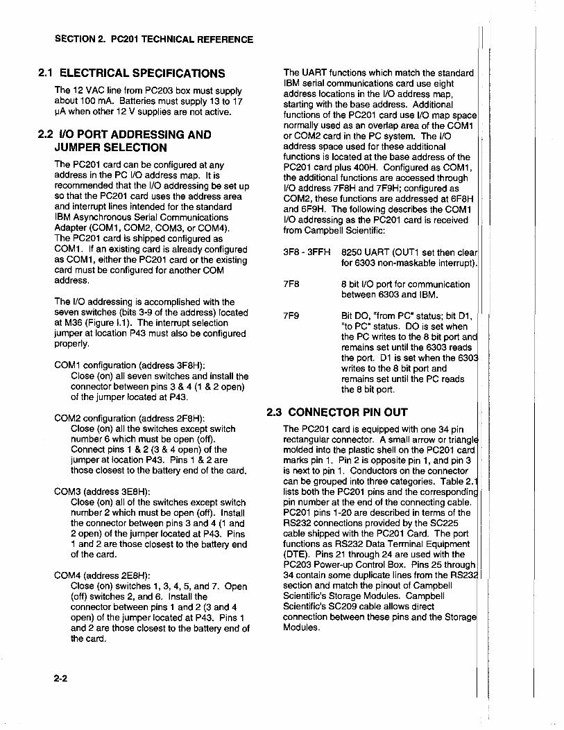
2.1 ELECTRICAL SPECIFICATIONSThe 12 VAC line from PC203 box must supplyabout 100 mA. Batteries must supply 13 to 17pA when other 12 V supplies are not active.
2.2 Irc PORT ADDRESSING ANDJUMPER SELECTION
The PC201 card can be configured at anyaddress in the PC l/O address map. lt isrecommended that the l/O addressing be set upso that the PC201 card uses the address areaand interrupt lines intended for the standardIBM Asynchronous Serial CommunicationsAdapter (COM1, COM2, COM3, or COM4).The PC201 card is shipped configured asCOM1. lf an existing card is already configuredas COM1, either the PC201 card or the existingcard must be configured for another COMaddress.
The l/O addressing is accomplished with theseven switches (bits 3-9 of the address) locatedat M36 (Figure 1.1). The interrupt selectionjumper at location P43 must also be configuredproperly.
COMl configuration (address 3F8H):Close (on) all seven switches and installtheconnector between pins 3 & 4 (1 & 2 open)of the jumper located atP43.
COM2 configuration (address 2F8H):Close (on) allthe switches except switchnumber 6 which must be open (off).Connect pins 1 & 2 (3 & 4 open) of thejumper at location P43. Pins 1 & 2 arethose closest to the battery end of the card.
COM3 (address 3E8H):Close (on) allof the switches except switchnumber 2 which must be open (off). Installthe connector between pins 3 and 4 (1 and2 open) of the jumper located at P43. Pins1 and 2 are those closest to the battery endof the card.
COM4 (address 2E8H):Close (on) switches 1,3,4,5, and 7. Open(otf) switches 2, and 6. Installtheconnector between pins 1 and 2 (3 and 4open) of the jumper located at P43. Pins 1
and 2 are those closest to the battery end ofthe card.
The UART functions which match the standardIBM serialcommunications card use eightaddress locations in the l/O address map,starting with the base address. Additionalfunctions of the PC201 card use l/O map spacenormally used as an overlap area of the COM1or COM2 card in the PC system. The llOaddress space used for these additionalfunctions is located at the base address of thePC201 card plus 400H. Configured as COM1,the additionalfunctions are accessed throughl/O address 7F8H and 7F9H; configured asCOM2, these functions are addressed at 6F8Hand 6F9H. The following describes the COMll/O addressing as the PC201 card is receivedf rom Campbell Scientific:
3F8 - 3FFH 8250 UART (OUT1 set thenfor 6303 non-maskable interrupt)
8 bit l/O port for communicationbetween 6303 and lBM.
7F9 Bit DO, "from PC" status; bit D1,"to PC" status. DO is set whenthe PC writes to the 8 bit portremains set untilthe 6303 readsthe port. D1 is set when thewrites to the 8 bit port andremains set untilthe PC readsthe I bit port.
2.3 CONNECTOR PIN OUTThe PC201 card is equipped with one 34 pinrectangular connector. A small arrow or trimolded into the plastic shell on the PC201 cardmarks pin 1. Pin 2 is opposite pin 1, and pin 3is next to pin 1. Conductors on the connectorcan be grouped into three categories. Table 2.lists both the PC201 pins and the correspondipin number at the end of the connecting cable.PC201 pins 1-20 are described in terms of theRS232 connections provided by the SC225cable shipped with the PC201 Card. The portfunctions as RS232 Data Terminal Equipment(DTE). Pins 21 through 24 are used with thePC203 Power-up Control Box. Pins 25 through34 contain some duplicate lines from thesection and match the pinout of CampbellScientific's Storage Modules. CampbellScientific's SC209 cable allows directconnection between these pins and theModules.
2-2

The Model SC234 cable provided with thePC203 brings all 34 pins of the PC201 out tothe PC203, which has a second port for
SECTION 2. PC2O1 TECHNICAL REFERENCE
connecting RS232 and CampbellScientific 9 pinl/O devices.
TABLE 2.1 PC2O134 Pin Connector Description
PC201Pin
SignalSource
PC201Description
ConnectingEnd
RS232
I142
153
164
175
186
197
20I
21
9221023
1
2345678I
1011't21314151617181920
nc"PC201ncotherncPC201ncotherncothernc
PC201otherncncotherncnc
RS232
Ground
Txd - Transmitted data
Rxd - Received data
RTS - Request To Send
CTS - Clear To Send
DSR - Data Set Ready
GroundDTR - Data Terminal ReadyRLSD - Receive Line Signal Detect
Rl - Ring Indicator
PC203
Power Switch Status, +5 V if switch is onPower Control, +5 V turns on relay.13.5 VAC supply & time base for PC201 card.Ground.
cs!9 ptN t/o ----------- -------csl I PIN lio-------
+5 VDC from PC bus.Printer Enable, same as RTS.Ground.Unload Enable, same as DTR.Ring, same as Rl.+12 VDC from PC bus.Rxd, same as Rxd.Txd, same as Txd.Modem Enable, controlled by 6303.
21222324
PC203PC201PC203
1
62738495
25262728293031323334
PC201PC2o1
PC201otherPC201otherPC201PC201nc
*nc - no connect to PC201 circuitry.
2-3
SECTION 2. PC2O1 TECHNICAL REFERENCE
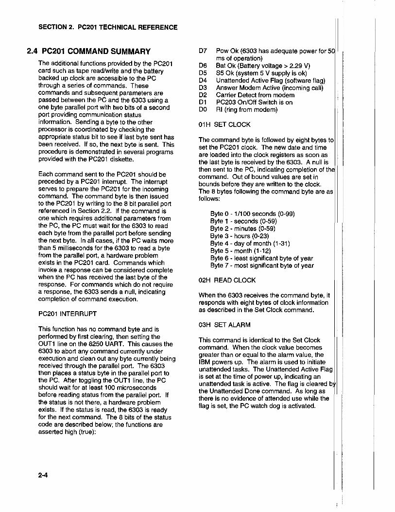
2.4 PC2O1 COMMAND SUMMARYThe additional functions provided by the PC201card such as tape read/write and the batterybacked up clock are accessible to the PCthrough a series of commands. Thesecommands and subsequent parameters arepassed between the PC and the 6303 using aone byte parallelport with two bits of a secondport providing commu nication statusinformation. Sending a byte to the otherprocessor is coordinated by checking theappropriate status bit to see if last byte sent hasbeen received. lf so, the next byte is sent. Thisprocedure is demonstrated in several programsprovided with the PC2O1 diskette.
Each command sent to the PC201 should bepreceded by a PC201 interrupt. The interruptserves to prepare the PC201 for the incomingcommand. The command byte is then issuedto the PC201 by writing to the I bit parallel portreferenced in Section 2.2. lt the command isone which requires additional parameters fromthe PC, the PC must wait for the 6303 to readeach byte from the parallel port before sendingthe next byte. In allcases, if the PC waits morethan 5 milliseconds for the 6303 to read a bytefrom the parallel port, a hardware problemexists in the PC201 card. Commands whichinvoke a response can be considered completewhen the PC has received the last byte of theresponse. For commands which do not requirea response, the 6303 sends a null, indicatingcompletion of command execution.
PC2O1 INTERRUPT
This function has no command byte and isperformed by first clearing, then setting theOUT1 line on the 8250 UART. This causes the6303 to abort any command currently underexecution and clean out any byte currently beingreceived through the parallel port. The 6303then places a status byte in the parallel port tothe PC. After toggling the OUT1 line, the PCshould wait for at least 100 microsecondsbefore reading status from the parallelport. lfthe status is not there, a hardware problemexists. lf the status is read, the 6303 is readyfor the next command. The 8 bits of the statuscode are described below; the functions areasserted high (true):
D7 Pow Ok (6303 has adequate power forms of operation)
DO Bat Ok (Battery voltage > 2.29V\D5 55 Ok (system 5 V supply is ok)D4 Unattended Active Flag (software flag)D3 Answer Modem Active (incoming call)D2 Carrier Detect from modemDl PC203 On/Off Switch is onD0 Rl (ring from modem)
01H SET CLOCK
The command byte is followed by eight bytes toset the PC201 clock. The new date and timeare loaded into the clock registers as soon asthe last byte is received by the 6303. A null isthen sent to the PC, indicating completion ofcommand. Out of bound values are set inbounds before they are written to the clock.The 8 bytes following the command byte are asfollows:
Byte 0 - 1/100 seconds (0-99)Bytel-seconds(0-59)Byte2-minutes(0-59)Byte3-hours(0-23)Byte 4 - day of month (1-31)Byte5-month(1-12)Byte 6 - least significant byte of yearByte 7 - most significant byte of year
O2H READ CLOCK
When the 6303 receives the command byte, itresponds with eight bytes of clock informationas described in the Set Clock command.
O3H SETALARM
This command is identicalto the Set Clockcommand. When the clock value becomesgreater than or equal to the alarm value, theIBM powers up. The alarm is used to initiateunattended tasks. The Unattended Active Flagis set at the time of power up, indicating anunattended task is active. The flag is clearedthe Unattended Done command. As long asthere is no evidence of attended use while theflag is set, the PC watch dog is activated.
2-4

O4H READALARM
Same as Read Clock command except thatAlarm data is returned.
OsH UNATTENDED DONE
lf a power failure occurs during unattendedoperation, the Unattended Active Flag ischecked when power returns to determine theprevious state of the PC. Executing thiscommand clears the flag, indicating to the 6303that the unattended job is done and the powercan be turned otf if there is no evidence ofattended use. Once the flag is cleared, the6303 issues a nullto the PC, indicatingcompletion of the command. Altering the alarmdoes not alter this flag.
lf the PC power is left on allthe time, the taskexecution on the PC must check the alarm time,execute the task at the proper time, andmaintain the watch dog. The Unattended ActiveFlag remains set and power on as long as theUnattended Done command is not executed. lfa problem occurs, the watch dog powers thecomputer down, then up, if the UnattendedActive Flag remains active.
O6H SET WATCH DOG TIMER
This command sets the watch dog timer,allowing enough time to execute the next taskduring unattended operation. Three eventscause the PC201 to power up the PC. Two ofthem, the switch on the Power-up Control Boxand the Ring lndicator signalof an answermodem, are considered attended activitieswhere the user can fix potential problems.When the alarm function powers up the PC it isconsidered unattended operation, requiring awatch dog to power down-power up reset thesystem in the event of failure. The watch dog isa timer which must be continuously reset duringnormal execution. When the PC powers up, thetimer is automatically loaded with the samevalue as when last set.
The command byte is lollowed by a 2 byteinteger, Least Significant Byte (LSB) first,which is the number of seconds before thecomputer is reset. After receiving the secondbyte, the 6303 responds with a nullto indicatethe command is complete. lf the maximumcount (FFFFH) is set into the timer, thecomputer never resets.
SECTION 2. PC2O1 TECHNICAL REFERENCE
WARNING: 120 seconds may beinadequate for the PC to execute its power-up memory test and initialization phase,prohibiting setting the watch dog again. Forthis reason, never set the timer to less than120 seconds.
O7H READ ERROR LOG
System errors detected by the PC201 arerecorded, along with the time of occurrence, inan error log. Only the most recent error code iskept along with the total number of errors thathave occurred. The error log is obtained byusing this command.
The returned bytes are as follows:
Byte0-ErrorCounter.Byte 1 - Error Code of most recent error.
00H - No errors have been logged.01H - System power did not come on
when relay was activated.02H - PC watch dog did not get reset
on time, or 6303 crashed.03H - AC power failure occurred while
system was active.
--------------Time of Most Recent Error-------------
Byte 2 - 1/100 seconds (0-99)Byte3-seconds(0-59)Byte4-minutes(0-59)Byte5-hours(0-23)Byte 6 - Day of Month (1-31)ByteT-Month(1-12)Byte 8 - Least significant byte of YearByte 9 - Most significant byte of Year
O8H CLEAR ERROR LOG
This command clears Error Counter and ErrorLog then sends a null.
2-5


APPENDIX A. CAMPBELL SCIENTIFICFINAL STORAGE DATA FORMAT
The Campbell Scientific FinalStorage Format is used primarily to compress datalogger data for storageon devices such as cassette tape and computer disk. The fundamental storage unit of this format is atwo byte data word. The first byte of each two byte pair is used to designate the type and use of a wordor subsequent words. Given bits ABCD EFGH where A is most significant bit of the first byte of a word,if bits D, E, and F are not all ones, then it is the first of a two byte data value. lf D, E, and F are all ones,the data type and use of other bits are as follows:
ABCD EFGH Description
1 1 11 110x Startnewarray. StartingwithHasthemostsignificantbit,therestof thiswordisused as an array lD number ranging from 0 through 511. This start of anay bytealso marks the end of either the ASCII or the 8 bit data modes.
1 1 1 1 1 1 1O Startnewarrayandbegin8bitdatamode. Thesecondbyteof thiswordisthefirst of a string of 8 bit data values which range from 0 through 251. lt will stay in
the I bit data mode untileither an end of byte mode byte is detected or untilthestart of a new array is detected.
O 1 1 1 1 1 10 BeginSbitdatamode. Thesecondbyteof thiswordisthefirstof astringof Sbitdata values which range from 0 through 251.
O 1 1 1 1 101 BeginASClldatamode. Thesecondbyteof thiswordisthefirstof astringofASCII characters. lt will stay in the ASCII data mode until either an end of bytemode byte is detected or until the start of a new array is detected.
1 1 1 1 1 1 1 1 Endof bytemodecharacter. Thisbyteisusedtomarktheendof either8bitdataor ASCII data. lt is required only when the next byte in memory is either not thestart of a new array or not on an even word boundary. lt this byte is the first byteof a word, then the second byte of the word must be the same as the first andacts as a till byte.
x x 0 1 1 1 x x Firstbyteof a4 bytevalue.
0 0 1 1 1 1 x x Third byteof a4 bytevalue.
O 1 1 1 1 1 1 1 Fillword. Thefillwordisusedtofilltheendof ablockwhenitisnecessarytowrite an incomplete block of data to tape. While reading, data fill words should beignored; they are not part of the data. ln some cases it may be necessary to keepextra information for special programs which operate on data files. The secondbyte ol the tillword can be any value and is a good place to keep extra informationthat is not part of the data but must be kept with the data for special programs.
O 1 1 1 1 1 O O Errorword. Errorwords will occur in data which has been read from tape in whichirrecoverable errors were detected. The second byte is always zero.
A-1

APPENDIX A. CAMPBELL SCIENTIFIC FINAL STORAGE DATA FORMAT
Two Byte Data Format
lf bits D, E, and F are not all ones, then the value is a two byte number as follows:
Bits Descriotion
A Polarity,0="+", 1="-".
B,C Decimallocators.
D through H Bits 12 through 8 resp. of binary mantissa.
2nd byte Bits 7 through 0 of binary mantissa.
The decimal locators can be thought of as a negative base 10 exponent with decimal locations asfollows:
B C Decimal location
0 0 xxxx.
0 1 xxx.x
1 0 xx.xx
1 1 x.xxx
The decimal range of the mantissa is 0 to 6999.
Four Byte Data Format
1st b$e 2nd byte 3rd byte 4th byte
AB01 1lCD xxxxxxxx 0011 11EF xxxxxxxx
Bits or byte Descriotion
B Polarity,0="+", 1="-".
C, D, A Decimalexponent.
E, F Bits 17 and 16 resp. of binary mantissa.
2nd byte Bits 15-8 of binary mantissa.
4th byte Bits 7-0 of binary mantissa.
Interpretation of the decimal exponent is as follows:
Bits DecimallocationCDA
0 0 0 xxxxx.0 0 1 xxxx.x0 1 0 xxx.xx0 1 1 xx.xxx1 0 0 x.xxxx1 0 1 .xxxxx
The exponent is actually a binary value indicating the negative decimal exponent.
A-2
APPENDIX B. CAMPBELL SCIENTIFICPRINTABLE ASCII DATA FORMAT
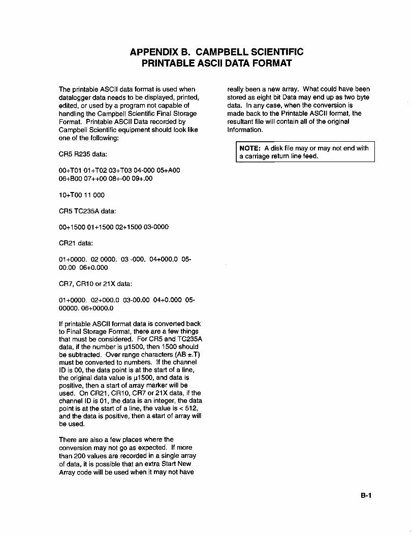
The printable ASCII data format is used whendatalogger data needs to be displayed, printed,edited, or used by a program not capable ofhandling the Campbell Scientific Final StorageFormat. Printable ASCII Data recorded byCampbell Scientific equipment should look likeone of the following:
CR5 R235 data:
00+T01 01 +T02 03+T03 04-000 05+A0006+800 07++00 08+-00 09+.00
10+T00 11 000
CR5 TC235A data:
00+1500 01+1500 02+1500 03-0000
CR21 data:
01+0000. 02 0000. 03 -000. 04+000.0 05-00.00 06+0.000
CR7, CR10 or 21X data:
01+0000. 02+000.0 03-00.00 04+0.000 05-00000.06+0000.0
lf printable ASC|lformat data is converted backto Final Storage Format, there are a few thingsthat must be considered. For CR5 and TC235Adata, if the number is p1500, then 1500 shouldbe subtracted. Over range characters (AB *.T)must be conveded to numbers. lf the channellD is 00, the data point is at the start of a line,the original data value is p1500, and data ispositive, then a start of array marker will beused. On CR21, CR10, CR7 or 21X data, if thechannel lD is 01, the data is an integer, the datapoint is at the start of a line, the value is < 512,and the data is positive, then a start of array willbe used.
There are also a few places where theconversion may not go as expected. lf morethan 200 values are recorded in a single arrayof data, it is possible that an extra Start NewArray code will be used when it may not have
really been a new array. What could have beenstored as eight bit Data may end up as two bytedata. In any case, when the conversion ismade back to the Printable Ascll format, theresultant file will contain all of the originallnformation.
NOTE: A disk file may or may not end witha carriage return line feed.
B-1


APPENDIX C. CAMPBELL SCIENTIFIC COMMA DELINEATED ASCII
Comma Delineated ASClldata separates datavalues with commas and separates arrays by acarriage return line feed. All unnecessaryleading and trailing zeros, decimal points, andplus signs are removed as well as output lDs.
NOTE: A disk file may or may not end witha carriage return line feed.
c-1


APPENDIX D. USE OF COM3 AND COM4
The addresses and interrupts used by the PC201 software are given in the following Table. Earlierversions of the PC201 software used ditferent addresses and interrupts.
ComPort
TABLE D.1. COM
Addresses and Interrupts(f RQ) Supported by PC201
IRO Address
coMlcoM2coM3coM4
PORT Addresses and PC201 Card Settings.
PC2O1 CARDSettings
Switch Jumper1234567
4 03F83 02F84 03E83 02E8
111111111111011011111101 1 101
3&41&23&41&2
1=CLOSED,O=OPEN
D-1


AAddressing configuration 2-2Adjusting tape recorder's skew l-2Alarm value, Setting 2-5Answering an incoming callwith PC 2-1
BBackup disk, Creating PC201 l-2Batteries
Checking status of 1-4Replacing 2-l
cC20 Cassette Interface 1-3Clear Error Log command 2-5CLKTOIBM program 1-4Clock time to datalogger, Sending PC 1-4COM ports, Applications notes on D-lComma Delineated ASCI] format
Defining C-lOption 1-2
Command entries, Entering l-1
Command summary 2-4Computer requirements l-1
Connector description, Table of 34-Pin 2-3CR key l-1
DData, Separating groups of 1-2Data format
Comma Delineated ASCII C-lFinalStorage A-1Printable ASCII B-1
Datalogger, Sending PC clock time to 1-4Date and time, Setting 2-4
EElectrical specifications 2-2Error Counter, Clearing 2-5Error Log, Clearing 2-5Executing programs l-1
Exit option 1-3
FFile, Creating new 1-2File name, Entering a l-4File signature check (SlG program) 1-4Files between computers, Transferring 1'3Final Storage data format A-1Format land ll, Distinguishing between 1-1
INDEX
Format ltapes (TAPEFMTI program),Reading 1-3
Format lltapes (TAPE program), ReadingFormat
Comma Delineated Ascll C-lFinalStorage A-1Printable ASCII B-1
GGap time, Changing allowable 1-2
HHayes Smartmodem l-1Head alignment of RC35
Figure l-4lnstructions 1-l
Il/O port addressing 2-2IBMTOCLK program 1-4Installing PC201 Card l-2lnterrupts, PC2O1 2-4Interrupts, Port l-2
LLocation of Switches & Jumpers l-3
PPC clock time to datalogger, Sending 1-4PC, Answering an incoming call 2-1PC201 Card
34-Pin connector 2-3Card lnstallation l-2Clock 1-4Head Adjustment l-4Sottware l-lSwitches & jumpers l-3
PC201.SlG file, Executing l-2PC203 Power-up Control Box l-1, 2-1Playback quality indicators 1-3Printable ASCII data format
Defining B-1Option 1-2
RRC35 Tape Recorder
Adjusting skew l-2Aligning head 1-1Connecting to PC201 l-2Figure of l-4
PC201
1-1
t-1

PC2O1 INDEX
Turning on h2Read Alarm command 2-4Read Error Log command 2-5Read PC201 Clock command 2-4Recorder, see RC35 Tape RecorderRestart Reading option 1-3RF95 RF Modem l-1
sSC225 Cable 2-2SC234 Cable 2-3Serial communication port 2-l
Configuring RS-232 l-2Set Alarm command 2-4Set PC201 Clock command 2-4Set Watch Dog Timer command 2-5SIG program 1-4Signatures, PC2O1 software file l-1Skew, Adjusting tape recorde/s l-2Software functions 1-1SRM-6A RAD Modems l-1Start Reading option 1-3System overview l-1
TTape format program, Selecting a l-4TAPE program 1-lTape reading options F2Tape recorder, see RC35 Tape RecorderTAPEFMT1 program 1-3TAPEWR program 1-3Technical reference 2-1TELCOM program l-1Telecommunication functions l-1Testing PC?O1 card l-2Time, Setting date and 2-4Transferring files between computers 1-3
UUnattended Done commandUnattended operation 2-1
VVoltage transition timing 1-3
wWatch dog timer, Setting 2-5
l-2