Embed Size (px)
Citation preview
1
Service Manual – ThermoPro Twin & Single Brewers
For the Latest speciFications and inFormation go to www.wiLburcurtis.com
Important Safeguards/ConventionsThis appliance is designed for commercial use. Any servicing other than cleaning and maintenance should be performed by an authorized Wilbur Curtis service center.• Do NOT immerse the unit in water or any other liquid• To reduce the risk of fire or electric shock, do NOT open top or side panels. No user serviceable parts inside. Repair
should be done only by authorized service personnel.• Keep hands and other items away from hot parts of unit during operation.• Never clean with scouring powders, bleach or harsh implements.
Conventions
WARNINGS – To help avoid personal injury
Important Notes/Cautions – from the factory
Sanitation Requirements
This Curtis Generation 3 Unit is Factory Pre-Set and Ready to Go… Right from the Carton.Following are the Factory Settings for your G3 Coffee Brewing Systems:
• Brew Temperature = 200°F • Water Bypass = On for LARGE & MEDIUM Brew Only
• Brew Volume = Set to Vessel Requirement. • Sleep Mode = Off
System Requirements:
• Water Source 20 – 90 PSI (Minimum Flow Rate of 1 GPM)
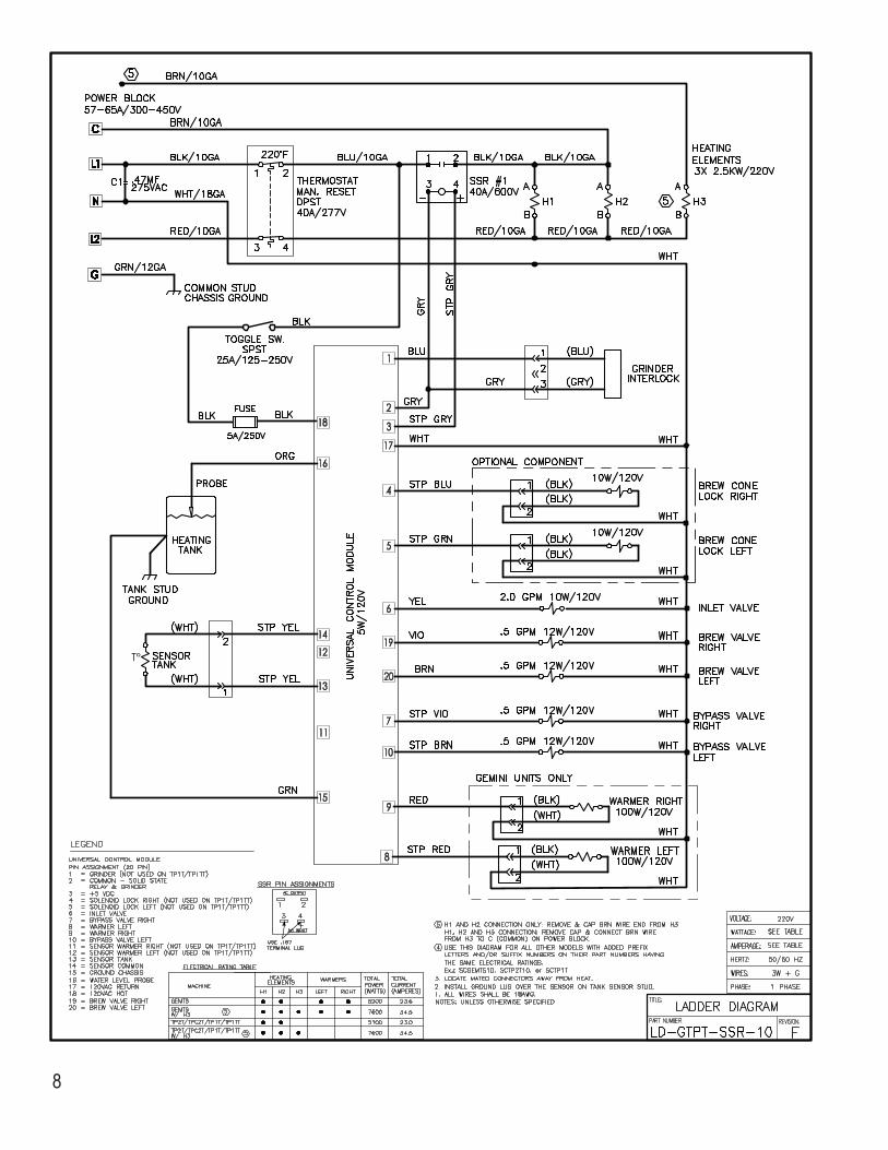
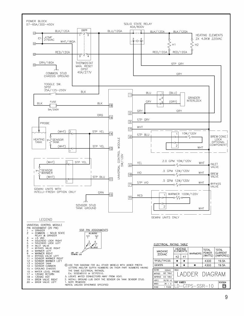
• Electrical: See attached schematic for standard model or visit www.wilburcurtis.com for your model.
1. A 3/8” NPT x 3/8” Flare elbow has been supplied for water line connection. Use tubing sized sufficiently to provide a minimum of 1.0 GPM.
2. To hookup the InterLock grinder, Locate the jack labeled “Class 2 Wiring Only” on brewer and grinder. Connect the two with the cable plug.
3. Connect the unit to an appropriate electrical power circuit.
4. Turn on the toggle (STANDBY/ON) switch behind the unit. The heating tank will start to fill. When the water level in the tank rises to the correct volume, the heating elements will energize automatically. With ADS Systems there is no danger of element burnout caused by an empty tank.
5. The heating tank will require 20 to 30 minutes to reach operating temperature (200°F). Press the ON button on the control module. When the water in the tank gets to brewing temperature, the control module screen will read Ready to Brew.
Wilbur Curtis Company, inC.
WILBUR CURTIS COMPANY Montebello, CA 90640
Models Included TP2T – ThermoPro Twin TP2S – ThermoPro Single
CAUTION: DO NOT connect this brewer to hot water. The inlet valve is
not rated for hot water.
CAUTION: Please use this setup procedure before attempting to use
this brewer. Failure to follow the instructions can result in injury or the voiding of the warranty.
ISO 9001 REGISTERED
WARNING HOT LIQUID, Scalding may occur. Avoid splashing.
IMPORTANT: Equipment to be installed to comply with applicable federal,
state, or local plumbing/electrical codes having jurisdiction.
NSF International requires the following water connection:1. A quick disconnect or additional coiled tubing (at least 2x the depth of the unit) so that the machine
can be moved for cleaning underneath.2.Thisequipmentistobeinstalledwithadequatebackflowprotectiontocomplywithapplicable
federal, state and local codes..3.Waterpipeconnectionsandfixturesdirectlyconnectedtoapotablewatersupplyshallbesized,
installed and maintained in accordance with federal, state, and local codes.
Find out more on the web.WILBURCURTIS.COM
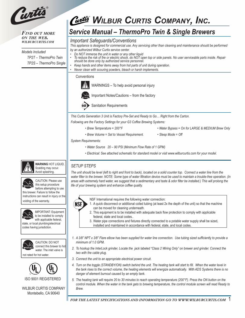
SETUP STEPSThe unit should be level (left to right and front to back), located on a solid counter top. Connect a water line from the water filter to the brewer. NOTE: Some type of water filtration device must be used to maintain a trouble-free operation. (In areas with extremely hard water, we suggest that a sedimentary and taste & odor filter be installed.) This will prolong the life of your brewing system and enhance coffee quality.
Your Curtis ADS System is Factory Pre‑Set for Optimum Performance.After connection to water and power; the rear toggle switch must be on. You will hear a beep sound, indicating power is available to the controller.
The control displays . Press ON/OFF button and the screen will display . After three seconds, is displayed.
Water will fill the tank (approximately 2-3 minutes depending on water flow rate). When the proper level is reached will appear on the screen. It takes approximately 20 minutes to reach setpoint temperature of 200°F.
Control will display when temperature reaches the setpoint (200°F); unit is at brewing temperature.
THERMO-PROWILBUR CURTIS
WILBUR CURTIS WILBUR CURTISFILLING . . .
WILBUR CURTISHEATING . . .
WILBUR CURTISREADY TO BREW
ThermoPro
Temporary label covers front UCM control module. Select batch brew before using brewer.
32
BREWING INSTRUCTIONS1. Brewer should be ON (Confirm at rear toggle switch, then press the ON/OFF button). Ready-to-Brew should be ON. If connected to an InterLock grinder;
grinder should be on.
2. Place an empty ThermoPro server under the brewcone.
6. Press Brew button. Brewing will begin immediately.
5. Transfer filled brewcone to brewer.
3. Place a clean filter into the brewcone.
4. Fill brewcone with ground coffee. If Interlocked, fill from grinder.
WARNING TO AVOID SCALDING, Do not remove brewcone while brewlightisflashing.
6. This step requires some preliminary program setting prior to brewing. You will notice that the control module (UCM) is covered with a thin white label (see illustration, above). This label is a temporary covering. It contains important batch selection instructions. Decide how many brew selections you require and follow the instructions to change the Batch Brew setting (the default is one batch).
The only way the InterLock coffee grinding system will work is with the 3-batch Model setting. If your brewer will be working with the InterLock system, you should always select the three batch setting while programming the brewer.
7. Apply the UCM control panel label. Packaged with the brewer are three labels (one batch, two batch & three batch) with brew buttons labeled LARGE, MEDIUM and SMALL. Take the label that corresponds to the brew batch you have selected and adhere this to the face of the UCM.
8. Prior to brewing, dispense 12 ounces of hot water through the hot water faucet.
9. Brew a cycle of at least 12 ounces, to purge the water lines of any air that may be trapped after filling.
10. The ThermoPro brewer is now ready for operation.
P/N
WC
-38245
Setup Steps, Continued
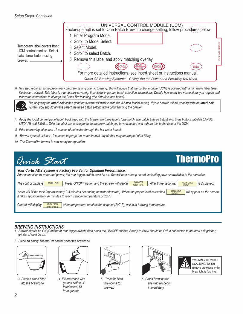
All programming selections are performed with the three center buttons. The symbols below the buttons are:
Scroll LEFT SELECTION or ENTER to save new parameter Scroll RIGHT
IMPORTANT NOTE:
32
ThermoPro Programming Guide
311
B
E
27A
54
PARTS DIAGRAM
THERMOPROTWIN BREWERTP2T
2526
1
22A2B
3456
78
13
141516
910
11
12
1718
19
20
21 22
2324
6A
6B
6C
28
29
30
31
1 2 2A 2B 3 4 5 5A 5B 6 6A 6B 6C 7 8 910111212A13141516171819202122232425262728293031
WC-5459GEM-6-102GEM-6-101GEM-6WC- 37121*WC- 844-101*WC-39442WC-39415WC-39414WC-37308WC-37259WC-3354WC-3357WC-29050*WC-58037-101WC- 847*WC-2402WC-37122*WC- 442WC- 441WC-1825WC-8559WC-8591*WC-3528WC-62030WC-37008WC-5502*WC-4382WC-5310*WC- 934-04*WC- 522*WC-43055WC-5231*WC-1438-101*WC-3765L*WC-1501WC- 102*WC-5350*WC-37176
COVER, TOP WRAPFILTER, PAPER 12¾ x 5½ (USE WITH WC-37308)FILTER, 15 x 5½” x 4¾” H (USE WITH WC-37259)FILTER, 500/PKG (USE WITH WC-3357)KIT, DUMP VALVE BREW LEFTVALVE, BY-PASS W/RESISTORLABEL, UCM OVERLAY DUAL TWIN 3-BATCHLABEL, UCM OVERLAY DUAL TWIN 2-BATCHLABEL, UCM OVERLAY DUAL TWIN 1-BATCHKIT, BREW CONE PLSTC GEM FRESH COFFEE LABELKIT, BREW CONE GOURMET PSTC FRESH COF LABELBREWCONE ASSY, GOURMET LRG CAP (OPTIONAL)BREWCONE ASSY W/BASKET (OPTIONAL)SPRAYHEAD, ADVANCED FLOWCOVER, CENTER WRAP TP 90ºVALVE, WATER INLET 2GPM 120V 10WELBOW, 3/8”FL x 3/8” M. PIPEKIT, DUMP VALVE BREW RIGHTSOLENOID, LOCK BREWCONE RIGHTSOLENOID, LOCK BREWCONE LEFT (OLDER UNITS)FAUCET, ASSEMBLY HOT WATER TP2SRELAY, SOLID STATE W/INTEGRATED HTSNKCAPACITORLEG, 4” ADJUSTABLE 3/8-16 THRD ITALIAN STYLETANK, COMPLETE TP2T ULTEM FITTINGSKIT, TANK LID ROUNDPROBE, WATER LEVELGUARD, SHOCK HEATING ELEMENTSTUBE, 5/16” I.D. X 1/8” SILICONEELEMENT, HEATING 2.5 KW 220V W/JAM NUTSTHERMOSTAT, RESETGUARD, SHOCK RESET THERMOSTATCOMPOUND, SILICONESENSOR, HEATING TANKKIT, VALVE REPAIR USE ON WC-825 & WC-826FUSE HOLDERSWITCH, TOGGLETUBE, ½ ID x 1/8W SILICONEKIT, UCM & INSTRUCTIONS LABEL
ItemNº
Part Nº Description
* Recommended parts to stock.
ILLUSTRATED PARTS LIST
THERMOPROTWIN BREWERTP2T
54
76
PARTS DIAGRAM
THERMOPROSINGLE BREWERTP2S
2627
3
1211
22A2B
6
6A
6B
28
6C
1 2 2A 2B 3 4 5 5A 5B 6 6A 6B 6C 7 8 9101112131414A151617181920212222A232424A2526272829
WC-61509GEM-6-102GEM-6-101GEM-6WC--3765L*WC- 844-101*WC-39444WC-39417WC-39416WC-37308WC-37259WC-3354WC-3357WC-29050*WC-58037-101WC- 847*WC-1501WC-37122*WC-37132*WC-1825WC-8559*WC-8556-101WC-8591*WC-3528WC-5350*WC-5851WC-5502*WC-4382WC-5310*WC- 904-04WC- 906-04*WC- 522*WC-62031WC-62032WC- 102*WC-5231*WC-1438-101*WC-37176WC-43055
COVER, TOP WRAPFILTER, 15 x 5½” x 4¾” H (USE WITH WC-37259)FILTER, 15 x 5½” x 4¾” H (USE WITH WC-37259)FILTERS, 500/PKG (USE WITH WC-3357)KIT, VALVE REPAIR USE ON WC-825 & WC-826VALVE, ADJ BY-PASSLABEL, UCM OVERLAY TP2S 3-BATCH CURTIS LABEL, UCM OVERLAY TP2S 1-BATCH CURTISLABEL, UCM OVERLAY TP2S 2-BATCH CURTISKIT, BREW CONE PLSTC GEM FRESH COFFEE LABELKIT, BREW CONE GOURMET PSTC FRESH COF LABELBREWCONE ASSY, GOURMET LRG CAP (OPTIONAL)BREWCONE ASSY W/BASKET (OPTIONAL)SPRAYHEAD ASSY, ADVANCED FLOWCOVER, CENTER WRAPVALVE, WATER INLET 2GPM 120V 10WFUSE HOLDER W/5A FUSEKIT, DUMP VALVE BREW RIGHTKIT, DUMP VALVE WC-820WC-821,WC-844FAUCET ASSY, HOT WATER TP2S/2TRELAY, SOLID STATE 40A W/HEAT SINKHEATSINK, ASSY W/OPTICAL BD (OLDER UNITS)CAPACITOR, X2LEG, 4” ADJUSTABLE 3/8-16 THRD ITALIAN STYLETUBE, ½ ID x 1/8W SILICONECOVER, TANK W/NOTCHESPROBE, WATER LEVELGUARD, SHOCK HEATING ELEMENTSTUBE, 5/16” I.D. X 1/8” SILICONE (NOT SHOWN)ELEMENT, HEATING 1.6KW 120V W/JAM NUTSELEMENT, HEATING 2KW 220V W/JAM NUTSTHERMOSTAT, RESETTANK, COMPLETE TP2S DV ULTEM FITTINGSTANK, COMPLETE TP2S ULTEM FITTINGSSWITCH, TOGGLECOMPOUND, SILICONESENSOR, HEATING TANKKIT, UCM & LABEL INSTRUCTIONSGUARD, SHOCK RESET THERMOSTAT
ItemNº
Part Nº Description
* Recommended parts to stock.
ILLUSTRATED PARTS LIST
THERMOPROSINGLE BREWERTP2S
76
98
98
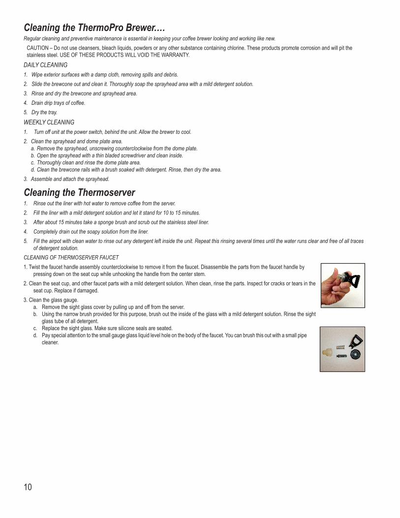
Cleaning the ThermoPro Brewer.…Regular cleaning and preventive maintenance is essential in keeping your coffee brewer looking and working like new.
CAUTION – Do not use cleansers, bleach liquids, powders or any other substance containing chlorine. These products promote corrosion and will pit the stainless steel. USE OF THESE PRODUCTS WILL VOID THE WARRANTY.
DAILY CLEANING1. Wipe exterior surfaces with a damp cloth, removing spills and debris.2. Slide the brewcone out and clean it. Thoroughly soap the sprayhead area with a mild detergent solution.3. Rinse and dry the brewcone and sprayhead area.4. Drain drip trays of coffee.5. Dry the tray.
WEEKLY CLEANING1. Turn off unit at the power switch, behind the unit. Allow the brewer to cool.2. Clean the sprayhead and dome plate area. a. Remove the sprayhead, unscrewing counterclockwise from the dome plate. b. Open the sprayhead with a thin bladed screwdriver and clean inside. c. Thoroughly clean and rinse the dome plate area. d. Clean the brewcone rails with a brush soaked with detergent. Rinse, then dry the area.3. Assemble and attach the sprayhead.
Cleaning the Thermoserver1. Rinse out the liner with hot water to remove coffee from the server. 2. Fill the liner with a mild detergent solution and let it stand for 10 to 15 minutes. 3. After about 15 minutes take a sponge brush and scrub out the stainless steel liner. 4. Completely drain out the soapy solution from the liner. 5. Fill the airpot with clean water to rinse out any detergent left inside the unit. Repeat this rinsing several times until the water runs clear and free of all traces
of detergent solution.CLEANING OF THERMOSERVER FAUCET1. Twist the faucet handle assembly counterclockwise to remove it from the faucet. Disassemble the parts from the faucet handle by
pressing down on the seat cup while unhooking the handle from the center stem.2. Clean the seat cup, and other faucet parts with a mild detergent solution. When clean, rinse the parts. Inspect for cracks or tears in the
seat cup. Replace if damaged.3. Clean the glass gauge. a. Remove the sight glass cover by pulling up and off from the server. b. Using the narrow brush provided for this purpose, brush out the inside of the glass with a mild detergent solution. Rinse the sight
glass tube of all detergent. c. Replace the sight glass. Make sure silicone seals are seated. d. Pay special attention to the small gauge glass liquid level hole on the body of the faucet. You can brush this out with a small pipe
cleaner.
10

11
Page Intentionally Left Blank
WILBUR CURTIS CO., INC.6913 Acco St., Montebello, CA 90640-5403 USAPhone: 800/421-6150 Fax: 323-837-2410 Technical Support Phone: 800/995-0417 (M-F 5:30A - 4:00P PST) E-mail: [email protected] Web Site: www.wilburcurtis.com
Printed in U.S.A. 6/08 F-3263-S Rev J12
Product Warranty InformationThe Wilbur Curtis Company certifies that its products are free from defects in material and workmanship under normal use. The following limited warranties and conditions apply:
3 Years, Parts and Labor, from Original Date of Purchase on digital control boards.2 Years, Parts, from Original Date of Purchase on all other electrical components, fittings and tubing.
1 Year, Labor, from Original Date of Purchase on all electrical components, fittings and tubing.
Additionally, the Wilbur Curtis Company warrants its Grinding Burrs for Forty (40) months from date of purchase or 40,000 pounds of coffee, whichever comes first. Stainless Steel components are warranted for two (2) years from date of purchase against leaking or pitting and replacement parts are warranted for ninety (90) days from date of purchase or for the remainder of the limited warranty period of the equipment in which the component is installed.All in-warranty service calls must have prior authorization. For Authorization, call the Technical Support Department at 1-800-995-0417. Effective date of this policy is April 1, 2003.Additional conditions may apply. Go to www.wilburcurtis.com to view the full product warranty information.
CONDITIONS & EXCEPTIONSThe warranty covers original equipment at time of purchase only. The Wilbur Curtis Company, Inc., assumes no responsibility for substitute replacement parts installed on Curtis equipment that have not been purchased from theWilbur Curtis Company, Inc. The Wilbur Curtis Company will not accept any responsibility if the following conditions are not met. The warranty does not cover and is void under the following circumstances:
1) Improper operation of equipment: The equipment must be used for its designed and intended purpose and function. 2) Improper installation of equipment: This equipment must be installed by a professional technician and must comply with all local electrical, mechanical and plumbing codes. 3) Improper voltage: Equipment must be installed at the voltage stated on the serial plate supplied with this equipment. 4) Improper water supply: This includes, but is not limited to, excessive or low water pressure, and inadequate or fluctuating water flow rate. 5) Adjustments and cleaning: The resetting of safety thermostats and circuit breakers, programming and temperature adjustments are the responsibility of the equipment owner. The owner is responsible for proper cleaning and regular maintenance of this equipment. 6) Damaged in transit: Equipment damaged in transit is the responsibility of the freight company and a claim should be made with the carrier. 7) Abuse or neglect (including failure to periodically clean or remove lime accumulations): Manufacturer is not responsible for variation in equipment operation due to excessive lime or local water conditions. The equipment must be maintained accord- ing to the manufacturer’s recommendations. 8) Replacement of items subject to normal use and wear: This shall include, but is not limited to, light bulbs, shear disks, “0” rings, gaskets, silicone tube, canister assemblies, whipper chambers and plates, mixing bowls, agitation assemblies and whipper propellers. 9) Repairs and/or Replacements are subject to our decision that the workmanship or parts were faulty and the defects showed up under normal use. All labor shall be performed during regular working hours. Overtime charges are the responsibility of the owner. Charges incurred by delays, waiting time, or operating restrictions that hinder the service technician’s ability to perform service is the responsibility of the owner of the equipment. This includes institutional and correctional facilities. The Wilbur Curtis Company will allow up to 100 miles, round trip, per in-warranty service call.
RETURN MERCHANDISE AUTHORIZATION: All claims under this warranty must be submitted to the Wilbur Curtis Company Technical Support Department prior to performing any repair work or return of this equipment to the factory. All returned equip-ment must be repackaged properly in the original carton. No units will be accepted if they are damaged in transit due to improper packaging. NO UNITS OR PARTS WILL BE ACCEPTED WITHOUT A RETURN MERCHANDISE AUTHORIZATION (RMA). RMA NUMBER MUST BE MARKED ON THE CARTON OR SHIPPING LABEL. All in-warranty service calls must be performed by an authorized service agent. Call the Wilbur Curtis Technical Support Department to find an agent near you.