Embed Size (px)
Citation preview

Page 1 / 44
Rauf Orbay Cad. No:37/2 34944 Tuzla – İSTANBUL Tel: (0216) 446 23 28(pbx) Fax: (0216) 446 23 27
www.tr-marine.com [email protected]
FI-FI CONTROL SYSTEM
TR-MARINE / TRM-FIFI01 v.04 rev1
OPERATION AND MAINTENANCE MANUAL
PROJECT REF NO : TRM-FIFI 01 v4 SHIYARD : ………………… HULL NO : …………………

Page 2 / 44
Rauf Orbay Cad. No:37/2 34944 Tuzla – İSTANBUL Tel: (0216) 446 23 28(pbx) Fax: (0216) 446 23 27
www.tr-marine.com [email protected]
LIST OF CONTENT
1. GENERAL DESCRIPTION ............................................................................................... 3
2. INSTALLATION INSTRUCTIONS .................................................................................. 3
3. ADJUSTMENT .................................................................................................................... 3
4. COMMISSIONING ............................................................................................................. 3
5. OPERATION BASICS ........................................................................................................ 4 5.1 GENERAL ........................................................................................................................ 4 5.2 CONTROL PANEL ............................................................................................................. 4
5.2.1 Operator mimic window ............................................................................................. 4 5.2.2 Auxiliary valves window ........................................................................................... 6 5.2.3 Alarm window ............................................................................................................ 7 5.2.4 System menu access ................................................................................................... 8
5.2.4.1 System parameters window ......................................................................................................... 9 5.2.4.2 I/O monitoring window ............................................................................................................. 11 5.2.4.3 Display brightness window ....................................................................................................... 13
6. SYSTEM OPERATION MODES ..................................................................................... 14
6.1.1 Panel operation OFF ................................................................................................. 14 6.1.2 Panel operation SEMI-AUTO .................................................................................. 14 6.1.3 Panel operation AUTO ............................................................................................. 14
7. SYSTEM ACTIVATION/DEACTIVATION .................................................................. 15 7.1.1 Starting of the system ............................................................................................... 15 7.1.2 Stopping of the system ............................................................................................. 15
8. AUTOMATIC START/STOP SEQUENCE .................................................................... 16
8.1.1 Automatic start sequence ......................................................................................... 16 8.1.2 Automatic stop sequence .......................................................................................... 16
9. ALARM LIST ..................................................................................................................... 17
9.1 PORT SIDE ALARMS ...................................................................................................... 17 9.2 STARBOARD SIDE ALARMS ........................................................................................... 18 9.3 MOTOR BREAKER FAULT .............................................................................................. 19 9.4 BATTERY FAULT ........................................................................................................... 19 9.5 SUPPLY AIR FAULT ....................................................................................................... 19 9.6 SPRINKLER VALVE ALARMS .......................................................................................... 20
10. MAINTENANCE ........................................................................................................... 20
11. TROUBLE SHOOTING................................................................................................ 20
12. PLC MANUAL ............................................................................................................... 21

Page 3 / 44
Rauf Orbay Cad. No:37/2 34944 Tuzla – İSTANBUL Tel: (0216) 446 23 28(pbx) Fax: (0216) 446 23 27
www.tr-marine.com [email protected]
1. GENERAL DESCRIPTION The TRM- FIFI01 Control system is designed for to adapt any FI-FI system components
on board for firefighting duty for controlling and monitoring the FI-FI components. The system can be customized by TR-MARINE for any application and for any equipment. In the standard configuration a 5.7" QVGA/STN 4096 Color TFT touch screen is used with customized GUI to have a user friendly and compact design for controlling and monitoring of all the system components. With an option of access to all major system parameters such as timer set points through the graphic display unit, system can be easily adjusted according to system components characteristics. All system components are approved and tested for marine use.
2. INSTALLATION INSTRUCTIONS • Installation of the control system must be executed by the yard in accordance with valid
drawings. • It is important that all the wires are connected according to electrical drawings.
3. ADJUSTMENT • Adjustment points are the end switches for the monitors and valves. Final adjustment
will be done during commissioning by TR-MARINE if included.
4. COMMISSIONING • Check that all connections are done in accordance with the drawings. • Dry-test the system without running the engine/electrical motor connected to fire
pump/pumps. • Full function test of the system with the engine/electrical motor running. • Enter set points according to the desired timing settings for alarms and function delays.

Page 4 / 44
Rauf Orbay Cad. No:37/2 34944 Tuzla – İSTANBUL Tel: (0216) 446 23 28(pbx) Fax: (0216) 446 23 27
www.tr-marine.com [email protected]
5. OPERATION BASICS
5.1 General • The TRM- FIFI01 control system is capable of controlling and operating all the
components involved in the external fire fighting system depending on the components that are used in. The system is designed for safe and easy operation in order to ensure proper monitoring and operation of the related equipment. If remote operated equipment is used it is possible to have semi automatic and fully automatic start and stop of the system. All major functions are operated from the control panel with feedbacks.
5.2 Control panel • The operator panel is available for the system as a suite of HMI solutions from a low cost
5.7" touch screens and 7.4" up to 12.1" SVGA available in monochrome or color, in touch screen.
• Controlling and monitoring of the system is made via the operator panel • Remote controllable valves and ME-clutch / FiFi diesel engine are controlled and
monitored from the operators panel • Alarms are monitored from the operators panel alarm page
5.2.1 Operator mimic window

Page 5 / 44
Rauf Orbay Cad. No:37/2 34944 Tuzla – İSTANBUL Tel: (0216) 446 23 28(pbx) Fax: (0216) 446 23 27
www.tr-marine.com [email protected]
Above picture illustrates a starboard side emergency stop condition during a FIFI operation. As soon as the port or starboard emergency stop button is pressed clutch of the related side disengages and EMG.STOP P or EMG.STOP S text appears on screen.
• F and S characters used for the indication purposes of the auxiliary valve feedback states. With these indications; it is always possible to monitor the auxiliary valve positions without opening the Auxiliary Valves pop window. Red color indication is used for closed valve feedback and green color is used for open valve feedback. Above picture illustrates closed Port Foam valve and open starboard Foam and Sprinkler valve.
• F: Stands for Foam Valve. • S: Stands for Sprinkler Valve.

Page 6 / 44
Rauf Orbay Cad. No:37/2 34944 Tuzla – İSTANBUL Tel: (0216) 446 23 28(pbx) Fax: (0216) 446 23 27
www.tr-marine.com [email protected]
5.2.2 Auxiliary valves window
• Above popup window will appear when AUXILIARY VALVES button is pressed. From this window operation of the sprinkler and foam valves (port and starboard) and monitoring of the valves’ open/closed states can be done.
• Red colored buttons is used for indication of a closed feedback and green colored buttons is used for open feedback signals.
• The blue colored horizontal bar is used for indication of the control signal. If this bar is visible; it means that an open signal is sent to related valve’s control unit.

Page 7 / 44
Rauf Orbay Cad. No:37/2 34944 Tuzla – İSTANBUL Tel: (0216) 446 23 28(pbx) Fax: (0216) 446 23 27
www.tr-marine.com [email protected]
5.2.3 Alarm window
• The control system is monitoring all sensitive components in the system. If an alarm signal is detected / generated this will appear on the operator’s panel and will start flashing. When the operator touches on the flashing ALARM button on operator mimic window the Alarm page is called. Alarms can be reset by pressing the RESET button on the page and can be acknowledged by the ACK button.
• Any of the active alarms displayed on the screen will trigger the alarm buzzer. • All alarms can be acknowledged by pressing the ACK button, this will silence the buzzer
but the alarm output of the system will still be active. • Red colored active alarms indicate unacknowledged alarms and yellow colored active
alarms indicate the acknowledged alarms.

Page 8 / 44
Rauf Orbay Cad. No:37/2 34944 Tuzla – İSTANBUL Tel: (0216) 446 23 28(pbx) Fax: (0216) 446 23 27
www.tr-marine.com [email protected]
5.2.4 System menu access
• After pressing the MENU button a popup window(Sub Menu Selection Window) will appear.
• From this menu operator and/or Service engineer can access to the two password protected menus which are SYSTEM PARAMETERS & I/O MONITORING menus.
• From this menu operator can also set the display brightness without any password protection by pressing on DISPLAY BRIGHTNESS button There two selections for brightness control of the display; these are NIGHT(minimum backlight) and DAY(maximum backlight).

Page 9 / 44
Rauf Orbay Cad. No:37/2 34944 Tuzla – İSTANBUL Tel: (0216) 446 23 28(pbx) Fax: (0216) 446 23 27
www.tr-marine.com [email protected]
5.2.4.1 System parameters window
• After pressing the SYSTEM PARAMETERS button a popup window will appear and the level-3 service password will be asked.
• If the correct password is entered SYSTEM PARAMETERS window will appear
The password can be entered by the help of the keypad. This password is only for service engineers who are authorized for commissioning for the commissioning of the system.

Page 10 / 44
Rauf Orbay Cad. No:37/2 34944 Tuzla – İSTANBUL Tel: (0216) 446 23 28(pbx) Fax: (0216) 446 23 27
www.tr-marine.com [email protected]
• Any of the parameters can be entered by the help of the keypad and should be confirmed by pressing the ENTER button.

Page 11 / 44
Rauf Orbay Cad. No:37/2 34944 Tuzla – İSTANBUL Tel: (0216) 446 23 28(pbx) Fax: (0216) 446 23 27
www.tr-marine.com [email protected]
5.2.4.2 I/O monitoring window
• After pressing the I/O MONITORING button a popup window will appear and
the level-2 service password will be asked.
• If the correct password is entered I/O MONITORING window will appear.
The password can be entered by the help of the keypad. This password is only for service engineers who are authorized for commissioning for the commissioning of the system.

Page 12 / 44
Rauf Orbay Cad. No:37/2 34944 Tuzla – İSTANBUL Tel: (0216) 446 23 28(pbx) Fax: (0216) 446 23 27
www.tr-marine.com [email protected]
• From this window input and output signals can be monitored easily on startup and on service visit.
• Active signal is shown with dark gray color and inactive signal is shown with light gray color

Page 13 / 44
Rauf Orbay Cad. No:37/2 34944 Tuzla – İSTANBUL Tel: (0216) 446 23 28(pbx) Fax: (0216) 446 23 27
www.tr-marine.com [email protected]
5.2.4.3 Display brightness window
• After pressing the DISPLAY BRIGHTNESS button a DAY/NIGHT VIEW popup window will appear.
• From this menu operator can also set the display brightness without any password protection by pressing on DISPLAY BRIGHTNESS button There two selections for brightness control of the display; these are NIGHT(minimum backlight) and DAY(maximum backlight).

Page 14 / 44
Rauf Orbay Cad. No:37/2 34944 Tuzla – İSTANBUL Tel: (0216) 446 23 28(pbx) Fax: (0216) 446 23 27
www.tr-marine.com [email protected]
6. SYSTEM OPERATION MODES
6.1.1 Panel operation OFF • All system control functions are blocked. • Only monitoring is available. • If the system is running this selection will start the automatic STOP sequence function of
the system.
6.1.2 Panel operation SEMI-AUTO • Semi-Automatic mode. • All system control functions are available. • Monitoring is available. • Operator should follow the system start/stop steps. • Joystick control for the monitor/s is available. • Fog/Jet and Water/Foam selection is available.
6.1.3 Panel operation AUTO • Automatic start mode. • Controlling of the valves and the clutch engagement sequence is carried out
automatically. • Monitoring is available. • Joystick control for the monitor/s is available. • Fog/Jet and Water/Foam selection is available.

Page 15 / 44
Rauf Orbay Cad. No:37/2 34944 Tuzla – İSTANBUL Tel: (0216) 446 23 28(pbx) Fax: (0216) 446 23 27
www.tr-marine.com [email protected]
7. SYSTEM ACTIVATION/DEACTIVATION
7.1.1 Starting of the system
• Open the Suction valve (remotely on Control Panel if applicable). • Open the Discharge valve (remotely on Control Panel if applicable). • Open or Close the Foam valve (remotely on Control Panel if applicable). • Open or Close the Sprinkler valve (remotely on Control Panel if applicable). • Start diesel engine. • Engage the clutch in idle speed. • Wait for the water to fill in the piping completely. • Adjust Engine speed (if not automatically adjusted by the ME control system). • Operate monitors UP/DOWN, LEFT/RIGHT by using joysticks. • Set desired mode by Fog-Jet and Water-Foam switches.
7.1.2 Stopping of the system • Reduce engine speed to idle. • Disengage clutch. • Drain the water and drain the pump. • Close Discharge valve (remotely on Control Panel if applicable). • Close Suction valve (remotely on Control Panel if applicable). • Close Foam valve (remotely on Control Panel if applicable). • Close Sprinkler valve (remotely on Control Panel if applicable). • Switch the mode selector switch to OFF position.

Page 16 / 44
Rauf Orbay Cad. No:37/2 34944 Tuzla – İSTANBUL Tel: (0216) 446 23 28(pbx) Fax: (0216) 446 23 27
www.tr-marine.com [email protected]
8. AUTOMATIC START/STOP SEQUENCE Automatic START sequence starts by selecting AUTO mode by the selector switch and
the Automatic STOP sequence starts by selecting OFF mode by the same selector switch.
8.1.1 Automatic start sequence • An automatic open signal is sent to suction valves • An automatic open signal is sent to discharge valves • Suction valve opened signals sent to propulsion system when the valves open feedbacks
are received • Clutch on signal is sent to clutch monitoring system as soon as the FIFI REQUEST and
IDLE SPEED signal is received from the propulsion system. • Clutch engaged signal is transmitted to propulsion when the pressure on the line is OK
and the water fill time delay is elapsed.
8.1.2 Automatic stop sequence • As soon as the FIFI REQUEST signal is canceled by and IDLE SPEED signal is
received from the propulsion system. • Clutch on signal is cancelled and clutch disengages. • Clutch engaged signal which is transmitted to propulsion system is cancelled. • After water drain time delay is elapsed and the pipe line is drained. • An automatic close signal is sent to discharge valves. • An automatic close signal is sent to suction valves. • An automatic close signal is sent to foam valves. • An automatic close signal is sent to sprinkler valve.

Page 17 / 44
Rauf Orbay Cad. No:37/2 34944 Tuzla – İSTANBUL Tel: (0216) 446 23 28(pbx) Fax: (0216) 446 23 27
www.tr-marine.com [email protected]
9. ALARM LIST
9.1 Port Side Alarms
ID no.
ALARM TEXT
DESCRIPTION ALARM SEQ.
1 SUC_P_OPEN_FAIL The controller failed to open the PORT suction valve within the programmed valve traveling time.
SEQUENCE BLOCKED
2 SUC_P_CLOSE_FAIL The controller failed to close the PORT suction valve within the programmed valve traveling time
SEQUENCE BLOCKED
3 DIS_P_OPEN_FAIL . The controller failed to open the PORT discharge valve within the programmed valve traveling time
SEQUENCE BLOCKED
4 DIS_P_CLOSE_FAIL The controller failed to close the PORT discharge valve within the programmed valve traveling time
SEQUENCE BLOCKED
5 P_PRESS_FAIL The controller failed to receive pressure switch contact from PORT pressure switch within the programmed time
SEQUENCE BLOCKED
6 P _CLUTCH_ON_FAIL The controller failed to engage the clutch. Possible Reason: SLIPING
SEQUENCE BLOCKED
7 P _CLUTCH_OFF_FAIL The controller keeps receiving feedback from the clutch solenoid even after canceling clutch engage signal.
SEQUENCE BLOCKED
8 EMERGENCY_STOP_P The controller received emergency stop signal from port side EMG.STOP button
SEQUENCE BLOCKED
& CLUTCH
DISENGAGES 9 FOAM_P_OPEN_FAIL The controller failed to open the
PORT foam valve within the programmed valve traveling time.
WARNING

Page 18 / 44
Rauf Orbay Cad. No:37/2 34944 Tuzla – İSTANBUL Tel: (0216) 446 23 28(pbx) Fax: (0216) 446 23 27
www.tr-marine.com [email protected]
9.2 Starboard Side Alarms
10 FOAM_P_CLOSE_FAIL The controller failed to close the PORT foam valve within the programmed valve traveling time
WARNING
ID no.
ALARM TEXT DESCRIPTION ALARM SEQ.
11 SUC_S_OPEN_FAIL The controller failed to open the STBD suction valve within the programmed valve traveling time.
SEQUENCE BLOCKED
12 SUC_S_CLOSE_FAIL The controller failed to close the STBD suction valve within the programmed valve traveling time
SEQUENCE BLOCKED
13 DIS_S_OPEN_FAIL The controller failed to open the STBD discharge valve within the programmed valve traveling time
SEQUENCE BLOCKED
14 DIS_S_CLOSE_FAIL The controller failed to close the STBD discharge valve within the programmed valve traveling time
SEQUENCE BLOCKED
15 S_PRESS_FAIL The controller failed to receive pressure switch contact from STBD pressure switch within the programmed time
SEQUENCE BLOCKED
16 S _CLUTCH_ON_FAIL The controller failed to engage the clutch. Possible Reason: SLIPING
SEQUENCE BLOCKED
17 S _CLUTCH_OFF_FAIL The controller keeps receiving feedback from the clutch solenoid even after canceling clutch engage signal.
SEQUENCE BLOCKED
18 EMERGENCY_STOP_S The controller received emergency stop signal from starboard side EMG.STOP button
SEQUENCE BLOCKED
& CLUTCH
DISENGAGES

Page 19 / 44
Rauf Orbay Cad. No:37/2 34944 Tuzla – İSTANBUL Tel: (0216) 446 23 28(pbx) Fax: (0216) 446 23 27
www.tr-marine.com [email protected]
9.3 Motor Breaker Fault
9.4 Battery Fault
9.5 Supply Air Fault
19 FOAM_S_OPEN_FAIL The controller failed to open the STBD foam valve within the programmed valve traveling time.
WARNING
20 FOAM_S_CLOSE_FAIL The controller failed to close the STBD foam valve within the programmed valve traveling time
WARNING
ID no.
ALARM TEXT DESCRIPTION ALARM SEQ.
21 MOTOR_BREAKER_FAULT The controller failed to receive ON feedback from one of the motor breakers.
WARNING &
MONITOR CONTROL BLOCKED
ID no.
ALARM TEXT DESCRIPTION ALARM SEQ.
22 REPLACE RAM BATTERY PLC RAM Battery should be replaced
WARNING
ID no.
ALARM TEXT DESCRIPTION ALARM SEQ.
23 LOW_SUPPLY_AIR_PRESSURE The controller failed to receive feedback from pressure switch which is installed on the air supply line of the pneumatic clutch and valves
WARNING

Page 20 / 44
Rauf Orbay Cad. No:37/2 34944 Tuzla – İSTANBUL Tel: (0216) 446 23 28(pbx) Fax: (0216) 446 23 27
www.tr-marine.com [email protected]
9.6 Sprinkler Valve alarms
10. MAINTENANCE • Change the battery in the PLC every 2 years. Refer to PLC manual • It is recommended that the system be operated on regular basis at least once a month.
11. TROUBLE SHOOTING • Replace battery every 2 years or immediately when the BAT led on the power supply is
in red color. • Refer to PLC manual
24 SPRINKLER_V_OPEN_FAIL The controller failed to open the Sprinkler valve within the programmed valve traveling time.
WARNING
25 SPRINKLER_V_CLOSE_FAIL The controller failed to close the Sprinkler valve within the programmed valve traveling time
WARNING
Page 21 / 44
Rauf Orbay Cad. No:37/2 34944 Tuzla – İSTANBUL Tel: (0216) 446 23 28(pbx) Fax: (0216) 446 23 27
www.tr-marine.com [email protected]
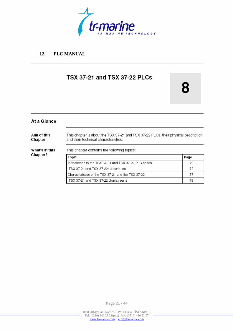
12. PLC MANUAL

Page 22 / 44
Rauf Orbay Cad. No:37/2 34944 Tuzla – İSTANBUL Tel: (0216) 446 23 28(pbx) Fax: (0216) 446 23 27
www.tr-marine.com [email protected]

Page 23 / 44
Rauf Orbay Cad. No:37/2 34944 Tuzla – İSTANBUL Tel: (0216) 446 23 28(pbx) Fax: (0216) 446 23 27
www.tr-marine.com [email protected]

Page 24 / 44
Rauf Orbay Cad. No:37/2 34944 Tuzla – İSTANBUL Tel: (0216) 446 23 28(pbx) Fax: (0216) 446 23 27
www.tr-marine.com [email protected]

Page 25 / 44
Rauf Orbay Cad. No:37/2 34944 Tuzla – İSTANBUL Tel: (0216) 446 23 28(pbx) Fax: (0216) 446 23 27
www.tr-marine.com [email protected]

Page 26 / 44
Rauf Orbay Cad. No:37/2 34944 Tuzla – İSTANBUL Tel: (0216) 446 23 28(pbx) Fax: (0216) 446 23 27
www.tr-marine.com [email protected]

Page 27 / 44
Rauf Orbay Cad. No:37/2 34944 Tuzla – İSTANBUL Tel: (0216) 446 23 28(pbx) Fax: (0216) 446 23 27
www.tr-marine.com [email protected]

Page 28 / 44
Rauf Orbay Cad. No:37/2 34944 Tuzla – İSTANBUL Tel: (0216) 446 23 28(pbx) Fax: (0216) 446 23 27
www.tr-marine.com [email protected]

Page 29 / 44
Rauf Orbay Cad. No:37/2 34944 Tuzla – İSTANBUL Tel: (0216) 446 23 28(pbx) Fax: (0216) 446 23 27
www.tr-marine.com [email protected]

Page 30 / 44
Rauf Orbay Cad. No:37/2 34944 Tuzla – İSTANBUL Tel: (0216) 446 23 28(pbx) Fax: (0216) 446 23 27
www.tr-marine.com [email protected]

Page 31 / 44
Rauf Orbay Cad. No:37/2 34944 Tuzla – İSTANBUL Tel: (0216) 446 23 28(pbx) Fax: (0216) 446 23 27
www.tr-marine.com [email protected]

Page 32 / 44
Rauf Orbay Cad. No:37/2 34944 Tuzla – İSTANBUL Tel: (0216) 446 23 28(pbx) Fax: (0216) 446 23 27
www.tr-marine.com [email protected]

Page 33 / 44
Rauf Orbay Cad. No:37/2 34944 Tuzla – İSTANBUL Tel: (0216) 446 23 28(pbx) Fax: (0216) 446 23 27
www.tr-marine.com [email protected]

Page 34 / 44
Rauf Orbay Cad. No:37/2 34944 Tuzla – İSTANBUL Tel: (0216) 446 23 28(pbx) Fax: (0216) 446 23 27
www.tr-marine.com [email protected]

Page 35 / 44
Rauf Orbay Cad. No:37/2 34944 Tuzla – İSTANBUL Tel: (0216) 446 23 28(pbx) Fax: (0216) 446 23 27
www.tr-marine.com [email protected]

Page 36 / 44
Rauf Orbay Cad. No:37/2 34944 Tuzla – İSTANBUL Tel: (0216) 446 23 28(pbx) Fax: (0216) 446 23 27
www.tr-marine.com [email protected]

Page 37 / 44
Rauf Orbay Cad. No:37/2 34944 Tuzla – İSTANBUL Tel: (0216) 446 23 28(pbx) Fax: (0216) 446 23 27
www.tr-marine.com [email protected]

Page 38 / 44
Rauf Orbay Cad. No:37/2 34944 Tuzla – İSTANBUL Tel: (0216) 446 23 28(pbx) Fax: (0216) 446 23 27
www.tr-marine.com [email protected]

Page 39 / 44
Rauf Orbay Cad. No:37/2 34944 Tuzla – İSTANBUL Tel: (0216) 446 23 28(pbx) Fax: (0216) 446 23 27
www.tr-marine.com [email protected]

Page 40 / 44
Rauf Orbay Cad. No:37/2 34944 Tuzla – İSTANBUL Tel: (0216) 446 23 28(pbx) Fax: (0216) 446 23 27
www.tr-marine.com [email protected]

Page 41 / 44
Rauf Orbay Cad. No:37/2 34944 Tuzla – İSTANBUL Tel: (0216) 446 23 28(pbx) Fax: (0216) 446 23 27
www.tr-marine.com [email protected]

Page 42 / 44
Rauf Orbay Cad. No:37/2 34944 Tuzla – İSTANBUL Tel: (0216) 446 23 28(pbx) Fax: (0216) 446 23 27
www.tr-marine.com [email protected]

Page 43 / 44
Rauf Orbay Cad. No:37/2 34944 Tuzla – İSTANBUL Tel: (0216) 446 23 28(pbx) Fax: (0216) 446 23 27
www.tr-marine.com [email protected]

Page 44 / 44
Rauf Orbay Cad. No:37/2 34944 Tuzla – İSTANBUL Tel: (0216) 446 23 28(pbx) Fax: (0216) 446 23 27
www.tr-marine.com [email protected]