Embed Size (px)
Citation preview

www.furuno.co.jp
FI-504 MULTIFI-507 MULTI XL�Instrument
All brand and product names are trademarks, registered trademarks or service marks of their respective holders.

The paper used in this manual
is elemental chlorine free.
・FURUNO Authorized Distributor/Dealer
9-52 Ashihara-cho,
Nishinomiya, 662-8580, JAPAN
Telephone : +81-(0)798-65-2111
Fax : +81-(0)798-65-4200
A : OCT 2007.Printed in JapanAll rights reserved.
D : JAN . 26, 2011
Pub. No. OME-72690-D
*00016733413**00016733413*(DAMI ) FI-504/507*00016733413**00016733413*
* 0 0 0 1 6 7 3 3 4 1 3 *

i
IMPORTANT NOTICES
General• This manual has been authored with simplified grammar, to meet the needs of international us-
ers.• The operator of this equipment must read and follow the descriptions in this manual. Wrong op-
eration or maintenance can cancel the warranty or cause injury.• Do not copy any part of this manual without written permission from FURUNO.• If this manual is lost or worn, contact your dealer about replacement.• The contents of this manual and equipment specifications can change without notice.• The example screens (or illustrations) shown in this manual can be different from the screens
you see on your display. The screens you see depend on your system configuration and equip-ment settings.
• Save this manual for future reference.• Any modification of the equipment (including software) by persons not authorized by FURUNO
will cancel the warranty.• All brand and product names are trademarks, registered trademarks or service marks of their
respective holders.
How to discard this productDiscard this product according to local regulations for the disposal of industrial waste. For disposal in the USA, see the homepage of the Electronics Industries Alliance (http://www.eiae.org/) for the correct method of disposal.
How to discard a used batterySome FURUNO products have a battery(ies). To see if your product has a battery, see the chapter on Maintenance. Follow the instructions below if a battery is used. Tape the + and - terminals of battery before disposal to prevent fire, heat generation caused by short circuit.
In the European Union
The crossed-out trash can symbol indicates that all types of batteries must not be discarded in standard trash, or at a trash site. Take the used batteries to a battery collection site according to your national legislation and the Batteries Directive 2006/66/EU.
In the USA
The Mobius loop symbol (three chasing arrows) indicates that Ni-Cd and lead-acid rechargeable batteries must be recycled. Take the used batteries to a battery collection site according to local laws.
In the other countries
There are no international standards for the battery recycle symbol. The number of symbols can increase when the other countries make their own recycle symbols in the future.
Cd
Ni-Cd Pb

SAFETY INSTRUCTIONS
ii
WARNING Indicates a potentially hazardous situation which, if not avoided, could result in death or serious injury.
CAUTION Indicates a potentially hazardous situation which, if not avoided, may result in minor or moderate injury.
Warning, Caution Mandatory Action Prohibitive Action
SAFETY INSTRUCTIONSThe operator of this equipment must read these safety instructions before attempting tooperate the equipment.
WARNINGDo not open the equipment.
Only qualified personnel should work inside the equipment.
Do not disassemble or modifythe equipment.
Fire or electrical shock can result ifthe equipment is modified.
Do not operate the equipmentwith wet hands.
Electrical shock can result.
Safety instructions for the operator
Make sure no rain or water splash leaks into the equipment.
Fire or electrical shock can resultif water leaks into the equipment.
Immediately turn off the powerat the switchboard if water leaksinto the equipment.
Continued use of the equipment can cause fire or electrical shock.
Safety instructions for the installer
WARNINGTurn off the power at the switch-board before beginning theinstallation.
Turn off the power to preventelectrical shock.
Make sure the installation site isnot subject to water spray.
Fire or electrical shock can result ifwater leaks into the equipment.
CAUTIONCAUTIONObserve the following compasssafe distances to prevent interfer-ence to the instruments:
Standardcompass
Steeringcompass
0.35 mFI-504FI-507
Warning LabelA warning label is attached to the equipment. Do notremove the label. If the label is missing or damaged,contact a FURUNO agent or dealer about replacement.
0.30 m0.25 m

iii
TABLE OF CONTENTS
FOREWORD.............................................................................................. ivSYSTEM CONFIGURATION ....................................................................... v
1.OPERATION............................................................................................. 11.1 Operating Controls, Display Layout...................................................................... 11.2 Turning the Power On/Off .................................................................................... 21.3 Adjusting Brilliance and Contrast ......................................................................... 21.4 Selecting a Display............................................................................................... 31.5 Selecting Apparent or True Wind Angle, Wind Speed.......................................... 81.6 Resetting Counters and Indications ..................................................................... 81.7 Alarms .................................................................................................................. 91.8 Timers ................................................................................................................ 11
2. MAINTENANCE, TROUBLESHOOTING .............................................. 132.1 Preventive Maintenance..................................................................................... 132.2 Troubleshooting.................................................................................................. 14
3. INSTALLATION..................................................................................... 153.1 Equipment Lists.................................................................................................. 153.2 Mounting............................................................................................................. 163.3 Wiring ................................................................................................................. 183.4 Setting Up........................................................................................................... 21
SPECIFICATIONS .................................................................................SP-1PACKING LIST........................................................................................ A-1OUTLINE DRAWINGS............................................................................. D-1INTERCONNECTION DIAGRAM ............................................................ S-1

iv
FOREWORD
A Word to the Owner of the FI-504, FI-507Congratulations on your choice of the FURUNO FI-504 Multi/FI-507 Multi XL displays, members of the FI-50 series of marine instruments. We are confident you will see why the FURUNO name has become synonymous with quality and reliability.
For over 60 years FURUNO Electric Company has enjoyed an enviable reputation for quality marine electronics equipment. This dedication to excellence is furthered by our extensive global network of agents and dealers.
This equipment is designed and constructed to meet the rigorous de-mands of the marine environment. However, no machine can perform its intended function unless operated and maintained properly. Please care-fully read and follow the recommended procedures for operation and maintenance.
Thank you for considering and purchasing FURUNO equipment.
FeaturesThe FI-504 Multi/FI-507 Multi XL displays provide heading, environment, autopilot, engine, depth, speed, and wind information, all on a high qual-ity, backlit LCD. The sturdy weather-proof case is built to stand up to even the harshest of environments.
The main features are
• Eight varieties of displays: heading, environment, autopilot, engine, depth, speed, timer, and wind.
• Four levels of backlighting including off.• Timers: Stopwatch and count-down• Depth alarms: Shallow alarm, Deep alarm• Anchor alarms: Shallow alarm, Deep alarm• Voltage alarm monitors power source voltage• Wind alarms: High apparent wind angle, Low apparent wind angle,
Max. true wind speed, Low true wind speed• Speed indications: Max. STW, Average STW, SOG, Max. SOG, Aver-
age SOG, Wind speed, Max. true wind speed• Log indication from 0 to 99,999 nm• Resettable trip counter, from 0 to 999 nm
v
SYSTEM CONFIGURATION
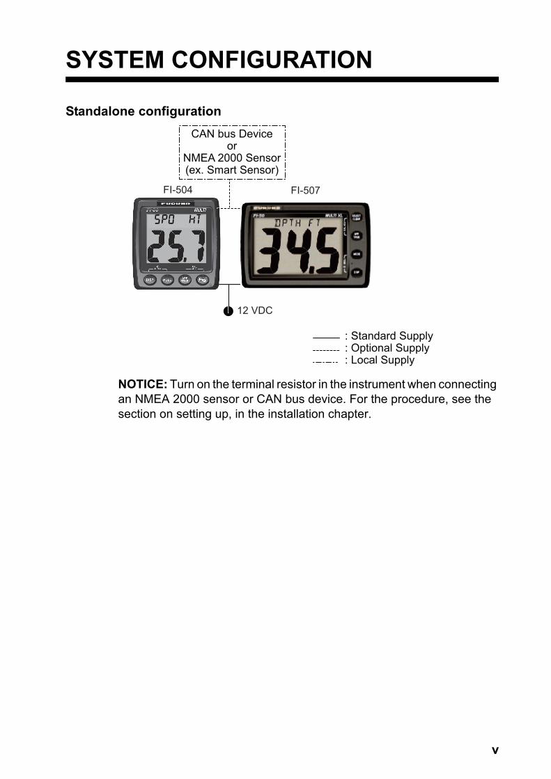
Standalone configuration
NOTICE: Turn on the terminal resistor in the instrument when connecting an NMEA 2000 sensor or CAN bus device. For the procedure, see the section on setting up, in the installation chapter.
: Standard Supply: Optional Supply: Local Supply
12 VDC
CAN bus Deviceor
NMEA 2000 Sensor(ex. Smart Sensor)
FI-504 FI-507

SYSTEM CONFIGURATION
vi
CAN bus network
NOTICE: Turn on the terminal resistor in the terminator of the CAN bus network.
FI-501*and/orFI-502
FI-5001 orFI-5001L
WINDTRANSDUCERTERMINAL BOX
(where necessary)
FI-503DIGITAL
FI-504 MULTI
FI-505COURSE PILOT
FI-506RUDDER
30
: Standard Supply: Optional Supply: Local Supply
*FI-501 Wind Angle FI-502 Close Hauled Wind Angle
JUNCTION BOXFI-5002
* NMEA 2000 SENSORS - Boat speed - Depth - Heading - Navigation - Environment - Autopilot - Engine
12 VDC(not necessary if poweredby CAN bus network)
CAN busDevice
or NMEA 2000SENSOR*
CAN busDevice
or NMEA 2000SENSOR*
CAN busDevice
or NMEA 2000SENSOR*
CAN busDevice
or NMEA 2000SENSOR*
CAN busDevice
or NMEA 2000SENSOR*
FI-507 MULTI XL
1
1. OPERATION
Provided applicable sensors are connected, the FI-504/FI-507 provides the following information, all on a backlit LCD:
• Depth• Speed• Heading• Environment data• Autopilot (rudder)• Engine• Wind• Timers• Navigation data
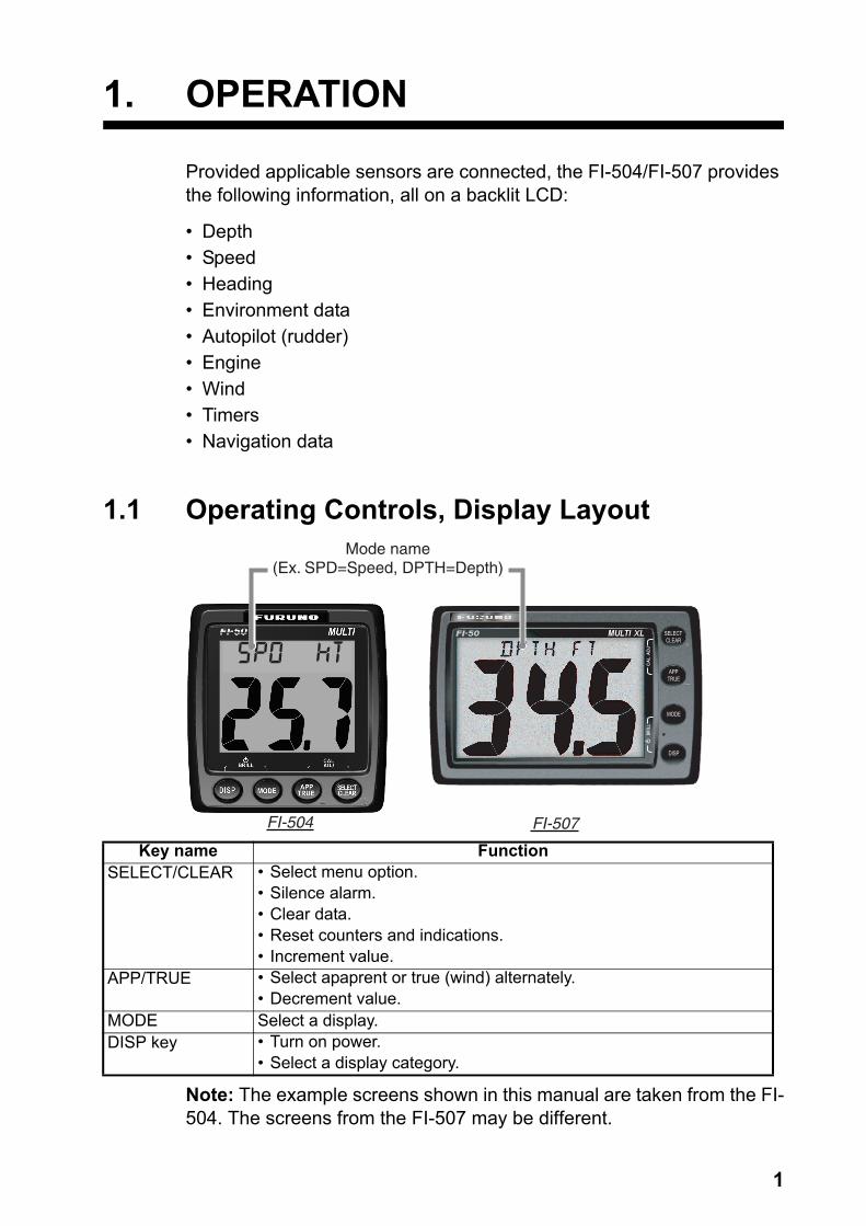
1.1 Operating Controls, Display Layout
Note: The example screens shown in this manual are taken from the FI-504. The screens from the FI-507 may be different.
Key name FunctionSELECT/CLEAR • Select menu option.
• Silence alarm.• Clear data.• Reset counters and indications.• Increment value.
APP/TRUE • Select apaprent or true (wind) alternately.• Decrement value.
MODE Select a display.DISP key • Turn on power.
• Select a display category.
DISP
MODE
APPTRUE
SELECTCLEAR
FI-507
Mode name(Ex. SPD=Speed, DPTH=Depth)
FI-504
1. OPERATION
2
1.2 Turning the Power On/OffTo power the instrument, press the DISP key. All LCD segments go on and off and then the last-used display appears.
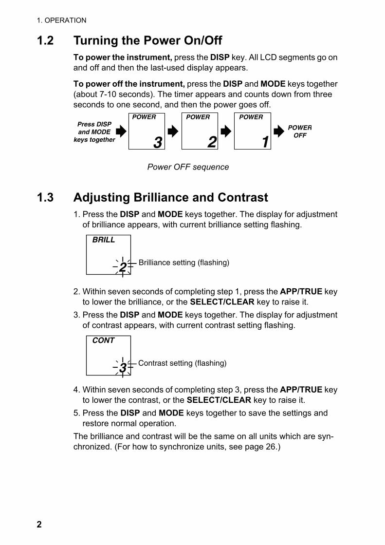
To power off the instrument, press the DISP and MODE keys together (about 7-10 seconds). The timer appears and counts down from three seconds to one second, and then the power goes off.
Power OFF sequence
1.3 Adjusting Brilliance and Contrast1. Press the DISP and MODE keys together. The display for adjustment
of brilliance appears, with current brilliance setting flashing.
2. Within seven seconds of completing step 1, press the APP/TRUE key to lower the brilliance, or the SELECT/CLEAR key to raise it.
3. Press the DISP and MODE keys together. The display for adjustment of contrast appears, with current contrast setting flashing.
4. Within seven seconds of completing step 3, press the APP/TRUE key to lower the contrast, or the SELECT/CLEAR key to raise it.
5. Press the DISP and MODE keys together to save the settings and restore normal operation.
The brilliance and contrast will be the same on all units which are syn-chronized. (For how to synchronize units, see page 26.)
POWEROFF
Press DISPand MODE
keys together 3
POWER
2 1
POWER POWER
Brilliance setting (flashing) 2
BRILL
Contrast setting (flashing) 3
CONT
1. OPERATION
3
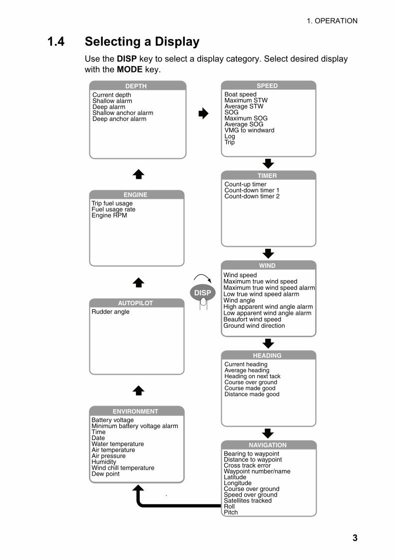
1.4 Selecting a DisplayUse the DISP key to select a display category. Select desired display with the MODE key.
HEADINGCurrent headingAverage headingHeading on next tackCourse over groundCourse made goodDistance made good
NAVIGATIONBearing to waypointDistance to waypointCross track errorWaypoint number/nameLatitudeLongitudeCourse over groundSpeed over groundSatellites trackedRollPitch
AUTOPILOTRudder angle
ENGINETrip fuel usageFuel usage rateEngine RPM
SPEEDBoat speedMaximum STWAverage STWSOGMaximum SOGAverage SOGVMG to windwardLogTrip
TIMERCount-up timerCount-down timer 1Count-down timer 2
DEPTHCurrent depthShallow alarmDeep alarmShallow anchor alarmDeep anchor alarm
WIND
Wind speedMaximum true wind speedMaximum true wind speed alarmLow true wind speed alarmWind angleHigh apparent wind angle alarmLow apparent wind angle alarmBeaufort wind speedGround wind direction
ENVIRONMENTBattery voltageMinimum battery voltage alarmTimeDateWater temperatureAir temperatureAir pressureHumidityWind chill temperatureDew point
DISP
1. OPERATION
4
1.4.1 Display description
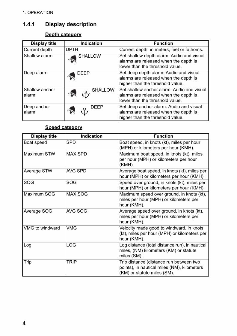
Depth category
Speed category
Display title Indication FunctionCurrent depth DPTH Current depth, in meters, feet or fathoms.Shallow alarm SHALLOW Set shallow depth alarm. Audio and visual
alarms are released when the depth is lower than the threshold value.
Deep alarm DEEP Set deep depth alarm. Audio and visual alarms are released when the depth is higher than the threshold value.
Shallow anchor alarm
SHALLOW Set shallow anchor alarm. Audio and visual alarms are released when the depth is lower than the threshold value.
Deep anchoralarm
DEEP Set deep anchor alarm. Audio and visual alarms are released when the depth is higher than the threshold value.
Display title Indication FunctionBoat speed SPD Boat speed, in knots (kt), miles per hour
(MPH) or kilometers per hour (KMH).Maximum STW MAX SPD Maximum boat speed, in knots (kt), miles
per hour (MPH) or kilometers per hour (KMH).
Average STW AVG SPD Average boat speed, in knots (kt), miles per hour (MPH) or kilometers per hour (KMH).
SOG SOG Speed over ground, in knots (kt), miles per hour (MPH) or kilometers per hour (KMH).
Maximum SOG MAX SOG Maximum speed over ground, in knots (kt), miles per hour (MPH) or kilometers per hour (KMH).
Average SOG AVG SOG Average speed over ground, in knots (kt), miles per hour (MPH) or kilometers per hour (KMH).
VMG to windward VMG Velocity made good to windward, in knots (kt), miles per hour (MPH) or kilometers per hour (KMH).
Log LOG Log distance (total distance run), in nautical miles, (NM) kilometers (KM) or statute miles (SM).
Trip TRIP Trip distance (distance run between two points), in nautical miles (NM), kilometers (KM) or statute miles (SM).

1. OPERATION
5
Timer category
Wind category
Beaufort no. and wind speed
Display title Indication FunctionCount up timer UP Count-up timer.Count down timer 1 DOWN 1 Count-down timer 1.Count down timer DOWN 2 Count-down timer 2.
Display title Indication FunctionWind speed APP (or TRUE) Wind speed, in knots or meters/second. Maximum true wind speed
MAX TRUE Maximum true wind speed.
Maximum true wind speed alarm
MAX TRUE Set maximum true wind speed alarm. Audio and visual alarms are released when the wind speed goes higher than the threshold value.
Low true wind speed alarm
TRUE LO Set low true wind speed alarm. Audio and visual alarms are released when the wind speed goes lower than the threshold value.
Wind angle APP (or TRUE) Apparent (or true) wind angle, in degrees.High apparent wind angle alarm
APP HI Set high apparent wind angle alarm. Audio and visual alarms are released when the wind angle at starboard goes higher than the threshold value.
Low apparent wind angle alarm
APP LO Set low apparent wind angle alarm. Audio and visual alarms are released when the wind angle at port goes lower than the threshold value.
Beaufort wind speed
BFT Beaufort wind speed. Beaufort speeds up to 12 are shown. See the table below for Beau-fort no. and wind speed.
Ground wind angle GWIND Angle of wind over ground, in degrees. Bearing reference in Magnetic (MAG) or True (TRUE).
Beaufortno.
Wind speed Beaufortno.
Wind speed
kt m/s kt m/s0 0 0-0.2 7 28-33 14.4-17.41 1-3 0.5-2.0 8 34-40 17.5-21.02 4-6 2.1-3.5 9 41-47 21.1-24.63 7-10 3.6-5.6 10 48-55 24.7-28.84 11-16 5.7-8.6 11 56-63 28.9-32.65 17-21 8.7-11.2 12 64 32.7-32.96 22-27 11.3-14.3

1. OPERATION
6
Heading category
Navigation category
Display title Indication FunctionCurrent heading HDG Heading, in degrees. Bearing reference
in Magnetic (MAG) or True (TRUE).Average heading AVG HDG Average heading, in degrees. Bearing
reference in Magnetic (MAG) or True (TRUE).
Heading on next tack TACK Heading on next tack, in degrees true (fixed). Bearing reference in Magnetic (MAG) or True (TRUE).
Course over ground COG Course over ground, in degrees. Bear-ing reference in Magnetic (MAG) or True (TRUE).
Course made good CMG Course made good, in degrees. Bearing reference in Magnetic (MAG) or True (TRUE).
Distance made good DMG Distance made good, in kilometers (km), nautical miles (nm) or statute miles (sm).
Display title Indication FunctionBearing to waypoint BTW Bearing to waypoint, in degrees.
Bearing reference of Magnetic (MAG) or True (TRUE)
Distance to waypoint DTW Distance to waypoint, in kilometers (KM), nautical miles (NM) or statute miles (SM).
Cross track error XTE Cross-track error, in kilometers (KM), nautical miles (NM) or statute miles (SM).
Waypoint number/name WPT Waypoint number and name are shown.Latitude LAT Position in latitude.Longitude LON Position in longitude.Course over ground COG Course over ground, in degrees.
Bearing reference in Magnetic (MAG) or True (TRUE).
Speed over ground SOG Speed over ground, in knots (KT), miles per hour (MPH) or kilometers per hour (KMH).
Satellites tracked GPS SAT GPS satellites tracked.Roll ROLL Ship’s roll, in degrees.Pitch PITCH Ship’s pitch, in degrees.
1. OPERATION
7
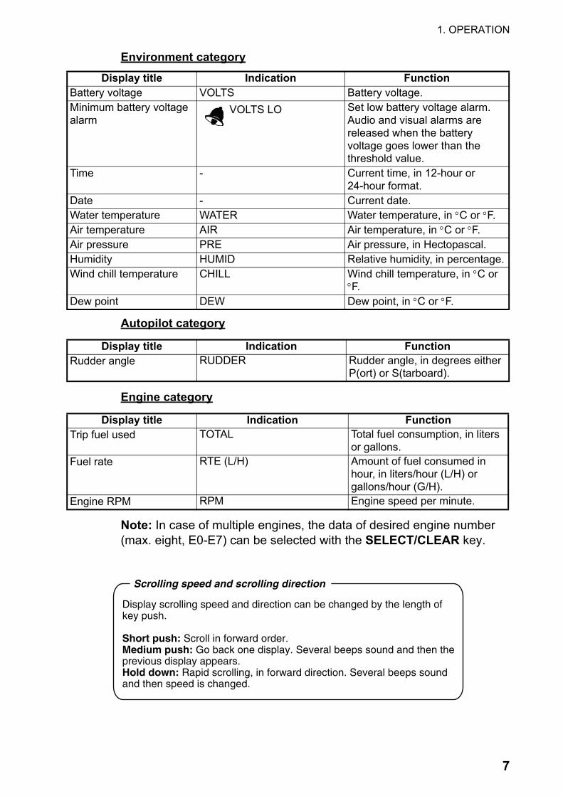
Environment category
Autopilot category
Engine category
Note: In case of multiple engines, the data of desired engine number (max. eight, E0-E7) can be selected with the SELECT/CLEAR key.
Display title Indication FunctionBattery voltage VOLTS Battery voltage.Minimum battery voltage alarm
VOLTS LO Set low battery voltage alarm. Audio and visual alarms are released when the batteryvoltage goes lower than the threshold value.
Time - Current time, in 12-hour or24-hour format.
Date - Current date.Water temperature WATER Water temperature, in °C or °F.Air temperature AIR Air temperature, in °C or °F.Air pressure PRE Air pressure, in Hectopascal.Humidity HUMID Relative humidity, in percentage.Wind chill temperature CHILL Wind chill temperature, in °C or
°F.Dew point DEW Dew point, in °C or °F.
Display title Indication FunctionRudder angle RUDDER Rudder angle, in degrees either
P(ort) or S(tarboard).
Display title Indication FunctionTrip fuel used TOTAL Total fuel consumption, in liters
or gallons.Fuel rate RTE (L/H) Amount of fuel consumed in
hour, in liters/hour (L/H) orgallons/hour (G/H).
Engine RPM RPM Engine speed per minute.
Display scrolling speed and direction can be changed by the length of key push.
Short push: Scroll in forward order.Medium push: Go back one display. Several beeps sound and then the previous display appears.Hold down: Rapid scrolling, in forward direction. Several beeps soundand then speed is changed.
Scrolling speed and scrolling direction

1. OPERATION
8
1.5 Selecting Apparent or True Wind Angle,Wind SpeedYou can show wind angle and wind speed in apparent or true wind. The apparent wind is the actual flow of air acting upon a sail, or the wind as it appears to the sailor. True wind is the wind seen by a stationary ob-server in velocity and direction.
WIth a wind angle or wind speed indication displayed, press the APP/TRUE key to change the wind angle or wind speed to apparent and true alternately. A beep sounds after the change is completed. (Wind angle and wind speed displays are mutually changed.) True wind requires boat speed input. If there is no speed input three dashes appear.
1.6 Resetting Counters and IndicationsYou can reset the following counters and indications:
• Trip• Course made good• Distance made good• Average speed• Average SOG• Maximum speed• Maximum SOG• Average heading• Maximum true wind speed
Select the applicable display and press and hold down the SELECT/CLEAR key. A short beep sounds, the counter or indication flashes twice and then a long beep sounds to indicate that resetting is completed.
HI
APP KT
5.0
HI
TRUE KT
APPTRUE
Apparent and truewind speeds
Apparent and truewind angles
HI
APP
HI
TRUE
APPTRUE
135
157 9.6
1. OPERATION
9
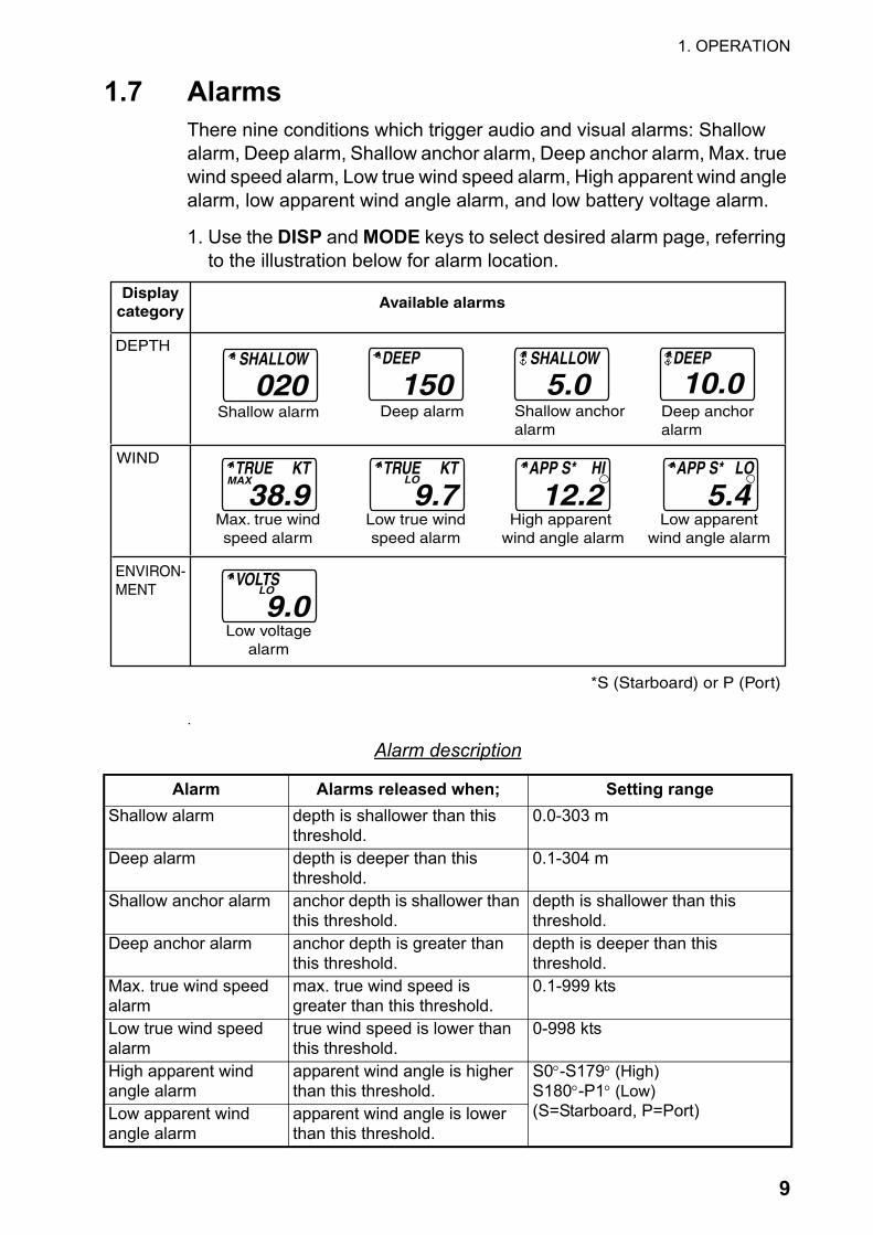
1.7 AlarmsThere nine conditions which trigger audio and visual alarms: Shallow alarm, Deep alarm, Shallow anchor alarm, Deep anchor alarm, Max. true wind speed alarm, Low true wind speed alarm, High apparent wind angle alarm, low apparent wind angle alarm, and low battery voltage alarm.
1. Use the DISP and MODE keys to select desired alarm page, referring to the illustration below for alarm location.
.
Alarm description
Alarm Alarms released when; Setting rangeShallow alarm depth is shallower than this
threshold.0.0-303 m
Deep alarm depth is deeper than this threshold.
0.1-304 m
Shallow anchor alarm anchor depth is shallower than this threshold.
depth is shallower than thisthreshold.
Deep anchor alarm anchor depth is greater than this threshold.
depth is deeper than thisthreshold.
Max. true wind speed alarm
max. true wind speed is greater than this threshold.
0.1-999 kts
Low true wind speed alarm
true wind speed is lower than this threshold.
0-998 kts
High apparent wind angle alarm
apparent wind angle is higher than this threshold.
S0°-S179° (High)S180°-P1° (Low)(S=Starboard, P=Port)Low apparent wind
angle alarmapparent wind angle is lower than this threshold.
Displaycategory
DEPTH
WIND
Available alarms
SHALLOW
020Shallow alarm Deep alarm
DEEP
150 SHALLOW
5.0Shallow anchoralarm
Deep anchoralarm
DEEP
10.0
Max. true windspeed alarm
TRUE KT
38.9MAX
Low true windspeed alarm
TRUE KT
9.7LO
High apparent wind angle alarm
APP S* HI
12.2Low apparent
wind angle alarm
APP S* LO
5.4
ENVIRON-MENT
Low voltagealarm
VOLTS
9.0LO
*S (Starboard) or P (Port)

1. OPERATION
10
2. If the selected alarm page shows “Off,” press and hold down the SELECT/CLEAR key until an alarm setting appears.
3. Press the APP/TRUE and SELECT/CLEAR keys together to enable adjustment. The alarm setting starts flashing.
4. Press the APP/TRUE key to lower the setting; the SELECT/CLEAR key to raise it. Note: A low alarm cannot be set higher than its affiliated high (max.) alarm.
5. Press the APP/TRUE and SELECT/CLEAR keys together to confirm setting and restore normal operation.
When an alarm is violated, the buzzer sounds and the alarm icon ( ) flashes. You can silence the buzzer with the SELECT/CLEAR key. The icon continues flashing until the offending alarm is disabled.
While the icon is flashing you can switch between alarm display and cur-rent display alternately by pressing the DISP and SELECT/CLEAR keys together.
Low battery voltage alarm
battery voltage is lower than this threshold.
5.0 - 20.0 volts
Alarm description
Alarm Alarms released when; Setting range

1. OPERATION
11
1.8 TimersThree timers are provided:
• Count-up timer (stopwatch)• Count-down timer (two provided)
Time is displayed in seconds or minutes, depending on counter values.
Once you have set a timer, you can leave that page and select any other display. The counter continues to run in the background.
Count-up timer
The count-up timer functions like a stop watch, counting time upward, to 99 hours, 99 minutes and 59 seconds.
Count-down timers
The two count-down timers count down from a time between 15 minutes and one minute. When these timers have counted down to zero, they then start counting up. The timers beep at preset intervals to alert you to specific points in time.
• Two beeps every minute• Three beeps at the start of the last 30 seconds• One beep/second for each of the last 10 seconds• Two-second beep at zero
How to set the timers
1. Press the MODE key to show the desired timer display.
2. Do one of the following depending on timer type selected:Count-up timer:Press the SELECT/CLEAR key to start the timer. A long beep sounds and the timer starts counting upward.
Count-down timer:To start the timer from the time shown, press the SELECT/CLEAR key. To set a different start time, press the APP/TRUE and SELECT/CLEAR keys together to enable adjustment. Use the APP/TRUE key to lower the value; SELECT/CLEAR key to raise it. Press the APP/TRUE and SELECT/CLEAR keys together to confirm setting. Press the SELECT/CLEAR key to start the timer.
Count-uptimer
00:00:00.0
UPCount-down
timer 1
DOWN 1
15.0Count-down
timer 2
DOWN 2
15.0
1. OPERATION
12
To stop or restart the timer, press the SELECT/CLEAR key momen-tarily. A short beep sounds when the timer is stopped or restarted.
To stop and reset the timer to start value, press the SELECT/CLEAR key until you hear a long beep. The timer is stopped and reset to start value.
The timer settings are reflected on any timer-equipped instrument in the network which is set up for synchronization.

13
2. MAINTENANCE,TROUBLESHOOTING
This chapter provides the information necessary for keeping your equip-ment in good working order.
2.1 Preventive MaintenanceFollowing the recommended procedures below will help maintain perfor-mance.
Check item Check point Remedy
Cabling Check that all cabling is securely fastened and is free or rust and corrosion.
Reconnect if necessary. Replace if damaged.
Cabinet Dust on cabinet Remove dust with a soft, lint-free cloth.
WARNINGDo not open the equipment.
Only qualified personnel should work inside the equipment.
NOTICEDo not apply paint, anti-corrosivesealant or contact spray to coatingor plastic parts of the equipment.
Those items contain organic solventsthat can damage coating and plasticparts, especially plastic connectors.

2. MAINTENANCE, TROUBLESHOOTING
14
2.2 TroubleshootingIf you feel the equipment is not functioning properly, follow the proce-dures in the table below to try to restore normal operation. If normal op-eration cannot be restored, do not attempt to check inside the cabinet. There are no user-serviceable parts inside.
Troubleshooting
Problem Possible cause RemedyDisplay is blank. Panel is not lit.
• Power supply• Cabling disconnected or
damaged.
• Check power supply.• Check cabling.
Power is on but no or some data.
Sensor is turned off.Cable from sensor is disconnected or damaged.
• Turn on sensor.• Check cabling.
Inaccurate data • Electromagnetic field generating equipment is in operation.
• Cabling from sensor is damaged.
• Sensor is improperly aligned (where applicable).
• Turn off all electromagnetic field generating equipment. Turn them on and off one by one. Check the dis-play. Relocate offending equipment or this instrument as appropriate.
• Check cabling.
• Check installation. If installation is proper, an offset may be applied to certain data. For details, see section 1.7.
15
3. INSTALLATION
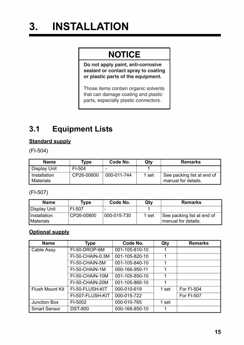
3.1 Equipment ListsStandard supply
(FI-504)
(FI-507)
Optional supply
Name Type Code No. Qty RemarksDisplay Unit FI-504 - 1InstallationMaterials
CP26-00600 000-011-744 1 set See packing list at end ofmanual for details.
Name Type Code No. Qty RemarksDisplay Unit FI-507 - 1InstallationMaterials
CP26-00800 000-015-730 1 set See packing list at end ofmanual for details.
Name Type Code No. Qty RemarksCable Assy. FI-50-DROP-6M 001-105-810-10 1
FI-50-CHAIN-0.3M 001-105-820-10 1FI-50-CHAIN-5M 001-105-840-10 1FI-50-CHAIN-1M 000-166-950-11 1FI-50-CHAIN-10M 001-105-850-10 1FI-50-CHAIN-20M 001-105-860-10 1
Flush Mount Kit FI-50-FLUSH-KIT 000-010-619 1 set For FI-504FI-507-FLUSH-KIT 000-015-722 For FI-507
Junction Box FI-5002 000-010-765 1 setSmart Sensor DST-800 000-168-850-10 1
NOTICEDo not apply paint, anti-corrosivesealant or contact spray to coatingor plastic parts of the equipment.
Those items contain organic solventsthat can damage coating and plasticparts, especially plastic connectors.

3. INSTALLATION
16
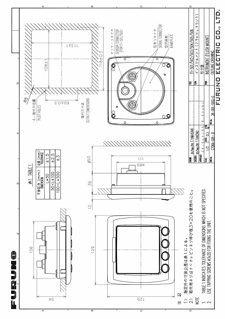
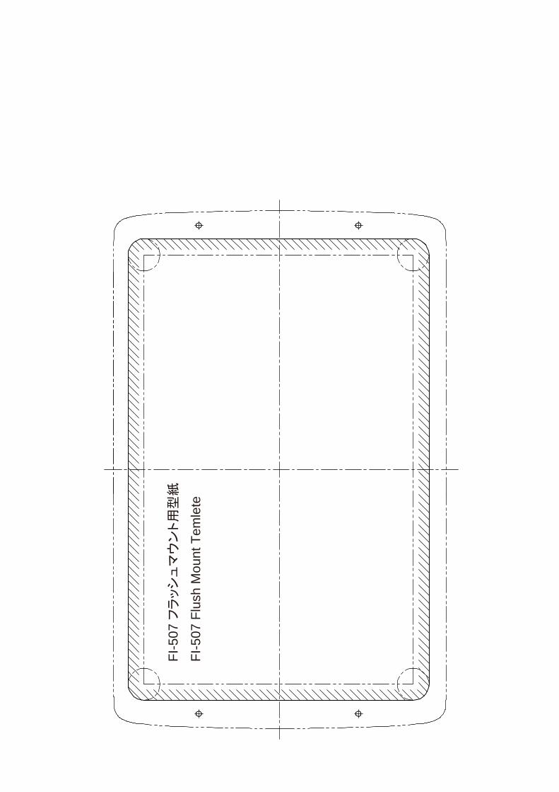
3.2 MountingThe display unit can be installed two ways: surface mount (fixed at front panel or fixed from rear panel) and flush mount (optional kit required). This section covers surface mounting. For flush mounting, see the flush mounting instructions, issued separately.
Surface mount 1: Fix instrument from front panel
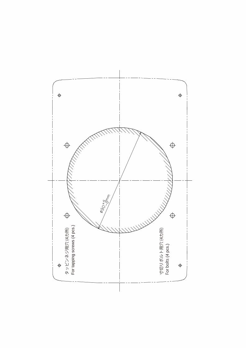
1. Using the applicable template at the back of this manual, open a mounting hole in the installation site.
2. Detach the front panel together with the keypad assy. Attach sponge (supplied) to rear of display unit.
3. Set the display unit to the mounting hole, and fix it with four self-tap-ping screws (3×20, supplied).
4. Attach the front panel and keypad assy. to the display unit.
Self-tapping screw (3x20)
MountingHole
Front Panel
Keypad Assy.Sponge
(ex. FI-504)
3. INSTALLATION
17
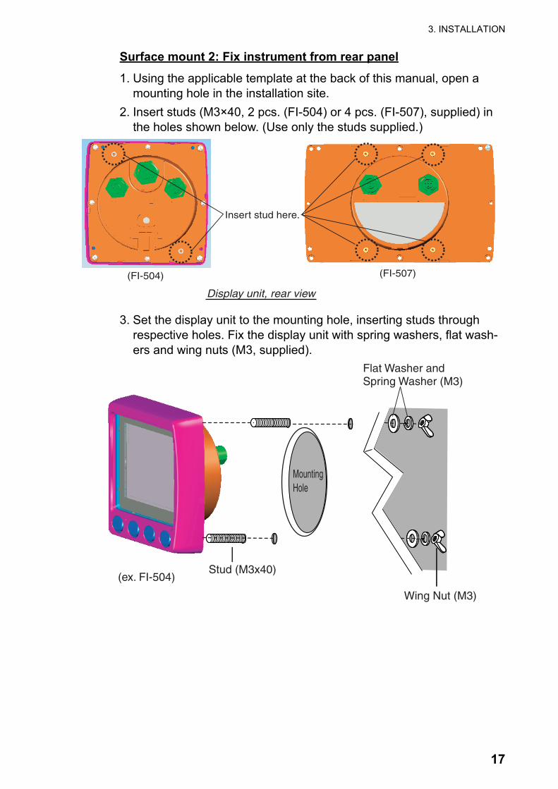
Surface mount 2: Fix instrument from rear panel
1. Using the applicable template at the back of this manual, open a mounting hole in the installation site.
2. Insert studs (M3×40, 2 pcs. (FI-504) or 4 pcs. (FI-507), supplied) in the holes shown below. (Use only the studs supplied.)
3. Set the display unit to the mounting hole, inserting studs through respective holes. Fix the display unit with spring washers, flat wash-ers and wing nuts (M3, supplied).
Insert stud here.
(FI-504) (FI-507)
Display unit, rear view
Stud (M3x40)
Wing Nut (M3)
MountingHole
(ex. FI-504)
Flat Washer and Spring Washer (M3)
3. INSTALLATION
18
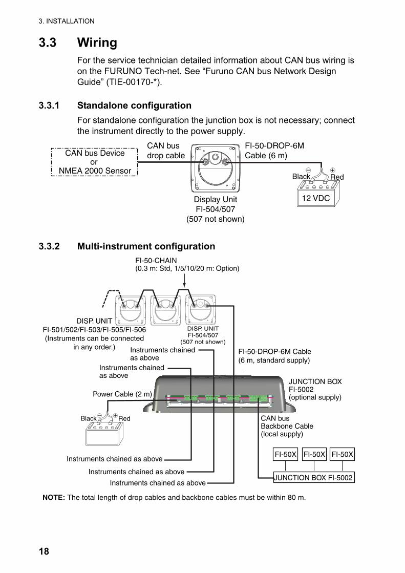
3.3 WiringFor the service technician detailed information about CAN bus wiring is on the FURUNO Tech-net. See “Furuno CAN bus Network Design Guide” (TIE-00170-*).
3.3.1 Standalone configurationFor standalone configuration the junction box is not necessary; connect the instrument directly to the power supply.
3.3.2 Multi-instrument configuration
FI-50-DROP-6MCable (6 m)
Display UnitFI-504/507
(507 not shown)
RedBlack+–
12 VDC
CAN bus Deviceor
NMEA 2000 Sensor
CAN busdrop cable
FI-50-DROP-6M Cable(6 m, standard supply)
RedBlack +–
DISP. UNITFI-504/507
(507 not shown)
DISP. UNITFI-501/502/FI-503/FI-505/FI-506(Instruments can be connected
in any order.)
FI-50-CHAIN(0.3 m: Std, 1/5/10/20 m: Option)
Power Cable (2 m)
CAN busBackbone Cable(local supply)
NOTE: The total length of drop cables and backbone cables must be within 80 m.
JUNCTION BOXFI-5002(optional supply)
Instruments chainedas above
Instruments chainedas above
Instruments chained as above
Instruments chained as above
Instruments chained as aboveJUNCTION BOX FI-5002
FI-50X FI-50XFI-50X

3. INSTALLATION
19
Junction box (option)
The junction box is required when connecting CAN bus network. This section covers wiring of the junction box. For how to mount the junction box, see its installation instructions, issued separately.
CH3 DROP - CH5 DROP and BACKBONE are socket-and-plug-type ter-minal blocks. Detach plug to connect wiring to it, by rocking it back and forth with your fingers. Remove approx. 6 mm of the sheath from the end of wires and twist wires. Loosen fixing screw in the plug, insert wire into hole and tighten fixing screw. Set plug to socket.
12 VDC
CN112VDC
CN3DROP
CN2BACKBONE
FI-501/502/503/504/505/506/507CAN busDevice
Fix cable with cabletie (supplied).
CN4DROP
CN5DROP
Fixing screw
Hole for wire
Wire Twist
How to insert wire
6mm
Sheath
How to fabricate cable
WhiteRedBlueBlack
Drain wire

3. INSTALLATION
20
Terminal resistor
The illustration below show various system configurations and what units to activate the terminal resistor.
= Terminal resistor ON
FI-50xSmartSensor
Smart sensor+FI-50x
FI-50x
Multiple FI-50 series instruments, FI-5002, drop cabling
FI-5002
FI-50x FI-50x FI-50xDrop cable
FI-50x
FI-5002
FI-50x FI-50x FI-50x
Multiple FI-50 series instruments, FI-5002
FI-50x
FI-5002
FI-50x FI-50x
Multiple FI-50 series instruments, FI-5002, smart sensor
SmartSensor
Multiple FI-50 series instruments, multiple FI-5002
FI-5002
FI-50x FI-50x
FI-5002
FI-50x FI-50x
FI-5002
FI-50x FI-50x
Multiple FI-50 series instruments, FI-5002, heading sensor, smart sensor
Multiple FI-50 series instruments, FI-5002, NMEA 2000, CAN bus sensors
FI-5002
FI-50x FI-50x
HeadingSensor(ex. SC-30)
SmartSensor
T-connector T-connectorT-connector
NMEA 2000Sensor
FI-5002
FI-50x FI-50x
CAN bus Deviceor
NMEA 2000 Sensor
T-connector
CAN bus Deviceor
NMEA 2000 Sensor
T-connector
Terminator
Terminator Terminator

3. INSTALLATION
21
Turn on the terminal resistor in the junction box when the FURUNO CAN bus and/or NMEA 2000 sensor(s) connected to it do not have a terminal resistor.
For how to turn on the terminal resistor in a FI-50 series instrument, see paragraph 3.4.2 “Setup2 menu”.
3.4 Setting UpYour instrument is pre-programmed with factory default settings, which may or may not be suited to your vessel. Therefore, it is necessary to ini-tialize the instrument for use with your vessel. This should be done im-mediately after completion of the installation.
Two sets of setup menus are provided: setup1 and setup2. The setup1 menu provides system parameters and the setup2 menu has user set-tings.
3.4.1 Setup1 menuThe setup1 menu contains system parameters which optimize the instru-ment for use on your vessel. Follow the procedure below to access and set parameters.
1. Press the APP/TRUE and SELECT/CLEAR keys momentarily to enable the setup1 menu. The Depth unit selection screen appears, with the depth unit flashing. (See the illustration on the next page.)
2. Use the DISP key to select a menu item. Each press of the key changes the menu item in the sequence shown in the illustration on the next page.
Terminal ResistorOFF:ON:

3. INSTALLATION
22
.
3. Use the APP/TRUE or SELECT/CLEAR key to set value or select option.VMG key: Decrement valueSELECT/CLEAR key: Increment value or select option.
4. To continue, press the DISP key to select another menu item.5. To save settings and restore normal operation, press the APP/TRUE
and SELECT/CLEAR keys together.
Depth unit
DPTH MCAL
Shallow alarm lock
SHWLOCKCAL
OffDepth response
DPT RESCAL
3Speed unit
SPD KTCAL
Speed unit resolution
SPD CAL
0.01Speed offset
SPD --- --- ---
1.00 Speed response
SPD RESCAL
0
VMG response
VMG RESCAL
3Audio alarmenable/disable
TIMER CAL
On Wind data selection
WIND CAL
F Wind unit
WIND KT CAL
Wind speedadjustment
WINDADJ CAL
1.0
Wind angle offset
ANGLE S CAL
0Wind speedresponse
WSPDRES CAL
3 Heading reference
HDG MAG CAL
Heading response
HDG RESCAL
0 Heading lock
HDGLOCK CAL
LOC
Depth offset
DPTH M
0.0CAL
LOG unit
LOG NM
SOG response
SOG RESCAL
0
TIME HR --- ---:--- --- TEMP C W TEMP FUEL L
Time format
CAL
12 Local time
CAL
0 Water temp. unit
CAL
Water temp. offset
CAL
0.0 Fuel unit
CAL
CAL CAL

3. INSTALLATION
23
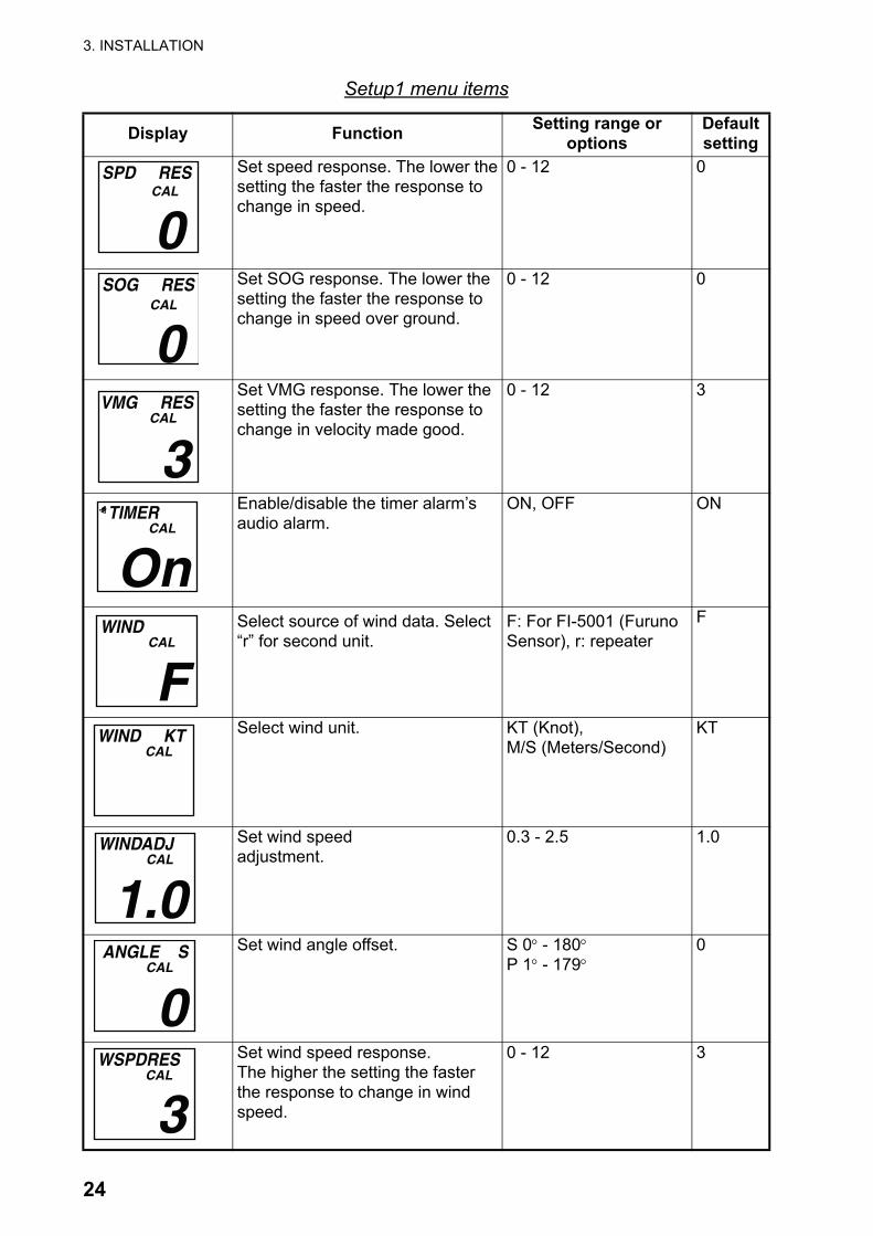
Setup1 menu items
Display Function Setting range or options
Defaultsetting
Select depth unit. M (Meter),FT (Feet)
M
Set depth offset. -99 - +99 0.0
Lock/unlock shallow alarm setting. ON, OFF OFF
Set depth response. The lower thesetting the faster the response to change in depth.
0 - 12 3
Select speed unit. KT (Knot),MPH (Miles/Hour),KMH (Kilometers/Hour)
KT
Select speed resolution. Select number of places to show after decimal point.
0.01, 0.1 0.01
Set speed adjustment.(STW only)
0.30 - 2.50 1.00
Select log unit. NM (Nautical Mile),SM (Statute Mile),KM (Kilometer)
NM
DPTH MCAL
DPTH M
0.0CAL
SHWLOCKCAL
OFF DPT RES
CAL
3 SPD KT
CAL
SPD CAL
0.01 SPD --- --- ---
1.00CAL
LOG NMCAL
3. INSTALLATION
24
Set speed response. The lower thesetting the faster the response to change in speed.
0 - 12 0
Set SOG response. The lower thesetting the faster the response to change in speed over ground.
0 - 12 0
Set VMG response. The lower thesetting the faster the response to change in velocity made good.
0 - 12 3
Enable/disable the timer alarm’s audio alarm.
ON, OFF ON
Select source of wind data. Select “r” for second unit.
F: For FI-5001 (Furuno Sensor), r: repeater
F
Select wind unit. KT (Knot),M/S (Meters/Second)
KT
Set wind speedadjustment.
0.3 - 2.5 1.0
Set wind angle offset. S 0° - 180°P 1° - 179°
0
Set wind speed response.The higher the setting the faster the response to change in wind speed.
0 - 12 3
Setup1 menu items
Display Function Setting range or options
Defaultsetting
SPD RESCAL
0 SOG RES
CAL
0 VMG RES
CAL
3 TIMER
CAL
On
WIND CAL
F WIND KT
CAL
WINDADJ CAL
1.0ANGLE S
CAL
0 WSPDRES
CAL
3
3. INSTALLATION
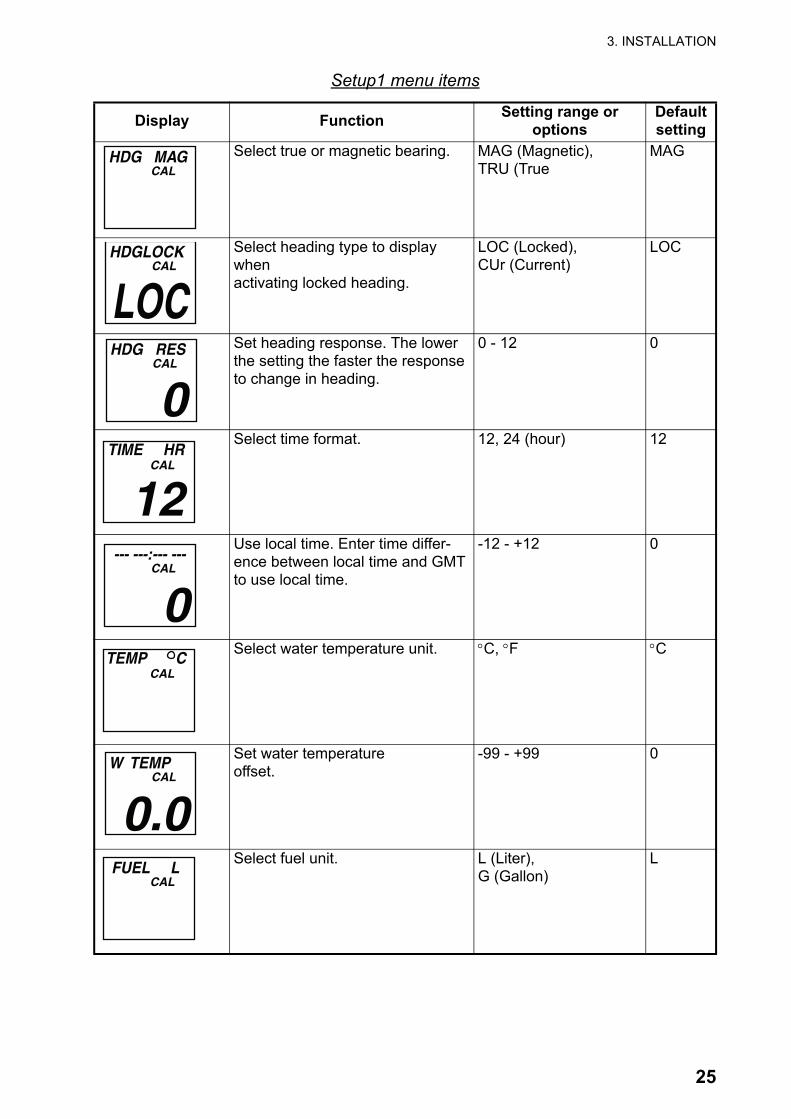
25
Select true or magnetic bearing. MAG (Magnetic),TRU (True
MAG
Select heading type to display whenactivating locked heading.
LOC (Locked),CUr (Current)
LOC
Set heading response. The lower the setting the faster the response to change in heading.
0 - 12 0
Select time format. 12, 24 (hour) 12
Use local time. Enter time differ-ence between local time and GMT to use local time.
-12 - +12 0
Select water temperature unit. °C, °F °C
Set water temperatureoffset.
-99 - +99 0
Select fuel unit. L (Liter),G (Gallon)
L
Setup1 menu items
Display Function Setting range or options
Defaultsetting
HDG MAG CAL
HDGLOCK CAL
LOC HDG RES
CAL
0TIME HR
CAL
12--- ---:--- ---
CAL
0TEMP C
CAL
W TEMPCAL
0.0FUEL L
CAL
3. INSTALLATION
26
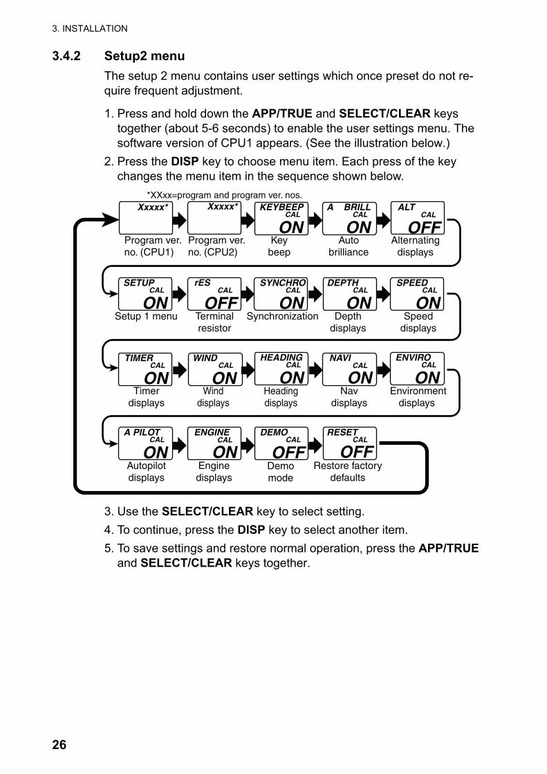
3.4.2 Setup2 menuThe setup 2 menu contains user settings which once preset do not re-quire frequent adjustment.
1. Press and hold down the APP/TRUE and SELECT/CLEAR keys together (about 5-6 seconds) to enable the user settings menu. The software version of CPU1 appears. (See the illustration below.)
2. Press the DISP key to choose menu item. Each press of the key changes the menu item in the sequence shown below.
3. Use the SELECT/CLEAR key to select setting.4. To continue, press the DISP key to select another item.5. To save settings and restore normal operation, press the APP/TRUE
and SELECT/CLEAR keys together.
Xxxxx*
Program ver.no. (CPU2)
Xxxxx*
Program ver.no. (CPU1)
KEYBEEPCAL
Keybeep
ONAuto
brilliance
A BRILLCAL
ONALT
Alternatingdisplays
CAL
OFF
Setup 1 menu
SETUPCAL
ONTerminalresistor
rESCAL
OFFSynchronization
SYNCHROCAL
ONDepth
displays
DEPTHCAL
ONSpeed
displays
SPEEDCAL
ON
Environmentdisplays
ENVIROCAL
ONNav
displays
NAVICAL
ONHeadingdisplays
HEADINGCAL
ONWind
displays
WINDCAL
ONTimer
displays
TIMERCAL
ON
Autopilotdisplays
A PILOTCAL
ONEnginedisplays
ENGINECAL
ONDemomode
DEMOCAL
OFFRestore factory
defaults
RESETCAL
OFF
*XXxx=program and program ver. nos.

3. INSTALLATION
27
Setup2 menu items
Display Function Setting range oroptions
Defaultsetting
Software version of CPU1.X=program no. and xxxx=program version no.
- -
Software version of CPU2.X=program no. and xxxx=program version no.
- -
Turn key beep on/off. ON, OFF ON
Auto brilliance on/off. ON, OFF ON
Enable/disable alternating displays.
OFF1: Depth/boat spd2: Boat spd/water temp.3: Depth/water temp.4: Depth/boat spd/water temp.5: Roll/pitch6: Latitude/Longitude
OFF
Enable/disable access to the setup1 menu.
ON, OFF ON
Turn the terminal resistor on/off.
ON, OFF OFF
Turn on/off synchronization of FI-50 series instruments.
ON: Synchronize FI-50 instruments having this setting.OFF: Turn off synchronization.A: Synchronize FI-50 instru- ments having this setting.b: Synchronize FI-50 instru- ments having this setting.
ON
Turn depth displays on/off. ON, OFF ON
Turn speed displays on/off. ON, OFF ON
Xxxxx
Xxxxx
KEYBEEPCAL
ONA BRILL
CAL
ONALT
CAL
OFF
SETUPCAL
ONrES
CAL
OFFSYNCHRO
CAL
ON
DEPTHCAL
ONSPEED
CAL
ON

3. INSTALLATION
28
Turn timer displays on/off. ON, OFF ON
Turn wind displays on/off. ON, OFF ON
Turn heading displays on/off. ON, OFF ON
Turn navigation displayson/off.
ON, OFF ON
Turn environmental displays on/off.
ON, OFF ON
Turn autopilot displays on/off. ON, OFF ON
Turn engine displays on/off. ON, OFF ON
Demo mode. To enable, press the SELECT/CLEAR key. Depth is shown. To disable and return to this menu, press and hold down the SELECT/CLEAR key.
ON, OFF OFF
Restore factory defaults.To restore factory defaults, press and hold down the SELECT/CLEAR key to show ON. Press the key again. A beep sounds upon completion.
ON, OFF OFF
Setup2 menu items
Display Function Setting range oroptions
Defaultsetting
TIMERCAL
ONWIND
CAL
ONHEADING
CAL
ONNAVI
CAL
ONENVIRO
CAL
ONA PILOT
CAL
ONENGINE
CAL
ONDEMO
CAL
OFF
RESETCAL
OFF
FI-504 MULTI
E7269S01A1 SP-1
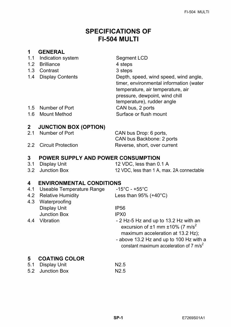
SPECIFICATIONS OF FI-504 MULTI
1 GENERAL 1.1 Indication system Segment LCD 1.2 Brilliance 4 steps 1.3 Contrast 3 steps 1.4 Display Contents Depth, speed, wind speed, wind angle, timer, environmental information (water temperature, air temperature, air
pressure, dewpoint, wind chill temperature), rudder angle
1.5 Number of Port CAN bus, 2 ports 1.6 Mount Method Surface or flush mount 2 JUNCTION BOX (OPTION) 2.1 Number of Port CAN bus Drop: 6 ports,
CAN bus Backbone: 2 ports 2.2 Circuit Protection Reverse, short, over current 3 POWER SUPPLY AND POWER CONSUMPTION 3.1 Display Unit 12 VDC, less than 0.1 A 3.2 Junction Box 12 VDC, less than 1 A, max. 2A connectable 4 ENVIRONMENTAL CONDITIONS 4.1 Useable Temperature Range -15°C - +55°C 4.2 Relative Humidity Less than 95% (+40°C) 4.3 Waterproofing Display Unit IP56 Junction Box IPX0 4.4 Vibration - 2 Hz-5 Hz and up to 13.2 Hz with an excursion of ±1 mm ±10% (7 m/s2 maximum acceleration at 13.2 Hz);
- above 13.2 Hz and up to 100 Hz with a constant maximum acceleration of 7 m/s2
5 COATING COLOR 5.1 Display Unit N2.5 5.2 Junction Box N2.5
FI-507 MULTI XL
SP - 2 E7277S01A
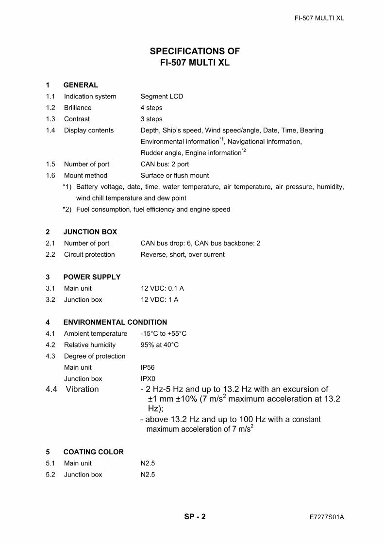
SPECIFICATIONS OF FI-507 MULTI XL
1 GENERAL 1.1 Indication system Segment LCD
1.2 Brilliance 4 steps
1.3 Contrast 3 steps
1.4 Display contents Depth, Ship’s speed, Wind speed/angle, Date, Time, Bearing
Environmental information*1, Navigational information,
Rudder angle, Engine information*2
1.5 Number of port CAN bus: 2 port
1.6 Mount method Surface or flush mount
*1) Battery voltage, date, time, water temperature, air temperature, air pressure, humidity,
wind chill temperature and dew point
*2) Fuel consumption, fuel efficiency and engine speed
2 JUNCTION BOX 2.1 Number of port CAN bus drop: 6, CAN bus backbone: 2
2.2 Circuit protection Reverse, short, over current
3 POWER SUPPLY 3.1 Main unit 12 VDC: 0.1 A
3.2 Junction box 12 VDC: 1 A
4 ENVIRONMENTAL CONDITION 4.1 Ambient temperature -15°C to +55°C
4.2 Relative humidity 95% at 40°C
4.3 Degree of protection
Main unit IP56
Junction box IPX0 4.4 Vibration - 2 Hz-5 Hz and up to 13.2 Hz with an excursion of
±1 mm ±10% (7 m/s2 maximum acceleration at 13.2 Hz);
- above 13.2 Hz and up to 100 Hz with a constant maximum acceleration of 7 m/s2
5 COATING COLOR 5.1 Main unit N2.5
5.2 Junction box N2.5

NAME
OUTLINE
Q'TY
DESCRIPTION/CODE №
PA
CK
ING
L
IST
26AA-X-9860-4
FI-504
1/1
NAME
OUTLINE
Q'TY
DESCRIPTION/CODE №
ユニ
ット
UNIT
表示部
MONITOR UNIT
1FI-504
000-011-745-00
工事
材料
INSTALLATION MATERIALS
CP26-00600
+ナベタッピンネジ 1シュ
SELF-TAPPING SCREW
43X20 SUS304
000-163-884-10
ケーブル組品
CABLE ASSEMBLY
1FI-50-DROP-6M
001-105-810-10
ケーブル組品0.3M
CABLE ASSEMBLY 0.3M
1FI-50-CHAIN-0.3M
001-105-820-10
サーフェスマウントスポンジ
SPONGE
1TZ7583002AO
000-167-832-10
パネルリムーハ
゙ー
PANEL REMOVER
119-028-3124-1
100-340-471-10
バネ座金
SPRING WASHER
2M3 SUS304
000-167-404-10
ミガキ丸
平座金
FLAT WASHER
2M3 SUS304
000-167-453-10
寸切ボルト
BOLT
2M3X40 SUS304
000-167-804-10
蝶ナット
WING NUT
2M3 SUS304
000-167-826-10
図書
DOCUMENT
取扱説
明書(英
)
OPERATOR'S MANUAL
1OME-72690-*
000-167-334-1*
操作要
領書
OPERATOR'S GUIDE
1
**
OS*-72690-*
000-167-295-1*
内部終
端ノ設
定
INTERNAL RESISTOR
SETTING
1C72-00705-*
000-168-501-1*
コ-ド
番号
末尾
の[*
*]は
、選
択品
の代
表コー
ドを
表し
ます
。
CO
DE N
UM
BER
EN
DIN
G W
ITH
"**" IN
DIC
ATES T
HE C
OD
E N
UM
BER
OF R
EP
RESEN
TA
TIV
E M
ATER
IAL.
(略
図の
寸法
は、
参考
値で
す。
DIM
EN
SIO
NS IN
DR
AW
ING
FO
R R
EFER
EN
CE O
NLY.)
26AA-X-9860
型式
/コー
ド番
号が
2段
の場
合、
下段
より
上段
に代
わる
過渡
期品
であ
り、
どち
らか
が入
って
いま
す。
な
お、
品質
は変
わり
ませ
ん。
TW
O T
YP
ES
AN
D C
OD
ES
MA
Y B
E L
ISTED
FO
R A
N ITEM
. T
HE L
OW
ER
PR
OD
UC
T M
AY B
E S
HIP
PED
IN
PLA
CE O
F
TH
E U
PP
ER
PR
OD
UC
T. Q
UA
LIT
Y IS
TH
E S
AM
E.
NAME
OUTLINE
Q'TY
DESCRIPTION/CODE №
PA
CK
ING
L
IST
26AA-X-9863-2
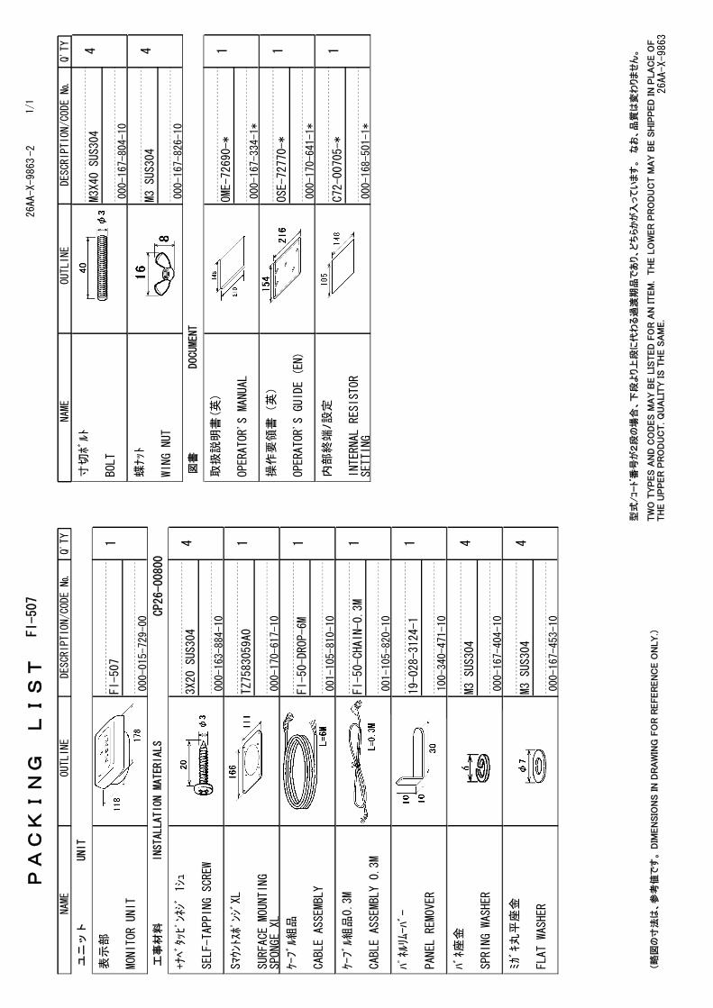
FI-507
1/1
NAME
OUTLINE
Q'TY
DESCRIPTION/CODE №
ユニ
ット
UNIT
表示部
MONITOR UNIT
1FI-507
000-015-729-00
工事
材料
INSTALLATION MATERIALS
CP26-00800
+ナベタッピンネジ 1シュ
SELF-TAPPING SCREW
43X20 SUS304
000-163-884-10
SマウントスポンジXL
SURFACE MOUNTING
SPONGEXL
1TZ7583059A0
000-170-617-10
ケーブル組品
CABLE ASSEMBLY
1FI-50-DROP-6M
001-105-810-10
ケーブル組品0.3M
CABLE ASSEMBLY 0.3M
1FI-50-CHAIN-0.3M
001-105-820-10
パネルリムーハ
゙ー
PANEL REMOVER
119-028-3124-1
100-340-471-10
バネ座金
SPRING WASHER
4M3 SUS304
000-167-404-10
ミガキ丸
平座金
FLAT WASHER
4M3 SUS304
000-167-453-10
寸切ボルト
BOLT
4M3X40 SUS304
000-167-804-10
蝶ナット
WING NUT
4M3 SUS304
000-167-826-10
図書
DOCUMENT
取扱説
明書(英
)
OPERATOR'S MANUAL
1OME-72690-*
000-167-334-1*
操作要
領書(英)
OPERATOR'S GUIDE (EN)
1OSE-72770-*
000-170-641-1*
内部終
端ノ設
定
INTERNAL RESISTOR
SETTING
1C72-00705-*
000-168-501-1*
(略
図の
寸法
は、
参考
値で
す。
DIM
EN
SIO
NS IN
DR
AW
ING
FO
R R
EFER
EN
CE O
NLY.)
26AA-X-9863
型式
/コー
ド番
号が
2段
の場
合、
下段
より
上段
に代
わる
過渡
期品
であ
り、
どち
らか
が入
って
いま
す。
な
お、
品質
は変
わり
ませ
ん。
TW
O T
YP
ES
AN
D C
OD
ES
MA
Y B
E L
ISTED
FO
R A
N ITEM
. T
HE L
OW
ER
PR
OD
UC
T M
AY B
E S
HIP
PED
IN
PLA
CE O
F
TH
E U
PP
ER
PR
OD
UC
T. Q
UA
LIT
Y IS
TH
E S
AM
E.

26/Oct/09 R.Esumi
26/Oct/09 R.Esumi

Jul.24'07 R.Esumi

9/Dec/08 R.Esumi

9/Dec/08 R.Esumi

12VDC
24
3
A
1
B C
NOTE
*1:OPTION.
*2:USE
ATERMINALBOX(NO-PROTECTION)WHENTHE
SUPPLIEDCABLE
ISCUT.
注記
*1)オ
プショ
ン。
*2)ケ
ーブル
を切断
する
場合
は、
ター
ミナル
ボッ
クス(非防水)を使用のこと。
*3)短
絡しな
いよう
に、
端末
を処
理す
る。
*3:PROTECTCABLEENDSTOPREVENTSHORT-CIRCUIT.
DRAWN
CHECKED
APPROVED
DWG.No.
TITLE
NAME
名称
INTERCONNECTION
DIAGRAM
相互
結線図
REF.No.
SCALE
MASS
kg
インスツ
ルメント
INSTRUMENT
T.YAMASAKI
T.TAKENO
FI-501/502/503/504/505/506/507
1 2 3 4 5
SHIELD
NET-S
NET-C
NET-H
NET-L
1 2 3 4 5
SHIELD
NET-S
NET-C
NET-H
NET-L
1 2 3 4 5
SHIELD
NET-S
NET-C
NET-H
NET-L
1 2 3 4 5
SHIELD
NET-S
NET-C
NET-H
NET-L
1 2 3 4 5
SHIELD
NET-S
NET-C
NET-H
NET-L
1 2 3 4 5
SHIELD
NET-S
NET-C
NET-H
NET-L
同上
DITTO
同上
DITTO
同上
DITTO
同上
DITTO
RED
アカ
BLK
クロ
チャ
BRN
ダイ
キORG
YEL
1 2 3 4 5 6
TERMINALBOX
FI-5001-TERMINAL
ターミナルボックス *2
WINDTRANSDUCER
風向
風速
セン
サー
SHIELD
NET-S
NET-C
NET-H
NET-L
1 2 3 4 5
イン
スツ
ルメ
ント
INSTRUMENT
-SR7000
LTW12-05AFFM
FI-501/502
単品
で使
用す
ると
きUSINGINDEPENDENTLY
RED
BLK
アカ
クロ
シロ
アオ
WHT
BLU
FI-50-DROP,6m,φ
6
12VDC(+)
(-)
(1/5/10/20m*1)FI-50-CHAIN,0.3m,φ6
SHIELD
NET-S
NET-C
NET-H
NET-L
1 2 3 4 5
インスツルメ
ント
INSTRUMENT
SHIELD
NET-S
NET-C
NET-H
NET-L
1 2 3 4 5
FI-503/504
505/506
-SR7000
LTW12-05AFFM
-SR7000
LTW12-05AMMM
(1/5/10/20m*1)FI-50-CHAIN,0.3m,φ6
RED
BLK
アカ
クロ
シロ
アオ
WHT
BLU
RED
BLK
アカ
クロ
シロ
アオ
WHT
BLU
FI-50-DROP,6m,φ6
FI-50-DROP,6m,φ6
SHIELD
NET-S
NET-C
NET-H
NET-L
1 2 3 4 5
インスツルメ
ント
INSTRUMENT
FI-501/502
SHIELD
NET-S
NET-C
NET-H
NET-L
1 2 3 4 5
1 2 3 4 5 6
WIND
GND
SPEED
DIR2
DIR1+V
SHIELD
-SR7000
-SR7000
LTW12-05AFFM
LTWBD-06AFMM
LR7000
LTW12-05AMMM
FI-50-SENSOR-30M/50M,30/50m,φ
4.3
SELECT
選択
NCNC
*3
インスツルメ
ント
(最
大26個
)INSTRUMENT
(TOTAL:
UPTO
26
SETS)
DEPENDONCABLEANDCONNECTIONCONDITIONS
ケー
ブル
や接
続条
件に
より
満足
しな
い場
合あ
り
FI-5001/5001L
507
CN3
DROP_U
CN3
DROP_L
CN4
DROP_U
CN4
DROP_L
CN5
DROP_U
CN5
DROP_L
(+)
(-)
BLK
クロ
SHIELD
1 2 3
ジャン
クシ
ョンボックス
FI-5002
*1
JUNCTIONBOX
1 2 3 4 5
SHIELD
NET-S
NET-C
NET-H
NET-L
1 2 3 4 5
SHIELD
NET-S
NET-C
NET-H
NET-L
接続
箱JUNCTION
BOX
接続
箱JUNCTION
BOX
(BACKBONE)
(BACKBONE)
CN112VDC
CN2BACKBONE_U
CN2BACKBONE_L
CANbusNETWORK
CANbusNETWORK
CAN
bus
CABLE
TOTAL
LENGTH:
UPTO
80m
CAN
busケーブル長総
合計:
80m以下
CAN
bus
CAN
bus
CAN
bus
CAN
bus
CANbus
シロ
WHT
(VV-SA0.75x2C)
FI-5002-POWERCABLE,2m
28/Jan/10
28/Jan/10
C7266-C01-
J
8/Mar/10 R.Esumi

タッピンネジ用穴(4ヵ所)For tapping screws (4 pcs.)
寸切りボルト用穴(2ヵ所)For bolts (2 pcs.)
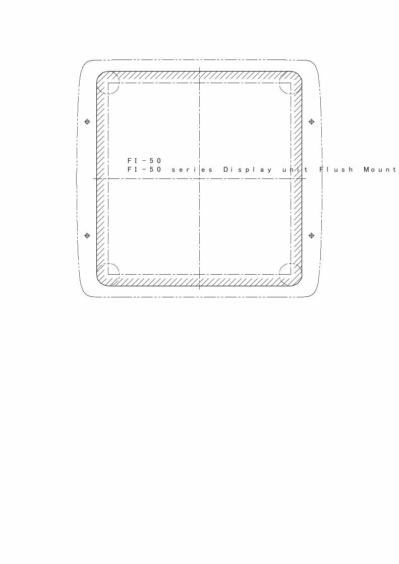
FI-50シリーズ 表示部 フラッシュマウント用型紙FI-50 series Display unit Flush Mount Template
タッピンネジ用穴 (4カ所)
For t
appi
ng s
crew
s (4
pcs
.)
寸切りボルト用穴 (4カ所)
For bolts
(4 p
cs.)
FI-5
07 フ
ラッシュマウント用型紙
FI-5
07 F
lush
Mou
nt T
emle
te