Embed Size (px)
DESCRIPTION
gh
Citation preview
HAI Project #5348-003
Fire Hazard Analysis of Composite Resin Manufacturing
Spray Application Areas
Prepared by
Joseph L. Scheffey, P.E. Craig L. Beyer, Ph.D.
Hughes Associates, Inc. 3610 Commerce Drive, Suite 817
Baltimore, MD 21227 Ph. 410-737-8677 FAX 410-737-8688
Prepared for
American Composites Manufacturers Association 1010 North Glebe Road, Suite 450
Arlington, VA 22201
and
National Marine Manufacturers Association 444 North Capitol St.
Suite 645 Washington, DC 20001
Final Report October 19, 2007

ii
TABLE OF CONTENTS
Page
1.0 BACKGROUND ................................................................................................................ 1
2.0 INDUSTRY BACKGROUND AND TERMINOLOGY ................................................... 4
2.1 Basic Chemistry of Reinforced Plastics Manufacturing................................................. 4 2.2 Manufacturing Processes ................................................................................................ 5 2.3 Terminology.................................................................................................................... 6
2.3.1 Industry Terminology ............................................................................................. 6 2.3.2 NFPA Terminology ................................................................................................ 7
3.0 REVIEW OF NFPA 33 REQUIREMENTS AND LEVEL OF SAFETY ESTABLISHED.................................................................................................................. 8
3.1 Scope, Purpose and Definitions .................................................................................... 16 3.2 Electrical ....................................................................................................................... 17 3.3 Ventilation..................................................................................................................... 18 3.4 Liquid Handling and Storage ........................................................................................ 19 3.5 Protection ...................................................................................................................... 20 3.6 Prevention of Ignition Sources...................................................................................... 21 3.7 Summary of Comparison .............................................................................................. 21
4.0 SUMMARY OF WALKDOWNS .................................................................................... 22
4.1 General Facility Information......................................................................................... 22 4.1.1 Facility Manufacturing.......................................................................................... 22 4.1.2 Fire Suppression Systems ..................................................................................... 23
4.2 Chemicals...................................................................................................................... 23 4.3 Resin Application Areas ............................................................................................... 25 4.4 Application Equipment ................................................................................................. 25
4.4.1 Pump and Spray Gun ............................................................................................ 25 4.4.2 Grounding of Equipment ...................................................................................... 27 4.4.3 Clean-up................................................................................................................ 27
4.5 Ventilation System........................................................................................................ 27 4.6 Overspray...................................................................................................................... 28
4.6.1 Enclosures ............................................................................................................. 28 4.6.2 Open Areas............................................................................................................ 28
4.7 Electrical Equipment..................................................................................................... 28 4.7.1 Within Partial Enclosures ..................................................................................... 28 4.7.2 Outside Partial Enclosures .................................................................................... 29
4.8 Chemical Storage .......................................................................................................... 29 4.9 Prevention of Ignition Sources...................................................................................... 29
5.0 FIRE HAZARD ANALYSIS ........................................................................................... 30
5.1 Hazards ......................................................................................................................... 30 5.2 Areas and Applications Where the Hazard Occurs....................................................... 30
5.2.1 Spray Area, Including Spray Piping Equipment and Gun. ................................... 30 5.2.2 Piping System between the Spray and Local Storage Area/Pump Station ........... 32
iii
5.2.3 Local Storage within Spray Area (NFPA 30-2007 definition) ............................. 32 5.3 Mitigation of Hazards to Personnel .............................................................................. 33
5.3.1 Use of Non-combustible or Limited Combustible Liquids................................... 33 5.3.2 Ignition Prevention................................................................................................ 34
5.4 Catalyst Use and Storage .............................................................................................. 39 5.5 Mitigation Through Automatic Fire Suppression......................................................... 40
6.0 FIRE LOSS HISTORY..................................................................................................... 40
6.1 NFPA Data.................................................................................................................... 40 6.2 Data from NFPA 33 ...................................................................................................... 42 6.3 Qualitative Information................................................................................................. 43
7.0 VAPOR/SPRAY CHARACTERISTICS IN RESIN APPLICATION AREAS AND ELECTRICAL CLASSIFICATION REQUIREMENTS................................................. 43
7.1 Vapor/Spray Characteristics ......................................................................................... 43 7.2 Electrical Classification Requirements ......................................................................... 45
8.0 CONCLUSIONS AND SUMMARY OF HAZARDS AND LEVEL OF SAFETY........ 47
9.0 RECOMMENDATIONS.................................................................................................. 51
10.0 REFERENCES ................................................................................................................. 52
11.0 ACKNOWLEDGEMENTS.............................................................................................. 53
APPENDIX A – DETAILED NOTES OF FACILITY WALKDOWNS .................................. A-1 TABLE A-1 ................................................................................................................................ A-2 FACILITY 1 ............................................................................................................................... A-3 FACILITY 2 ................................................................................................................................B-1 FACILITY 3 ................................................................................................................................C-1 FACILITY 5 ............................................................................................................................... D-1
1
PRELIMINARY FIRE HAZARD ANALYSIS OF COMPOSITE RESIN MANUFACTURING
SPRAY APPLICATION AREAS
1.0 BACKGROUND
The fire safety hazards of spray application operations in the composites resin manufacturing industry (“composite spray applications” or “CSA”) are governed by 29 C.F.R. § 1910.107, Spray Finishing Using Flammable And Combustible Materials, which was adopted by the Occupational Safety and Health Administration (OSHA) in 1972. The provisions of § 1910.107 are essentially identical to the “mandatory” provisions of NFPA 33-1969. This is the 1969 Edition of National Fire Protection Association (NFPA) Standard for Spray Application Using Flammable or Combustible Material [1]. While § 1910.107 has remained substantially unchanged since its adoption by OSHA in 1972, NFPA 33 has been periodically updated to reflect significant advances in the understanding of the fire safety hazards presented by many of the covered operations.
Based on these advances, a specific chapter specially designed for composites manufacturing, “Styrene Cross-Linked Composites Manufacturing (Glass Fiber–Reinforced Plastics)” (also known as the “GFRP Chapter”), was first adopted in NFPA 33-19951 and has been retained as Chapter 17 of the 2003 and 2007 Editions of NFPA 33. The requirements of the GFRP Chapter are less stringent than the requirements of NFPA 33 that previously applied (and would otherwise still apply) to CSA. This differential treatment of CSA reflects a determination by the NFPA 33 Committee that:
1) The fire safety hazards and risks presented by CSA are inherently lower than the fire safety hazards and risks presented by the other spray application operations covered by the generally-applicable provisions of § 1910.107 (and NFPA 33); and
2) The less stringent provisions of the GFRP Chapter (of NFPA 33-2007 and its predecessors) provide a level of fire safety protection for CSA operations that is both effective and substantially equivalent to the level of protection provided by the generally-applicable provisions of NFPA 33-2007 (and, by implication, § 1910.107 and NFPA 33-1969) to those other spray application operations.
Based on the action taken by the NFPA 33 Committee in adopting the GFRP Chapter, and the underlying rationale, the National Marine Manufacturers Association (NMMA)2 and the American Composites Manufacturers Association (ACMA) filed petitions with OSHA asking the agency to amend Section 1910.107 by incorporating the requirements of the GFRP Chapter (of NFPA 33-1995 and NFPA 33-2003, respectively). Substantial technical documentation was submitted to OSHA by NMMA and ACMA in support of those petitions. After reviewing those submissions, OSHA indicated that the information it had received was helpful, but was not adequate to demonstrate that this situation met the criteria for an expedited consensus standards
1 Chapter 15 of NFPA 33-1995. 2 The NMMA petition was dated December 1, 2001; the ACMA petition was dated August 17, 2004.
2
update. The industry had not demonstrated that the less stringent provisions of the GFRP Chapter provided a level of fire safety protection for CSA operations that is substantially equivalent to the level of protection provided by the generally-applicable provisions of § 1910.107 and NFPA 33-1969 to the other spray application operations covered by those standards.
Accordingly, in a Federal Register notice associated with its consensus standards update initiative3, OSHA announced that it was “exploring the idea of amending Sec. 1910.106 and Sec. 1910.107, at this time, to allow employers to comply with the 2003 Eeditions of NFPA 30 and 33 until the more extensive revision is completed” and sought information that would satisfy the criteria for an expedited consensus standards update. With that objective in mind, representatives of NMMA and ACMA met with OSHA to get a better understanding of the information the agency believed would be required for this purpose.
Based on that meeting, NMMA and ACMA agreed to develop a Fire Hazard Analysis (FHA) that would be useful in determining whether the level of fire safety protection provided by NFPA 33-2003 (or NFPA 33-2007) for CSA is appropriate to ensure worker safety under the criteria established by the Occupational Safety and Health Act (“OSH Act”). The presumption was that the protection provided by the GFRP Chapter would be adequate if: 1) the fire safety hazards and risks presented by CSA are substantially lower than the fire safety hazards and risks presented by the other spray application operations covered by the generally-applicable provisions of § 1910.107 (and NFPA 33-1969); and 2) the provisions of the GFRP Chapter 17 provide a level of fire safety protection for CSA operations that is substantially equivalent to the level of protection provided by the generally-applicable provisions of § 1910.107 (and NFPA 33-1969) to those other spray application operations.
In performing a FHA, it is important to keep in mind that the FHA takes a conservative approach in identifying hazards, and is likely to identify potential hazards that are beyond the scope of the hazards that are addressed, or could reasonably be expected to be addressed, by the applicable standard. NFPA 33-2007 is designed to provide fire safety requirements appropriate for “anticipate[d] conditions of average use” (emphasis added) rather than “unusual industrial processes”:
“The purpose of this standard shall be to provide requirements for fire safety for spray application of flammable or combustible materials. This standard anticipates conditions of average use. Where unusual industrial processes are involved, the authority having jurisdiction shall be permitted to require additional safeguards or modifications to the requirements of this standard, provided equivalent safety is achieved.”
This statement of purpose is consistent with the statement of purpose in NFPA 33-1969, which provides the text of Section 1910.107 and states that it was designed to provide “practical minimum requirements to obtain reasonable safety under average contemplated conditions…”
The understanding was that this FHA should be performed in a way that takes into account the hazards posed by plausible worst-case CSA operating conditions presented by composites resin spray applications and related storage, handling, and clean-up activities. However, for the
3 ANPRM, 71 FR 76623-76630, December 21, 2006.
3
reasons stated above, it should be recognized that many of the plausible worst case scenarios are beyond the scope of what would realistically be addressed by Section 1910.107.
This FHA is intended to be a preliminary, comprehensive assessment to identify and address potential fire scenarios and associated variables. It includes the following:
1. A general overview of the industry and relevant processes;
2. Identification of plausible fire safety hazards posed by the manufacturing processes, and the storage and handling of the materials used in those processes;
3. A direct comparison of requirements of NFPA 33-1969 with the requirements of NFPA 33-2007 applicable to CSA. NFPA 33-2007 [2] is used since it is the most up-to-date version of NFPA 33 and represents the current state-of-the-art;
4. Site visits to representative manufacturers, which included extensive walk-throughs of facilities with spray enclosures and a marine fabrication facility having open spray areas;
5. For the relevant processes, identification of the:
a. Chemicals used: the unsaturated polyester resins, the reactive diluents (styrene), the catalyst (curing agent, such as methyl ethyl ketone peroxide (MEKP)), and any clean-up agents such as acetone.
b. Spray application processes: chopped fiber and gel coat.
c. Spray application methods/techniques: air-atomized, high pressure airless, air-assist, airless, and high volume low pressure spray techniques.
c. Spray process and equipment characteristics: pressure, flow (and associated viscosity), failsafe equipment, power (pneumatic, hydraulic, electrical) and operator training.
d. Spray process areas: enclosed, partially enclosed, and open areas;
e. Ignition hazards.
f. Mitigation of vapors – ventilation and adoption of controlled spray programs/techniques including overspray containment flanges.
g. Storage of chemicals used: unsaturated polyester resins, catalyst (MEKP), and clean-up materials such as acetone.
h. Life safety attributes within the spray area and for the building housing the CSA process and material storage.
6. A review of loss data in the industry.
7. Analysis of the dynamics of sprays and vapors created in resin application areas. Emissions data already available from the industry was reviewed. For example, emissions data may provide an indication of the processes where vapors are most likely to occur.
8. Development of bounding scenarios – a detailed hazard analysis was performed that included:
4
a. Probability of ignition source;
b. Potential for ignitable vapor concentration; and
c. Consequences of ignitable vapor condition, particularly with respect to personnel safety.
9. Determination of the need for quantification/test data to support the final fire hazard analysis.
2.0 INDUSTRY BACKGROUND AND TERMINOLOGY
2.1 Basic Chemistry of Reinforced Plastics Manufacturing
Reinforced plastics manufacturing involves automatically proportioning mixtures of resin monomer and an organic peroxide. Polyester resin is a chemical chain linking organic acids and alcohols with an ester linkage (thus its name, polyester). Styrene is the most commonly used cross-linking agent that connects the polyester chains and creates a polyester resin which is liquid and flexible for the fabrication of parts.
Styrene, as a cross-linking agent, reacts with the available bond sitting on the polyester chain, commonly an unsaturated organic acid. The acid reacts more rapidly with styrene than styrene does with itself, thereby linking the chemical chain into a network structure that becomes solid.
When the resin arrives at the fiberglass-reinforced plastics plant, it is in a liquid form. This typically is a polyester, thinned with approximately 30–45% styrene monomer, and mixed with chemical inhibitors to prevent a spontaneous cross-linking reaction. Controlling the polymerization reaction requires the use of catalysts, promoters, temperature, and time. In fabrication, this reaction, where the resin goes from liquid to solid, varies with the specific requirements of the desired product.
MEKP can be used in concert with promoters. Promoters speed up the activity of MEKP, reducing the required temperature for the reaction. A common promoter is the organic salt of cobalt. In most cases, the premixed resin already contains the promoters.
The viscous resin is either mixed with, sprayed or brushed onto glass-reinforcing material. Fiberglass comes in either a woven mat or cord-like roving which is applied with resin during fabrication. Fillers or thickeners (thixotropic agents) are particulate powders that can be stirred into the resin mix to provide additional body.
Once reacted, or polymerized, polyester resins are thermosetting, meaning when they are cured they cannot be softened and reshaped by heat. If properly cured, the hardened finished product does not release vapors into the atmosphere. Polyester resin in spray-up/lay-up operations is generally used with a clean-up solvent, most often acetone.
Fiberglass reinforced polyester resins create products noted for strength and durability, such as boats, spas, bath/showers, tanks and recreational vehicles.
5
In a lamination process, resin is mixed with fiberglass mat, or roving, and sprayed. Gel coat application refers to pigmented or clear resin sprayed onto molds as the first layer in a lamination process.
2.2 Manufacturing Processes
There are two general divisions of composites manufacturing processes: (1) open molding, where gel coat and laminate are exposed to the atmosphere during the fabrication process; and, (2) closed molding, where a two-sided mold set or vacuum bag is used. Since spray application is used in the open molding process, that process is the focus of this analysis.
The open molding process involves saturating a reinforcement fiber with resin, then using manual roll-out techniques to consolidate the laminate and remove entrapped air. A major factor in this operation is the transfer of resin from a drum or storage tank to the mold. The means used to transport the resin, in many cases, characterizes the specific process method. For example, if the resin is applied manually, using a bucket and brush, the process is known as Hand Lay-Up. If resin is applied using a traditional chopper gun, the process is referred to as Spray-Up. In years past, the lines between spray applied hand lay-up and spray-up have been somewhat blurred.4 In order to clarify the methods being used, the industry has developed more accurate descriptions of the processes. The Molding Process is defined by the method of fiber placement (i.e., by hand, or by mechanical chopping). The Resin Application Method is defined by the means used to transfer resin to the mold.
In the hand lay-up laminate process, fiber/roll stock reinforcements (such as chopped strand mat, or woven, knitted, or textile fabrics), are placed by hand and then saturated with resin. Resin can be applied either by manual or mechanical means. In the chopped laminate process, a chopper applicator is used. This cuts continuous strand roving into short fiber lengths, and deposits resin and fiber, known as “chop,” on a mold surface. This process includes traditional atomized chopping (spray-up) as well as non-atomized flow chop application.
Resin application is via manual or mechanical means. In manual application, the thermoset resin is manually transferred from a container to a fiber reinforcement. Bucket and tool application is used, with the resin being hand mixed in a container and manually applied to the laminate with a brush, paint roller, squeegee, or other tool.
Mechanical application involves applying a thermoset resin to a fiber reinforcement using a fluid delivery device. This could involve one of the following techniques:
• Mechanical non-spray, including pressure-fed rollers and resin impregnators. Pressurized resin streams are not directed through the air in these processes.
• Mechanical spray, where pressurized resin streams are directed through the air.
4 If one were wetting out roll stock materials (e.g., chopped strand mat or knitted fabric) with a spray gun, the method would be referred to as hand lay-up, even though the resin was applied by spray application. By virtue of the reinforcement being applied by hand, as opposed to chopper gun application, the molding process is hand lay-up, while the resin application is atomized spray.
6
These processes include:
• Controlled Spraying – Spray gun pressure calibration verified, mold containment flanges in place, and operator training documented as outlined in the CFA Controlled Spraying Handbook [3]. All three elements must be in place to qualify as Controlled Spray Application.
• Low-emission Application – Includes flow coaters, flow choppers, non-atomized spray guns, impingement guns, and other spray devises designed to deliver resin at lower emission rates, typically by reducing the surface area of the material as it is sprayed. For maximum effectiveness in reducing emissions, these techniques should be combined with the operator training and pressure calibration components of Controlled Spray. The US EPA national air pollution control rule for the composites industry refers generically to low-emission application processes as “non-atomized mechanical application,” and requires employers to have emission test data and follow operating instructions for these devices [40 CFR 63.5935].
Gel coat products are typically applied using traditional or low-emission mechanical spray.
Spray-up, or chopping, is a suitable process for making boats, tanks, transportation components and tub/shower units and hundreds of other products in a large variety of shapes and sizes. A chopped laminate has good conformability and is sometimes faster than hand lay-up in molding complex shapes. In the spray-up process the operator controls thickness and consistency, therefore the process is more operator dependent than hand lay-up. Gel coat is typically first applied to the mold prior to spray-up of the substrate laminate. Continuous strand glass roving and catalyzed resin are fed through a chopper gun, which deposits the resin-saturated “chop” on the mold. The laminate is then rolled to thoroughly saturate the glass strands and compact the chop. Additional layers of chop laminate are added as required for thickness. Roll stock reinforcements, such as woven roving or knitted fabrics, can be used in conjunction with the chopped laminates.
2.3 Terminology
2.3.1 Industry Terminology
The sections above provide an overview of the chemicals and processes. The following provides a quick reference of industry terminology:
• Catalyst – a substance added to the resin to accelerate the rate of curing. • Cleaning Materials – materials used for the cleaning of hands, tools, molds and spray
equipment associated with polyester resin operations, which may contain volatile organic compounds (VOCs).
• Cross-Linking – the process of joining two or more polymer chains together. • CSA – Composite spray applications. • Cure – the polymerization, i.e., the chemical reaction resulting in the transformation
from a liquid to a solid state, to achieve desired product physical properties, including hardness.
7
• Fiberglass – a fiber similar in appearance to wool or cotton fiber but made from glass.
• Gel Coat – a polyester resin surface coat, either colored or clear, providing a cosmetic enhancement and improvement to exposure resistance.
• GFRP – Glass fiber-reinforced plastics. • Inhibitor – a substance designed to slow down or prevent a chemical reaction. • MEKP – methyl ethyl ketone peroxide. • MMA – methyl methacrylate; a monomer used with styrene in some resin and gel coat
formulations to improve product performance. • Monomer –an organic compound that combines with itself or other similar
compounds by a cross-linking reaction to become a part of a cured thermosetting resin; styrene and MMA are the monomer commonly used in polyster resins.
• Neat – not diluted or mixed with other substances. • PEL – Permissible exposure limit. • Polyester – a complex polymeric ester, derived from difunctional acids and alcohols,
which is dissolved in a monomer. • Polyester Resin Operation – any of the following: mixing, pouring, hand lay-up,
injection, forming, spraying, and curing of polyester resin materials. • Polyester Resin Materials – unsaturated polyesters, cross-linking agents, catalysts, gel
coats, inhibitors, and any other material used in a polyester resin operation. • Polymer – a large chemical chain composed of repeating groups, such as polystyrene. • Resin – any of a class of organic polymers of natural or synthetic origin used in
reinforced products to surround and hold fibers, which is solid in the cured state. • Touch-up – that portion of the polyester resin operation that is necessary to cover
minor imperfections. • Vapor Suppressed Resin – a resin which has been modified to reduce the loss of
materials in the form of VOC emissions during polymerization.
2.3.2 NFPA Terminology
NFPA has updated and added to its terminology related to spray area (see Section 3.1 for a detailed review of the implications of this). Because the NFPA 33-2007 Edition provides generally better descriptions of variations in spray areas, these terms will generally be used in the analysis. The use of these terms does not imply a preconceived value judgment on associated protection. Rather, these terms simply provide better descriptions of actual manufacturing processes.
• Resin Application Area – any area in which polyester resins or gel coats are spray-applied.

8
• Spray Area – any fully-enclosed, partly-enclosed, or unenclosed area in which dangerous quantities of flammable or combustible vapors, mists, residues, dusts or deposits are present due to the operation of spray processes.
• Unenclosed Spray Area – any spray area that is not confined by a limited finishing workstation, spray booth, or spray room, as defined in NFPA 33.
• Chopper Gun – a device that feeds glass fiber roving through a cutting unit and injects the cut glass fibers into a stream of catalyzed liquid resin that is then sprayed onto a surface.
• Lower Flammable Limit (LFL) – the lowest flammable concentration of a gas in air in which a flame can be propagated when given a source of ignition.
• Overspray – any sprayed material that is not deposited on the intended object. • Spray Booth – a power-ventilated enclosure for a spray application operation or
process that confines and limits the escape of the material being sprayed, including vapors, mists, dusts and residues that are produce by the spraying operation and conducts or directs these materials to an exhaust system.
• Dry Type Spray Booth – a spray booth that is not equipped with a water-washing system to remove overspray from the exhaust airstream.
• Spray Room – a power-ventilated fully-enclosed room used exclusively for open spraying of flammable or combustible materials.
• Ventilation – For the purpose of NFPA 33, movement of air that is provided for the prevention of fire and explosion and is sufficient to prevent accumulation of vapor-air mixtures in concentrations over 25 percent of the lower flammable limit.
3.0 REVIEW OF NFPA 33 REQUIREMENTS AND LEVEL OF SAFETY ESTABLISHED
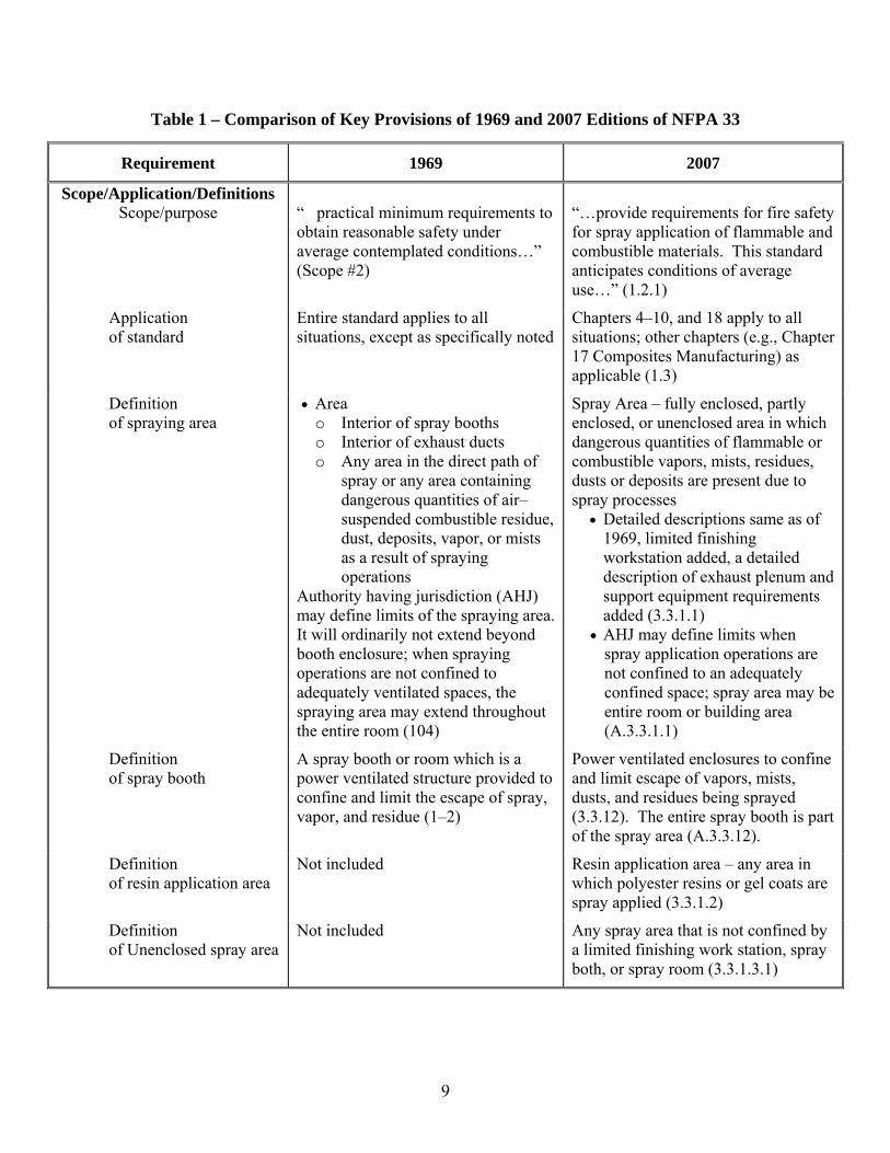
Requirements in NFPA 33 Standard for Spray Application Using Flammable or Combustible Materials establish the level of safety as enforced by OSHA. Requirements related to composite resin spray application were explicitly inserted in the 1995 Edition of NFPA 33. In order to identify quantitative and qualitative differences between old and new criteria, a review of pertinent spray application requirements was performed. The 1969 and 2007 Editions of NFPA 33 were reviewed. Applicable requirements are outlined in Table 1. Referenced paragraphs from the standards are noted in the parentheses. The relevant requirements reviewed included:
• Scope/Purpose • Definitions • Electrical • Ventilation • Liquid Handling and Storage • Protection • Prevention of Ignition Sources
9
Table 1 – Comparison of Key Provisions of 1969 and 2007 Editions of NFPA 33
Requirement 1969 2007
Scope/Application/Definitions Scope/purpose
“ practical minimum requirements to obtain reasonable safety under average contemplated conditions…” (Scope #2)
“…provide requirements for fire safety for spray application of flammable and combustible materials. This standard anticipates conditions of average use…” (1.2.1)
Application of standard
Entire standard applies to all situations, except as specifically noted
Chapters 4–10, and 18 apply to all situations; other chapters (e.g., Chapter 17 Composites Manufacturing) as applicable (1.3)
Definition of spraying area
• Area o Interior of spray booths o Interior of exhaust ducts o Any area in the direct path of
spray or any area containing dangerous quantities of air–suspended combustible residue, dust, deposits, vapor, or mists as a result of spraying operations
Authority having jurisdiction (AHJ) may define limits of the spraying area. It will ordinarily not extend beyond booth enclosure; when spraying operations are not confined to adequately ventilated spaces, the spraying area may extend throughout the entire room (104)
Spray Area – fully enclosed, partly enclosed, or unenclosed area in which dangerous quantities of flammable or combustible vapors, mists, residues, dusts or deposits are present due to spray processes
• Detailed descriptions same as of 1969, limited finishing workstation added, a detailed description of exhaust plenum and support equipment requirements added (3.3.1.1)
• AHJ may define limits when spray application operations are not confined to an adequately confined space; spray area may be entire room or building area (A.3.3.1.1)
Definition of spray booth
A spray booth or room which is a power ventilated structure provided to confine and limit the escape of spray, vapor, and residue (1–2)
Power ventilated enclosures to confine and limit escape of vapors, mists, dusts, and residues being sprayed (3.3.12). The entire spray booth is part of the spray area (A.3.3.12).
Definition of resin application area
Not included Resin application area – any area in which polyester resins or gel coats are spray applied (3.3.1.2)
Definition of Unenclosed spray area
Not included Any spray area that is not confined by a limited finishing work station, spray both, or spray room (3.3.1.3.1)

10
Table 1 – Comparison of Key Provisions of 1969 and 2007 Editions of NFPA 33 (Continued)
Requirement 1969 2007
Location of Spray Areas
Spray finishing operations should be confined to spray booths and rooms (201)
Confined to spray booths, spray rooms, or spray areas (4.1)
Electrical wiring and equipment (IAW NFPA 70)
Within spray areas Unless specifically approved for locations containing both deposits of readily ignitable residue and explosive vapors, there shall be no electrical equipment in any spraying area, whereon deposit of combustible residues may readily accumulate, except wiring in rigid metal conduit, Type MI cable, or in boxes or fittings containing no taps, splices or terminal connections.(405) Electrical wiring and equipment not subject to deposits of combustible residues but located in spraying areas…shall be approved for Class I Division 2 and conform to Class I Division 1 hazardous locations (406).
Classified areas (Chapter 6) – resin application operation specifically excepted (6.2.1 Exception No. 2, See Ch. 17). Resin application area subject to deposits of combustible residues – Class I, Div. 1; Class I, Zone 1; or Class II, Div. 1 (17.5.2) Composites manufacturing (Chapter 17) specifically includes “utilization equipment,” new definition, not in 1969 standard
Areas outside of spray area
There shall be no open flame or spark producing equipment in any spraying area as herein defined, nor within 20 ft there of, unless separated by a partition (402). Electrical wiring, motors, and other equipment outside of but within 20 ft of any spraying area, and not separated by partitions, shall not produce sparks…and shall conform to Class I Division 2 hazardous locations (407).
Resin areas not subject to deposits – NFPA 70, Ordinary Hazard Locations (17.5.1)
11
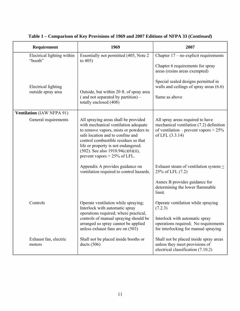
Table 1 – Comparison of Key Provisions of 1969 and 2007 Editions of NFPA 33 (Continued)
Requirement 1969 2007
Electrical lighting within “booth”
Electrical lighting outside spray area
Essentially not permitted (405, Note 2 to 405) Outside, but within 20 ft. of spray area ( and not separated by partition) – totally enclosed (408)
Chapter 17 – no explicit requirements Chapter 6 requirements for spray areas (resins areas exempted) Special sealed designs permitted in walls and ceilings of spray areas (6.6) Same as above
Ventilation (IAW NFPA 91) General requirements
All spraying areas shall be provided with mechanical ventilation adequate to remove vapors, mists or powders to safe location and to confine and control combustible residues so that life or property is not endangered. (502). See also 1910.94(c)(6)(ii), prevent vapors > 25% of LFL.
All spray areas required to have mechanical ventilation (7.2) definition of ventilation – prevent vapors > 25% of LFL (3.3.14)
Appendix A provides guidance on ventilation required to control hazards.
Exhaust steam of ventilation system < 25% of LFL (7.2) Annex B provides guidance for determining the lower flammable limit.
Controls
Operate ventilation while spraying; Interlock with automatic spray operations required; where practical, controls of manual spraying should be arranged so spray cannot be applied unless exhaust fans are on (503)
Operate ventilation while spraying (7.2.3) Interlock with automatic spray operations required; No requirements for interlocking for manual spraying
Exhaust fan, electric motors
Shall not be placed inside booths or ducts (506)
Shall not be placed inside spray areas unless they meet provisions of electrical classification (7.10.2)

12
Table 1 – Comparison of Key Provisions of 1969 and 2007 Editions of NFPA 33 (Continued)
Requirement 1969 2007
Protection General Spray finishing operations should
preferably be located in buildings protected throughout with an approved system of automatic sprinklers (701). All spraying operations involving organic peroxides and other dual component coatings shall be in approved sprinklered spray booths (NFPA 33–1401 and OSHA 1910.107(m)(1))
Spray areas must be protected by an approved automatic fire protection system (9.1). Water sprinklers, foam, carbon dioxide, dry chemical and gaseous agent systems permitted. (9.1.1) Spray application operations that involve the use of organic peroxide formulations and other plural component coatings shall be conducted in spray areas that are protected by approved automatic sprinkler systems that meet the requirements of Chapter 9 (16.2). This is exempted for resin areas by Section 16.1.
In sprinklered buildings
Rooms containing spray operations – NFPA 13, Extra Hazard Occupancy (702) Rooms of considerable area should have draft curtains (205)
Extra Hazard Group 2, except for resin areas (9.4.2, Exception No. 2) Resin application areas – Ordinary Hazard Group 2 (17.3)
In unsprinklered buildings
In dry type overspray collectors, the space within spray booth on the down stream and up stream sides of filters shall be protected with approved automatic sprinklers (305(d)). Booths and ducts should have sprinklers (706 and 707)
Section 9.1 applies

13
Table 1 – Comparison of Key Provisions of 1969 and 2007 Editions of NFPA 33 (Continued)
Requirement 1969 2007
Liquid Storage and Handling (IAW NFPA 30)
Quantity Shall be the minimum for operations; should not ordinarily exceed supply for one day or shift (602)
Basic storage requirements – storage requirements in 8.2; The quantity in a spray area limited to 60 gal (8.3.3) Specific resin requirements – liquids not to exceed greater of:
1) 1 day supply 2) 120 gal of Class IB–III
liquids in containers 3) One portable tank (660 gal)
(17.4)
Containers Open or glass containers shall not be used (604) Approved pumps for > 60 gal; otherwise, hand pumps recommended (605) Withdrawal of liquids from container shall be done in a mixing room or in spraying area when ventilation system is operating (606) Containers supplying nozzles shall be closed type or provided w/metal covers kept closed (607)
Open containers not permitted (8.5.1) Dispensing of liquids shall be done only in mixing rooms or spray areas (8.3.1). The amount of liquid in a single spray area shall not exceed 60 gal (8.3.3) Containers supply nozzles shall be closed type or provided w/metal covers kept closed (8.5.3)
14
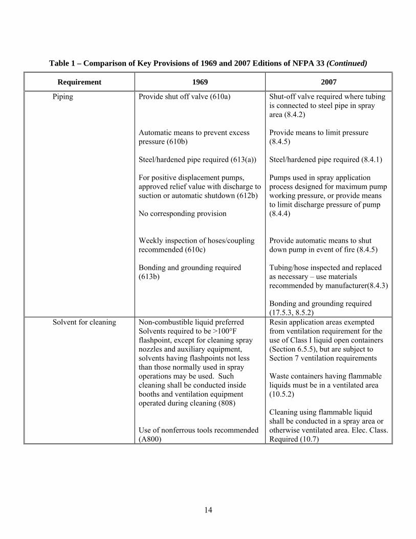
Table 1 – Comparison of Key Provisions of 1969 and 2007 Editions of NFPA 33 (Continued)
Requirement 1969 2007
Piping Provide shut off valve (610a) Automatic means to prevent excess pressure (610b) Steel/hardened pipe required (613(a)) For positive displacement pumps, approved relief value with discharge to suction or automatic shutdown (612b) No corresponding provision Weekly inspection of hoses/coupling recommended (610c) Bonding and grounding required (613b)
Shut-off valve required where tubing is connected to steel pipe in spray area (8.4.2) Provide means to limit pressure (8.4.5) Steel/hardened pipe required (8.4.1) Pumps used in spray application process designed for maximum pump working pressure, or provide means to limit discharge pressure of pump (8.4.4) Provide automatic means to shut down pump in event of fire (8.4.5) Tubing/hose inspected and replaced as necessary – use materials recommended by manufacturer(8.4.3) Bonding and grounding required (17.5.3, 8.5.2)
Solvent for cleaning Non-combustible liquid preferred Solvents required to be >100°F flashpoint, except for cleaning spray nozzles and auxiliary equipment, solvents having flashpoints not less than those normally used in spray operations may be used. Such cleaning shall be conducted inside booths and ventilation equipment operated during cleaning (808) Use of nonferrous tools recommended (A800)
Resin application areas exempted from ventilation requirement for the use of Class I liquid open containers (Section 6.5.5), but are subject to Section 7 ventilation requirements Waste containers having flammable liquids must be in a ventilated area (10.5.2) Cleaning using flammable liquid shall be conducted in a spray area or otherwise ventilated area. Elec. Class. Required (10.7)

15
Table 1 – Comparison of Key Provisions of 1969 and 2007 Editions of NFPA 33 (Continued)
Requirement 1969 2007
Prevention of Ignition Sources Bonding and grounding
Pipes Required (613b) Electrical grounding required for all metal parts of resin application areas, exhaust ducts, ventilations, spray application equipment, workpieces, or containers that receive sprays, and liquid piping. (17.5.3, and 8.4.1)
Containers where there is liquid transfer
Required (613b) Required (8.5.2)
Booths Required All parts of spray booths, exhaust ducts, and liquid piping systems, grounding required (410)
Required (17.5.3)
Space heating appliances/hot surfaces
Not permitted in spraying area subject to deposits of combustible residue (403)
Not permitted in resin application areas subject to deposits (17.5.4)
Open flame or spark producing equipment
Not permitted in any spraying area, nor within 20 feet unless separated by partition (402)
Utilization equipment not subject to deposits – NFPA 70 ordinary hazard locations (17.5.1); resin areas exempted from 6.2.5 and 6.2.6
Movement of powered vehicles
No explicit requirement in NFPA 33 or 1910.107 (see OSHA 1910.178(c)(2)(iv))
Not permitted in spray area unless spray operation is stopped and ventilation is on, with exception for listed vehicles (5.4)
No-smoking signs Required in spraying areas and paint storage room (811)
Required in spraying areas and paint storage room (10.11)
Welding Not permitted unless supervised – welding signs required in spraying areas and paint storage rooms (812) No requirement for written welding permit.
Not permitted unless authorized – welding signs not required. Written welding permit required. (10.12)
16
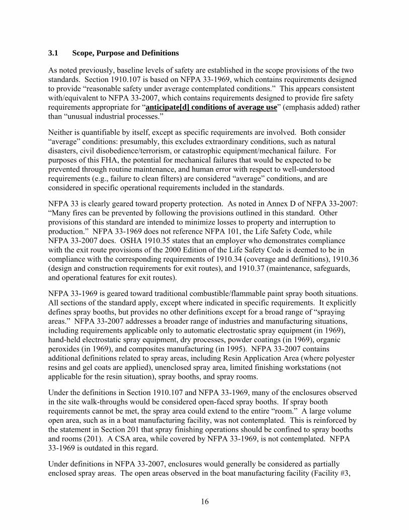
3.1 Scope, Purpose and Definitions
As noted previously, baseline levels of safety are established in the scope provisions of the two standards. Section 1910.107 is based on NFPA 33-1969, which contains requirements designed to provide “reasonable safety under average contemplated conditions.” This appears consistent with/equivalent to NFPA 33-2007, which contains requirements designed to provide fire safety requirements appropriate for “anticipate[d] conditions of average use” (emphasis added) rather than “unusual industrial processes.”
Neither is quantifiable by itself, except as specific requirements are involved. Both consider “average” conditions: presumably, this excludes extraordinary conditions, such as natural disasters, civil disobedience/terrorism, or catastrophic equipment/mechanical failure. For purposes of this FHA, the potential for mechanical failures that would be expected to be prevented through routine maintenance, and human error with respect to well-understood requirements (e.g., failure to clean filters) are considered “average” conditions, and are considered in specific operational requirements included in the standards.
NFPA 33 is clearly geared toward property protection. As noted in Annex D of NFPA 33-2007: “Many fires can be prevented by following the provisions outlined in this standard. Other provisions of this standard are intended to minimize losses to property and interruption to production.” NFPA 33-1969 does not reference NFPA 101, the Life Safety Code, while NFPA 33-2007 does. OSHA 1910.35 states that an employer who demonstrates compliance with the exit route provisions of the 2000 Edition of the Life Safety Code is deemed to be in compliance with the corresponding requirements of 1910.34 (coverage and definitions), 1910.36 (design and construction requirements for exit routes), and 1910.37 (maintenance, safeguards, and operational features for exit routes).
NFPA 33-1969 is geared toward traditional combustible/flammable paint spray booth situations. All sections of the standard apply, except where indicated in specific requirements. It explicitly defines spray booths, but provides no other definitions except for a broad range of “spraying areas.” NFPA 33-2007 addresses a broader range of industries and manufacturing situations, including requirements applicable only to automatic electrostatic spray equipment (in 1969), hand-held electrostatic spray equipment, dry processes, powder coatings (in 1969), organic peroxides (in 1969), and composites manufacturing (in 1995). NFPA 33-2007 contains additional definitions related to spray areas, including Resin Application Area (where polyester resins and gel coats are applied), unenclosed spray area, limited finishing workstations (not applicable for the resin situation), spray booths, and spray rooms.
Under the definitions in Section 1910.107 and NFPA 33-1969, many of the enclosures observed in the site walk-throughs would be considered open-faced spray booths. If spray booth requirements cannot be met, the spray area could extend to the entire “room.” A large volume open area, such as in a boat manufacturing facility, was not contemplated. This is reinforced by the statement in Section 201 that spray finishing operations should be confined to spray booths and rooms (201). A CSA area, while covered by NFPA 33-1969, is not contemplated. NFPA 33-1969 is outdated in this regard.
Under definitions in NFPA 33-2007, enclosures would generally be considered as partially enclosed spray areas. The open areas observed in the boat manufacturing facility (Facility #3,
17
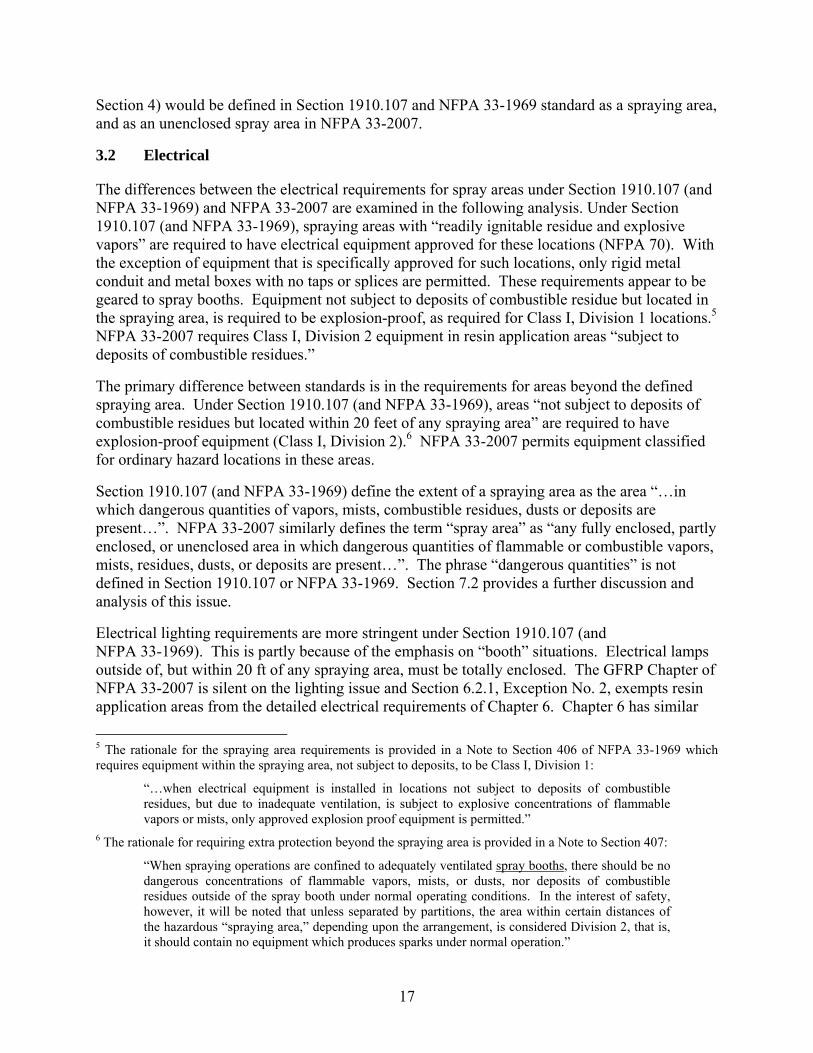
Section 4) would be defined in Section 1910.107 and NFPA 33-1969 standard as a spraying area, and as an unenclosed spray area in NFPA 33-2007.
3.2 Electrical
The differences between the electrical requirements for spray areas under Section 1910.107 (and NFPA 33-1969) and NFPA 33-2007 are examined in the following analysis. Under Section 1910.107 (and NFPA 33-1969), spraying areas with “readily ignitable residue and explosive vapors” are required to have electrical equipment approved for these locations (NFPA 70). With the exception of equipment that is specifically approved for such locations, only rigid metal conduit and metal boxes with no taps or splices are permitted. These requirements appear to be geared to spray booths. Equipment not subject to deposits of combustible residue but located in the spraying area, is required to be explosion-proof, as required for Class I, Division 1 locations.5 NFPA 33-2007 requires Class I, Division 2 equipment in resin application areas “subject to deposits of combustible residues.”
The primary difference between standards is in the requirements for areas beyond the defined spraying area. Under Section 1910.107 (and NFPA 33-1969), areas “not subject to deposits of combustible residues but located within 20 feet of any spraying area” are required to have explosion-proof equipment (Class I, Division 2).6 NFPA 33-2007 permits equipment classified for ordinary hazard locations in these areas.
Section 1910.107 (and NFPA 33-1969) define the extent of a spraying area as the area “…in which dangerous quantities of vapors, mists, combustible residues, dusts or deposits are present…”. NFPA 33-2007 similarly defines the term “spray area” as “any fully enclosed, partly enclosed, or unenclosed area in which dangerous quantities of flammable or combustible vapors, mists, residues, dusts, or deposits are present…”. The phrase “dangerous quantities” is not defined in Section 1910.107 or NFPA 33-1969. Section 7.2 provides a further discussion and analysis of this issue.
Electrical lighting requirements are more stringent under Section 1910.107 (and NFPA 33-1969). This is partly because of the emphasis on “booth” situations. Electrical lamps outside of, but within 20 ft of any spraying area, must be totally enclosed. The GFRP Chapter of NFPA 33-2007 is silent on the lighting issue and Section 6.2.1, Exception No. 2, exempts resin application areas from the detailed electrical requirements of Chapter 6. Chapter 6 has similar
5 The rationale for the spraying area requirements is provided in a Note to Section 406 of NFPA 33-1969 which requires equipment within the spraying area, not subject to deposits, to be Class I, Division 1:
“…when electrical equipment is installed in locations not subject to deposits of combustible residues, but due to inadequate ventilation, is subject to explosive concentrations of flammable vapors or mists, only approved explosion proof equipment is permitted.”
6 The rationale for requiring extra protection beyond the spraying area is provided in a Note to Section 407:
“When spraying operations are confined to adequately ventilated spray booths, there should be no dangerous concentrations of flammable vapors, mists, or dusts, nor deposits of combustible residues outside of the spray booth under normal operating conditions. In the interest of safety, however, it will be noted that unless separated by partitions, the area within certain distances of the hazardous “spraying area,” depending upon the arrangement, is considered Division 2, that is, it should contain no equipment which produces sparks under normal operation.”
18
“enclosed” lighting requirements (6.2.6), but requires “utilization” equipment “located above or adjacent to the spray area or the surrounding Division 2 or Zone 2 areas…” to be enclosed. A twenty foot requirement is not specifically invoked. Special sealed ceiling or wall-mounted lighting fixtures are permitted in spray areas by Section 6.6.
3.3 Ventilation
The differences between the ventilation requirements for spray areas under Section 1910.107 (and NFPA 33-1969) and NFPA 33-2007 are examined in the following analysis. A key attribute of NFPA 33 is the requirement of ventilation to control spray and vapor. Both 1910.107 (and NFPA 33-1969) and NFPA 33-2007 require spray areas to have mechanical ventilation. Both standards provide general requirements to control vapors, and the appendix to NFPA 33 contains guidelines to supplement the general ventilation requirements.
Section 1910.107 (and NFPA 33-1969) state that all spraying areas shall be provided with mechanical ventilation adequate to remove flammable vapors, mists, or powders to a safe location and to confine and control combustible residues so that life is not endangered. Mechanical ventilation shall be kept in operation at all times while spraying operations are being conducted and for a sufficient time thereafter to allow vapors from drying coated articles and drying finishing material residue to be exhausted. The NFPA 33-2007 definition of “ventilation” requires air movement that is sufficient to prevent accumulations of vapor-air mixtures in concentrations over 25% of the lower flammable limit (LFL). There are also explicit requirements limiting the concentration of vapors and mists in the ventilation exhaust stream to be no greater than 25% of the LFL (7.2). The explicit performance requirement in NFPA 33-2007 is to limit vapors in the spray area to ≤ 25% of the LFL. This might be considered implicit in 1910.107 (and NFPA 33-1969), but is not stated in these sections. It is explicitly included in 1910.94, which covers ventilation criteria. While an old version of NFPA 91 Standard Installation of Blower and Exhaust Systems for Dust, Stock, and Vapor Removal or Conveying (1969 Edition) is referenced in 1910.107, there is amending criteria related to the LEL. Section 1910.94(c)(6)(ii) related to spray finishing requires the total air volume exhausted through a spray booth to dilute vapor to at least 25 percent of the LEL of the solvent being sprayed.
An official OSHA interpretation to a question related to required air flows in ventilation serving spray areas references the 25% LFL limitation in the exhaust air stream [4]. The OSHA position is that the 25% LFL limitation applies to spray areas.7
Where spraying is automatically controlled without an attendant constantly on duty, the NFPA standards require the ventilation system to be interlocked to operate when there is spray operations. This is not required in 1910.107.
7 Both NFPA 33-2007, and NFPA 33-1969, give an example for calculating the evolution of 1% solvent in air, noting that this is well below the LFL for most solvents. It is noted that, when liquids are sprayed, the area in the direct path of the spray will exceed the lower flammable limit. It is generally thought that pockets of more concentrated vapors can be created. Because of this, a safety factor of 4:1 has traditionally been used. OSHA 1910.94(c)(6)(ii) provides estimates of air volumes required to keep vapors below 25% of the LEL. It appears that this approach is conservative with respect to resin applications (see discussion in Section 7.0).

19
3.4 Liquid Handling and Storage
The differences between the flammable liquid storage and handling requirements for spray areas under Section 1910.107 (and NFPA 33-1969) and NFPA 33-2007 are examined in the following analysis. Section 1910.107 (and NFPA 33-1969) limit the quantity of flammable liquid to be stored in the spray area to the minimum required for operations8 (which is interpreted to mean an adequate “supply for one day or shift”). In contrast, NFPA 33-2007 specifies maximum quantities. The resin operations area quantity in NFPA 33-2007 is similar to Chapter 7 Operations requirements embodied in the current Edition of NFPA 30 [5].
Under Section 1910.107 (and NFPA 33-1969), this storage is required to be in a mixing room or in a spraying area with the ventilation system operating. Under NFPA 33-2007, it is not clear how or whether this storage should be separated; there is a 60-gallon limit (higher than the resin storage limits) for flammable liquid-use in spray areas, and liquids are to be dispensed in spraying areas or mixing rooms. The resin storage allowance does not specify that the storage be in a spraying area.
Other handling and pumping requirements are similar in terms of keeping containers sealed and providing for pump pressure relief. There are more stringent requirements in NFPA 33-2007. It requires hardened piping (resisting fire and mechanical damage) between storage and spray areas. Tubing or hose is permitted in spray areas, provided there is an automatic means of shutdown in the event of a fire (described in the Appendix as a tie-in to the building fire alarm or suppression system. NFPA 33-1969 did not include these explicit piping/automatic shutdown requirements.
Section 1910.107 (and NFPA 33-1969) regulates cleaning solvents as follows:
“Cleaning solvents.” The use of solvents for cleaning operations shall be restricted to those having flashpoints not less than 100 deg. F.; however, for cleaning spray nozzles and auxiliary equipment, solvents having flashpoints not less than those normally used in spray operations may be used. Such cleaning shall be conducted inside spray booths and ventilating equipment operated during cleaning.
Solvent cleaning requirements in the 1969 Edition could be interpreted as being more stringent than the 2007 Edition. It could be interpreted that acetone would not be permitted, since a solvent having a flashpoint lower than liquids normally used in the spray area are not permitted (again, spray booths are anticipated) (1910.107g (5), NFPA 33-1969, 808). Resin area applications are exempted in NFPA 33-2007 from Chapter 6 Electrical/Ignition requirements which limit Class I liquid open containers, spray gun cleaners, etc., to be located in ventilated areas. This is, however, covered in NFPA 33-2007 in maintenance and operations requirements. Section 10.7.3 requires cleaning operations involving Class I and II liquids to be conducted in ventilated areas. Such areas must also meet the electrical classification requirements of Section 6.5.5.
8 1910.107(e)(2).
20
3.5 Protection
Both Sections 1910.107 (and NFPA 33-1969) and NFPA 33-2007 require that the spray area be protected by an approved automatic extinguishing system. NFPA 33 1969 indicates that operations should preferably be located in sprinklered buildings.9 In sprinklered buildings, the automatic sprinkler system in rooms containing spray applications must meet NFPA 13 Extra Hazard Occupancy design requirements. In unsprinklered buildings, where sprinklers are installed only to protect spray areas, the installation must conform “to such standards insofar as they may be applicable.” While one might interpret that requirement to mean that any sprinklered spray area, particularly an open spray area, must be protected using Extra Hazard Occupancy design requirements, this is not explicitly required by the standard. Section 1910.107 (and NFPA 33-1969) do not establish a firm level of protection:
1. A facility is not required to have total building sprinkler protection; and
2. The level/design criteria for water sprinkler protection for the spray area are not explicitly established except for buildings which are totally sprinklered. Where sprinklers are installed to protect spraying areas only, water supply from the domestic supply is permitted (705).
3. The only required protection is that dry-type overspray collectors (exhaust filters) be protected on the downstream and upstream side by approved sprinklers (305 9d).
The protection criteria is further confused by the criteria for organic peroxides. Both NFPA 33-1969 and OSHA 1910.107(m)(1) require these operations to be performed in “approved sprinklered spray booths.” The implication is that the operation will be performed in a booth. NFPA 33-2007, Section 16.2, requires operations that use organic peroxides be conducted in spray areas that are protected by approved automatic sprinkler systems. However, Section 16.1 specifically notes that the Chapter 16 requirements for organic peroxides applies except as covered in Chapter 17. Chapter 17 protection criteria therefore apply.
NFPA 33-2007 requires spray area protection and recognizes alternative methods. Spray applications are not required to be in fully-sprinklered buildings. In sprinklered buildings, protection must be designed for Extra Hazard Group 2 occupancies, except for resin areas. Resin operation areas are permitted to be protected using Ordinary Hazard Group 2 (e.g., 0.20 gpm/sq ft over 1500 sq ft or 0.15 gpm sq ft over 4000 sq ft). While NFPA 33-2007 does not require spray application areas to be in fully-sprinklered buildings, it does now require
9 1910.107 (f) does not include the “should” language, but also does not include the level of advisory detail that is in NFPA 33-1969. 1910.107 (f)(1):
“Conformance. In sprinklered buildings, the automatic sprinkler system in rooms containing spray finishing operations shall conform to the requirements of Sec. 1910.159. In unsprinklered buildings where sprinklers are installed only to protect spraying areas, the installation shall conform to such standards in so far as they are applicable. Sprinkler heads shall be located as to provide water distribution throughout the entire booth.”
1910.107(m)(1) regarding organic peroxides and dual component coatings also includes similar language:
“Conformance. All spraying operations involving the use of organic peroxides and other dual component coatings shall be conducted in approved sprinkler spray booths.”

21
that sprinklered spray areas, other than resin areas, be designed for Extra Hazard Group 2 protection.
The issue of establishing performance-based protection criteria is further complicated by changes in NFPA 13 since 1969. NFPA 13-1969 only recognized pipe schedule sprinkler design. Technology has evolved to permit hydraulically-designed automatic water sprinkler systems. A one-to-one comparison between NFPA 13-1969 and NFPA 13-2007 Extra Hazard Occupancy requirements cannot be made. It is generally considered that pipe schedule systems, by their very nature of specifying the pipe diameters, result in greater application rates and water supply compared to hydraulically calculated systems. NFPA 13-2007 reflects the current state of the art in that area.
3.6 Prevention of Ignition Sources
The requirements related to prevention of ignition sources in Section 1910.107 (and NFPA 33-1969) are similar to their counterparts in NFPA 33-2007.
3.7 Summary of Comparison
The level of protective measures required by Section 1910.107 (and NFPA 33-1969) and their counterparts in NFPA 33-2007 can be summarized as follows:
1. For similar (spray and non-spray) areas, electrical classification requirements are more stringent in Section 1910.107 (and NFPA 33-1969) than in NFPA 33-2007. Similarly, electrical lighting requirements are more stringent in Sections 1910.107 (and NFPA 33-1969) than in NFPA 33-2007, at least in part because paint spray booths are anticipated.
2. Ventilation requirements are quantified (on a performance basis) in NFPA 33-2007 as maintenance of vapor air mixtures at or below 25% of the LFL. Sections 1910.107 (and NFPA 33-1969) do not explicitly require this. OSHA Section 1910.94 on ventilation does reference the 25% requirement.
3. Liquid storage is not quantified in Section 1910.107 (and NFPA 33-1969). Liquid storage is explicitly defined in NFPA 33-2007. Location and storage of liquid is required to be in a mixing room or spray area in Section 1910.107 (and NFPA 33-1969). Resin storage is not required to be in a spray area or ventilated area (although there is an apparent conflict in requirements).
4. An aspect of resin piping and pumping is more stringent in NFPA 33-2007. This relates to automatic pump shutdown in the event of a fire. This last requirement is not clearly quantified.
5. Solvent use is more stringent in the 1969 Edition – it could be interpreted as not allowing the use of acetone in resin application areas. The basis of this is unclear.
NFPA 33-2007 provides greater detail and definitions of spray areas, more reflective of actual industry practices. In particular, Sections 1910.107 (and NFPA 33-1969) is geared more toward traditional, enclosed spray booths or dedicated rooms. It appears that large manufacturing areas were not anticipated. This is particularly reflected in
22
the electrical and sprinkler protection requirements, which anticipate the use of spray booths.
6. Neither Sections 1910.107 (and NFPA 33-1969) nor NFPA 33-2007 requires spray application areas to be in fully sprinklered buildings. Section 1910.107 (and NFPA 33-1969) does not explicitly establish protection requirements for spray areas; only that, in sprinklered buildings, the spray area be of an extra hazard design. Spray booths using organic peroxides must be sprinklered. NFPA 33-2007 recognizes many different options for spray area protection. Resin operation areas may be protected by Ordinary Hazard Group 2 sprinkler protection. Even for extra hazard design requirements, it is difficult to compare Sections 1910.107 (and NFPA 33-1969) with NFPA 33-2007 since NFPA 13 sprinkler design methods have changed.
NFPA 33-2007 requires automatic spray application pump shut-down in the event of fire.
7. Residue clean-up – NFPA 33-2007 provides specific residue clean-up requirements for resin overspray.
4.0 SUMMARY OF WALKDOWNS
During the week of April 16–20, 2007, site walk-throughs were performed of representative manufacturing facilities conducting open molding spray-up and hand lay-up applications. Five facilities were observed, designated as Facilities #1 to #5. Four facilities had these types of operations; a fifth facility (Facility #4) used cast molding which did not involve spray operations. This facility is not included in the descriptions below. The focus was on the spray operations.
Appendix A of this report documents in further detail the findings and observations from the site walk-throughs. The following provides a summary of the findings.
4.1 General Facility Information
4.1.1 Facility Manufacturing
Operations observed included gel coating of shower and sinks (no chopped fiber application), and open molding of motor vehicle parts, housings, watercraft and boats. In all four facilities, operations were conducted in partially enclosed spray areas, some similar to paint spray booths. Additionally, Facility #3 (boat manufacturing) had totally unenclosed resin spray areas.10
Building areas ranged from 20,000 sq ft to 600,000 sq ft. All buildings but one were unprotected, non-combustible construction (bare steel frame). Facility #5 had wood roof trusses and would be classified as unprotected ordinary construction. Most buildings had manual fire alarm systems, and egress appeared to be adequate (limited or no dead ends, exit travel distance within 75–200 ft).
10 The use of large unenclosed resin spray areas is also found in the manufacturing of such non-boat composite products as tanks , truck components, and rail car components.

23
4.1.2 Fire Suppression Systems
All spray enclosures had some type of automatic fire suppression system. Four enclosures observed had sprinklers; a fifth had thermally actuated, self-contained dry chemical units installed at the ceiling. Three buildings had total area ceiling sprinkler protection; a fourth did not. Table 2 summarizes the protection observed.
Table 2. Automatic Fire Suppression Systems Observed in Walkdowns
Enclosure Sprinklers Building Ceiling Sprinklers
Facility # Ceiling Plenum Duct ft) (sq area designft gpm/sq
1 Yes –tapped from overhead
ND1 – likely yes
Yes –tapped from overhead
0.21/1500
2 Yes Yes Yes 0.38/3000
Not applicable See Note 2
–– ND – did not appear to be
0.30/5000
Not applicable
–– ND Yes – ND
3 Open Area #1
Open Area #2
Partially enclosed Area #3
Yes, ceiling sprinkler system (ceiling was the roof structure)
Not Applicable
ND – did not appear to be
Yes – ND
5 No sprinklers – self-contained dry chemical units
No protection readily apparent
No protection readily apparent
No
Note 1: ND – Not determined. Note 2: See detailed notes – some small areas, probably enclosures not observed, had high hazard sprinkler
protection. 4.2 Chemicals
The chemicals used are summarized in Table 3. Styrene content of the laminate resin (used with chopped fiber) ranged from 27–35 percent.11 Gel coat styrene content ranged from 24–42 percent. Additives included methyl methacrylate (MMA). This was used in gel coats at 3–5 percent, raising overall gel coat volatile content. Maximum volatile content of a gel coat was reported to be 42% (Facility #1, based on MSDS styrene monomer content). Pure styrene has a reported closed-cup flashpoint of 88°F. Unpublished open-cup flashpoint data of actual
11 All percentages are on a weight basis

24
polyester resin material indicated that the flashpoint of the composite resin is within the range of pure styrene.
Table 3. Summary of Resins Used in Spray Applications
Facility Gel coat/
laminating resin
Discharge Rate
(gpm of resin)
Styrene Content (% by
weight)
Vapor Pressure
(mm Hg)
Other Volatile
Ingredients (% by
weight)
Vapor Pressure (mm Hg)
Catalyst
1 Gel – white 0.22–0.33 31.9 4.5 @ 68°F
Methyl Methacrylate
(5)
29 @ 68°F
MEKP
1 Gel – clear NR,* (similar to
white)
42 (mixture 48–58%)
NR –– –– Norex® MEKP-9H
2 Gel – white 0.25 (2.4lbs/min)
24–27 NR 3–4 35 @ 68°F
MEKP
2 Laminating Resin
1.6 (14lbs/min)**
27 4.3 Alpha Methyl Styrene 2***
NR MEKP
3 Laminating Resin
1–2 34.2 NR –– –– Akzo Nobel Trigonox
3 Laminating Resin
NR 31.5 NR –– –– Akzo Nobel CA DOX D50
3 Gel NR 25.3 NR Methyl Methacrylate
(3)
NR MEKP
4 Not applicable – casting operation
5 Gel < 1 27 NR Methyl Methacrylate
(4)
NR MEKP
5 Laminating Resin
NR, likely > 1
29 4.3 @ 68°F
Alpha Methyl Styrene 2***
NR MEKP
*NR – Not reported **Flows for automated spray equipment were not reviewed.
***May be counted as a component of the styrene.
25
Methyl ethyl ketone peroxide (MEKP) was used as a catalyst at all facilities, proportioned into the polyester resin stream at the pump station. Acetone for clean-up was observed at all facilities. The detailed notes and Table A-1 in Appendix A provide additional chemical details.
4.3 Resin Application Areas
Resin application areas observed in the walkdowns can be generalized into two categories: those with and without enclosures. Attributes of the resin application areas are summarized in Table 4. The enclosures observed were similar but not exactly like general spray booths. None were totally enclosed; the resin spray areas would be categorized as partially enclosed. The smallest area, in Facility #2, was a roughly 120 sq ft, 8 ft high, metallic enclosure with just the front open. It was very similar to a paint spray booth. Enclosures in Facilities #2, #3, and #5 were much bigger, ranging in area from 625 to over 1375 sq ft. The enclosing walls in the Facility #3 enclosure extended to the roof (i.e., the building roof was the top of the enclosure). The other units had ceiling assemblies 12–16 ft high.
All facilities using spray applications had dedicated ventilation systems designed to sweep the resin application area.
4.4 Application Equipment
4.4.1 Pump and Spray Gun
All equipment and operations observed, with one possible exception, would be characterized as pneumatic air-atomized spray gun systems. Unsaturated polyester resin, taken from a local drum/tote or from a piped centralized resin supply system, was pumped at local stations using pneumatic pumps. Where there were localized resin containers, air-powered mixer/stirrer equipment (using integral drum top/stirrer equipment) was observed in several cases. In one case the resin was heated before application to reduce viscosity. The local stations were in proximity to the resin application areas, either directly adjacent or within 50 feet. In Facility #3, pump stations were located near the spray area (Areas #1 and #2) or within the enclosure (Area #3). Pump operating pressures on the order of 30 psi were observed; the units had step-up ratios on the order of 11–15:1, so that resulting gun nozzle operating pressures were typically on the order of 300–600 psi.
At the local pump stations, catalyst was injected into the resin stream at a rate on the order of 2% of resin flow. All catalyst observed was methyl ethyl ketone peroxide (MEKP), either dyed (red) or clear. MEKP plastic containers at the pump stations were on the order of two-gallon capacity.
Several of the pump stations had bypass arrangements so that acetone could be pumped through spray systems for clean-up. These “flush” systems used acetone supplied from a drum or smaller container at the pump station.
Spray guns used included gel coat (resin spray only) and “chopper” guns, which discharged resin combined with glass fiber. Exact resin flow rates were not easily determined. Most personnel were familiar with the amount of resin used per week, or familiar with mass flow rates. Through interviews, the resin flow rates shown in Table 3 were established. The typical flow rates were on the order of 0.2–2 gpm, with most less than, or equal to, 1.5 gpm.

26
Table 4. Characterization of Resin Application Areas Observed in Walkdowns
Overspray Observed (Photo Reference)
Facility
Approx. Area of Enclosure
(sq ft) Walls (above
floor level) Floor Open Face Floor Outside
Area
Facility #1 Partial Enclosure
120 One side, up to about 4 ft
On floor within enclosure (1-10)
Very slight overspray (1-3)
Essentially none (1-10)
Facility #2 Partial Enclosure
1500 Most spray 2–3 ft, max height approx. 6 ft (2-11)
On floor within enclosure (2-11)
Some spray on boxes ≈ 2 ft outside (2-12); Minor over-spray on front face (2-13)
Very little – maybe 1 ft (2-9, 2-12)
Area bounded by wall and floor paper >1375
4–5 ft (3-1)
On floor protected by paper (3-2)
Slight overspray at wall edge (3-7)
8–10 ft (3-11, 3-12)
One-half area between columns 1250; Area of boat mold ≈ 20–25 ft x 10 ft
Not Applicable
Modest overspray on floor 2–4 ft from mold (3-18) plus at wash stations (3-17)
Not Applicable
Difficult to define “outside area” (3-14, 3-15, 3-18, 3-20)
Facility #3 Unenclosed Spray Area #1
Unenclosed Spray Area #2 Partial Enclosure #3
1250 3–6 ft (3-25)
On floor within enclosure (3-26)
Modest overspray on column face (3-28)
Minor spray outside, 3–5 ft (3-26)
625
4–5 ft (5-1, 5-8)
On floor within enclosure (5-8)
Yes (5-3, 5-8)
2–4 ft (5-8)
Facility #5 Partial Enclosure #1 Partial Enclosure #2
625 6–10 ft (5-13)
On floor within enclosure (5-13)
Yes (5-10)
5–10 ft (5-13, 5-14) Clean-up area (5-10)
27
One facility reported that resin would not flow in the system unless the dead-man trigger on the spray gun was depressed for operation. Another facility indicated that their system remained pressurized while the system was charged with air via the pump system.
As noted, all spray guns observed were characterized as air-atomized spraying equipment. In one situation, the discharge had a more “streaming” flow characteristic (see Appendix A, Facility #3, Figure 3-14).
4.4.2 Grounding of Equipment
Grounding of equipment was obviously taken very seriously at all facilities. While the exact nature and complete path could not always be established, there were indications of equipment grounding at all facilities. This included guns, pumps, and containers. It was reported that “chopper” guns would quickly foul if they were not grounded.
Static was identified as a troublesome issue at one facility, to the extent that water misting was sometimes used to humidify the air. Grounding, while just generally observed, was found to have limitations in several situations. In two situations, it was not clear if or how the gun was grounded. In another situation, a grounding clamp to a resin drum was inadvertently disconnected.
4.4.3 Clean-up
All facilities were observed to have acetone clean-up stations (usually small circular safety containers) either within the resin application area or at, or near, the face of the enclosure. Additionally, several facilities used acetone flush bypass systems to clean supply tubing and nozzles. It has been reported that some facilities use a separate acetone supply line to the spray gun, for clean-up operations. While not specifically observed, the acetone was evidently discharged into buckets, containers, or pans of varying design (e.g., ranging from safety can to open pan). Again, all of these were observed to be within or near the resin application area.
4.5 Ventilation System
All facilities had dedicated ventilation systems associated with the spray operations. Personnel were queried about specific designs, but design details (flow rates, velocities) could not be established. Some facilities specifically noted that they test for volatile limits under health regulations, so that ventilation must be established. It was clear in all facilities that ventilation design measures where in place to specifically control spray vapor. All facilities had dedicated exhaust systems with some type of upstream plenum. These systems discharged directly to the outside. All but one facility had dedicated make-up air capability to supply the resin application area. All exhaust plenum areas were covered with filter material, usually fiberglass. Most filters looked essentially new and clean; in no case did they appear overly clogged. They were replaced on an as-needed basis, and that maintenance methodology appeared to be working adequately.
All ventilation systems were manually operated – no automatic interlocks between the ventilation system and the resin pumping system were reported.
Exhaust ventilation electrical equipment could not be investigated in detail due to access limitations. Electrical systems (e.g., fan motors) generally appeared to be outside the duct rather
28
than in-line. In two facilities, plenum and ducts were obviously or reportedly protected by suppression systems; in the other cases, it was not clear.
4.6 Overspray
The areas of overspray are summarized in Table 4.
4.6.1 Enclosures
All enclosures had overspray on the floors and walls. The floor overspray patterns matched the molds being sprayed. Typically, the overspray on the walls was on the order of 3–6 feet above the floor, sometimes a little higher. Overspray was usually observed at the front open face. This was usually a modest amount, unless clean-up stations were located in the vicinity. Overspray on the floor outside the open face varied from essentially none (Facility #1) to 5–10 feet for a laminate spray operation (Facility #5, Area #2).
4.6.2 Open Areas
Overspray was observed essentially in a footprint (e.g., 2–4 feet) around the mold being sprayed. Clean-up areas also exhibited overspray. The resin application area is therefore the area where molds are sprayed plus a small area around the footprint of the mold, plus clean-up areas.
4.7 Electrical Equipment
4.7.1 Within Partial Enclosures
All partial enclosures had lighting which (visually) appeared to be designed for classified area. Sealed overhead lighting in Facility #3 at the roof level was reported to be non-classified, but lower-level lighting did appear to be classified. Several situations were observed in partial enclosures where there appeared to be non-classified electrical equipment:
a. Facility #2 – clock (possibly battery-operated).
b. Facility #3 – overhead crane motor.
c. Facility #5 – an electronic flow control display was installed near the face of the enclosure.
Within the open spray areas of Facility #3, there were no apparent restrictions on electrical equipment. In Area #1, no electrical equipment (except overhead lights) was observed in the area where there was overspray. There was an unclassified electrical outlet in back of the spray partition wall (Figure 3-3). In the totally open Area #2, there were a number of electrical components. An electrical control box, which looked relatively tight, was located near the wash station/application area (Figure 3-21). Electrical fans and speakers were installed on columns in the area. There was an overhead crane with an exposed electrical motor (Figure 3-15). Maintenance activities were being performed in the area as evidenced by the lift truck (Figure 3-21). It was not determined if the lift truck was a type approved for hazardous locations.

29
4.7.2 Outside Partial Enclosures
Equipment in areas immediately adjacent to enclosures was generally non-classified equipment. The degree of electrical equipment was modest, and included fans and switches. The exception was in Facility #1, where there was a classified heating unit at the pump station, immediately adjacent to the enclosure. However, an unclassified switch was located just above the heater (Figure 1-3). Other non-classified equipment observed just outside the enclosures included:
a. Facility #2 – electric fans, controls and outlets observed on face (Figure 2-13). Also, items of exposed electrical equipment (open mixing motor, electrical panel, 9VDC catalyst alarm) were observed in the pump station area.
b. Facility #3, Area #3 – electrical switch, control box (Figure 3-28), and speaker.
c. Facility #5 – electrical outlet at the bottom of a roof truss, approximately 10 feet from the enclosure face opening.
4.8 Chemical Storage
Laminating or gel coat resin was supplied to the pump stations either by local supply (steel 55-gal drums or 275-gal intermediate bulk containers) or piped from a central supply. As noted in Section 4.4.1, pump stations were within or immediately adjacent to the spray enclosure/mold area or within no more than 50 feet of the spray area. Except as noted in Section 4.7.2, there was no electrical equipment associated with the pump stations: all motive force for pumping and mixing was pneumatic. Where local containers were used, a closed-top assembly with pump suction opening was typically installed over top of the drum. In some cases, a tight connection was made (Figure 1-6); in other cases, a loose connection (suction tube inserted into 2.5-in. bung opening) was observed (Figure 5-2). The “openness” of resin containers is subject to question.
There were three instances in which open storage containers of acetone were observed: (1) In a pump suction tube inserted in a bung opening (Facility #2, Figure 2-14); (2) an acetone flush pail supply with a questionable seal (Facility #3, Figure 3-15); and (3) drums open for waste disposal (Facility #5, Figure 5-12).
Bulk storage areas were not specifically reviewed in detail. In low-use cases, resin and acetone storage were within the production area. Multiple (more than two) containers (drums) of resin were generally not observed. Storage of acetone generally involved more than two drums, or a pallet load, away from the spray area or pump station.
4.9 Prevention of Ignition Sources
All facilities reported that they trained their spray application personnel in ACMA-recommended overspray minimization techniques. Overspray shields were observed in a number of situations (e.g., Figure 3-11).
All facilities had no-smoking policies in the production areas. These policies appeared to be strictly enforced.
Maintenance procedures depended on the facility. In Facility #1, maintenance was performed on an on-call, as-needed basis. Operations would be shut down for required maintenance. In the
30
larger facilities (#2 and #3), maintenance would be performed near active spray or pump stations as needed. Tools used in these maintenance situations would likely be typical, unprotected equipment (i.e., not classified for hazardous locations). There was no indication that any active maintenance work would be performed within resin spray application areas while spraying was actually being performed.
5.0 FIRE HAZARD ANALYSIS
5.1 Hazards
The primary fire safety hazards result from the use and storage of flammable, combustible and reactive liquids. The principal hazards of spray operations originate from flammable or combustible liquids and their vapors or mists, and combustible residues which may be deposited in the area of operations. The flammable and combustible liquids observed included:
• Styrene resin, flashpoint ≈ 88°F
• Methyl methacrylate (MMA), flashpoint ≈ 73°F (as low as 50°F reported)
• Acetone, flashpoint ≈ -4°F
• MEKP > 200°F
The catalyst used in all situations was an organic peroxide, MEKP. This is classified as a combustible liquid, organic peroxide, unstable reactive liquid, and irritant. Chapter 16 of NFPA 33-2007, provides explicit requirements for organic peroxides.
Some resin mixtures contained cobalt material, used to accelerate curing.
5.2 Areas and Applications Where the Hazard Occurs
The following is an evaluation of the potential hazards which may occur in the spray application process. They are categorized by location and by initiation of the hazards. The locations include: spray area (as defined by 1910.107 and NFPA 33); the piping system between the spray area and local storage; and the local resin storage area. Hazards may be initiated by normal operations, or by an accident.
5.2.1 Spray Area, Including Spray Piping Equipment and Gun.
By definition, an open process exists. Vapors may exist. An option to prevent vapors is not possible.
1. Under normal operating conditions, vapors may exist from:
a. High pressure mist (spray) of resin material discharged from the spray gun;
b. Evaporation of styrene vapors from a resin used in low pressure spray/hand lay-up situation;
c. Acetone vapors emitted during clean-up where acetone is used as a flush in the spray gun piping system; and
d. Acetone vapors from an open waste storage container.

31
2. Under accidental conditions, vapors may exist from:
a. Either resin or acetone flush in the piping system, still under pressure, which ruptures/leaks due to mechanical failure of the gun/piping system. Depending on the attributes of the failure, this could result in a spray and/or spill; and
b. Inadvertent tipping/knock-over of acetone waste containers.
Venders were queried about potential discharges in the case of catastrophic failures such as a rupture or break in a hose connected to a resin pump. They were asked if there were any failsafe devices for the pumps to stop or mitigate the impact of such a failure. Information about spray gun capacity and the capacity of pumps typically associated those guns was also requested. These aspects were discussed with Binks ITW Industrial Finishing, Graco Inc., Lincoln Lubrication, Jesco Products Company, and GlasCraft.
The maximum potential flow that could occur during a rupture or break depends on the pump capacity, the hose size, distance through the hose to the rupture, and the viscosity of the material being pumped. There was a consensus that the maximum potential flow in the worst case scenario would be equivalent to the maximum capacity of the pump being used minus the friction loss in the hose up to the failure. This sentiment was expressed by the technical support agents from Jesco, Graco, and Binks. When a rupture in a hose occurs, the loss of resistance allows the pump to “runaway,” increasing the cycles per minute and flow until it reaches its maximum capacity. It will continue to pump until the supply of resin is exhausted or the pump is manually shut down.
Spray guns for industrial resin application typically operate with a flow of 0.25 to 0.50 gallons per minute (gpm). Guns of this sort include Binks’ fiber-reinforced polymer guns: LEL Resin Gun (part number 207-12200), Century LEL Resin Gun (102-3600), Century LEL Gel Coat Gun (102-3610), and Century Vinyl Ester Gun (102-2545). Tips for these guns have an area that ranges from 0.050 to 0.080 square inches for the LEL resin gun or 0.018 to 0.062 square inches for the Century guns. According to Graco and Binks, a pump attached to such a gun will typically operate at 0.50 to 0.75 gpm. Pumps associated with guns of that capacity will have a maximum capacity of 2 to 4 gpm. Pumps such as Binks’ The Boss series (part numbers 103-1778, 103-1783, 103-1786) are examples of pumps typically used with such guns. Similar rates were expressed by Graco, though specific part numbers and models were not provided.
Devices are available for both existing and new pumps to detect a rupture and act to mitigate the situation. Representatives at Binks, Graco, and Lincoln Lubrication were able to provide information on these devices (Binks’ Pump Protector model 41-11150, Lincoln Lubrication’s Power Master III pump series, and Graco’s Runaway Control Valve). Jesco stated that no failsafes currently exist for their pumps in the case of a catastrophic failure of a hose. A runaway control valve can be attached to the air supply of an existing system and operates by sensing the air flow. It will automatically shut off the air supply when there is an indication of a leak, such as an increase in air flow caused by a runaway pump or cavitations in the siphon hose caused by the pump attempting to discharge more resin than the supplying hose can provide. It was unclear how much resin could be discharged before shut off.
Some new air motors come equipped with a data tracking device that can be pre-set to only permit a pump to operate at a specific cycle rate. Graco was the only company that stated it

32
provided air motors of this sort (NXT air motor). When a cycle rate higher than the selected rate is detected, the device will turn the air supply off, stopping the pump. Graco stated that a pump capable of a 4.5 gpm flow in the worst case scenario would produce approximately 0.38 gallons in the time it would take for a motor with a data tracking device to shut it down.
Deposits of resin overspray may also occur in the resin application areas. This could involve resin which emits vapor, but begins to cure into rigid plastic waste. In areas where hand-tooling occurs, this waste build-up can be substantial (Figure 5-10). NFPA 33-2007, Section 17.7 provides specific requirements for resin use and handling. Excess catalyzed resin, while still in the liquid state, must be drained to an open-top, non-combustible container with at least two inches of water (the water floats on top of the waste resin, forming a barrier). Wall and floor surfaces must be protected with paper or polyethylene to collect overspray, which must be properly deposited in a non-combustible container. These requirements appeared to be generally followed in the facilities visited.
Otherwise, there did not appear to be sustained overspray build-up on floors, walls or exhaust filters. The excess resin is not a “combustible dust” subject to spontaneous ignition as in other spray situations anticipated by NFPA 33.
5.2.2 Piping System between the Spray and Local Storage Area/Pump Station
The piping system, which could be considered outside the spray area, is the piping from storage to the spray gun (from pumping station to spraying area). This is a normally closed process. Vapors would only be present in an accidental situation. In this case, the scenario is similar to the accidental rupture/leak described above. In most of the situations observed, the pump station was located in close proximity to the spraying area (e.g., adjacent to potential enclosures).
5.2.3 Local Storage within Spray Area (NFPA 30-2007 definition)
Local resin and catalyst storage is usually associated with the resin pump and MEKP injection station. In some situations, this includes a bypass where acetone can be flushed through the system. A local container of acetone may be provided. The following situations are present:
1. Piping – resin discharge piping (through which acetone may be flushed) terminates at the pumping station. The pump/piping is a closed system under normal operating conditions. Under accidental conditions (e.g., rupture/leak resulting from component failure or failure to secure the system during maintenance), a spray or spill may occur. Accidental situations may involve a pipe failure (e.g., due to wear) or a pump mechanical failure. The scenario is similar to that described for the other accidental pipe situations.
2. Storage
a. Normal operating conditions – for both resin and acetone storage at the pump station, the system should be “closed.” Drums should have sealed tops and totes/tanks should have fixed connections.
b. Accidental conditions – vapor may result from:
i. An unenclosed storage container, e.g., unsealed suction supply pipe;
33
ii. Mechanical failure of a pipe attached to a container, e.g., at a connection joint); and
iii. Accidental discharge of liquid, e.g., from supply piping, during routine change-out of the resin or acetone storage container.
In these situations, vapors from the container/pipe will likely result. A spill of liquid may also occur.
5.3 Mitigation of Hazards to Personnel
Section 5.2 described how spray, mist, vapor and associated deposits could occur under normal and accidental situations. The potential for fire exposure to personnel can be mitigated. These mitigation strategies, which are embodied in the Section 1910.107 and NFPA 33 requirements, include the following:
• Using non-combustible liquids, or limiting the amount of flammable liquids, e.g., using alternative materials having a lower inherent combustibility/hazard.
• Preventing ignition should hazardous vapors be present:
– Under normal use conditions; and
– Under unexpected, accidental conditions.
• Limiting the impact should ignition occur, for:
– The person(s) intimate with the incident;
– All personnel within the area/building; and
– Responding firefighters.
5.3.1 Use of Non-combustible or Limited Combustible Liquids
• Non-flammable solvents for clean-up are available
– Facility #3 is considering a change-over to non-combustible clean-up solvent for fire safety reasons;
– Non-volatile replacement solvents are reported to be less effective than acetone, so their widespread use seems unlikely; and
– Environmental regulations may push industry in this direction to lower the volatile organic compounds emitted to the atmosphere.
• There is recognition that polyester resin is not as hazardous as other low flashpoint liquids.
Styrene vapor reacts in the curing process and the non-reacted fraction evaporates off. The evaporation and vapor production mechanism of the styrene monomer is not the same as a “neat” flammable liquid. Section 7.0 provides a more detailed discussion of this process. The difference in styrene resin vapors and acetone vapors from system flushing is not clear and needs to be characterized.
34
Composite resin flammability for storage situations was investigated in a series of fire tests [6]. Based on the flashpoint of the styrene monomer, polyester resins are classified as flammable liquids (typically Class IB or IC) by NFPA 30. Flashpoint testing confirmed that the resin will “flash,” even in the stored mixture state [7]. For example, resins having styrene contents ranging from 36–48% had open-cup flashpoints ranging from 79–91°F. However, because the resin is a viscous liquid with a low vapor pressure and a high-density, it was postulated that resin stored in drums might behave more like a melted plastic than a non-miscible Class IC liquid when subjected to fire. This could enable the use of reduced fire protection system designs as compared to protection schemes ordinarily required by NFPA 30 for Class IC liquids.
A fire test program was performed to evaluate the fire performance of resin and to develop suitable fire protection criteria. This testing demonstrated that palletized storage of resin in relieving-style steel drums stacked up to three high can be adequately protected by water sprinklers discharging at a density of 0.45 gpm/sq ft. With this level of protection, the fire was controlled, pile stability was maintained, and ceiling temperatures remained well below critical levels. This level of protection is less than the 0.60gpm/sq ft required in NFPA 30 for Class IC liquid drums stored three-high in relieving-style containers.
All of the resin drums observed during the site walk-throughs used relieving-style bung closures as used in the resin drum tests.
5.3.2 Ignition Prevention
The scope of this analysis includes resin application areas, or spray areas, as previously defined. Presuming ignitable vapor is present under normal operating conditions, ignition may be prevented by eliminating potential sources, or limiting the extent of the spray/vapor area/volume. In other areas, such as storage areas, design and preventive measures are used to assure a high probability of preventing accidental release of vapors which could be ignited. This is the basic protection philosophy as embodied by Section 1910.107 and NFPA 33 requirements. For the resin application area, the following sections outline potential ignition sources and vapor-limiting approaches. The Section 1910.107 and NFPA 33-2007 requirements were presented in Section 3.0. Comparative commentary is provided on differences in performance level, and how these criteria relate to conditions observed in the walk-throughs for the possible ignition scenarios.
5.3.2.1 Ignition Sources
1. Open flames – open flames may occur through hot work, welding, or matches/smoking. These sources are limited by both design and operational requirements in Section 1910.107 and NFPA 33-2007. The operational requirements to prevent ignition sources are similar in Section 1910.107 and NFPA 33-2007 (see Table 1). OSHA 1910.178(c)(2)(iv) and NFPA 33-2007 include requirements for powered vehicles (forklift trucks). In the walk-throughs, maintenance operations were observed near resin spray operations. There was no identification of hand electric tools that were of an enclosed or non-sparking type. Limitations on maintenance activities, in terms of hot work, appeared to be strictly enforced. As a practical matter, major work could not realistically be performed without cessation of spray operations. This presumes that equipment is properly secured, depressurized,
35
and drained as needed. This could not be determined from the walk-throughs. Maintenance issues related to potential electrical sources were identified, see Section 4.7.
Uncontrolled maintenance activities would be considered a remote, but plausible ignition scenario.
All facilities observed a strict no-smoking policy. In only one facility, where there was no spray operation, was smoking in the manufacturing area cited as a potential issue. Otherwise, no-smoking policies were clearly enforced, and most facilities had proper signage to that effect. Ignition by accidental smoking/open match appears unlikely.
Although remote, one additional source is arson. Incendiarism was cited as a potential cause in one of the few identifiable fire losses (see Section 6.1).
2. Hot surfaces – Both Sections 1910.107 and NFPA 33-2007 restrict hot surfaces in areas subject to resin deposit. The facilities reviewed were essentially free of hot surfaces within or in proximity to the spray area. The exception was a gas-fired heating strip observed at Facility #5. This was located at the roof truss, and was located outside the resin spray area.
3. Sparks from mechanical sources – see also Items 1 and 4. An unlisted forklift truck in an open spray area could be an ignition source. This is addressed in OSHA 1910.178 and NFPA 33-2007. A forklift was observed in Facility #5.
4. Sparks from operations – static electricity can result from liquid flow through the gun/piping or chopped fiber stream through gun. This is addressed in both Sections 1910.107 and NFPA 33-2007. It is emphasized in Chapter 17 of NFPA 33-2007. Facilities obviously paid attention to this aspect of safety. There were two instances where grounding of equipment could not be confirmed and one where grounding was accidentally disconnected. This is a plausible ignition scenario, and is identified anecdotally as the most common fire scenario (see Section 6.3).
5. Sparks from fixed electrical equipment within spraying area – any unsealed electrical equipment (i.e., non-classified, not enclosed to prevent discharge of sparks) could provide an ignition source in the spray area. Section 1910.107 (NFPA 33-1969) might be considered more restrictive for the actual spray area, since it essentially does not permit electrical equipment where deposits may occur, and extends a level of protection beyond the “deposit” area to the rest of the spray area, and then beyond the spray area (see Section 3.2).
In partial enclosures, very little unprotected electrical equipment was observed. Generally, lighting was enclosed or conformed with the special sealing requirements in Chapter 6 of NFPA 33-2007. In larger enclosures and open areas, there were unenclosed ventilation and crane motors. The crane motors were about 20 feet above the floor. These are potential ignition sources, depending on the spread, control and volatility of vapors.
36
6. Sparks from transient electrical equipment, such as electrical tools used in spray areas or tools for cleaning or maintenance, if performed during spray operations, could be a potential ignition source. Section 1910.107 (NFPA 33-1969) explicitly states that clean-up tools should be non-ferrous materials.
Tools generally involved brushes and rollers. Metallic equipment was not specifically observed, but may have been used. Routine maintenance (running of electrical cables) was observed in an open area concurrent with resin application operations. Ignition of vapors by maintenance activities is a plausible scenario.
5.3.2.2 Limiting of Vapor Spread
Potentially hazardous conditions can be prevented by limiting the potential for vapor spread. This can be achieved through limiting the quantities of flammable flow under normal and accidental conditions, and limiting vapor spread through mechanical ventilation.
1. Limit vapor amount from spray/spill
a. Normal operations – vapor can be limited by limiting the pressure and flow characteristics of the spray operations. Since effective manufacturing is dependent on this, the limiting factor is the maximum production area flow/pressure. The characteristics observed in the walk-throughs are shown in Table 3. The hazard for any particular situation would be bounded by these characteristics.
Overspray creates a curing, plastic material. The combustibility of this material is more like a solid plastic than a combustible paint spray residue or dust. NFPA 33-2007 includes specific requirements related to resin residue/waste clean-up.
b. Accidental discharge – vapors may occur as a result of accidental discharge as noted in Section 5.5.1. The potential flow/pressure resulting from an accidental breech is not easily quantified. Systems may remain pressurized.
Resin may discharge in the spray area, piping-run to the local storage area, or in the storage area. Section 1910.107 and NFPA 33-2007 provide requirements for hardening of piping systems (resistance to physical damage and heat). Shut-off valves are required to secure potential leaking systems (e.g., where tubing is used and may be breached). NFPA 33-2007 provides an additional requirement for automatic shut-off of pumping systems in the event of a fire, tied into fire protection systems.
The facilities observed used some plastic tubing in the gun system. Shut-off valves were generally installed, although they would not be immediately obvious in some situations. Presumably, the operators were aware of shut-off procedures. No automatic shut-down of pumps was identified. Facilities did indicate that resin leaks occasionally occurred as a result of normal equipment wear and tear. A single major incident involving a resin pumping leak was identified (see Section 6.1).
37
c. Storage areas – Neither Section 1910.107 nor NFPA 33-2007 explicitly addresses local pump storage situations as observed in the walk-throughs. Provisions must be pieced together from electrical, ventilation, storage, and operation sections of the code.
Section 1910.107 and NFPA 33-2007 presume that storage areas involve closed systems. Provisions are provided to address this. In general, resin storage systems observed appeared to be closed systems. Particularly where local drums/totes were used, closed-pump piping tops or fixed-pipe connections were used. The same design was not always observed for acetone clean-up and flush systems. Small safety containers were observed in all spray areas. The majority of these appeared to be appropriate safety containers. Additionally, open containers (meaning an obvious opening or a less than complete seal) were observed in several situations in areas other than spray or mixing rooms, i.e., areas with adequate ventilation and electrical classification. This practice would not comply with either Section 1910.107 or NFPA 33-2007.
A vapor ignition could occur at the pump station/storage area. Personnel are only in this area for material change-over and maintenance. Most equipment in this area is pneumatic. However, in the walk-throughs, several situations were observed where it appeared that unclassified electrical equipment was in the pump station area. Additionally, there is a potential for improper grounding in this area where proper grounding is required. There is a plausible scenario for ignition in the pump station area (see also 6.1).
2. Limitation of Vapor by Mechanical Means
A key protection aspect of both Section 1910.107 and NFPA 33-2007 is the limitation of vapors and residues by mechanical supply and exhaust systems. Both standards require mechanical ventilation for spray areas. Neither is explicit in flow/pressure/velocity requirements to contain vapors. It is not clear that the example provided in the Appendix/Annex for calculating vapor concentration is applicable for the composite resin vapor emission characteristics. NFPA 33-2007 and OSHA 1910.94(c)(6)(ii) set an explicit requirement for vapors to be maintained at or below 25% of the LFL.
All facilities observed had mechanical ventilation in the spray operation areas. The designs could not be readily quantified. Qualitatively, air movement could generally be felt in the spray areas. Neither Section 1910.107 nor NFPA 33-2007 requires interlocks between mechanical system and manual spray operations. None were observed in the site walk-throughs. There may be situations where the ventilation flow is limited; in one situation, the fresh air supply system was not operating. In this situation, and in others by design, make-up air was provided by the facility volume and associated building openings/leakage.
Other environmental/worker safety requirements act to assure that vapors are controlled. The eight-hour time weighted average permissible exposure limit for

38
workplace exposure to styrene is 100 ppm.12 In one facility, open spray areas were monitored on a scheduled basis to assure conformance with this requirement. Additionally, the industry has promoted a controlled spraying program [3]. This is a work practice that has demonstrated effectiveness in reducing emissions from the open molding process. As a pollution-prevention method, controlled spraying minimizes emissions by increasing material transfer efficiency and reducing overspray. This is achieved by using the lowest effective spray gun pressure, training operators in gun handling techniques, and using mold flanges to minimize overspray. These processes, when implemented, help to limit overspray. Several facilities observed had clearly implemented these processes. All facilities indicated that operators had been trained in spray operations. This was mostly informal, using ACMA-supplied materials such as noted in Reference 3.
A review of OSHA regulations, as they apply to ventilation practices has identified a number of limitations in applying the 25% LEL criteria to actual manufacturing situations [9]. Some OSHA inspectors interpret a 25% LEL restriction to mean that the employer must demonstrate it maintains levels below 25% of the LEL in any room or building used for open molding using a theoretical approach or a very conservative mathematical calculation. One method compares the saturated vapor pressure of each chemical constituent present in the composite materials to 25% of the associated LEL. The LEL values for the styrene, MMA, and acetone are listed in Table A-1. In the case of saturated styrene vapor at normal room temperature (77°F or 25°C), the calculation results in the following value:
5 mmHg/760 mmHg x 1,000,000 = 6,579 ppmv
Twenty-five percent of the LEL for styrene is:
25% x 1.1% x 1,000,000 = 2,750 ppmv
Therefore, the author concluded that a saturated styrene vapor atmosphere at room temperature cannot meet the 25%-of-LEL compliance demonstration, which was considered ironic, because the calculation clearly shows that an explosive atmosphere (LEL at 11,000 ppmv) cannot form at room temperature.
§29 CFR 1910.94 Ventilation pertains to spray finishing. The definition of spray finishing operations is:
1910.94(c)(1)(i) “Spray-finishing operations.” Spray-finishing operations are employment of methods wherein organic or inorganic materials are utilized in dispersed form for deposit on surfaces to be coated, treated, or cleaned. Such methods of deposit may involve either automatic, manual or electrostatic deposition but do not include metal spraying or metallizing dipping, flow coating, roller coating, tumbling, centrifuging, or spray washing and degreasing as conducted in self-contained washing and degreasing machines or systems.
12 Also see the item “OSHA styrene agreement” at http://www.osha,gov/SLTC/styrene/recognition.html regarding the agreement between industry and OSHA to promote compliance with a voluntary PEL of 50 ppm.
39
The analysis in Reference 9 indicates that gel coat applications resemble this definition, but the characteristics of resin application do not. Spray rooms used for production spray-finishing operations must conform to spray booth requirements. Ventilation is to be provided in accordance with the provisions of 1910.107(d) (NFPA 33m 1969, Chapter 5). Velocity and air flow requirements for spray-finishing operations are specified in 1910.94(c)(6). Minimum air flow velocities range from 50–75 fpm with no cross draft for electrostatic operations to 150–250 fpm for processes with air-operated guns. A maximum cross draft of 100 fpm is specified. Whether these ranges are appropriate for a resin operations area is debatable, as described in Reference 9, but it provides the order of magnitude of air flow rates which might be involved or found in resin facilities.
5.4 Catalyst Use and Storage
Resins are initiated, or catalyzed, by the use of either methyl ethyl ketone peroxide (MEKP) or benzoyl peroxide (BPO). In all of the facilities visited, MEKP was the catalyst used. An example MSDS indicated that the methyl ethyl ketone peroxide was diluted with dimethyl phthalate (34% in this case). Sometimes, a red dye was included which is used to identify where spray has occurred, and to indicate that the catalyst was being injected. The injection rate is on the order of two percent of the resin flow.
The NFPA 704 health/fire/reactivity rating for this material is 3/2/2 or 2/2/2. It is a combustible liquid. There is a risk of reaction if heated above 80°F or from shock or friction. The liquid is an irritant and is toxic if ingested, and is corrosive to the skin and eyes.
Typically, a two-to-three gallon capacity container of MEKP was observed at each pump station. At Facilities #1 and #5, no special storage container cabinets or rooms were observed for any bulk storage of MEKP. Given the relatively low use rate, material may have been ordered on an as-needed basis. Facilities #2 and #3 had bulk chemical storage rooms located remote from the spray areas. These were not specifically viewed. In general, additional bottles of MEKP standing around the application areas/pump station were not observed. Only those bottles in use or on stand-by for use were observed at individual pump stations.
NFPA 33-2007 includes requirements for the storage and use of organic peroxides (Chapter 16). The requirements are for general use and handling of the chemical. The facilities viewed appeared to be in general compliance with the requirements. At one facility, there was some sand/dust from a nearby finishing process that left a residue at the pump station.
The language of NFPA 33-2007 is somewhat conflicting in terms of the applicability of Chapter 16 for composites manufacturing (Chapter 17). Chapter 17 notes that resin application equipment should be installed in accordance with both Chapters 17 and 16. Chapter 16 has an exemption to the scope, “Exception: As covered in Chapter 17.” To clarify this, Chapter 17 should probably be exempt entirely from Chapter 16, and provisions for organic peroxide use and storage explicitly stated in Chapter 17.
40
5.5 Mitigation Through Automatic Fire Suppression
While automatic fire suppression systems may provide some incidental benefits in protecting site workers, the requirement in Section 1910.107 and NFPA 33-2007 for automatic fire suppression does not appear to relate to personnel protection per se. Suppression systems are required in spray areas. The design requirements in Section 1910.107 and NFPA 33-2007 do not establish an explicit level of overall suppression system performance. Because the suppression systems, particularly automatic sprinklers, are thermally activated, they cannot be expected to respond quickly enough to provide protection to personnel intimate with a flash fire of vapors. Areas outside the spray area, where personnel are less likely to be intimate with a flash fire, are not required to be protected with automatic suppression systems.
Personnel not intimately involved with the initiating fire would attempt manual suppression or exit the building. The high ceiling heights, building volume, and building openness make it unlikely that a rapidly growing, unsuppressed fire (from lack of or inadequate fixed fire suppression) will make perimeter exits untenable to existing workers.
Since neither Section 1910.107 nor NFPA 33-2007 require complete automatic suppression systems, responding firefighters may face a large, uncontrollable fire (see Section 6.1). Given that the buildings are unprotected construction, building structural collapse may occur relatively quickly. A defensive firefighting strategy would be appropriate.
The application rate difference between Section 1910.107 and NFPA 33-2007 for automatic sprinkler protection of resin application areas appears to be a property protection issue which does not affect personnel safety.
NFPA 33-2007 does provide one significant level of performance improvement. Spray application liquid pump shutdown is required to automatically occur in the event of a fire.
6.0 FIRE LOSS HISTORY
6.1 NFPA Data
The National Fire Protection Association (NFPA) provided some historical fire loss data for this FHA. Their system for capturing fire incidents involving facilities covered by Section 1910.107 and NFPA 33-2007 is biased towards:
• Incidents where there are multiple fatalities or multiple serious injuries;
• Incidents that indicate problems with timely escape and evacuation from the fire area;
• Incidents where there is very large dollar loss (primarily property damage, but business interruption might also be a factor); and
• Severe/unusual fire development or explosion incidents.
Most of the “routine” industrial fires are captured by NFPA via news clipping services or by voluntary submittal of reports from the responding fire department(s), neither of which are very definitive without further investigation. Essentially, NFPA does not hear about the unknown
41
number of small fires in facilities covered by NFPA 33 that are handled by a facility’s own fire brigade or are considered minor by the responding fire department.
The following are digests of the three significant incidents identified by NFPA staff, with comments by NFPA staff, in brackets, following each:
1. WASHINGTON, JAN. 1993: Single-story facility that manufactured plastic shower doors, 35,000 sq. ft., unprotected ordinary construction, no fire protection equipment present, plant was closed at time of fire.
Investigators believe that a torch used by workers during the day to effect repairs to the roof ignited a slow-developing fire. A night-time cleaning crew discovered the fire in the wood/tar roof and called the fire department. The fire department was not able to control the fire and it spread across the entire roof. The roof eventually collapsed and spread the fire throughout the facility. Damage est.: $5,000,000. It should be emphasized that this fire did not involve any spray process or liquid storage as the primary cause of the fire. [This incident is not relevant to the issue at hand. The manufacturing equipment/process had nothing to do with ignition or subsequent fire development. Raw materials (FGRP resin, catalyst) were also not relevant to fire development. This incident could have happened anywhere in any type of manufacturing operation.]
2. MICHIGAN, June 1993: Single-story facility that manufactured automobile
bumpers, 230,000 sq. ft., unprotected noncombustible construction, no fire detection system, partially sprinklered, but no sprinklers in area of fire origin. Plant was operating at time of incident.
Investigators determined that a flammable liquid was poured between pallets of finished bumpers in an unsprinklered storage area. Fire was immediately discovered by employees and the fire department summoned. Fire spread rapidly to adjoining areas of the building via the combustible roof covering, although fire at floor level was contained. Building and contents eventually destroyed. Damage est.: $32,000,000.
Contributing factors: sprinkler system overwhelmed by fire, which had time to grow because it began in unprotected area of building; unprotected openings in the common wall between the protected and unprotected areas of the building also allowed fire spread; roof covering contributed to rapid fire spread.
[Judging by the description of fire origin, this looks like an act of incendiarism. Again, this could happen in any type of facility with the same end result. The FGRP manufacturing process and raw materials were involved AFTER the fire had gained significant headway.]
42
3. MISSOURI, Pbly. March 2004: Single-story facility that manufactured various FGRP products, metal-framed building, w/metal walls and roof, connected to another, larger building by a breezeway.
Fire began in the production area and quickly spread to FGRP finished goods, destroying the manufacturing building and damaging the connecting building. Fire was stopped from involving a large FGRP resin tank just outside the building. Fire began when employees were investigating a malfunctioning resin pump. Resin spill ignited and fire department immediately called. Fire grew too rapidly to allow employees to use nearby extinguishers. Heat and smoke prevented an interior attack by the fire department. It was not reported whether the property had sprinkler protection. One serious, four minor injuries. Damage est.: $2,000,000
[This is the only incident we could find where the FGRP resin was the first item ignited. I could not determine whether the pump was actually functioning at the time. If so, it could have been pumping raw resin into the incipient fire, causing uncontrolled and rapid fire growth. No indication of what actually ignited the resin.]
6.2 Data from NFPA 33
Annex D of NFPA 33-2007 Edition provides a review of the fire record for spray applications using flammable materials. It should be emphasized that this review is for all liquid-based coatings under the purview of NFPA 33. Composites manufacturing makes up a small fraction of those incidents, as noted in Section 6.1 above. Given this much broader category of facilities and hazards, the following information is provided from 250 fires involving spray application of liquid-based coatings.
Where provisions of NFPA 33 were followed, a typical spray booth fire was confined to the booth, plenum, and exhaust system. A typical fire starting in the work area of the booth spreads across overspray deposits to the plenum and exhaust duct. A fire starting in the exhaust duct spreads across overspray deposits to the plenum and booth work area. All sprinklers in the booth, plenum, and exhaust duct usually operate to control the fire. One or more sprinklers outside the booth might operate, depending on quantity of overspray residue. Final extinguishment generally is by small hose or portable extinguishers.
The leading causes of fire in conventional systems included the following:
1. Use of spark-producing equipment such as cutting, welding, and grinding near the spray area;
2. Friction, caused in most cases by overheated bearings on the exhaust fan shaft or by rubbing of exhaust fan blades against overspray deposits on walls of the exhaust duct;
3. Arcing electrical equipment;
4. Spontaneous ignition; and
5. Discharge of static electricity.
43
The leading causes of fire in electrostatic paint spray operations included the following:
1. Underground or improperly grounded objects in the spray area;
2. Failure to fully de-energize equipment before cleaning;
3. Pinhole leaks in the paint hose to the spray gun; and
4. Other causes similar to nonelectrostatic systems, such as smoking and cutting and welding.
Thirty-five of the 250 losses exceeded $100,000 combined property damage and business interruption. It was determined that failure to follow one or more of the basic provisions of NFPA 33 was the reason for the large losses in all cases. The most frequently identified deficiencies were the following:
1. Lack of complete automatic sprinkler protection. Either no protection was provided or protection was lacking or ineffective in part of the spray area. Normally this was due to lack of protection or sprinkler heads coated with overspray in exhaust ducts or plenum;
2. Inadequate cutoff between spraying operations and the rest of the plant; and
3. Poor maintenance with excessive buildup of overspray. Failure to keep areas outside booths free of overspray residue has resulted in fire spread between booths. Overspray residue can accumulate.
The fire loss data provided in the 1969 Edition of NFPA 33 notes the majority of loss experience in the woodworking and metalworking industries.
6.3 Qualitative Information
Discussions with personnel in the composites manufacturing industry provide qualitative data on fire incidents and fire loss. ACMA receives word-of-mouth information on fire incidents. These are typically due to acetone clean-up operations where containers or tools are not properly grounded. A member from the NFPA 33 Technical Committee from the paint equipment industry provided input into this analysis, and stated, “In my experience, poor grounding is the number one fire cause, with inadequate ventilation close behind.”
7.0 VAPOR/SPRAY CHARACTERISTICS IN RESIN APPLICATION AREAS AND ELECTRICAL CLASSIFICATION REQUIREMENTS
7.1 Vapor/Spray Characteristics
As part of the original composites industry proposal to change NFPA 33, supporting data was provided to the NFPA technical committee. This information related to the differences between typical paint spray hazards and hazards associated with polyester resin materials. “Neat” or non-reactive sprayed chemicals result in essentially one hundred percent evaporation of the solvents used. In the production and application of GFRP, most of the styrene dilutent chemically reacts as described in Section 2.1. It has been stated that a fraction of the styrene evaporates in the

44
resin application process. This is apparently based, in part, on the results of styrene concentration tests previously performed and reported to OSHA [8]. Those tests involved gel coat and resin applied through a pressurized chopper gun in a 10 ft x 10 ft x 8 ft room. The highest styrene content measured was 690 ppm, which is 6.3% of the LEL of styrene. It was concluded that the tests indicated the concentrations of styrene were below the LEL during chopper gun operations. OSHA is interested in the technical details and repeatability of the tests, and the range of applicability to all potential scenarios.
The amount of hazardous vapor which evaporates from resins has been described and quantified. A review of composite materials vapor hazard and associated ventilation requirements related to OSHA requirements has been performed [9]. It is reported that typical gel coats contain from 25 to 48% styrene monomer and 0 to 10% MMA monomer. Resin formulations may contain from 28 to 48% styrene monomers, and may also contain small amounts of other monomer species such as MMA or methyl styrene isomers. The flammability of neat styrene and MMA can be used to calculate whether flammable concentrations can occur. The flashpoints of styrene and MMA are reported in Table A-1, 88 °F and 73°F13 respectively. Since vapor pressure increases exponentially with temperature, the temperature of the resin material and spray area is important. The temperature in a manufacturing area may exceed 88°F, so this is an important variable. The flashpoint temperature of MMA is less, 50–73°F, but it is a smaller constituent. Methods exist to calculate the flashpoint of combined mixtures [10], but they do not adequately address any chemical reactions.
The effects of chemical reactions on evaporation are evident in environmental studies of resin systems. A number of tests have been conducted to identify the volatile organic compound (VOC) emissions from polyester resin spray gun applications. In one study, two resin systems were investigated [11]. They were essentially identical except for the promoters used to initiate the reaction (benzoyl peroxide (BPO) and MEKP). The styrene content was on the order of 35%. The two systems were designed to be as similar as possible and contained a vapor suppressant at comparable levels. The BPO initiated system released 8.54% of available VOCs as emissions and the MEKP initiated system released 5.49%. This compares to non-suppressed resin applied through non-atomizing spray, which has been reported to lose 11% of available styrene as emissions. The key point is the reduction of available styrene that evaporates and could constitute a fire hazard.
Related to the hazard associated with vapor from evaporation is the hazard from spray droplets. The ignition of a suspension of small spray droplets in air can result in rapid burning. The droplets are produced mechanically by the spray application process, rather than through gaseous volatization. The flammability characteristics may not be equivalent to a static, vaporized liquid. A simple example is a high flashpoint oil, difficult to ignite in a pool, but readily ignitable in a pressurized spray. It is not clear what effects spray droplet characteristics have on applied resin. It is noted that the environmental studies involving measured vapor concentration were performed using actual spray equipment.
Important variables of any further assessment of resin application flammability would include temperature, volatile component percentage (in this case both styrene and MMA), and spray droplet characteristics. The total volatile component discharged is a factor of both the base resin 13 Flashpoint of MMA as low as 50 °F has been reported [9].
45
mixture and mass flow rate of the system. Droplet characteristics are a function of nozzle orifice design and operating pressure.
Evaluation of actual application methods (straight unobstructed spray vs. manufacturing configuration (spray onto a mold)) may provide insight into differences between manufacturing incidents and catastrophic failures (broken line).
Finally, ventilation within an area will effect vapor concentration. The prior discussions assume static conditions, where vapor concentration within a volume is through natural dilution (or dilution from natural openings). Mechanical ventilation can significantly effect vapor dispersion and concentration. All open spray mold facilities observed had some type of dedicated mechanical ventilation designed to control vapors. This could be used to overcome situations where static spray/vapor potentially exists at levels above 25% of the LEL. In reality, it appears that mechanical ventilation systems are installed and operated to both control airborne concentrations to levels less than 25% of the LEL and to control airborne workplace exposure levels to comply with the OSHA PEL.
A question has been raised as to whether 10% of the LEL should be the measure of performance for hazard classification of resin operations areas. The only known area where 10% of the LEL is used as a regulatory threshold is in confined space situations. OSHA 1910.146 defines a hazardous atmosphere as one having a flammable gas, vapor or mist in excess of 10% of its LEL. A confined space is a unique work environment. It has limited or restricted means of entry or exit (e.g., tanks, vessels, vaults, pits), and is not designed for continuous employee occupancy. An extra level of safety is appropriate; therefore the 10% LEL criterion was established. For normal workplace occupancies (e.g., those covered by NFPA 33, NFPA 91, and OSHA 1910.107, and OSHA 1910.94), the 25% LEL is an appropriate and reasonable criterion for hazardous locations potentially involving flammable vapors. The underlying premise is that it is practical to eliminate or minimize the presence of a flammable gas, vapor, or mist for a confined space, whereas the presence of a flammable gas, vapor, or mist is inherent to spray application covered by 29 CFR 1910.107 and NFPA 33. Additional administrative citations to support this position are available to be provided to OSHA.
7.2 Electrical Classification Requirements
OSHA 1910.107(c) provides the requirements for electrical classification for spray finishing operations as described in Section 3.2. OSHA 1910.307 provides additional requirements for electrical equipment in hazardous locations. OSHA 1910.307(a)(2)(ii) refers to 1910.399 for definitions of Class I, Division 1 and Class I, Division 2 locations. These definitions are reproduced here in their entirety, with underlining added to provide emphasis on criteria germane to this hazard analysis:
Class I locations. Class I locations are those in which flammable gases or vapors are or may be present in the air in quantities sufficient to produce explosive or ignitable mixtures. Class I locations include the following: (i) Class I, Division 1. A Class I, Division 1 location is a location: (a) in which hazardous concentrations of flammable gases or vapors may exist under normal operating conditions; or (b) in which hazardous concentrations of such gases or vapors

46
may exist frequently because of repair or maintenance operations or because of leakage; or (c) in which breakdown or faulty operation of equipment or processes might release hazardous concentrations of flammable gases or vapors, and might also cause simultaneous failure of electric equipment. Note: This classification usually includes locations where volatile flammable liquids or liquefied flammable gases are transferred from one container to another; interiors of spray booths and areas in the vicinity of spraying and painting operations where volatile flammable solvents are used; locations containing open tanks or vats of volatile flammable liquids; drying rooms or compartments for the evaporation of flammable solvents; locations containing fat and oil extraction equipment using volatile flammable solvents; portions of cleaning and dyeing plants where flammable liquids are used; gas generator rooms and other portions of gas manufacturing plants where flammable gas may escape; inadequately ventilated pump rooms for flammable gas or for volatile flammable liquids; the interiors of refrigerators and freezers in which volatile flammable materials are stored in open, lightly stoppered, or easily ruptured containers; and all other locations where ignitable concentrations of flammable vapors or gases are likely to occur in the course of normal operations. (ii) Class I, Division 2. A Class I, Division 2 location is a location: (a) in which volatile flammable liquids or flammable gases are handled, processed, or used, but in which the hazardous liquids, vapors, or gases will normally be confined within closed containers or closed systems from which they can escape only in case of accidental rupture or breakdown of such containers or systems, or in case of abnormal operation of equipment; or (b) in which hazardous concentrations of gases or vapors are normally prevented by positive mechanical ventilation, and which might become hazardous through failure or abnormal operations of the ventilating equipment; or (c) that is adjacent to a Class I, Division 1 location, and to which hazardous concentrations of gases or vapors might occasionally be communicated unless such communication is prevented by adequate positive-pressure ventilation from a source of clean air, and effective safeguards against ventilation failure are provided. Note: This classification usually includes locations where volatile flammable liquids or flammable gases or vapors are used, but which would become hazardous only in case of an accident or of some unusual operating condition. The quantity of flammable material that might escape in case of accident, the adequacy of ventilating equipment, the total area involved, and the record of the industry or business with respect to explosions or fires are all factors that merit consideration in determining the classification and extent of each location. Piping without valves, checks, meters, and similar devices would not ordinarily introduce a hazardous condition even though used for flammable liquids or gases. Locations used for the storage of flammable liquids or a liquefied or compressed gases in sealed containers would not normally be considered hazardous unless also subject to other hazardous conditions.
47
Electrical conduits and their associated enclosures separated from process fluids by a single seal or barrier are classed as a Division 2 location if the outside of the conduit and enclosures is a nonhazardous location.
The notes to the definitions provide apparently contradictory guidance for composite spray areas. On one hand, interior and adjacent areas of spray booths “where volatile flammable solvents are used” could be interpreted as applying to composite spray areas because of the styrene component of resin. Alternatively, resin spray areas, by their nature, appear to meet the Class I, Division 2 criteria where hazardous vapors are normally prevented. From several practical standpoints (OSHA PEL and general worker satisfaction), styrene vapors are kept to a minimum. The industry record in terms of explosions and fires is very good. The NFPA 33-2007 Chapter 17 criteria for Class I Division 2 equipment are supported by this interpretation of the note for Class I Division 2 above. 8.0 CONCLUSIONS AND SUMMARY OF HAZARDS AND LEVEL OF SAFETY
The analysis in Section 5.0 identified potential hazards and scenarios, ignition potential, and methods to mitigate the hazard. Section 6.0 was review loss data to the extent it is available. This information can be summarized as follows:
1. Under normal operating procedures:
a. Vapors from spraying can develop in resin spray area.
b. There is a potential for ignition – the most likely source would be from static electricity. Installed equipment and maintenance activities are remote but plausible ignition scenarios.
c. Installed ventilation acts to control vapors.
2. Under abnormal (accidental) situations, release of vapor can occur in the resin spraying area and outside of this area:
a. Mechanical failures can occur.
b. Arson/incendiarism is a plausible situation.
3. The risk to personnel is very low:
a. The fire loss data indicates both a low incident rate of serious fires and only one documented case of injury to personnel. There was no indication as to whether personnel were injured as a result of the fire incident or resulting extinguishing effort.
b. The NFPA 33 criteria are intended to reduce the risk to personnel within the spray area by ignition prevention. This is achieved through both design and operational controls, particularly through ventilation, electrical static control, and electrical equipment control. The risk to personnel outside the spray area (e.g., pump station/storage) is very low, since personnel are not normally working in this area;
48
there are few ignition sources, and an accidental situation would have to occur (i.e., there are no normal spray operations).
Section 3 outlined the differences between Section 1910.107 (and NFPA 33-1969) and NFPA 33-2007. This was performed in an attempt to quantify the difference in the level of protective measures required. Section 3.7 identified the key criteria differences.
Section 4 summarized the findings of the site walk-throughs, and qualitatively noted areas of differences between code requirements and actual conditions. Both Sections 3 and 4 findings were integrated in the Section 5 FHA analysis to determine the plausibility and a general (qualitative) probability of a fire incident occurring which exposes personnel to harm. Integrating all of these findings and analyses, the following conclusions/observations can be made related to the level of safety, particularly with respect to Section 1910.107 (NFPA 33-1969) and NFPA 33-2007:
1. Both set qualitative levels of performance to obtain “reasonable” safety under “average” conditions: both emphasize ignition prevention and property protection. Section 1910.107 does not reference the Life Safety Code, while the 2007 Edition does. OSHA Section 1910.34-37 covers exit routes, referencing the Life Safety Code for these requirements;
2. Operational criteria – these are generally the same, except that Section 1910.107 (NFPA 33-1969) is more restrictive in the use of solvents in the spray area:
NFPA 33-2007 has specific operational requirements for lift trucks that could be an ignition source. The ventilation system must be operational where powered vehicles operate in the spray area, unless the vehicles are listed for operation in the area;
3. Electrical Classification – Section 1910.107 (NFPA 33-1969) is more stringent;
4. Ventilation
a. A quantitative performance level of keeping the vapor LFL below 25% in the resin spraying area (and all other types of spraying areas) is established in NFPA 33-2007 and by OSHA through application of Section 1910.94. This is OSHA’s stated position on a quantitative ventilation requirement. The limitations of applying this criteria to large volume areas have been identified. The general perception in industry (supported by the walkdowns) is that ventilation has to operate for effective GFRP production;
b. Neither Section 1910.107 (NFPA 33-1969) nor NFPA 33-2007 requires interlocks between spray gun operations and the ventilation system;
5. Automatic Fire Suppression – required automatic fire suppression in the spray application area cannot be relied upon to protect personnel intimate with a flash fire. Automatic fire suppression protection outside the spray area is not required; and
49
6. Piping/pumping – NFPA 33- 2007 Edition has a requirement for automatic spray liquid pump shutdown when there is a fire. This is an important change in that it significantly reduces the potential extent of a fire.
From a user and enforcer standpoint, Section 1910.107 (NFPA 33-1969) is functionally outdated. It is based on traditional spray paint booths and enclosures, and does not anticipate and recognize newer technologies. Large open areas using spray application are only broadly recognized and not really anticipated. Requirements for liquid storage and use are general in nature, compared to specific quantities detailed in NFPA 33-2007 (and earlier editions from 1995 on).
The hazards associated with polyester resin vapors and sprays have been quantified to an extent. They have not been fully characterized. A parametric study of bounding conditions including resin volatile content, mass flow rate, spray characteristics (pressure/droplet), and temperature, could be used to better quantify the hazard. Selecting the most challenging parameters as a starting point (e.g., high temperature, high styrene content) might reduce the overall number of tests, if non-hazardous conditions are observed.
The volatility of sprayed resins, compared to traditional flammable paints, appears to be effected by the chemical reaction of the catalyzing process, as well as the physical properties of the primary solvent/monomer, styrene. Data suggests that vapor concentrations above the LEL level are difficult to achieve. Spray hazards have not been clearly quantified for a wide range of variables such as mass flow rate, monomer content, temperature, droplet characteristics, and ventilation.
Key areas of performance differences between Section 1910.107 (NFPA 33-1969) and NFPA-33-2007/and associated hazards not clearly addressed in NFPA 33-2007, and potential solutions, can be distilled from the combined analyses:
1. From a practical standpoint, for situations involving partial enclosures, enforcement of NFPA 33-2007 criteria effectively provide the same level of protection as Section 1910.107 (NFPA 33-1969). The ventilation area is more clearly defined by the partial enclosure, making an effective supply and exhaust design easier to accomplish (compared to a large unenclosed area). The electrical equipment within the enclosure is required to be classified. There is typically very little electrical equipment immediately outside the enclosure. In any event, there is usually some overspray a modest distance outside the enclosure. NFPA 33-2007 already requires overspray areas to have classified electrical equipment. Enforcement of this requirement effectively would require electrical equipment on the face of booths to be classified. A revision to NFPA 33-2007 might be used to clarify that electrical equipment on the open ends (face) of partial enclosures should be electrically classified. This code change is a clarification, and is not considered essential to the overall adoption by OSHA of the current NFPA33-2007.
It remains to be determined how high above the floor this classification should be just outside the spray enclosure.
2. Section 1910.107 (NFPA 33-1969) does not envision large open spray areas. The requirements to establish “reasonable” safety for average operating conditions are, to
50
a large degree, qualitative. Neither Section 1910.107 (NFPA 33-1969) nor NFPA 33-2007 protects against an absolute worst case scenario. The most effective method to protect a worker intimate with spray operations is to protect against ignition, particularly spark ignition. The electrical classification requirements in Section 1910.107 (NFPA 33-1969) are explicit, but prior data and data from the literature indicate that the spray hazard from resins is inherently lower than the hazard from the spray of flammable paint mixtures envisioned by the standard. This needs to be determined analytically or by test. Based on that assessment, the appropriate level of electrical classification for large open areas would be determined.
3. The acetone flush and storage/pump station requirements need attention in terms of NFPA 33-2007 requirements.
a. Chapter 17 of NFPA 33-2007 does not envision, or explicitly address, acetone flushing through the entire gun/piping system. Acetone sprayed from a gun is a flammable liquid having a flashpoint well below average room temperature. No serious attempt was made in this analysis to quantitatively establish the required vapor/ignition requirements for Class IB and IC liquids. Supporting data, history and rationale is provided in Annex A of NFPA 497 [12]. Some judgment appears to be part of this criteria development. In any event, there is no rationale to exempt this spray application from NFPA 33-2007, Chapter 6 Electrical Requirements. The hazard could be quantified through testing. A potential solution might be to interlock the spray application area ventilation system where acetone flush systems are used.
b. Pump/local storage situations unique to the composites industry are not
envisioned by either Section 1910.107 (NFPA 33-1969) or NFPA 33-2007. Adequately protective requirements are in the 2007 Edition, but need to be pieced together from location, construction, storage, handling, piping, protection, operations and maintenance requirements. Considerations should be given to developing a separate, dedicated section for pump stations in Chapter 17. This code change is a clarification, and is not considered essential to the overall adoption by OSHA of the current NFPA33-2007. These clarifications might include:
i. Operation as a normally closed system;
ii. Operational procedures for change-out and removal of resin and flush solution containers; and
iii. An explicit prohibition of routinely open acetone containers used in conjunction with a flush bypass system or normal clean-up operations; alternatively, extend resin spray application area electrical and ventilation requirements to include adjacent or nearby pump stations, where containers can not be normally maintained as a closed system. (Similar to Section 6.5.5).
51
9.0 RECOMMENDATIONS
1. Perform vapor concentration tests which clearly establish the level of hazard for spray applications for bounding scenarios. These bounding conditions include:
a. A large open area – an enclosed area is probably not required since NFPA 33 – 2007 requires electrical classification for overspray areas. Data from large open areas could likely be extrapolated to enclosed areas where active ventilation is not a key factor.
b. Gel coat and resin styrene and MMA content, e.g., 20–30% for the lower end 45–48% at the high end.
c. Temperature – above and below 88°F. d. Nozzle flow – 0.25–0.5 gpm at the low end and 2 gpm at the high end. e. Nozzle pressure – 100–150 psi at the low end and 500–600 psi at the high end. f. Ventilation – 0–50 fpm air velocity at the low end and 50–100 fpm at the high
end.
Selecting the most challenging parameters as a starting point (e.g., high temperature, high styrene content) might reduce the overall number of tests, if non-hazardous conditions are observed.
2. In a few areas, NFPA 33 does not clearly and unambiguously provide important protections for the actual hazards. Such clarification could be accomplished by revising NFPA 33-2007, Chapter 17 to:
a. Clearly indicate that electrical equipment installed on the face of booths or “tunnels” should be classified in a manner similar to that for equipment within the booths;
b. Clarify with language in Chapter 17 that cleaning operations must meet the requirements of Chapter 10.7 and that, where acetone or other Class I liquid is used as a flush through the pipe/pumping/gun system, that the requirements of both Chapter 10.7 and Chapter 16 are applicable; and
c. Clearly exempt Chapter 16 from Chapter 17, and add specific requirements for organic peroxides in Chapter 17. These requirements would draw mainly from existing Chapter 16 requirements; Chapter 17 would then be more “self-contained.” Alternately, Sections 16.1 and 17.2 should be clarified to state emphatically that Chapter 16 applies to composites manufacturing.
These potential NFPA 33 code changes are clarifications to existing requirements. They are not considered essential to the overall adoption by OSHA of the current NFPA 33-2007.
3. Based on these findings, OSHA should adopt NFPA 33-2007 as its reference document.
52
10.0 REFERENCES
[1] NFPA 33, Standard for Spray Finishing Using Flammable and Combustible Materials, 1969 Edition, National Fire Protection Association, Boston, MA.
[2] NFPA 33, Standard for Spray Finishing Using Flammable and Combustible Materials, 2007 Edition, National Fire Protection Association, Boston, MA.
[3] American Composites Manufacturers Association (ACMA) 2004, CFA Controlled Spraying Handbook, Version 3.2c, Arlington, VA.
[4] http://www.osha.gov/pls/oshaweb/owadisp.show_document?p_table= INTERPRETATIONS&p_id=22383.
[5] NFPA 30, Flammable and Combustible Liquids Code, 2003 Edition, National Fire Protection Association, Boston, MA.
[6] Scheffey, J. and Shapiro, J. Automatic Sprinkler Protection of Palletized 55 Gallon Drum Storage of Unsaturated Polyester Resins, Fire Technology, 42, 2006, pp. 161–183, Springer Science and Business Media, LLC, USA (Online).
[7] Hughes Associates, Inc., “Small-Scale Testing of Resin Products,” report prepared for the Composites Manufacturing Association, Baltimore, MD, August 7, 1997.
[8] Report of Arthur F. Schoenborn, Industrial Hygiene Consultant to the Oregon Reinforced Plastics Association, Salem, Oregon, July 25, 1980
[9] Haberlein, R. A., “OSHA Regulations and Ventilation Practices for the Open Molding of Reinforced Plastic Composites,” Draft Report for the ACMA, Arlington, VA, April 23, 2003.
[10] Drysdale, D., An Introduction to Fire Dynamics, John Wiley and Sons, Chichester, UK, 1999.
[11] Tuesca, A., and Hulting, E., “Emissions Comparison – BPO versus MEKP Initiated Resin Systems,” paper presented at the Composites 2003 Convention and Trade Show sponsored by the Composites Fabricators Association, Anaheim, CA, October 1–3, 2003.
[12] NFPA 497, Recommended Practice for the Classification of Flammable Liquids, Gases, Vapors and of Hazardous (Classified) Locations for Electrical Installations in Chemical Process Areas, 2004 Edition, National Fire Protection Association, Boston, MA.
53
11.0 ACKNOWLEDGEMENTS
This analysis was performed with the support of key individuals and companies involved in the industry. In particular, John Schweitzer and Larry Cox of the American Composites Manufacturers Association were instrumental in providing background data, reports, technical information, and guidance. John McKnight of the NMMA provided supporting details and critical review of the analysis. Thanks are extended to the fiberglass manufacturing facilities, who volunteered to allow walk-throughs of their plants. Thanks in particular are extended to Bob Benedetti of NFPA for his support in providing their resources in identifying fire loss incidents.