Embed Size (px)
Citation preview
Firmware v1.4User Manual
Page 1

Copyright © 2018 Expert Sleepers Ltd. All rights reserved.
This manual, as well as the hardware and software described in it, is furnished under licence and may be used or copied only in accordance with the terms of such licence. The content of this manual is furnished for informational use only, is subject to change without notice, and should not be construed as a commitment by Expert Sleepers Ltd. Expert Sleepers Ltd assumes no responsibility or liability for any errors or inaccuracies that may appear in this document.
Page 2
Table of ContentsIntroduction........................................................5Typical usages....................................................6
With a MIDI keyboard..................................6With an MPE controller................................6With a MIDI controller.................................6With a 'groovebox'........................................7With a computer/tablet/phone.......................7As a clock generator......................................7
Installation.........................................................8Power requirements.......................................8Understanding USB 'hosts' and 'devices'.......8Connecting and powering USB devices........8
USB hubs..................................................9Connecting to a USB host.............................9Connecting expansion modules.....................9
Output numbering.....................................9Inputs and Outputs...........................................10Controls............................................................10Display Modes.................................................10
Overview.....................................................10Menu...........................................................11Edit screens.................................................11Auto-blank...................................................11
Key concepts....................................................12Signal flow..................................................12Clocking......................................................12
Understanding 'configurations' and 'presets'....12Configurations menu........................................13
Edit configuration........................................13Load configuration......................................13Save configuration......................................13Reset configuration.....................................13Name configuration.....................................13
Presets menu....................................................14Edit preset....................................................14Load preset..................................................14Save preset..................................................14Reset preset.................................................14Name Preset................................................14
Settings.............................................................14Calibration...................................................15MIDI Forwarding........................................15Reset Settings..............................................16
Miscellaneous..................................................16Resets...............................................................16
Reset LFOs..................................................16Reset MIDI/CV...........................................16
Configurations.................................................17
Name...........................................................17Globals........................................................17Tap Tempo..................................................18MIDI/CV converters...................................18
Converter types: Monophonic, Polyphonic & MPE....................................................19
Mappings.....................................................2014 bit MIDI CCs..........................................20Voltage range..............................................21Clocks..........................................................21Triggers.......................................................22Euclidean Patterns.......................................22Gate levels...................................................22HID Gamepad.............................................22HID Keyboard.............................................23Using the Configuration Tool.....................23
Presets..............................................................25Name...........................................................25Internal clock tempo....................................25Direct output levels.....................................25LFOs............................................................25Smoothing...................................................26Arpeggiator.................................................26Portamento..................................................28Transpose....................................................28Euclidean Patterns.......................................28Envelopes....................................................29Scala............................................................29
Calibrations......................................................30Auto-calibrate..............................................30Tuner...........................................................31Load calibration..........................................31Save calibration...........................................31Reset calibration..........................................31Name calibration.........................................31
5-pin DIN MIDI I/O........................................32Connections.................................................32MIDI "Low-Voltage Signaling"..................32
MIDI System Exclusive (SysEx).....................33SysEx Header..............................................33Received SysEx messages...........................33
01H – Take screenshot...........................3302H – Display message..........................3303H – Set FHX-8GT outputs..................3310H – Install configuration.....................3311H – Install .scl.....................................3312H – Install .kbm..................................3421H – Request configuration dump........34
Page 3
22H – Request version string.................34Sent SysEx messages..................................34
10H – Install script.................................3432H – Message.......................................3433H – Screenshot....................................34
Command Shell................................................35
Built-in functions........................................35firmware()...............................................35dac( output, value ).................................35
Firmware Updates............................................36Acknowledgments...........................................37
Page 4
IntroductionCongratulations on your purchase of an Expert Sleepers FH-2. Please read this user manual before operating your new module.
The key functions of the FH-2 are
• MIDI-to-CV conversion, or more generally, generating CVs in response to MIDI messages.
• 'MIDI-to-CV conversion' is often used to mean simply generating CV/gate from MIDI notes. The FH-2's capabilities go way beyond that.
• Clocking.
• Generating analogue clocks from MIDI clock, or generating MIDI clock from analogue clocks, or generating MIDI and/or analogue clocks from the module's own internal clock.
All this and more is spelled out in detail below.
Page 5
Typical usages
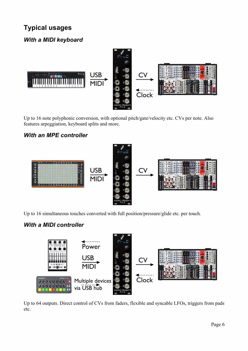
With a MIDI keyboard
Up to 16 note polyphonic conversion, with optional pitch/gate/velocity etc. CVs per note. Also features arpeggiation, keyboard splits and more.
With an MPE controller
Up to 16 simultaneous touches converted with full position/pressure/glide etc. per touch.
With a MIDI controller
Up to 64 outputs. Direct control of CVs from faders, flexible and syncable LFOs, triggers from pads etc.
Page 6
CVUSB MIDI
Clock
CVUSB MIDI
CVUSB MIDI
ClockMultiple devices via USB hub
Power
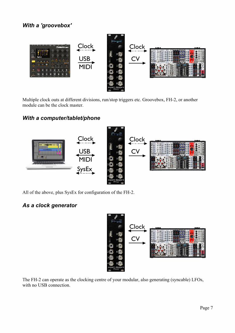
With a 'groovebox'
Multiple clock outs at different divisions, run/stop triggers etc. Groovebox, FH-2, or another module can be the clock master.
With a computer/tablet/phone
All of the above, plus SysEx for configuration of the FH-2.
As a clock generator
The FH-2 can operate as the clocking centre of your modular, also generating (syncable) LFOs, with no USB connection.
Page 7
CVUSB MIDI
Clock Clock
CVUSB MIDI
Clock Clock
SysEx
CV
Clock
InstallationHouse the module in a Eurorack case of your choosing. The power connector is Doepfer standard1. If using the power cable supplied with the module, the red edge of the cable is furthest from the top edge of the PCB, and carries -12V. ("-12V" is marked on the PCB itself next to this end of the connector.) Be sure to connect the other end of the power cable correctly, again so -12V corresponds to the red stripe on the cable.
Power requirements
The FH-2 draws 118mA on the +12V rail, and 48mA on the -12V rail.
It does not use the 5V rail, except for powering USB devices if so configured, as described below.
Understanding USB 'hosts' and 'devices'
In USB there is a clear distinction between 'hosts' and 'devices'. A 'device' has to connect to a 'host'. A 'host' can connect to one or more 'devices' (using a hub for multiple connections). A 'host' may power a 'device', or a 'device' may be self-powered.
In normal computing terms, the host is usually the PC, laptop, tablet etc. Devices are things like mice, keyboards, drives etc. and most USB MIDI hardware also falls into this category.
The FH-2 can operate both as a host and as a device (and can do both at the same time). The USB A socket (the upper, larger one) operates as a host – this is where you connect USB devices (including hubs). The USB C socket (the lower, smaller one) operates as a device – using this you can connect the FH-2 directly to a USB host such as a computer.
There is (currently) no difference in behaviour depending on whether the FH-2 receives its MIDI from the host or device port – both are handled in exactly the same way.
Connecting and powering USB devices
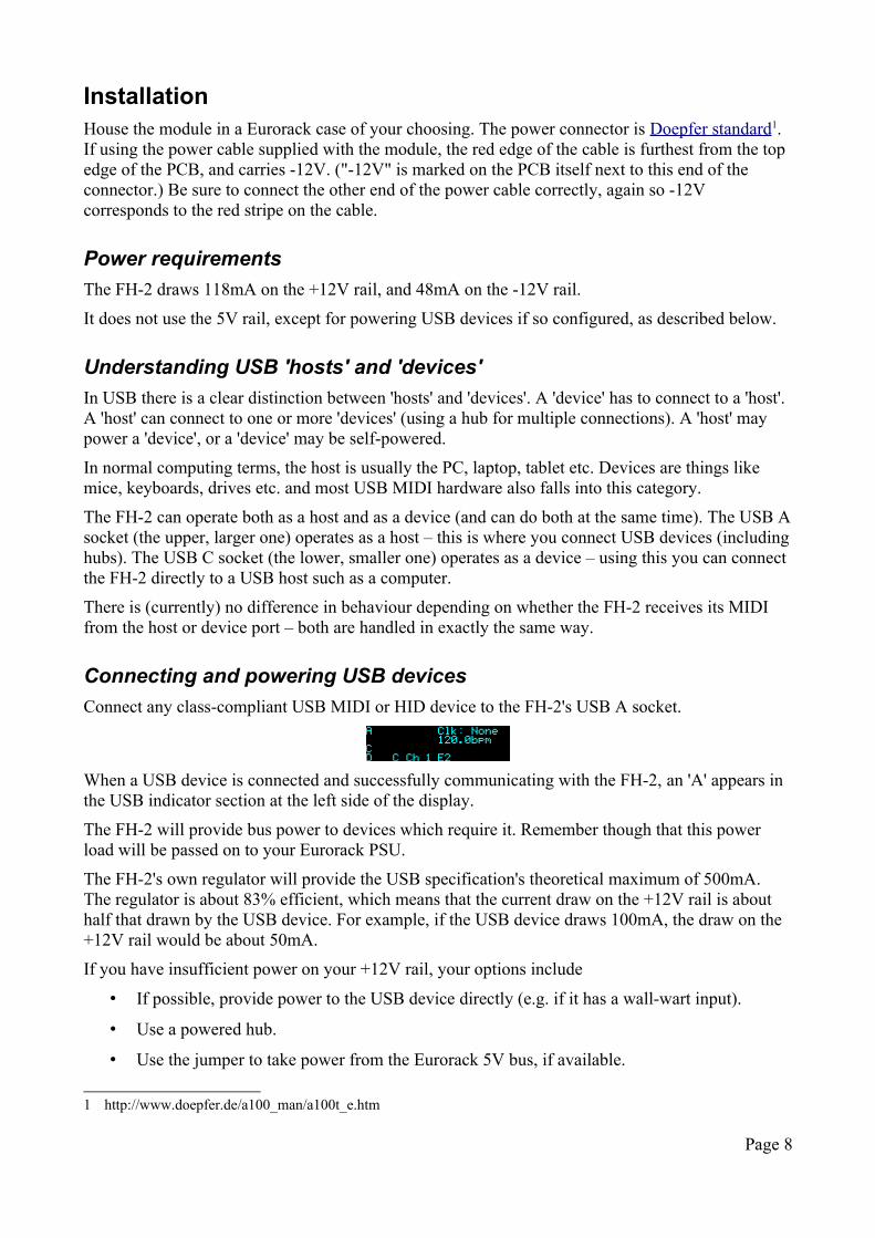
Connect any class-compliant USB MIDI or HID device to the FH-2's USB A socket.
When a USB device is connected and successfully communicating with the FH-2, an 'A' appears in the USB indicator section at the left side of the display.
The FH-2 will provide bus power to devices which require it. Remember though that this power load will be passed on to your Eurorack PSU.
The FH-2's own regulator will provide the USB specification's theoretical maximum of 500mA. The regulator is about 83% efficient, which means that the current draw on the +12V rail is about half that drawn by the USB device. For example, if the USB device draws 100mA, the draw on the +12V rail would be about 50mA.
If you have insufficient power on your +12V rail, your options include
• If possible, provide power to the USB device directly (e.g. if it has a wall-wart input).
• Use a powered hub.
• Use the jumper to take power from the Eurorack 5V bus, if available.
1 http://www.doepfer.de/a100_man/a100t_e.htm
Page 8
The jumper is labelled 'JP1' and is located close to the module's power connector. It has three pins, and its function is as follows:
• Jumper across pins 1 & 2: take USB power from the FH-2's own regulator
• Jumper across pins 2 & 3: take USB power from the Euroack 5V bus.
Needless to say, to make use of the second option your Eurorack PSU needs to be one that supplies 5V in addition to the usual ±12V.
USB hubs
A USB hub can be connected to the FH-2's USB A socket, and then multiple USB MIDI devices connected to the hub. The FH-2 supports up to four devices at once.
Connecting to a USB host
Connect any class-compliant USB MIDI host to the FH-2's USB C socket. Note that this does not require the host to have a USB C socket, or to support USB 3.0. For hosts without a USB C socket, use a 'Type A to type C' cable, specified for USB 2.0 or USB 3.0.
The FH-2 does not draw power from the USB C socket.
When a USB host is connected and successfully communicating with the FH-2, a 'C' appears in the USB indicator section at the left side of the display.
Connecting expansion modules
The 10 pin header labelled GT2 provides expansion in conjunction with the FHX-1 Output Expander2 and the FHX-8GT Gate Expander3. Connect the 10-way cable provided with the FHX-1 or FHX-8GT to this header, oriented the same way as it is on the expander.
An FH-1 module may also be used as an expander, connected via a USB A to USB C cable to the FH-2's USB C socket. The FH-1 should be configured in its default state. On the FH-2, enable the FH-1 as an expander in the Settings. The FH-1 takes the place of the first FHX-1 ('Show FHX-1 Expander Output Configurator 1' in the config tool).
An FHX-1 output can be used for any purpose, just like the FH-2's own outputs. The FHX-8GT outputs can only be used for 'gate' type purposes e.g. gates, triggers, clocks, & Euclidean patterns.
Output numbering
Taking the expanders into account, there are a total of 128 possible outputs available – 64 CV outputs from the FH-1 and FHX-1s, and 64 gate outputs from the FHX-8GTs.
In the FH-2 UI, a single output number is often used, in which case outputs 1-8 are the FH-2's own outputs, outputs 9-64 are the FHX-1 outputs, and outputs 65-128 are the FHX-8GT outputs.
In the web UI, the FHX-1 outputs are numbered '1/1' to '7/8' (outputs 1-8 on each of 7 possible FHX-1s), and the FHX-8GT outputs are numbered from '0/1' to '3/16' (outputs 1-16 on each of 4 possible FHX-8GTs).
2 http://www.expert-sleepers.co.uk/fhx1.html3 http://www.expert-sleepers.co.uk/fhx8gt.html
Page 9
Inputs and OutputsThe FH-2 has eight outputs, numbered 1-8, and two inputs, named X & Y.
The outputs are all equivalent, and any output can be assigned any function.
The digital-to-analogue conversion is at 14 bit resolution.
The voltage range of an output is adjustable, as set in the configuration (see below).
The function of the inputs is also set in the configuration. In some cases the inputs are digital inputs, responding to simple on/off signals, and in some cases the inputs are analogue, in which case the analogue-to-digital conversion is 12 bit. In both cases, the preferred input voltage range is 0-5V, but voltages outside of this range will not damage the module.
ControlsThe FH-2 has two controls
– a rotary encoder, which is also a push button, to the lower right of the display
– a push button, to the lower left of the display.
From here on these will be referred to as 'the encoder' and 'the left button'.
Display ModesThe FH-2's display is usually in one of a small number of modes.
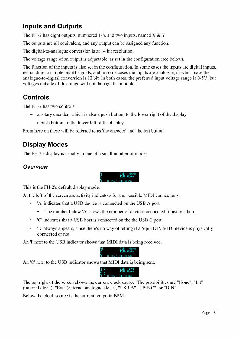
Overview
This is the FH-2's default display mode.
At the left of the screen are activity indicators for the possible MIDI connections:
• 'A' indicates that a USB device is connected on the USB A port.
• The number below 'A' shows the number of devices connected, if using a hub.
• 'C' indicates that a USB host is connected on the the USB C port.
• 'D' always appears, since there's no way of telling if a 5-pin DIN MIDI device is physically connected or not.
An 'I' next to the USB indicator shows that MIDI data is being received.
An 'O' next to the USB indicator shows that MIDI data is being sent.
The top right of the screen shows the current clock source. The possibilities are "None", "Int" (internal clock), "Ext" (external analogue clock), "USB A", "USB C", or "DIN".
Below the clock source is the current tempo in BPM.
Page 10
At the bottom of the screen the FH-2 shows the most recently received MIDI message, formatted as
source (A/C/D) / channel / message type (e.g. CC) / byte 1 (e.g. CC number) / byte 2 (e.g. value)
In this display mode, pressing the encoder enters the menu system.
Turning the encoder and pressing the left button can have various functions, configured in the Settings.
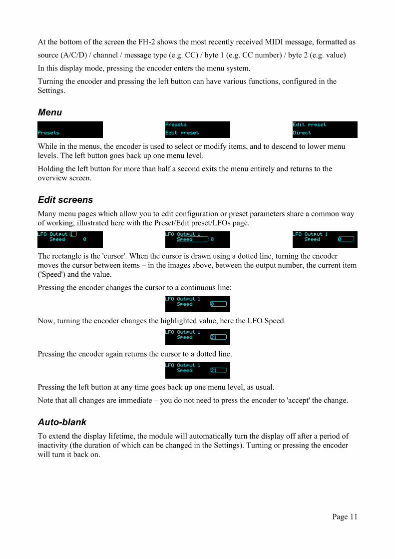
Menu
While in the menus, the encoder is used to select or modify items, and to descend to lower menu levels. The left button goes back up one menu level.
Holding the left button for more than half a second exits the menu entirely and returns to the overview screen.
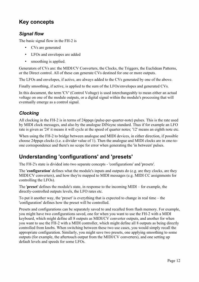
Edit screens
Many menu pages which allow you to edit configuration or preset parameters share a common way of working, illustrated here with the Preset/Edit preset/LFOs page.
The rectangle is the 'cursor'. When the cursor is drawn using a dotted line, turning the encoder moves the cursor between items – in the images above, between the output number, the current item ('Speed') and the value.
Pressing the encoder changes the cursor to a continuous line:
Now, turning the encoder changes the highlighted value, here the LFO Speed.
Pressing the encoder again returns the cursor to a dotted line.
Pressing the left button at any time goes back up one menu level, as usual.
Note that all changes are immediate – you do not need to press the encoder to 'accept' the change.
Auto-blank
To extend the display lifetime, the module will automatically turn the display off after a period of inactivity (the duration of which can be changed in the Settings). Turning or pressing the encoder will turn it back on.
Page 11
Key concepts
Signal flow
The basic signal flow in the FH-2 is
• CVs are generated
• LFOs and envelopes are added
• smoothing is applied.
Generators of CVs are: the MIDI/CV Converters, the Clocks, the Triggers, the Euclidean Patterns, or the Direct control. All of these can generate CVs destined for one or more outputs.
The LFOs and envelopes, if active, are always added to the CVs generated by one of the above.
Finally smoothing, if active, is applied to the sum of the LFOs/envelopes and generated CVs.
In this document, the term 'CV' (Control Voltage) is used interchangeably to mean either an actual voltage on one of the module outputs, or a digital signal within the module's processing that will eventually emerge as a control signal.
Clocking
All clocking in the FH-2 is in terms of 24ppqn (pulse-per-quarter-note) pulses. This is the rate used by MIDI clock messages, and also by the analogue DINsync standard. Thus if for example an LFO rate is given as '24' it means it will cycle at the speed of quarter notes; '12' means an eighth note etc.
When using the FH-2 to bridge between analogue and MIDI devices, in either direction, if possible choose 24ppqn clocks (i.e. a divider value of 1). Then the analogue and MIDI clocks are in one-to-one correspondence and there's no scope for error when generating the 'in between' pulses.
Understanding 'configurations' and 'presets'The FH-2's state is divided into two separate concepts - 'configurations' and 'presets'.
The 'configuration' defines what the module's inputs and outputs do (e.g. are they clocks, are they MIDI/CV converters), and how they're mapped to MIDI messages (e.g. MIDI CC assignments for controlling the LFOs).
The 'preset' defines the module's state, in response to the incoming MIDI – for example, the directly-controlled outputs levels, the LFO rates etc.
To put it another way, the 'preset' is everything that is expected to change in real time – the 'configuration' defines how the preset will be controlled.
Presets and configurations can be separately saved to and recalled from flash memory. For example, you might have two configurations saved, one for when you want to use the FH-2 with a MIDI keyboard, which might define all 8 outputs as MIDI/CV converter outputs, and another for when you want to use the FH-2 with a MIDI controller, which might define all 8 outputs as being directly controlled from knobs. When switching between these two use cases, you would simply recall the appropriate configuration. Similarly, you might save two presets, one applying smoothing to some outputs (for example, the aftertouch output from the MIDI/CV converters), and one setting up default levels and speeds for some LFOs.
Page 12
Configurations menuConfigurations can be stored to flash memory. There are 30 configuration slots in flash.
In what follows, the 'current configuration' means the current module state, in RAM, not any of the flash configuration locations.
The Configurations menu is accessed at the top menu level; the submenu items are as follows.
Edit configuration
Allows you to edit the current configuration directly. See below for details of what makes up a configuration.
Note that you may find it more convenient to edit the configuration using the browser-based tool – see below.
Load configuration
The 'Load configuration' menu allows you to select one of the configuration slots, displaying its number and the name of the configuration stored in that slot. Pressing the encoder shows the message 'Are you sure?' - press the encoder again to load the configuration.
Save configuration
The 'Save configuration' menu allows you to select one of the configuration slots, displaying its number and the name of the configuration stored in that slot. Pressing the encoder shows the message 'Are you sure?' - press the encoder again to save the current configuration into the selected slot.
Reset configuration
This menu allows you to reset the current configuration to default values. It has no effect on the presets in flash memory.
Name configuration
This allows you to edit the name of the current configuration. Typically you would do this before saving it to flash.
A dotted rectangle indicates the current cursor position. Turning the encoder moves the cursor. Pressing the encoder turns the rectangle into an underscore; turning the encoder now changes the character above the cursor.
Pressing the encoder again returns to the dotted cursor.
Page 13
Presets menuPresets can be stored to flash memory. There are 30 preset slots in flash.
In what follows, the 'current preset' means the current module state, in RAM, not any of the flash preset locations.
The Presets menu is accessed at the top menu level; the submenu items are as follows.
Edit preset
Allows you to edit the current preset directly (rather than in response to MIDI). See below for details of what makes up a preset.
Load preset
The 'Load preset' menu allows you to select one of the preset slots, displaying its number and the name of the preset stored in that slot. Pressing the encoder shows the message 'Are you sure?' - press the encoder again to load the preset.
Save preset
The 'Save preset' menu allows you to select one of the preset slots, displaying its number and the name of the preset stored in that slot. Pressing the encoder shows the message 'Are you sure?' - press the encoder again to save the current preset into the selected slot.
Reset preset
This menu allows you to reset the current preset to default values. It has no effect on the presets in flash memory.
Name Preset
This allows you to edit the name of the current preset. Typically you would do this before saving it to flash.
Editing the preset name works in the same way as editing the configuration name, above.
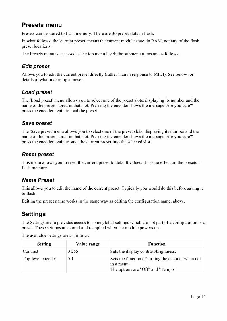
SettingsThe Settings menu provides access to some global settings which are not part of a configuration or a preset. These settings are stored and reapplied when the module powers up.
The available settings are as follows.
Setting Value range Function
Contrast 0-255 Sets the display contrast/brightness.
Top-level encoder 0-1 Sets the function of turning the encoder when not in a menu.The options are "Off" and "Tempo".
Page 14
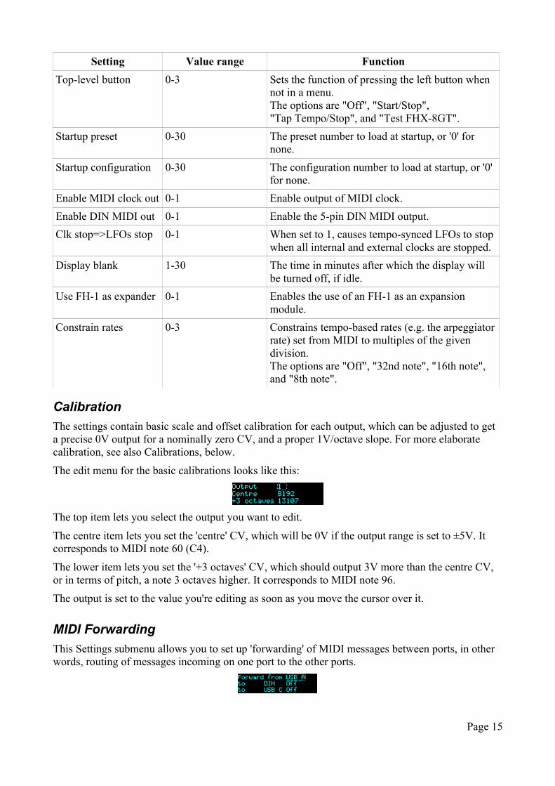
Setting Value range Function
Top-level button 0-3 Sets the function of pressing the left button when not in a menu.The options are "Off", "Start/Stop", "Tap Tempo/Stop", and "Test FHX-8GT".
Startup preset 0-30 The preset number to load at startup, or '0' for none.
Startup configuration 0-30 The configuration number to load at startup, or '0' for none.
Enable MIDI clock out 0-1 Enable output of MIDI clock.
Enable DIN MIDI out 0-1 Enable the 5-pin DIN MIDI output.
Clk stop=>LFOs stop 0-1 When set to 1, causes tempo-synced LFOs to stop when all internal and external clocks are stopped.
Display blank 1-30 The time in minutes after which the display will be turned off, if idle.
Use FH-1 as expander 0-1 Enables the use of an FH-1 as an expansion module.
Constrain rates 0-3 Constrains tempo-based rates (e.g. the arpeggiator rate) set from MIDI to multiples of the given division.The options are "Off", "32nd note", "16th note", and "8th note".
Calibration
The settings contain basic scale and offset calibration for each output, which can be adjusted to get a precise 0V output for a nominally zero CV, and a proper 1V/octave slope. For more elaborate calibration, see also Calibrations, below.
The edit menu for the basic calibrations looks like this:
The top item lets you select the output you want to edit.
The centre item lets you set the 'centre' CV, which will be 0V if the output range is set to ±5V. It corresponds to MIDI note 60 (C4).
The lower item lets you set the '+3 octaves' CV, which should output 3V more than the centre CV, or in terms of pitch, a note 3 octaves higher. It corresponds to MIDI note 96.
The output is set to the value you're editing as soon as you move the cursor over it.
MIDI Forwarding
This Settings submenu allows you to set up 'forwarding' of MIDI messages between ports, in other words, routing of messages incoming on one port to the other ports.
Page 15
On the top line, select the MIDI source (USB A, USB C or DIN). On the two lines below you can then enable or disable routing of MIDI messages from the source to the other two ports.
Reset Settings
This menu allows you to reset the settings to default values.
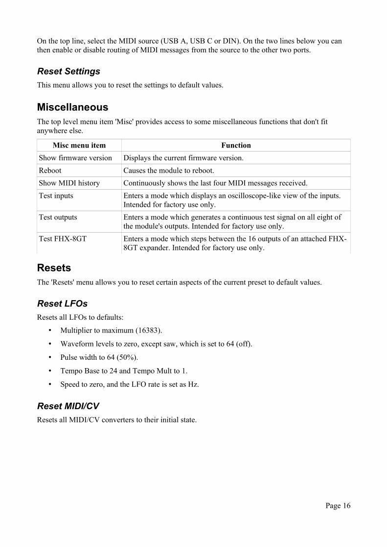
MiscellaneousThe top level menu item 'Misc' provides access to some miscellaneous functions that don't fit anywhere else.
Misc menu item Function
Show firmware version Displays the current firmware version.
Reboot Causes the module to reboot.
Show MIDI history Continuously shows the last four MIDI messages received.
Test inputs Enters a mode which displays an oscilloscope-like view of the inputs. Intended for factory use only.
Test outputs Enters a mode which generates a continuous test signal on all eight of the module's outputs. Intended for factory use only.
Test FHX-8GT Enters a mode which steps between the 16 outputs of an attached FHX-8GT expander. Intended for factory use only.
ResetsThe 'Resets' menu allows you to reset certain aspects of the current preset to default values.
Reset LFOs
Resets all LFOs to defaults:
• Multiplier to maximum (16383).
• Waveform levels to zero, except saw, which is set to 64 (off).
• Pulse width to 64 (50%).
• Tempo Base to 24 and Tempo Mult to 1.
• Speed to zero, and the LFO rate is set as Hz.
Reset MIDI/CV
Resets all MIDI/CV converters to their initial state.
Page 16
ConfigurationsA configuration consists of the following:
• the configuration name
• some global settings (trigger length, global transpose etc.)
• setup of the MIDI/CV converters
• setup of the MIDI CC assignments ('mappings')
• setup of the HID gamepad and keyboard assignments
• setup of the Clocks
• setup of the Triggers
• setup of the Euclidean Patterns
• for every output:
• the voltage range setting
• the output levels used if the output is a gate/trigger
Configurations can be edited directly via the menu system, or via SysEx. A browser-based tool is provided to edit configurations via SysEx, here4.
Name
The configuration name is 16 characters long.
Globals
These are items that don't refer to a specific output or function.
Name Value range
Description
Trigger length 1-100 Length of all triggers, in milliseconds.
Global transpose -48 - 48 Applies a transposition to all MIDI/CV converters.
Legato velocity 0-1 When enabled, playing legato in monophonic MIDI/CV modes will use the note velocity only from the first note in a phrase.
Ext Clock Multiplier 1-96 Sets the multiplier relating the (incoming) external clock to the internal 24ppqn timebase.
Ext Clock Run Control 0-1 Sets the run control option (see below).
Euclidean Accent 0-127 Sets the scaling of non-accented pulses when accents are enable for Euclidean Patterns (see below).
Example values for 'Ext Clock Multiplier' would be '24' for quarter note clocks, and '1' for 24ppqn clocks e.g. a DINsync clock.
4 http://expert-sleepers.co.uk/webapps/fh2_config_tool.html
Page 17
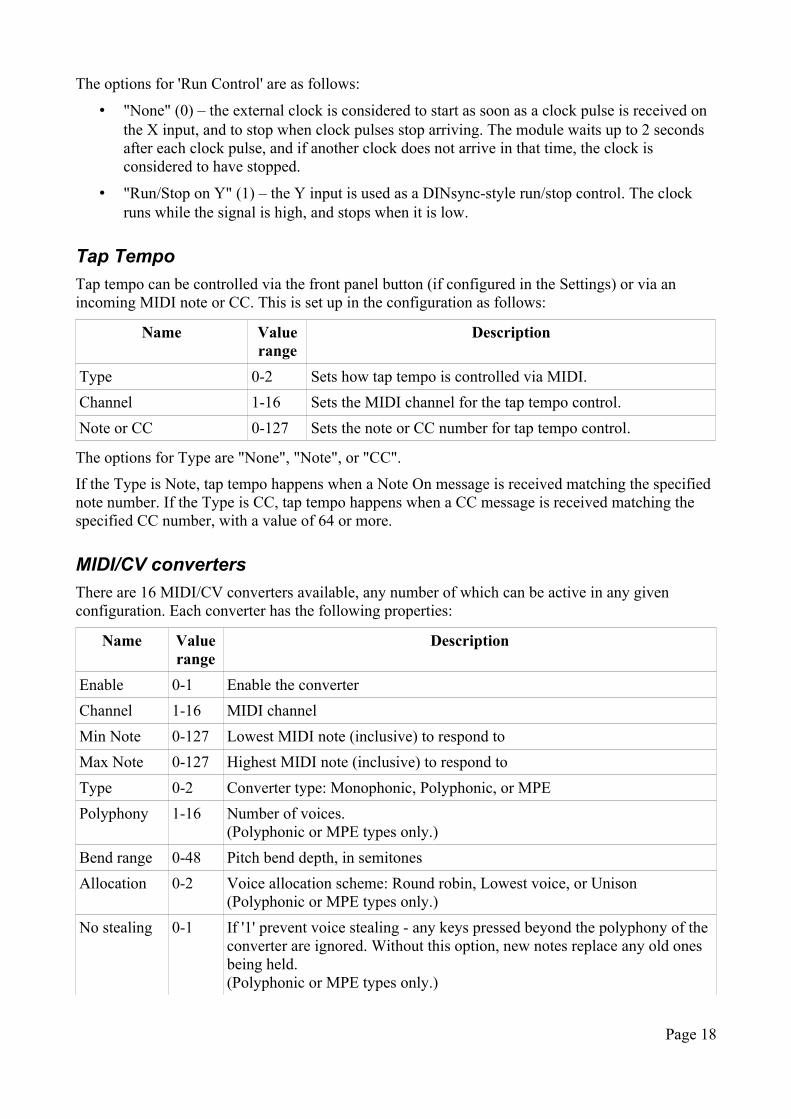
The options for 'Run Control' are as follows:
• "None" (0) – the external clock is considered to start as soon as a clock pulse is received on the X input, and to stop when clock pulses stop arriving. The module waits up to 2 seconds after each clock pulse, and if another clock does not arrive in that time, the clock is considered to have stopped.
• "Run/Stop on Y" (1) – the Y input is used as a DINsync-style run/stop control. The clock runs while the signal is high, and stops when it is low.
Tap Tempo
Tap tempo can be controlled via the front panel button (if configured in the Settings) or via an incoming MIDI note or CC. This is set up in the configuration as follows:
Name Value range
Description
Type 0-2 Sets how tap tempo is controlled via MIDI.
Channel 1-16 Sets the MIDI channel for the tap tempo control.
Note or CC 0-127 Sets the note or CC number for tap tempo control.
The options for Type are "None", "Note", or "CC".
If the Type is Note, tap tempo happens when a Note On message is received matching the specified note number. If the Type is CC, tap tempo happens when a CC message is received matching the specified CC number, with a value of 64 or more.
MIDI/CV converters
There are 16 MIDI/CV converters available, any number of which can be active in any given configuration. Each converter has the following properties:
Name Value range
Description
Enable 0-1 Enable the converter
Channel 1-16 MIDI channel
Min Note 0-127 Lowest MIDI note (inclusive) to respond to
Max Note 0-127 Highest MIDI note (inclusive) to respond to
Type 0-2 Converter type: Monophonic, Polyphonic, or MPE
Polyphony 1-16 Number of voices.(Polyphonic or MPE types only.)
Bend range 0-48 Pitch bend depth, in semitones
Allocation 0-2 Voice allocation scheme: Round robin, Lowest voice, or Unison(Polyphonic or MPE types only.)
No stealing 0-1 If '1' prevent voice stealing - any keys pressed beyond the polyphony of the converter are ignored. Without this option, new notes replace any old ones being held.(Polyphonic or MPE types only.)
Page 18
Name Value range
Description
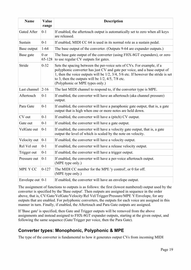
Gated After 0-1 If enabled, the aftertouch output is automatically set to zero when all keys are released.
Sustain 0-1 If enabled, MIDI CC 64 is used in its normal role as a sustain pedal.
Base output 1-64 The base output of the converter. (Outputs 9-64 are expander outputs.)
Base gate 0 or 65-128
The base gate output of the converter (using FHX-8GT expanders), or zero to use regular CV outputs for gates.
Stride 0-32 Sets the spacing between the per-voice sets of CVs. For example, if a polyphonic converter has just CV and gate per voice, and a base output of 1, then the voice outputs will be 1/2, 3/4, 5/6 etc. If however the stride is set to 3, then the outputs will be 1/2, 4/5, 7/8 etc.(Polyphonic or MPE types only.)
Last channel 2-16 The last MIDI channel to respond to, if the converter type is MPE.
Aftertouch 0-1 If enabled, the converter will have an aftertouch (aka channel pressure) output.
Para Gate 0-1 If enabled, the converter will have a paraphonic gate output, that is, a gate output that is high when one or more notes are held down.
CV out 0-1 If enabled, the converter will have a (pitch) CV output.
Gate out 0-1 If enabled, the converter will have a gate output.
VelGate out 0-1 If enabled, the converter will have a velocity gate output, that is, a gate output the level of which is scaled by the note on velocity.
Velocity out 0-1 If enabled, the converter will have a velocity output.
Rel Vel out 0-1 If enabled, the converter will have a release velocity output.
Trigger out 0-1 If enabled, the converter will have a trigger output.
Pressure out 0-1 If enabled, the converter will have a per-voice aftertouch output.(MPE type only.)
MPE Y CC 0-127 The MIDI CC number for the MPE 'y control', or 0 for off.(MPE type only.)
Envelope out 0-1 If enabled, the converter will have an envelope output.
The assignment of functions to outputs is as follows: the first (lowest numbered) output used by the converter is specified by the 'Base output'. Then outputs are assigned in sequence in the order above, that is, CV/Gate/VelGate/Velocity/Rel Vel/Trigger/Pressure/MPE Y/Envelope, for any outputs that are enabled. For polyphonic converters, the outputs for each voice are assigned in this manner in turn. Finally, if enabled, the Aftertouch and Para Gate outputs are assigned.
If 'Base gate' is specified, then Gate and Trigger outputs will be removed from the above assignments and instead assigned to FHX-8GT expander outputs, starting at the given output, and following the same sequence (Gate/Trigger per voice, then the Para Gate).
Converter types: Monophonic, Polyphonic & MPE
The type of the converter is fundamental to how it generates output CVs from incoming MIDI
Page 19
notes.
– Monophonic converters generate a single voice's set of CVs – one pitch, gate etc. A monophonic converter receives on one MIDI channel only. Incoming MIDI notes replace the current note.
– Polyphonic converters generate CVs for a number of voices, controlled by the converter's polyphony setting. Each voice has the same set of CVs; there are also two CVs that apply globally (the paraphonic gate and aftertouch CVs). A polyphonic converter receives on one MIDI channel only. Incoming MIDI notes are assigned to the voices according to the Voice Allocation and Prevent Stealing settings.
– MPE converters are much like polyphonic converters, but also make use of MIDI Polyphonic Expression or MPE5. An MPE converter receives on a number of MIDI channels. The Channel setting is taken as the MPE 'global' channel, so the voice channels will begin one channel up from that. The last channel to receive on is set by the Last Channel setting. So for example if Channel is 2 and Last Channel is 14, the converter will receive MIDI notes on channels 3 to 14.MPE converters may have per-channel aftertouch and 'Y dimension' CVs. The y dimension CV is enabled by choosing its CC number; 0 means off. Typically MPE controllers default to CC #74 for the y dimension.
Mappings
The mappings section defines how the FH-2 will respond to MIDI controllers, typically MIDI CCs (continuous controllers).
A configuration can have a maximum of 256 mappings. Each mapping has
– a source MIDI channel
– a source MIDI message type (currently only CC is implemented)
– a target.
The target of a mapping can be one of
– a per-output preset item: the direct level, or one of the LFO parameters.
– a per-MIDI/CV converter item: the arpeggiator parameters, or portamento.
– a per-Euclidean pattern item.
Many items that can be controlled by mappings have a range of 0-127 anyway, so the MIDI CC value is simply used directly. In other cases the MIDI CC range of 0-127 is scaled to map onto the range of the controlled parameter.
14 bit MIDI CCs
Some of the FH-2 parameters use a 14 bit representation for higher accuracy: specifically, the Direct levels, the LFO Speed and the LFO Multiplier.
A convention exists for sending 14 bit values via MIDI CCs, using two CCs (of 7 bits each).6 The high 7 bits are sent on a CC in the range 0-31, and the low 7 bits are sent on the CC numbered 32
5 https://www.midi.org/articles/midi-polyphonic-expression-mpehttps://www.midi.org/specifications/item/the-midi-1-0-specification (at bottom of page)
6 Hardware controllers supporting this convention include the Faderfox UC3.
Page 20
higher (which is therefore in the range 32-63). The low 7 bits are sent first.
The FH-2 configures this automatically, if
– one of the three 14 bit quantities is mapped to CC in the range 0-31, and
– the corresponding low bits CC is not mapped to anything else.
For example, say the direct level on output 5 is mapped to CC 4 on MIDI channel 1 (as it is in the default configuration). Then CC 36 (36 being 4 + 32) on MIDI channel 1 is automatically mapped as the low 7 bits, unless that CC has been explicitly mapped to control something else.
Note that this doesn't mean you have to control these quantities with 14 bit controllers. Sending a single CC to control the mapped value will control it perfectly well, just at a coarser resolution.
Voltage range
Each output of the FH-2 can be switched between voltage ranges of 0-10V, ±5V, and 0-1V7.
The FHX-1 expander outputs can be switched between 0-10V and ±5V, but for the FHX-1 this is done via a physical jumper on the module, rather than being software-configurable.
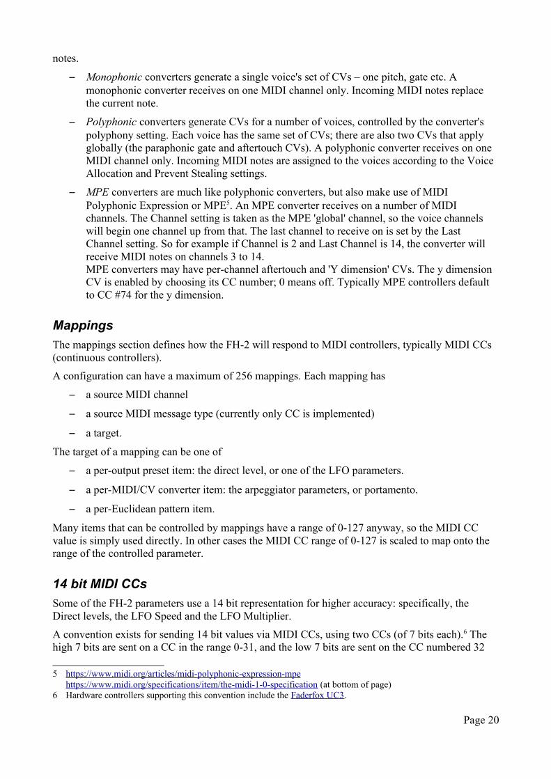
Clocks
There are 32 clock generators available. These parameters define the clock:
Name Value range Description
Clock Type 0-6 The type of clock output: one of None, Clock, Run/Stop, Stop/Run, Start Trig, Stop Trig, or Both Trig
Clock Base 1-96 The rate of the clock, in terms of 24ppqn pulses. Some convenient values include:24 quarter notes12 eighth notes8 eighth note triplets6 sixteenth notes
Multiplier 1-127 Multiplies the 'clock base' to give the actual clock rate. So for example if 'clock base' is 12 (1/8th notes) and 'multiplier' is 3, the clock will run at a rate of 3/8th notes.
Length 0-127 The length of the clock pulse in milliseconds. The special value '0' means that the clock is not a pulse, but a 50% duty cycle square wave.
Output 1-128 The clock output. (Outputs 9-128 are expander outputs.)
Shift 0-127 The amount by which to advance the clock, in terms of 24ppqn pulses. For example a half note clock advanced by a quarter note will fall on the off beats (2 & 4 of a 4/4 pattern).
7 The 0-1V setting is provided primarily for compatibility with certain video synthesis modules.
Page 21
Triggers
There are 32 trigger generators available, which take an incoming MIDI note and generate a trigger or gate signal in response. These parameters define the trigger generator:
Name Value range Description
Trig Type 0-6 The type of trigger output: one of None, Trigger, Gate, Vel Trig, Vel Gate, Acc Trig, Acc Gate
Channel 1-16 The MIDI channel.
Note 1-127 The MIDI note number.
Output 1-128 The trigger output. (Outputs 9-128 are expander outputs.)
The type of the trigger can be 'Trigger', a pulse (set by the configuration's global trigger length), or 'Gate', which stays high as long as the MIDI note is held.
'Vel Trig' and 'Vel Gate' use the MIDI note's velocity to set the output trigger level.
'Acc Trig' and 'Acc Gate' generate both the base trigger/gate and an additional accent trigger/gate, on the next output up (e.g. if the trigger output is set to 7, the accent will be on 8). The accent fires when the MIDI note velocity is 96 or more.
Euclidean Patterns
Most of the Euclidean Pattern setup is in the preset – see below. The configuration only defines the outputs that each pattern generator uses. The 'Output' outputs a trigger whenever a 'pulse' occurs in the pattern; the 'Off Output' outputs a trigger on steps where a 'pulse' does not occur.
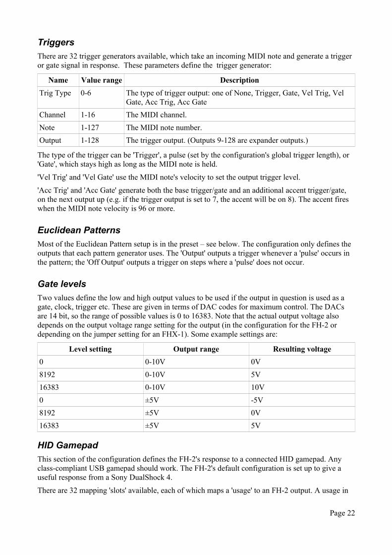
Gate levels
Two values define the low and high output values to be used if the output in question is used as a gate, clock, trigger etc. These are given in terms of DAC codes for maximum control. The DACs are 14 bit, so the range of possible values is 0 to 16383. Note that the actual output voltage also depends on the output voltage range setting for the output (in the configuration for the FH-2 or depending on the jumper setting for an FHX-1). Some example settings are:
Level setting Output range Resulting voltage
0 0-10V 0V
8192 0-10V 5V
16383 0-10V 10V
0 ±5V -5V
8192 ±5V 0V
16383 ±5V 5V
HID Gamepad
This section of the configuration defines the FH-2's response to a connected HID gamepad. Any class-compliant USB gamepad should work. The FH-2's default configuration is set up to give a useful response from a Sony DualShock 4.
There are 32 mapping 'slots' available, each of which maps a 'usage' to an FH-2 output. A usage in
Page 22
USB HID terminology is a button press or joystick axis etc.
If a gamepad button is mapped, the button pressed/released status is simply mapped to the selected output, using the gate levels set in the configuration (see above).
If a continuous quantity from the gamepad is mapped (e.g. a joystick axis), you can set a scale and offset that translates the USB HID value to the output DAC value. The values set in the configuration are multiplied by 4 to give the final 14 bit DAC code. For example, in the default configuration, axis Y is mapped with scale -16 and offset 4096. The USB HID value is 8 bit i.e. has the range 0-255, so these values cover the full DAC range:
4*(4096-16*0)=16384 4*(4096-16*255)=64
HID Keyboard
This section of the configuration defines the FH-2's response to a connected HID keyboard (i.e. a generic USB computer keyboard, not a musical keyboard). The FH-2's default configuration maps the keyboard keys 1-8 to the FH-2's eight outputs.
There are 32 mapping 'slots' available, each of which maps a key to an FH-2 output.
There are two types of mapping available: 'Press/Release' and 'Press only'. 'Press/Release' mappings change the output on key press and key release, and as such might be useful as triggers, gates etc. 'Press only' mappings only change the output on key press; this could be used to choose from a number of different CV values for an output, depending on which key was last pressed.
The output values for each key press and release can be set in the configuration. These are DAC codes – see the description of the gate levels, above.
Using the Configuration Tool
A browser-based tool is provided to edit configurations via SysEx, the most recent version of which is always here8 (older versions are available to match each firmware release). This uses the Web MIDI API, which at the time of writing will work only in Google's Chrome browser.
All is well if the tool shows Web MIDI status: OK
If it shows Web MIDI status: No MIDI support in your browser then you need to use a different browser.
The tool needs a MIDI connection to the FH-2. It is most convenient to connect the FH-2 directly to the computer running the tool via its USB C port, but it will work just as well connected indirectly via its USB A port or 5-pin DIN connection.
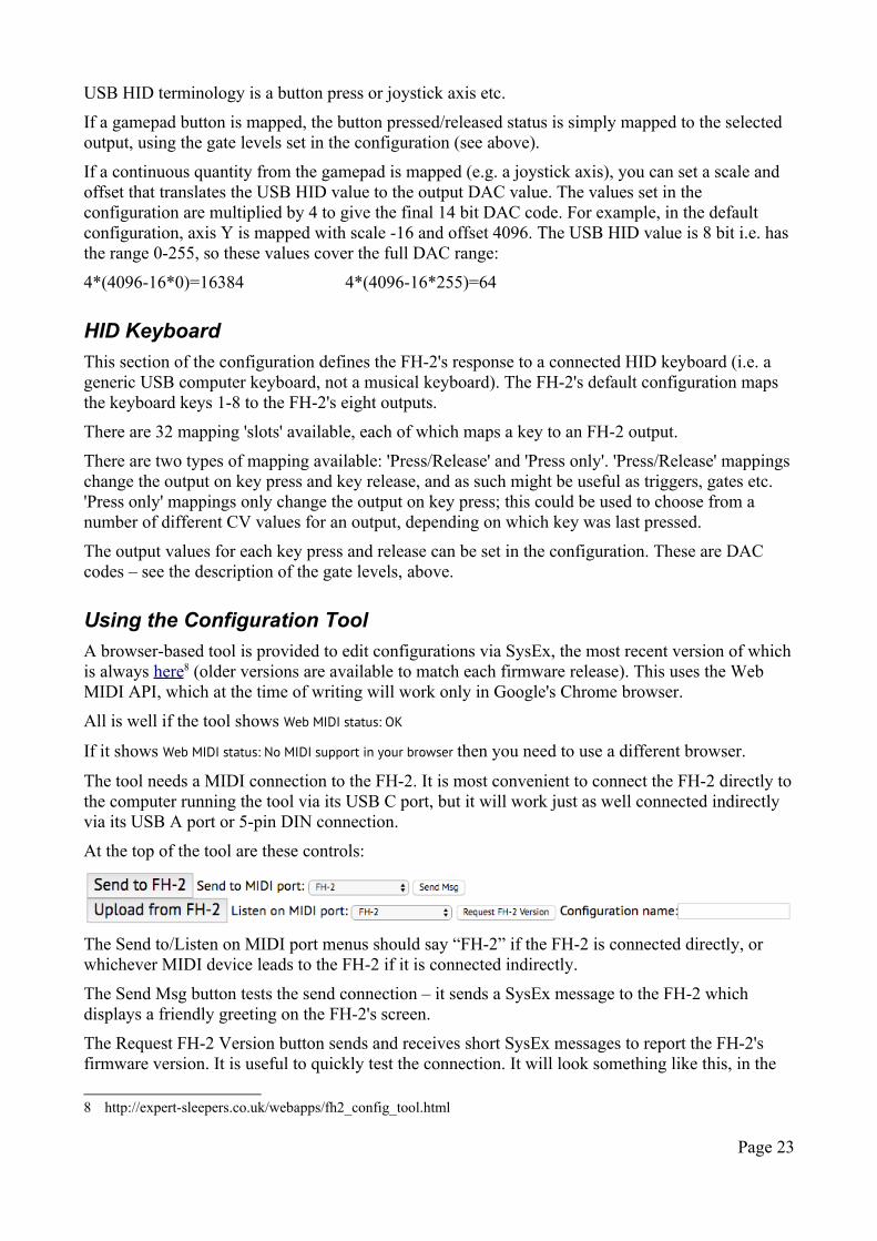
At the top of the tool are these controls:
The Send to/Listen on MIDI port menus should say “FH-2” if the FH-2 is connected directly, or whichever MIDI device leads to the FH-2 if it is connected indirectly.
The Send Msg button tests the send connection – it sends a SysEx message to the FH-2 which displays a friendly greeting on the FH-2's screen.
The Request FH-2 Version button sends and receives short SysEx messages to report the FH-2's firmware version. It is useful to quickly test the connection. It will look something like this, in the
8 http://expert-sleepers.co.uk/webapps/fh2_config_tool.html
Page 23
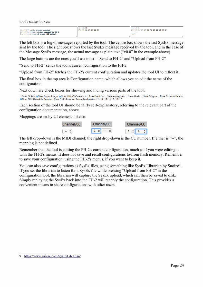
tool's status boxes:
The left box is a log of messages reported by the tool. The centre box shows the last SysEx message sent by the tool. The right box shows the last SysEx message received by the tool, and in the case of the Message SysEx message, the actual message as plain text (“v0.0” in the example above).
The large buttons are the ones you'll use most - “Send to FH-2” and “Upload from FH-2”.
“Send to FH-2” sends the tool's current configuration to the FH-2.
“Upload from FH-2” fetches the FH-2's current configuration and updates the tool UI to reflect it.
The final box in the top area is Configuration name, which allows you to edit the name of the configuration.
Next down are check boxes for showing and hiding various parts of the tool:
Each section of the tool UI should be fairly self-explanatory, referring to the relevant part of the configuration documentation, above.
Mappings are set by UI elements like so:
The left drop-down is the MIDI channel; the right drop-down is the CC number. If either is “--”, the mapping is not defined.
Remember that the tool is editing the FH-2's current configuration, much as if you were editing it with the FH-2's menus. It does not save and recall configurations to/from flash memory. Remember to save your configuration, using the FH-2's menus, if you want to keep it.
You can also save configurations as SysEx files, using something like SysEx Librarian by Snoize9. If you set the librarian to listen for a SysEx file while pressing “Upload from FH-2” in the configuration tool, the librarian will capture the SysEx upload, which can then be saved to disk. Simply replaying the SysEx back into the FH-2 will reapply the configuration. This provides a convenient means to share configurations with other users.
9 https://www.snoize.com/SysExLibrarian/
Page 24
PresetsA preset consists of the following:
• the preset name
• the internal clock tempo
• for every output:
• the direct output levels
• the LFO state
• the smoothing amount
• for every MIDI/CV converter:
• the arpeggiator state
• the portamento rate
• the transpose setting
• the choice of Scala scale and keyboard mapping
• the Euclidean pattern generator states
In general most of these can be controlled via MIDI CCs, as defined in the Mappings.
Name
The preset name is 16 characters long.
Internal clock tempo
This is the tempo of the internal clock, set directly or via tap-tempo.
Direct output levels
'Direct' outputs levels is our term for when a MIDI controller directly controls an output e.g. the controller goes from 0-127 and the output goes from 0-10V.
The direct level is a 14 bit quantity – see above. When edited from the menu, a 'coarse' value is shown as well as the actual value. This makes it easier to make large changes.
LFOs
Each output has an LFO, defined by the parameters below. The LFOs are added to any other CV being generated at a particular output. In the absence of a MIDI/CV converter, clock etc. this means the LFO waveforms are centred around the 'direct level' of the output. So, if the voltage range of an output is ±5V, to get an LFO centred on 0V, you would need to set the direct level to 8192 (mid-range) as well as set the LFO amplitudes. Note you needn't map a MIDI controller to set the direct level – you can just edit it via the menus, and if convenient save that as a preset.
The speed of each LFO can be set to a value in Hz, or it can be locked to the current tempo. Which is used depends on the last setting made; setting the 'Speed' switches the LFO into its Hz-based
Page 25
mode, whereas setting the 'Tempo Base' or 'Tempo Mult' switches the LFO into its tempo-synced mode.
Name Description
Speed Sets the LFO speed, from 0.1Hz to 10Hz. A logarithmic scaling of the value is used, to allow finer control over the slower end of the range.A 14 bit quantity.
Tempo Base The rate of the LFO, in terms of 24ppqn pulses.
Tempo Mult Multiplies the 'Tempo Base' to give the actual LFO rate. So for example if 'Tempo Base' is 12 (1/8th notes) and 'multiplier' is 3, the LFO will run at a rate of 3/8th notes.
Multiplier This scales the overall waveform that is the result of combining the 6 basic shapes. It defaults to maximum, so to apply an LFO it is only necessary to set one of the basic shapes to a non-zero level.A 14 bit quantity.
Sine The level of a sine wave's contribution to the LFO shape.
Square The level of a square wave's contribution to the LFO shape.
PW Pulse width control for the square waveform.
Triangle The level of a triangle wave's contribution to the LFO shape.
Saw The level of a saw wave's contribution to the LFO shape.The saw wave is set to zero at value 64. Values greater than 64 give a rising sawtooth shape; values less than 64 give a falling shape.
Random The level of a random signal's contribution to the LFO shape.
Noise The level of a noise signal's contribution to the LFO shape.
Phase The phase of the LFO waveform.
Smoothing
Each output has a 'smoothing' amount. When enabled, a low pass filter is applied to the output to smooth sudden changes into an exponential response. Zero means off; other values apply progressively more smoothing, up to a time constant of about 1 second.
Smoothing applies to every function of the FH-2: direct control, LFOs, sequencers, etc. You may find it particularly useful to smooth out e.g. aftertouch response in a MIDI/CV converter, but it can also be applied creatively, for example to make new LFO shapes, or to introduce glide on a pitch CV.
Arpeggiator
Each MIDI/CV converter of the FH-2 has its own arpeggiator.
The arpeggiator is controlled partly by items in the preset (which can be mapped to MIDI CCs as usual), and partly by CC 'commands', which have no corresponding item in the preset, but which should be considered live, performance controls, in much the same way that triggering MIDI notes drives the arpeggiator without changing the preset as such.
The arpeggiator works if the MIDI/CV converter type is Monophonic or Polyphonic (not currently if it's MPE). For Polyphonic converters, each new note in the arpeggio triggers a new voice, using a Round Robin allocation pattern.
Page 26
The preset item controls are as follows:
Name DescriptionArp Mode Mode - see belowArp Range Range - the number of octaves to repeat the arpeggiation pattern over. When
mapped, CC values 0-127 map to 1-3 octaves.Arp Gate Len Gate length - the gate on time as a fraction of the clock rate. 64 is a 50% gate length.
0 is a special value and means a fixed length trigger pulse, unrelated to the clock rate.
Arp Latch Latch on/off - see belowArp Rate The rate of the arpeggiator, in terms of 24ppqn clocks. The special value '0' means
that the arpeggiator advances every time the FH-2 receives an external clock pulse. (This is useful in order to create irregular arpeggiation rhythms.)
Arp Reset Sets a number of quarter notes after which the arpeggiator will automatically reset to step 1. This function is disabled if the reset value is set to zero.
The available modes are:
CC value Mode Description0 - 18 Off The arpeggiator is disabled.19 - 36 Up Notes are used in order from lowest to highest.37 - 54 Down Notes are used in order from highest to lowest.55 - 73 Alt Alternately up & down (e.g. 4 notes held gives you a 6 note pattern).74 - 91 Alt2 Alternately up & down, repeating the highest and lowest notes (e.g. 4
notes held gives you an 8 note pattern).92 - 109 Random The notes held play in a random order.110 - 127 As Played The notes are repeated in the order in which they were played.
If 'latch' is enabled, notes are held until all keys are released and a new note played. This makes it particularly easy to play a chord, have it repeat and arpeggiate, play another chord, and so on.
The 'command' controls are as follows:
Name DescriptionAdd While the CC is 64 or more, incoming MIDI notes will be added to the
arpeggiation pattern. This is most useful when the Mode is 'As Played' and Latch is on. It allows you to have repeated notes in the pattern.
Remove While the CC is 64 or more, incoming MIDI notes will be removed from the pattern (if the note in question is actually in the pattern already). If the same note appears multiple times, the last occurrence will be removed.
Rest When the CC transitions from below 64 to 64 or more, a rest is added to or removed from the arpeggiation pattern, according to whether Add or Remove is currently active.
Truncate Scales the total length of the arpeggiation pattern according to the CC value, from 1 step at CC value 0, to the full length at CC value 127.
Transpose While the CC is 64 or more, incoming MIDI notes will transpose the current pattern, by the amount of the difference between the incoming note and the root note of the pattern. The root note is by default the lowest note of the pattern, but see 'Set root' below.
Transpose in key Like Transpose, but rather than a straight chromatic transposition, the pattern is transposed within the key defined by the root note. For example, if the pattern is C-E-G (root note C) and D is played, 'Transpose' will produce D-F♯-A, whereas
Page 27
'Transpose in key' will produce D-F-A.Set root While the CC is 64 or more, an incoming MIDI note overrides the root note, so
that subsequent transposition is based on the overridden note. For example, if the pattern is E-G-C, the default root note will be E, but you could use the 'Set root' command to let the arpeggiator know the key is C.
For the commands such as 'Add' which take effect while the CC is 64 or more, it is up to you and how you program your MIDI controller whether you want the control to be momentary (i.e. taking effect only while you're holding down a button, like a shift key) or latching (i.e. taking effect until you turn it off, like a caps lock key).
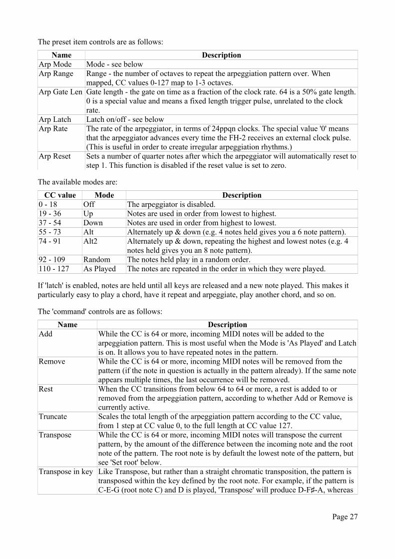
If the FH-2's display is in its default mode when a CC is received that affects an arpeggiator, the display switches to show the state of that arpeggiator:
The top line, from left to right, shows: arpeggiator number; mode; rate; reset interval (if on).
The bottom line shows: range; 'L' if latched; the active command (Transpose, transpose in Key, Set root note, Add, Remove); the current step/highest step; the current note.
If truncate is active, the untruncated highest step is shown above the highest step ('6' in the image above, above '5').
On the right side, below the reset interval, is the current root note.
Portamento
Monophonic MIDI/CV converters use the portamento setting. This sets a glide time between notes played legato ("fingered portamento").
Transpose
Each MIDI/CV converter has a transpose setting, which transposes its notes up or down in semitones.
Euclidean Patterns
These generate rhythmic patterns of output pulses known as Euclidean patterns. For a detailed description of these patterns and how they are commonly found in music around the world see e.g. here10 or here11.
A pattern is described by the total number of steps and the number of pulses (i.e. the number steps on which a pulse is output). There is also the 'rotation' of the pattern. At zero rotation, the first step in the pattern will always be a pulse, and the remaining pulses distributed according to the algorithm. The rotation setting moves the first pulse by a number of steps i.e. moves the down beat.
Each Euclidean generator also has an Accent Rate. If enabled, this superimposes a regular accent on the pattern (so for example you could have a pattern in 16th notes with an accent on every quarter note). In terms of the output, the unaccented pulses are scaled down by a percentage set in the configuration globals (see above).
10 https://en.wikipedia.org/wiki/Euclidean_rhythm11 http://www.hisschemoller.com/blog/2011/euclidean-rhythms/
Page 28
The controls are as follows:Name Description
Pulses See above. A value of '0' effectively turns the generator off.Steps See above. The maximum number of steps is 32.Rotation See above.Rate The rate of the pattern, in terms of 24ppqn clocks. The special value '0' means that
the pattern advances every time the FH-2 receives an external clock pulse. (This is useful in order to create irregular rhythms.)
Gate Length Gate length - the gate on time as a fraction of the clock rate. 64 is a 50% gate length. 0 is a special value and means a fixed length trigger pulse, unrelated to the clock rate.
Accent Rate The accent rate, in terms of 24ppqn clocks, or zero for off (no accents).
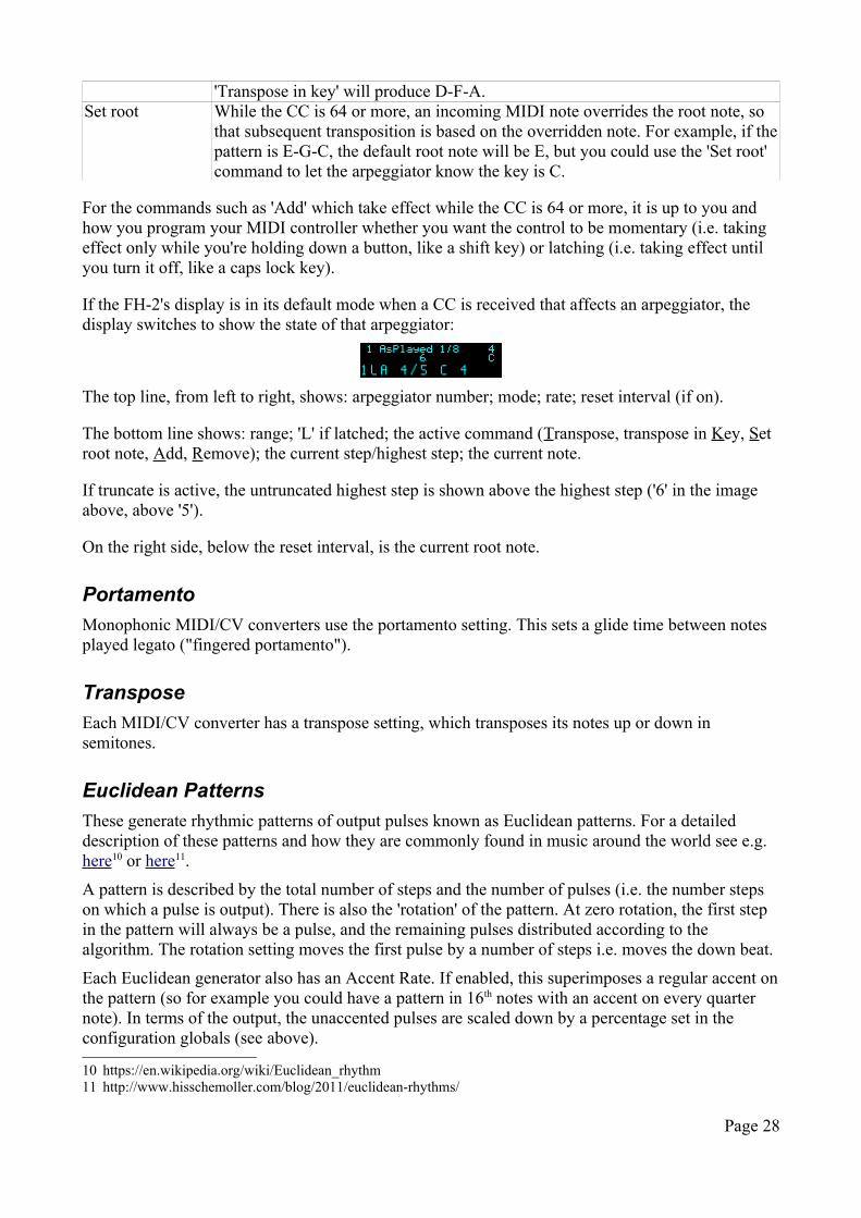
If the FH-2's display is in its default mode when a CC is received that affects a Euclidean pattern generator, the display switches to show the state of that generator:
The display shows the Euclidean pattern number, the pulses/steps, the rotation, the current step, and the rate. Across the top is a graphical representation of the pattern and the current step.
Envelopes
Each MIDI/CV converter of the FH-2 has a per-voice envelope generator, of the traditional ADSR variety. The controls are as follows:
Name DescriptionAttack The envelope's attack time.Decay The envelope's decay time.Sustain The envelope's sustain level.Release The envelope's release time.Range Defines the time range for the Attack, Decay, and Release controls. The options
are 200ms, 500ms, 1s, 2s, 5s, and 10s.Depth The envelope's depth i.e. amplitude. A value of 64 means zero depth; values
greater than 64 mean a positive depth; values below 64 mean a negative depth.
Note that the envelope's depth setting is bipolar. For negative-going envelopes, you will probably want to set the direct output level to give the envelope a non-zero starting point.
Scala
The FH-2's MIDI/CV converters can use microtonal scales defined by the Scala file formats12.
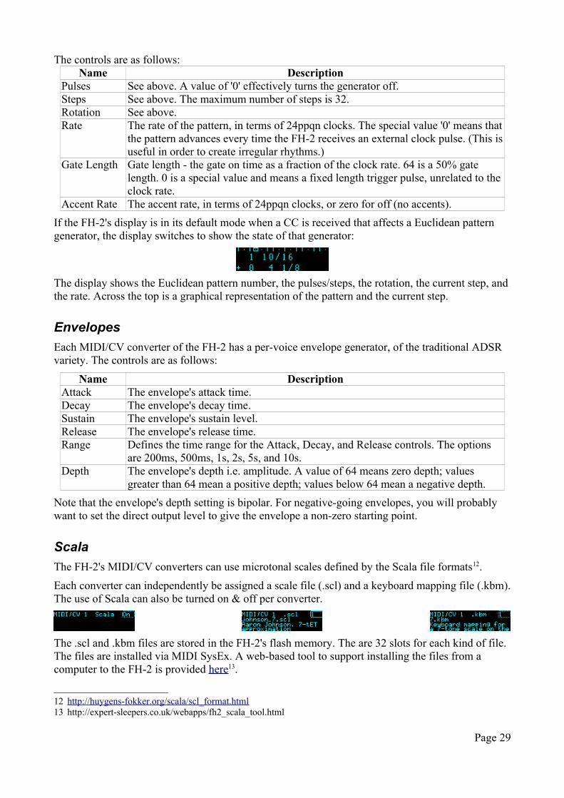
Each converter can independently be assigned a scale file (.scl) and a keyboard mapping file (.kbm). The use of Scala can also be turned on & off per converter.
The .scl and .kbm files are stored in the FH-2's flash memory. The are 32 slots for each kind of file. The files are installed via MIDI SysEx. A web-based tool to support installing the files from a computer to the FH-2 is provided here13.
12 http://huygens-fokker.org/scala/scl_format.html13 http://expert-sleepers.co.uk/webapps/fh2_scala_tool.html
Page 29
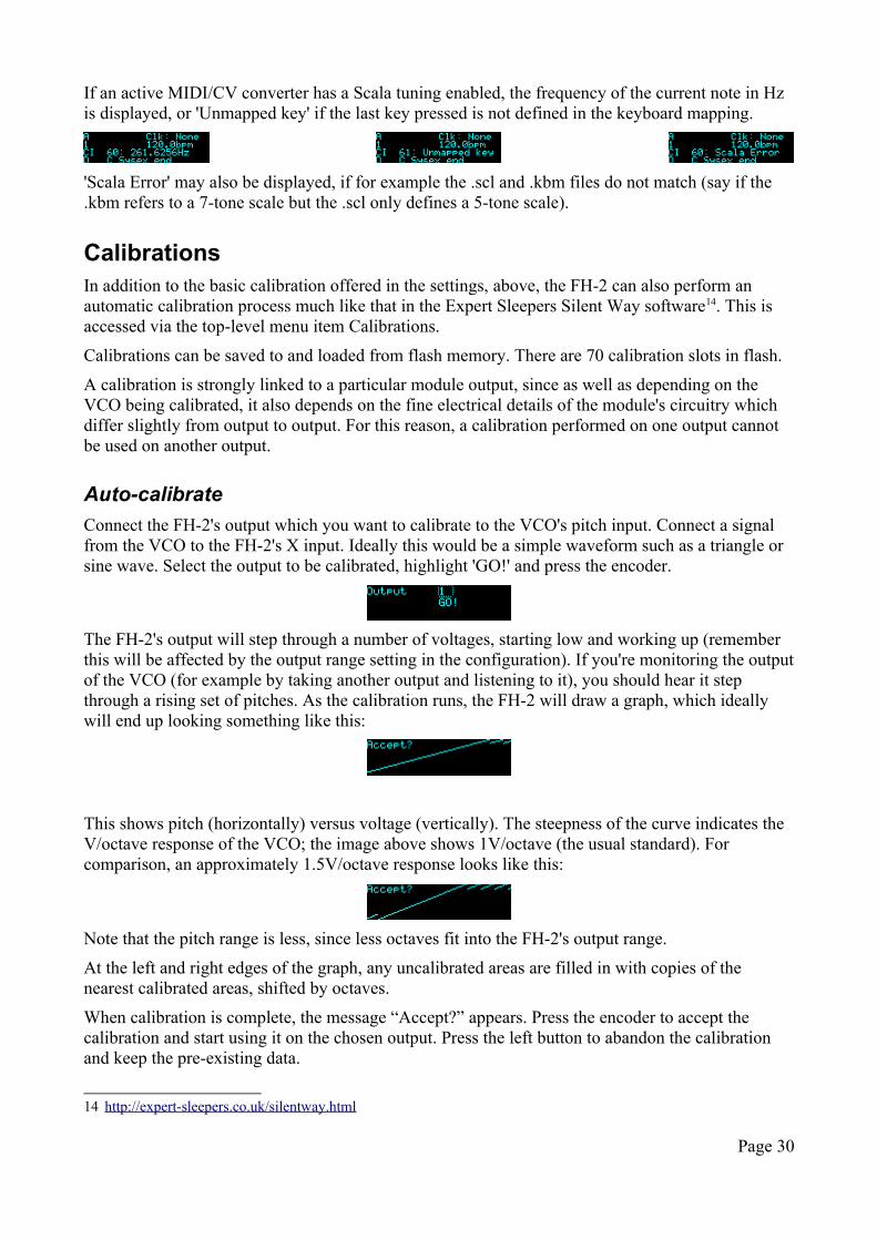
If an active MIDI/CV converter has a Scala tuning enabled, the frequency of the current note in Hz is displayed, or 'Unmapped key' if the last key pressed is not defined in the keyboard mapping.
'Scala Error' may also be displayed, if for example the .scl and .kbm files do not match (say if the .kbm refers to a 7-tone scale but the .scl only defines a 5-tone scale).
CalibrationsIn addition to the basic calibration offered in the settings, above, the FH-2 can also perform an automatic calibration process much like that in the Expert Sleepers Silent Way software14. This is accessed via the top-level menu item Calibrations.
Calibrations can be saved to and loaded from flash memory. There are 70 calibration slots in flash.
A calibration is strongly linked to a particular module output, since as well as depending on the VCO being calibrated, it also depends on the fine electrical details of the module's circuitry which differ slightly from output to output. For this reason, a calibration performed on one output cannot be used on another output.
Auto-calibrate
Connect the FH-2's output which you want to calibrate to the VCO's pitch input. Connect a signal from the VCO to the FH-2's X input. Ideally this would be a simple waveform such as a triangle or sine wave. Select the output to be calibrated, highlight 'GO!' and press the encoder.
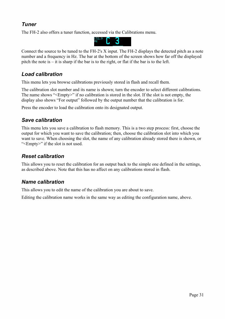
The FH-2's output will step through a number of voltages, starting low and working up (remember this will be affected by the output range setting in the configuration). If you're monitoring the output of the VCO (for example by taking another output and listening to it), you should hear it step through a rising set of pitches. As the calibration runs, the FH-2 will draw a graph, which ideally will end up looking something like this:
This shows pitch (horizontally) versus voltage (vertically). The steepness of the curve indicates the V/octave response of the VCO; the image above shows 1V/octave (the usual standard). For comparison, an approximately 1.5V/octave response looks like this:
Note that the pitch range is less, since less octaves fit into the FH-2's output range.
At the left and right edges of the graph, any uncalibrated areas are filled in with copies of the nearest calibrated areas, shifted by octaves.
When calibration is complete, the message “Accept?” appears. Press the encoder to accept the calibration and start using it on the chosen output. Press the left button to abandon the calibration and keep the pre-existing data.
14 http://expert-sleepers.co.uk/silentway.html
Page 30
Tuner
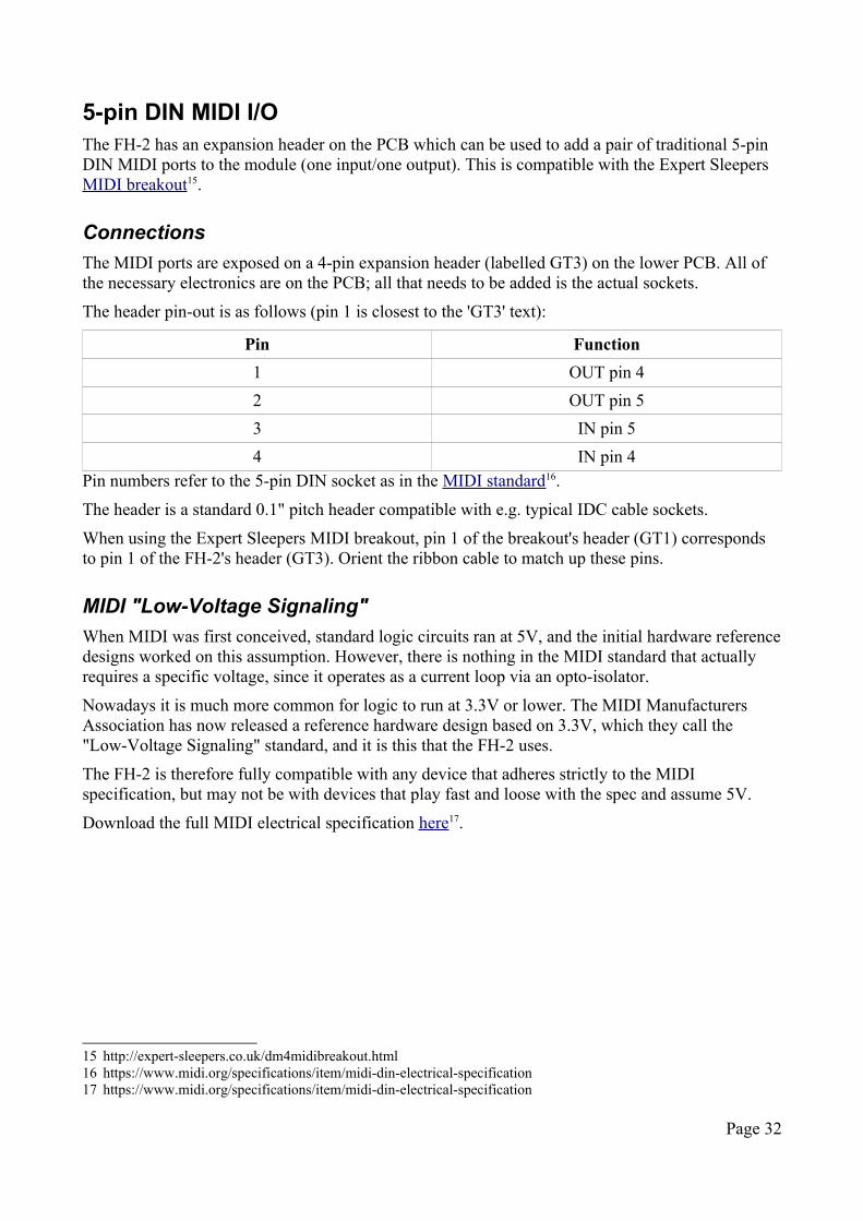
The FH-2 also offers a tuner function, accessed via the Calibrations menu.
Connect the source to be tuned to the FH-2's X input. The FH-2 displays the detected pitch as a note number and a frequency in Hz. The bar at the bottom of the screen shows how far off the displayed pitch the note is – it is sharp if the bar is to the right, or flat if the bar is to the left.
Load calibration
This menu lets you browse calibrations previously stored in flash and recall them.
The calibration slot number and its name is shown; turn the encoder to select different calibrations. The name shows “<Empty>” if no calibration is stored in the slot. If the slot is not empty, the display also shows “For output” followed by the output number that the calibration is for.
Press the encoder to load the calibration onto its designated output.
Save calibration
This menu lets you save a calibration to flash memory. This is a two step process: first, choose the output for which you want to save the calibration; then, choose the calibration slot into which you want to save. When choosing the slot, the name of any calibration already stored there is shown, or “<Empty>” if the slot is not used.
Reset calibration
This allows you to reset the calibration for an output back to the simple one defined in the settings, as described above. Note that this has no affect on any calibrations stored in flash.
Name calibration
This allows you to edit the name of the calibration you are about to save.
Editing the calibration name works in the same way as editing the configuration name, above.
Page 31
5-pin DIN MIDI I/OThe FH-2 has an expansion header on the PCB which can be used to add a pair of traditional 5-pin DIN MIDI ports to the module (one input/one output). This is compatible with the Expert Sleepers MIDI breakout15.
Connections
The MIDI ports are exposed on a 4-pin expansion header (labelled GT3) on the lower PCB. All of the necessary electronics are on the PCB; all that needs to be added is the actual sockets.
The header pin-out is as follows (pin 1 is closest to the 'GT3' text):
Pin Function
1 OUT pin 4
2 OUT pin 5
3 IN pin 5
4 IN pin 4Pin numbers refer to the 5-pin DIN socket as in the MIDI standard16.
The header is a standard 0.1" pitch header compatible with e.g. typical IDC cable sockets.
When using the Expert Sleepers MIDI breakout, pin 1 of the breakout's header (GT1) corresponds to pin 1 of the FH-2's header (GT3). Orient the ribbon cable to match up these pins.
MIDI "Low-Voltage Signaling"
When MIDI was first conceived, standard logic circuits ran at 5V, and the initial hardware reference designs worked on this assumption. However, there is nothing in the MIDI standard that actually requires a specific voltage, since it operates as a current loop via an opto-isolator.
Nowadays it is much more common for logic to run at 3.3V or lower. The MIDI Manufacturers Association has now released a reference hardware design based on 3.3V, which they call the "Low-Voltage Signaling" standard, and it is this that the FH-2 uses.
The FH-2 is therefore fully compatible with any device that adheres strictly to the MIDI specification, but may not be with devices that play fast and loose with the spec and assume 5V.
Download the full MIDI electrical specification here17.
15 http://expert-sleepers.co.uk/dm4midibreakout.html16 https://www.midi.org/specifications/item/midi-din-electrical-specification17 https://www.midi.org/specifications/item/midi-din-electrical-specification
Page 32
MIDI System Exclusive (SysEx)The FH-2 supports a variety of features via MIDI System Exclusive messages. These mainly relate to configuration functions, rather than real-time operation.
SysEx Header
All SysEx messages are prefixed with a manufacturer's ID, which is a unique series of hex bytes assigned by the MIDI Manufacturers Association. The Expert Sleepers ID is 00H 21H 27H, so all SysEx messages relating to Expert Sleepers hardware will begin
F0 00 21 27
Messages for the FH-2 follow this with 2FH:
F0 00 21 27 2F
and then with a byte to identify the specific type of message e.g.
F0 00 21 27 2F 10
Received SysEx messages
01H – Take screenshotF0 00 21 27 2F 01 F7
This causes the FH-2 to respond with a SysEx message containing a capture of its screen.
Note that there is a web-based tool to capture FH-2 screenshots here18.
02H – Display messageF0 00 21 27 2F 02 <NULL terminated ASCII string> F7
Displays the enclosed string on the FH-2's screen.
03H – Set FHX-8GT outputsF0 00 21 27 2F 03 <exp> <n0> <n1> <n2> <n3> F7
Sets the outputs of the FHX-8GT at index <exp>. <n0>-<n3> are four nybbles which each set four outputs of the FHX-8GT and its attached ESX-8GT.
10H – Install configurationF0 00 21 27 2F 10 00 00 <configuration data> F7
Installs the enclosed data as the FH-2's currently active configuration.
11H – Install .sclF0 00 21 27 2F 11 <slot number> <.scl file text> F7
Installs the enclosed data to a Scala scale file slot.
18 http://expert-sleepers.co.uk/webapps/fh2_screenshot_tool.html
Page 33
12H – Install .kbmF0 00 21 27 2F 12 <slot number> <.kbm file text> F7
Installs the enclosed data to a Scala keyboard mapping slot.
21H – Request configuration dumpF0 00 21 27 2F 21 F7
This causes the FH-2 to respond with a SysEx message containing the currently active configuration. The response message is in exactly the format of the '10H - Install configuration' message above, so that it can be recorded into and played back from a SysEx librarian tool (for example, this19).
22H – Request version stringF0 00 21 27 2F 22 F7
This causes the FH-2 to respond with a SysEx message containing the module's version string as text, using the '32H – Message' format, below.
Sent SysEx messages
10H – Install script
See above. This message is transmitted in response to a '21H - Request configuration dump' message, or when the 'Dump configuration via SysEx' menu item is used.
32H – MessageF0 00 21 27 2F 32 <NULL terminated ASCII string> F7
This message is transmitted in response to a '22H - Request version string' message.
33H – ScreenshotF0 00 21 27 2F 33 00 00 <screenshot data> F7
This message is transmitted in response to a '01H – Take screenshot' message.
19 https://www.snoize.com/SysExLibrarian/
Page 34
Command Shell
When a HID keyboard is connected to the FH-2, it is possible to open a command shell and type commands in the programming language Lua20.
The shell is opened and closed by pressing the Escape key. Type a line of Lua and press Return to execute it.
Current limitations include:
• Each command is executed in a completely fresh instance of Lua. There is no persistent state, or storage of function definitions etc.
• There is very little interaction with the FH-2 hardware.
• There is no provision for running code in the background, or in response to MIDI or CV events etc.
All of these things are possible; they may be implemented if anyone thinks it's worthwhile.
Built-in functions
The following functions are defined as extensions to the base Lua language.
firmware()
Inputs: none
Returns: none
Prints the version of the installed firmware.
dac( output, value )
Inputs: output number (1-64), DAC code (0-16383)
Returns: none
Sets the FH-2 or expander output DAC directly to the given value.
20 https://www.lua.org
Page 35
This feature should be considered a prototype. It is by no means complete or fully functional. It is included at this point to gauge interest and invite feedback.
Firmware UpdatesThe FH-2's firmware can be updated using a USB flash drive, which must be formatted as 'FAT' (variously referred to as 'MS-DOS FAT', 'FAT16', 'FAT32'). The process is as follows:
• Download the firmware from the Expert Sleepers website.
• Unzip the download.
• Copy the file 'image.hex' from the unzipped download to the root folder of the USB flash drive.
• Insert the drive into the FH-2's USB A socket.
◦ You are advised to observe basic ESD (electrostatic discharge) precautions - see for example here21. Don't be wearing a nylon sweater in an air conditioned room.
• Restart the FH-2 with the encoder knob pressed. (You can do this by power cycling it, or by rebooting from the Misc menu.) It will go through the first stage of its startup sequence, showing the bootloader version number.
• Keep the knob pressed until the message "Press left button to begin flashing..." is shown.
◦ If at this point the FH-2 shows the message "Could not find the file 'image.hex' on the drive", no firmware file could be found on the drive. Remove the drive and check its contents and formatting.
◦ If the FH-2 stalls on the message “Attempting to mount drive...” the drive is not formatted correctly.
• Press the left button to begin the flashing process. (If you change your mind and don't want to proceed, simply turn the power off.)
• When the flashing process starts, the display updates to indicate progress. Do not remove the drive or turn off the power during the update.
• When the flashing process is complete, the FH-2 will show the message "Success" if successful, or "Error:" plus an error code if there was a problem.
• Press the left button to reboot the FH-2 and resume normal operation.
21 http://www.computerhope.com/esd.htm
Page 36
Acknowledgments'FH-2' logo and boot-up animation by Jason Evans.
The FH-2 uses Lua22, the copyright notice of which is reproduced below.
22 https://www.lua.org/
Page 37
Copyright © 1994–2018 Lua.org, PUC-Rio.
Permission is hereby granted, free of charge, to any person obtaining a copy of this software and associated documentation files (the "Software"), to deal in the Software without restriction, including without limitation the rights to use, copy, modify, merge, publish, distribute, sublicense, and/or sell copies of the Software, and to permit persons to whom the Software is furnished to do so, subject to the following conditions:
The above copyright notice and this permission notice shall be included in all copies or substantial portions of the Software.
THE SOFTWARE IS PROVIDED "AS IS", WITHOUT WARRANTY OF ANY KIND, EXPRESS OR IMPLIED, INCLUDING BUT NOT LIMITED TO THE WARRANTIES OF MERCHANTABILITY, FITNESS FOR A PARTICULAR PURPOSE AND NONINFRINGEMENT. IN NO EVENT SHALL THE AUTHORS OR COPYRIGHT HOLDERS BE LIABLE FOR ANY CLAIM, DAMAGES OR OTHER LIABILITY, WHETHER IN AN ACTION OF CONTRACT, TORT OR OTHERWISE, ARISING FROM, OUT OF OR IN CONNECTION WITH THE SOFTWARE OR THE USE OR OTHER DEALINGS IN THE SOFTWARE.


![Outback Sleepers Product Brochure Final[2] · Outback Sleepers offer the highest quality concrete retaining wall sleepers and precast panels, engineered to achieve wall heights in](https://img.pdfslide.us/doc/110x75/5e8fc5dc543b38593c3f803b/outback-sleepers-product-brochure-final2-outback-sleepers-offer-the-highest-quality.jpg)