Embed Size (px)
DESCRIPTION
Fire and Gas System Overview
Citation preview

1
Presented toPresented to
Our Valued ClientOur Valued Client

Copyright AE Solutions 20062
AgendaAgenda
Introduction AE Solutions Key PersonnelIntroduction AE Solutions Key Personnel Traditional Independent Fire and Gas Solutions Traditional Independent Fire and Gas Solutions AE Solutions SI-FGS HistoryAE Solutions SI-FGS History Definition of a Safety Instrumented Fire & Gas System Definition of a Safety Instrumented Fire & Gas System
(SI-FGS)(SI-FGS) Integrated SI-FGS Features Integrated SI-FGS Features
FGS 1400 SystemFGS 1400 System COTS TechnologyCOTS Technology Cost Effective / ScaleableCost Effective / Scaleable Facility-Wide NetworkingFacility-Wide Networking FM ApprovedFM Approved
FGS Detection InsightsFGS Detection Insights MicroPack CCTV Video MicroPack CCTV Video

Copyright AE Solutions 20063
Brian MerrimanBrian Merriman
President & Operations Manager of AE SolutionsPresident & Operations Manager of AE Solutions BS degrees in Mechanical and Agricultural BS degrees in Mechanical and Agricultural
EngineeringEngineering Registered Professional Engineer Registered Professional Engineer Held technical, sales, marketing and executive Held technical, sales, marketing and executive
positions with Engineering Companies and System positions with Engineering Companies and System IntegratorIntegrator
Member of ISA and NFPAMember of ISA and NFPA Presenter at technical conferences and user seminars Presenter at technical conferences and user seminars
on Safety Lifecycle Executionon Safety Lifecycle Execution

Copyright AE Solutions 20064
Mike Scott PE, CFSEMike Scott PE, CFSE
VP, Process Safety with AE SolutionsVP, Process Safety with AE Solutions BS and Masters Degrees in Mechanical EngineeringBS and Masters Degrees in Mechanical Engineering Registered Professional Engineer in SC,GA,IL & AK Registered Professional Engineer in SC,GA,IL & AK Certified Functional Safety Expert (CFSE)Certified Functional Safety Expert (CFSE) Member CFSE Governance BoardMember CFSE Governance Board Author of numerous technical papers related to process safetyAuthor of numerous technical papers related to process safety Member of ISA and AIChEMember of ISA and AIChE ISA Course Developer / InstructorISA Course Developer / Instructor
SI-BMS WebinarSI-BMS Webinar SI-FGS WebinarSI-FGS Webinar SI-BMS ClassSI-BMS Class
ISA SP84 Committee MemberISA SP84 Committee Member BMS Subcommittee co-chairBMS Subcommittee co-chair FGS Subcommittee co-chairFGS Subcommittee co-chair
ISA Safety Division BMS Subcommittee chairISA Safety Division BMS Subcommittee chair

Copyright AE Solutions 20065
Ken O’Malley PE, CFSEKen O’Malley PE, CFSE
VP Operations of AE SolutionsVP Operations of AE Solutions BS degree in Electrical EngineeringBS degree in Electrical Engineering Registered Professional Engineer Registered Professional Engineer Certified Functional Safety Expert (CFSE)Certified Functional Safety Expert (CFSE) Held technical and executive positions with Held technical and executive positions with
Engineering Companies and System IntegratorEngineering Companies and System Integrator Member of ISA and NFPAMember of ISA and NFPA Project Manager & Engineer for Process Safety Project Manager & Engineer for Process Safety
ProjectsProjects Developer of FGS 1100 & Project Sponsor for SI-FGS Developer of FGS 1100 & Project Sponsor for SI-FGS
Technology Conversion to FGS 1400.Technology Conversion to FGS 1400.

Copyright AE Solutions 20066
Warren JohnsonWarren Johnson
Principal Control System SpecialistPrincipal Control System Specialist FGS Project ManagerFGS Project Manager BS Electrical EngineeringBS Electrical Engineering Registered Professional Engineer Registered Professional Engineer

7
ConventionalConventional Fire Panel Plus Fire Panel Plus Separate SIS, Gas Detection, HVAC Separate SIS, Gas Detection, HVAC
Control, etc.Control, etc.
High Cost of Ownership !!!High Cost of Ownership !!!

The Conventional WayThe Conventional Way
Fire Gas &/or SIS
HMI
Fire I/O Gas I/O
EWS
EWS
HMI
HVAC &/or BPCS Control
HVAC I/O
DCS
Platform A Platform B &/or C Platform D &/or E
NOT

Copyright AE Solutions 20069
FGS with Traditional Fire Panel & Gas PLCFGS with Traditional Fire Panel & Gas PLC
Base Fire System Cost for 50 I/O & SuppressionBase Fire System Cost for 50 I/O & Suppression Separate dedicated PLC system for Gas Monitoring for 30 I/OSeparate dedicated PLC system for Gas Monitoring for 30 I/O Dedicated HVAC Control Panel by VendorDedicated HVAC Control Panel by Vendor Retransmit Cost I/O 100 Points or Multiple Communication Links to Retransmit Cost I/O 100 Points or Multiple Communication Links to
DCS for Logging, Display and TrendingDCS for Logging, Display and Trending I/O Interface Between Multiple Systems to Coordinate Control of I/O Interface Between Multiple Systems to Coordinate Control of
Valves, HVAC Units, Exhaust Fans, Suppression Devices…Valves, HVAC Units, Exhaust Fans, Suppression Devices… Multiple Engineering Workstations, Software Licenses, TrainingMultiple Engineering Workstations, Software Licenses, Training Multiple Operator Platforms w/ TrainingMultiple Operator Platforms w/ Training Multiple Maintenance Platforms w/ Training, Spares, ProceduresMultiple Maintenance Platforms w/ Training, Spares, Procedures Multiple Vendor Interfaces and Coordination Multiple Vendor Interfaces and Coordination Complex System IntegrationComplex System Integration
Required Elements
FGS1400 includes all functionality in single FM approved system

10
Safety InstrumentedSafety InstrumentedFire & Gas SystemsFire & Gas Systems
fromfrom AE SolutionsAE Solutions

Copyright AE Solutions 200611
Safety Instrumented Fire & Gas Safety Instrumented Fire & Gas Systems Systems fromfrom AE Solutions (SI-FGS) AE Solutions (SI-FGS)
Definition of a Safety Instrumented Fire & Definition of a Safety Instrumented Fire & Gas System (SI-FGS)Gas System (SI-FGS)
AE Solutions SI-FGS HistoryAE Solutions SI-FGS History Integrated SI-FGS Features Integrated SI-FGS Features
FGS 1400 SystemFGS 1400 System COTS TechnologyCOTS Technology Cost Effective / ScaleableCost Effective / Scaleable Facility-Wide NetworkingFacility-Wide Networking FM ApprovedFM Approved

Copyright AE Solutions 200612
System comprised of initiating device sensors, logic solvers, final control elements, fire safety functions and / or notification appliances for the purpose of mitigating an event when predetermined conditions are violated.
Safety-Instrumented Fire & Gas System Safety-Instrumented Fire & Gas System (SI-FGS)(SI-FGS)

Safety-Instrumented Fire & Gas System (SI-FGS)Safety-Instrumented Fire & Gas System (SI-FGS)
Proprietary Supervisory Station
PCS7 / Safety MatrixEngr Console

Copyright AE Solutions 200614
NFPA 72 ConsiderationsNFPA 72 Considerations Prescriptive in naturePrescriptive in nature
Provides the minimum set of requirementsProvides the minimum set of requirements Mandates Mandates
Use of listed devicesUse of listed devices Specific architectureSpecific architecture Primary & Secondary power supplies Primary & Secondary power supplies Installation, test and maintenance proceduresInstallation, test and maintenance procedures Statement of compliance from an authorized bodyStatement of compliance from an authorized body Integrity checking of: Integrity checking of:
Initiating DevicesInitiating Devices Notification DevicesNotification Devices Control DevicesControl Devices System WiringSystem Wiring
Copyright AE Solutions 200615
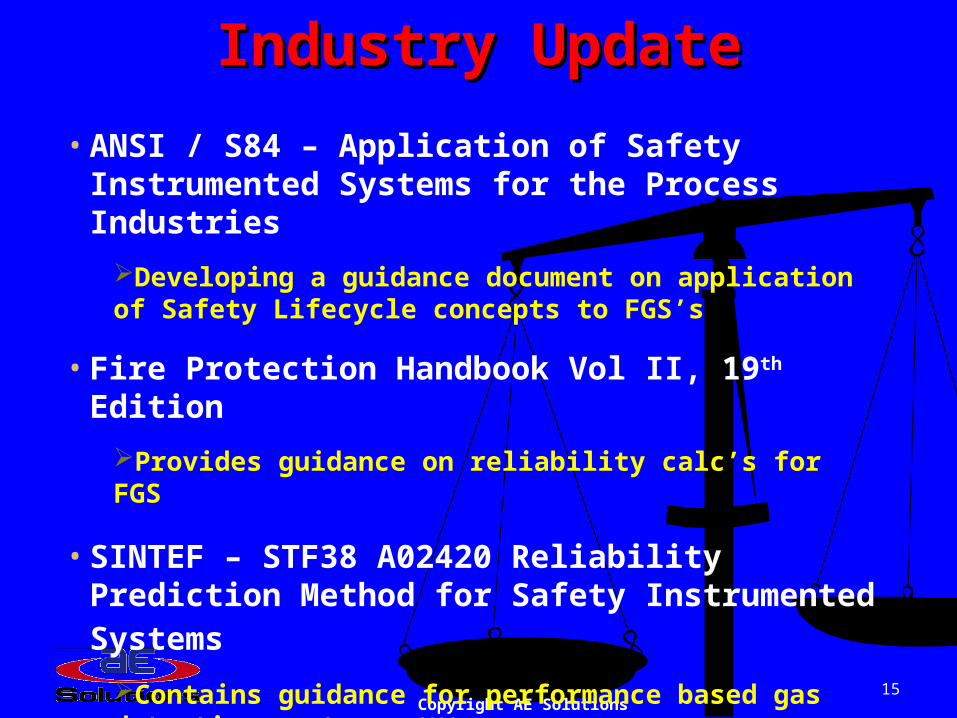
• ANSI / S84 – Application of Safety Instrumented Systems for the Process Industries
Developing a guidance document on application of Safety Lifecycle concepts to FGS’s
• Fire Protection Handbook Vol II, 19th Edition
Provides guidance on reliability calc’s for FGS
• SINTEF – STF38 A02420 Reliability Prediction Method for Safety Instrumented Systems
Contains guidance for performance based gas detection system
Industry UpdateIndustry Update

Copyright AE Solutions 200616
FGS Capable of SIL 3 Safety FGS Capable of SIL 3 Safety Instrumented Function (SIF) Instrumented Function (SIF) ImplementationImplementation
Can Integrate: Can Integrate: Safety Instrumented FunctionsSafety Instrumented Functions
HVAC ControlHVAC Control Exhaust Fan ControlExhaust Fan Control
Combination System - Combination System - SIF Included in FGSSIF Included in FGS

Copyright AE Solutions 200617
Safety-Instrumented Safety-Instrumented Fire & Gas SystemFire & Gas System

Copyright AE Solutions 200618
CP Requirements for FGS1100CP Requirements for FGS1100 Common Safety PLC for Fire, Gas, HVAC & Common Safety PLC for Fire, Gas, HVAC &
Miscellaneous ControlsMiscellaneous Controls Fire Marshall – 3Fire Marshall – 3rdrd Party Approval to NFPA 72 Party Approval to NFPA 72 Gas Approvals for Gas Approvals for
Combustible Gas Std 6320Combustible Gas Std 6320 Toxic Gas Std 6340Toxic Gas Std 6340 ANSI/ISA 12.13.01ANSI/ISA 12.13.01
Common HMI Common HMI Easy integration with BPCSEasy integration with BPCS Common Components Common Components Processor Redundancy OptionProcessor Redundancy Option Monitored I/O CircuitsMonitored I/O Circuits Energize-To-Trip OutputsEnergize-To-Trip Outputs 24-Hour Battery Backup System24-Hour Battery Backup System Possibility for Extended Test IntervalsPossibility for Extended Test Intervals

Copyright AE Solutions 200619
Additional Requirements for FGS1400Additional Requirements for FGS1400
Based on same Platform as Planned BPCS Based on same Platform as Planned BPCS & SIS Upgrades and Expansion Projects& SIS Upgrades and Expansion Projects
Remote I/O option to minimize installation Remote I/O option to minimize installation costscosts
Ethernet Communications for Enhanced Ethernet Communications for Enhanced Networkability & Extended PremiseNetworkability & Extended Premise
Latest Available Architecture from SiemensLatest Available Architecture from Siemens Commercial Off-The-Shelf Technology Commercial Off-The-Shelf Technology
(COTS) (COTS)

Copyright AE Solutions 200620
SI-FGS HistorySI-FGS History
FGS 1100FGS 1100 Based on Siemens Based on Siemens
Quadlog platformQuadlog platform Fire & Gas IntegrationFire & Gas Integration Designed for CPDesigned for CP Available June, 2004Available June, 2004 FM ApprovedFM Approved Installed at Kuparuk and Installed at Kuparuk and
operational since operational since December, 2004December, 2004
FGS 1400FGS 1400 Based on Siemens Latest Based on Siemens Latest
PLC TechnologyPLC Technology Supports Remote I/OSupports Remote I/O Combination SystemCombination System Extremely ScalableExtremely Scalable Large Scale NetworkingLarge Scale Networking Supervising StationSupervising Station FM Approved FM Approved Available Q1, 2006Available Q1, 2006

Copyright AE Solutions 200621
Safety-Instrumented Safety-Instrumented Fire & Gas SystemFire & Gas System

Typical FGS 1400 Fire & Gas System Typical FGS 1400 Fire & Gas System
Proprietary Supervisory Station
PCS7 / Safety MatrixEngr Console

FGS1400 Protected PremiseFGS1400 Protected Premise
RemoteI/O
FGS 1400 Fire & Gas System
Local First Responder Interface
RemoteI/O
Fire, Gas, SIS or
HVAC I/O
ES
LocalI/O
Fire, Gas, SIS or
HVAC I/O
Fire, Gas, SIS or
HVAC I/O

Copyright AE Solutions 200624
Features of The FGS 1400Features of The FGS 1400 A cost-effective turnkey FGS Solution Based on A cost-effective turnkey FGS Solution Based on
Commercial Off The Shelf Technology (COTS)Commercial Off The Shelf Technology (COTS)
FGS 1400 is comprised of the Fire Alarm Panel, the FGS 1400 is comprised of the Fire Alarm Panel, the Battery Charger Panel and the Battery Set Battery Charger Panel and the Battery Set
FM Approved for Both Fire & Gas Detection and SIS FM Approved for Both Fire & Gas Detection and SIS functions within the Same PLC in Compliance with functions within the Same PLC in Compliance with the the “Interference-Free Combination System”“Interference-Free Combination System” paragraph of NFPA 72paragraph of NFPA 72
Designed to Levels of Reliability and Availability Designed to Levels of Reliability and Availability Commensurate with National Safety Standards for Commensurate with National Safety Standards for Safety Instrumented Systems (SIS)Safety Instrumented Systems (SIS)
Highly Scalable Solution, 50 to 50,000 I/O Highly Scalable Solution, 50 to 50,000 I/O

Copyright AE Solutions 200625
Features of The FGS 1400Features of The FGS 1400 Includes Interface Capability to a Wide Variety of Sensors and Includes Interface Capability to a Wide Variety of Sensors and
Final Control ElementsFinal Control Elements Simple Touch Pad or Optional PCS 7 Based Local First Simple Touch Pad or Optional PCS 7 Based Local First
Responder Interface with Graphics Capable Display Responder Interface with Graphics Capable Display Developed around the Siemens Simatic S7-400F SIL3 Certified Developed around the Siemens Simatic S7-400F SIL3 Certified
Safety PLC Platform Safety PLC Platform Communication to Other Control Systems via Hardwired Communication to Other Control Systems via Hardwired
Industrial Ethernet, Profibus I/O or ModbusIndustrial Ethernet, Profibus I/O or Modbus Powerful Engineering Station / HMIPowerful Engineering Station / HMI
Siemens PCS-7Siemens PCS-7 Siemens Safety Matrix Siemens Safety Matrix
Cause & Effect Interlock Configuration & Display for Fire & Cause & Effect Interlock Configuration & Display for Fire & Gas Detection / Suppression SystemGas Detection / Suppression System

Copyright AE Solutions 200626
FGS 1400 System I/O CircuitsFGS 1400 System I/O Circuits Both analog & discrete Class B, Style A Initiating Both analog & discrete Class B, Style A Initiating
Device Circuits (IDC)Device Circuits (IDC) Up to 20 digital devices per circuitUp to 20 digital devices per circuit
NFPA 72 Class B, Style W Notification Appliance NFPA 72 Class B, Style W Notification Appliance Circuits (NAC)Circuits (NAC) Up to 10 Amps per circuitUp to 10 Amps per circuit
Both energize-to-trip and de-energize-to-trip Fire Safety Both energize-to-trip and de-energize-to-trip Fire Safety Functions (FSF)Functions (FSF)
Suppression Device Circuits (SDC) Suppression Device Circuits (SDC) 2 Amps per circuit2 Amps per circuit
Meets Integrity Monitoring requirements of NFPA 72Meets Integrity Monitoring requirements of NFPA 72

Copyright AE Solutions 200627
Local Touch Panel First Local Touch Panel First Responder InterfaceResponder Interface
Color Graphics LCD on the Fire Panel Color Graphics LCD on the Fire Panel Displays System Status and Diagnostic Displays System Status and Diagnostic
InformationInformation Fire Alarm Zone MonitoringFire Alarm Zone Monitoring Active and Historical Alarm ListsActive and Historical Alarm Lists Siemens Hardened Touch Panel Siemens Hardened Touch Panel
(TP270)(TP270) WinCC Flexible ApplicationWinCC Flexible Application

Copyright AE Solutions 200628
Optional - Local PCS7 First Optional - Local PCS7 First Responder InterfaceResponder Interface
Color Graphics HMI on the Fire Panel Color Graphics HMI on the Fire Panel Displays System Status and Diagnostic Displays System Status and Diagnostic
InformationInformation Fire Alarm Zone MonitoringFire Alarm Zone Monitoring Active and Historical Alarm ListsActive and Historical Alarm Lists Safety Matrix ViewerSafety Matrix Viewer Siemens Hardened Industrial PCSiemens Hardened Industrial PC Integrated PCS7 HMI ApplicationIntegrated PCS7 HMI Application

Copyright AE Solutions 200629
Engineering Station (ES)Engineering Station (ES)
Implemented Using Siemens Safety Implemented Using Siemens Safety Matrix Configuration and Monitoring Matrix Configuration and Monitoring SoftwareSoftware
Located Anywhere on Ethernet Located Anywhere on Ethernet Network Network
Functionality includes:Functionality includes: Automated System Cause & Effect Automated System Cause & Effect
Configuration MethodologyConfiguration Methodology Operational HMI for System MonitoringOperational HMI for System Monitoring Bypassing Capability for Troubleshooting, Bypassing Capability for Troubleshooting,
Maintenance & TestingMaintenance & Testing

Copyright AE Solutions 200630
Battery Back-Up SystemBattery Back-Up System Meets all NFPA 72 Requirements for 24 Hour Battery Meets all NFPA 72 Requirements for 24 Hour Battery
SupplySupply 120 VAC System Input120 VAC System Input Battery ChargerBattery Charger 24 VDC to Fire Circuits with Ground Fault Detection24 VDC to Fire Circuits with Ground Fault Detection DC / DC Converter for Regulated 24 VDC for Other DC / DC Converter for Regulated 24 VDC for Other
ComponentsComponents Individual Alarm Outputs to the Processor for:Individual Alarm Outputs to the Processor for:
AC Power FailureAC Power Failure Battery Charge LevelBattery Charge Level Charger HealthCharger Health

Battery Back-Up SystemBattery Back-Up System
Typical Battery Bank
Battery Charger Panel

The FGS1400 The FGS1400

Systembus Industrial Ethernet / Fast Ethernet
AS 414 FHAS 417 FH
ET 200MFail-Safe
Small Scale Simplex
FGS 1400
AS 414 FHAS 417 FH
PR
OF
IBU
S-D
P
ET 200MFail-Safe
ET 200MFail-Safe
ET 200MFail-Safe
PR
OF
IBU
S-D
P
GL
AS
S F
IBE
R
ET 200MFail-Safe
PR
OF
IBU
S-D
P
First Responder Interface
OLM
Remote I/O Panel
ET 200MFail-Safe
ET 200MFail-Safe
Local I/O, Simplex Controller, PCS7 First
Responder HMI
Local I/O, Redundant Controller, WinCC Flex
First Responder HMI
Local & Remote I/O, Redundant Controller,
PCS7 First Responder HMI
FGS 1400 ScalabilityFGS 1400 Scalability

PCS7 OS Single Station w/ Safety
Matrix Viewer
Proprietary Supervision Station
WinCC Flex Touchpanel FRI,
Redundant Controller
PCS7 OS Single Station w/ Safety Matrix Viewer &
Dual Monitor
Systembus Industrial Ethernet / Fast Ethernet
FGS 1400
AS 414 FHAS 417 FH
FGS 1400
AS 414 FAS 417 F
FGS 1400
AS 414 FHAS 417 FH
Remote or Local Monitoring Station
Remote or Local Engineering Station
(1 Required)
FGS 1400 Simple ArchitecturesFGS 1400 Simple Architectures
WinCC Flex Touchpanel FRI,
Simplex Controller
PCS 7 PC Based FRI, Redundant
Controller
PCS7 ES w/ Safety Matrix Tool

Operator Terminals
(1...16)
Terminalbus Ethernet
EngineeringStation (ES)
OS-Server (1...6)
Systembus Industrial Ethernet / Fast Ethernet
FGS 1400
AS 414 FHAS 417 FH
FGS 1400
AS 414 FHAS 417 FH
FGS 1400
AS 414 FHAS 417 FH
Remote or Local Engineering Station
(1 Required)
Remote or Local Single Stations (As Required)
FGS 1400 HMI ArchitecturesFGS 1400 HMI ArchitecturesClient - Server Architecture

PCS 7 @Warehouse
ERP
EthernetOperator Terminals
(1...16)
Terminalbus Ethernet
OS-Server (1...6)
Systembus Industrial Ethernet / Fast Ethernet
AS 414 FHAS 417 FH
PR
OF
IBU
S-D
P
Y-Link
DP/PA-Link
AS 414 FHAS 417 FH
ET 200MFail-Safe
ET 200MFail-Safe
ET 2a00MFail-Safe
ET 200MFail-Safe
Process Safety (SIS)
ET 200M
Process Control (BPCS)
MES
Completely Integrated ArchitectureCompletely Integrated ArchitectureManned Control Center
ET 200MFail-Safe
AS 414 FHAS 417 FH
PR
OF
IBU
S-D
P
GL
AS
S F
IBE
R
ET 200MFail-Safe
Fire & Gas (FGS1400)
PR
OF
IBU
S-D
P
First Responder Interface
Remote I/O Panel
OS Single -system
EngineeringStation ES
OLM
Copyright AE Solutions 200637

38
Distribution and Effectiveness Distribution and Effectiveness aspects of fire and gas aspects of fire and gas
detector placementdetector placement

Copyright AE Solutions 200639
SI-FGS TermsSI-FGS TermsGeographic Detector CoverageGeographic Detector Coverage
Is defined as the fraction of process area Is defined as the fraction of process area where - if a fire of defined size / volume where - if a fire of defined size / volume occurs – the event is detectable by a given occurs – the event is detectable by a given sensor placement array sensor placement array (and voting logic if (and voting logic if automatic process actions are required)automatic process actions are required)
e.g. - 90% probability that 2ooN fire detectors will be capable e.g. - 90% probability that 2ooN fire detectors will be capable of sensing a given fire of a given intensity (e.g. 10 KW)of sensing a given fire of a given intensity (e.g. 10 KW)

Copyright AE Solutions 200640
SI-FGS TermsSI-FGS TermsScenario Detector CoverageScenario Detector Coverage
Is defined as the fraction of fire hazard Is defined as the fraction of fire hazard scenarios that are detectable by a given scenarios that are detectable by a given sensor placement array sensor placement array (and voting logic if (and voting logic if automatic process actions are required)automatic process actions are required)
e.g. - 90% probability that a fire hazard of given intensity e.g. - 90% probability that a fire hazard of given intensity (e.g. 10 KW) will be detected by 2ooN fire detectors for a (e.g. 10 KW) will be detected by 2ooN fire detectors for a given hazard scenario (e.g. flange fire)given hazard scenario (e.g. flange fire)

Copyright AE Solutions 200641
FGS EffectivenessFGS Effectiveness
The Probability of Failure on Demand The Probability of Failure on Demand (PFD(PFDavgavg ) ) associated with the FGS associated with the FGS Safety Instrumented Function Safety Instrumented Function
This is the traditional PFDThis is the traditional PFDavgavg component calculated for component calculated for
sensors / logic solver / and final elements for a given sensors / logic solver / and final elements for a given architecture and test intervalarchitecture and test interval
SIL target defined for the Fire Safety FunctionsSIL target defined for the Fire Safety Functions
SI-FGS TermsSI-FGS Terms

Copyright AE Solutions 200642
Mitigation EffectivenessMitigation Effectiveness The probability that the actions of the The probability that the actions of the final elements prevent small fire or final elements prevent small fire or accumulation from escalating to a accumulation from escalating to a large fire or accumulation. large fire or accumulation.
Examples of where the mitigation action may Examples of where the mitigation action may not be 100% effective are as follows:not be 100% effective are as follows:
Deluge does not completely put out the fireDeluge does not completely put out the fire Isolation and / or bleed of pressure from the system is Isolation and / or bleed of pressure from the system is
not fast enough to prevent the accumulation due to the not fast enough to prevent the accumulation due to the leak from reaching the large catastrophic cloud size.leak from reaching the large catastrophic cloud size.
Etc.Etc.
SI-FGS TermsSI-FGS Terms

Copyright AE Solutions 200643
SI-FGS ConceptsSI-FGS Concepts
S1* S2* S3 = “effectiveness” of Gas Detector System
FGS Effectiveness
(0.95)
Gas Leak occurs(‘x’/yr)
Detection Coverage
(0.90)
(0.10)
(0.05)
F2
S2
S1
F1
Mitigation Effectiveness
(0.80)
(0.20)
S3
F3
$
$$$
$$$
$$$

Copyright AE Solutions 200644
CCTV Fire CCTV Fire Monitoring Monitoring
SystemsSystems
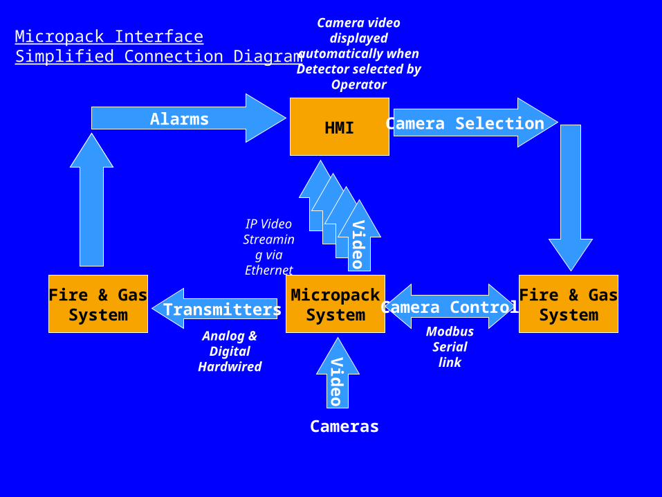
MicropackSystem
Vid
eo
Cameras
Fire & GasSystem Transmitters
Fire & GasSystemCamera Control
Modbus Serial link
Analog & Digital
Hardwired
Vid
eo
IP Video Streamin
g via Ethernet
Alarm
s
Alarms HMI Camera Selection
Camera video displayed
automatically when Detector selected by
Operator
Micropack InterfaceSimplified Connection Diagram

Hub controller
TERMINALS
Video JetTCP/IP
Network
FGS 1400Supervising Station
Micropack Lap topFor commissioning only
This set up allows FGS 1400 to select and display video from the Micropack cameras on the FGS Supervising Station
Video Jet
Video Jet
Video Jet
FGS 1400Controller
4-20mA
1TO 12 DETECTORS
Video Switcher
Design Based on Saturn for CavendishOne Hub Controller Required Per 12 Visual Flame Detectors
RS 485 Modbus

Copyright AE Solutions 200647
The FDS-101The FDS-101An Imaging Based Flame DetectorAn Imaging Based Flame Detector

48
FFire & Gas Detection ire & Gas Detection MappingMapping

Copyright AE Solutions 200649
Typical Fire Detection TargetsTypical Fire Detection Targets
Alarm Control ActionA 10kW 10kWB 10kW 50kWC 100kW 250kWS
GradeFire Size (RHO)
Defined By Hazard
Typical Offshore Platform

Copyright AE Solutions 200650
Study MethodologyStudy Methodology
1. Prepare performance targets
2. Collect applicable drawings of equipment installation
3. Survey the areas of interests w/ digital photographs
4. Assess the performance of existing detection using custom software
5. Identity gaps between ‘actual’ and ‘required’ performance
6. Propose measures to close these gaps

Copyright AE Solutions 200651
Mapping SoftwareMapping Software
• The software that implements guidance is Micropack’s FDA and GDA custom software package.
• The process starts by converting a detector field of view picture into a “2 ½ D software footprint” taking account all obstructions shown in the photograph.
• This footprint is overlaid onto a ‘graded’ equipment layout
• The resulting coverage is assessed using the performance targets.

Grade Maps & AssessmentsGrade Maps & Assessments Notes : (Detection Scenarios)
1. The control and alarm target fires can be 'seen' by the flame detection system
2. Because the Grade B detection target requires an alarm to a smaller fire size it is possible for two detectors to respond to the 50Kw control action target while being unable to respond to a smaller 10Kw alarm fire target.
3. This case occurs when only one detector can 'see' the fire - two detectors are required for control action.
4. This case occurs when the detector is too far from the hazards to 'see' the specified target fire size. If the fire incident escalated then the detector will respond
5. No detector can see this hazard and there will be no response.

Test Ground Grade MapTest Ground Grade Map
The vessels are all grade B
This the Ex test ground with the vessels graded

Detector 1
with No Obstructions
Test Ground – FD1Test Ground – FD1

Detector 2
with No Obstructions
Test Ground – FD2Test Ground – FD2

This is the area’s assessment with no
obstructions interfering with the FD1 field of view.
Notice Very High Level of Coverage
Test Ground – Assess 1Test Ground – Assess 1

Detector 1 With Obstructions
Test Ground – FD1aTest Ground – FD1a

Detector 2 With Obstructions
Test Ground – FD2aTest Ground – FD2a

This is the area’s assessment with obstructions shown
interfering with the detectors’ field of view.
Notice very poor level of coverage
Test Ground – Assess 2Test Ground – Assess 2
Copyright AE Solutions 200660
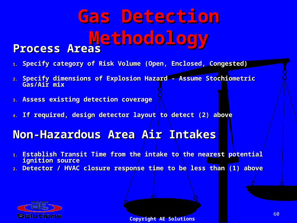
Gas Detection MethodologyGas Detection MethodologyProcess AreasProcess Areas1.1. Specify category of Risk Volume (Open, Enclosed, Congested)Specify category of Risk Volume (Open, Enclosed, Congested)
2.2. Specify dimensions of Explosion Hazard - Assume Stochiometric Gas/Air mixSpecify dimensions of Explosion Hazard - Assume Stochiometric Gas/Air mix
3.3. Assess existing detection coverageAssess existing detection coverage
4.4. If required, design detector layout to detect (2) aboveIf required, design detector layout to detect (2) above
Non-Hazardous Area Air IntakesNon-Hazardous Area Air Intakes
1.1. Establish Transit Time from the intake to the nearest potential ignition sourceEstablish Transit Time from the intake to the nearest potential ignition source2.2. Detector / HVAC closure response time to be less than (1) aboveDetector / HVAC closure response time to be less than (1) above

GDA Grade Map (6m)GDA Grade Map (6m)

GDA Assessment (6m)GDA Assessment (6m)

Copyright AE Solutions 200663
Smoke & Heat DetectionSmoke & Heat Detection Assessed against NFPA 72
Detector spacing Ceiling Height Air change rate
Air Movement Study

Copyright AE Solutions 200664
Comprehensive Survey Report Survey Report
Details of each area reviewed including:Details of each area reviewed including: Area Description/Hazards/Performance Area Description/Hazards/Performance
TargetsTargets Existing DetectionExisting Detection
FDA and GDA Assessments.FDA and GDA Assessments. Summary of all recommendationsSummary of all recommendations
Detector Additions / Deletions / RelocationsDetector Additions / Deletions / RelocationsCAD Layout DrawingsCAD Layout Drawings

Applied Engineering Solutions, Inc.
Thank You! Are There Any…
www.aesolns.com